

Page 1
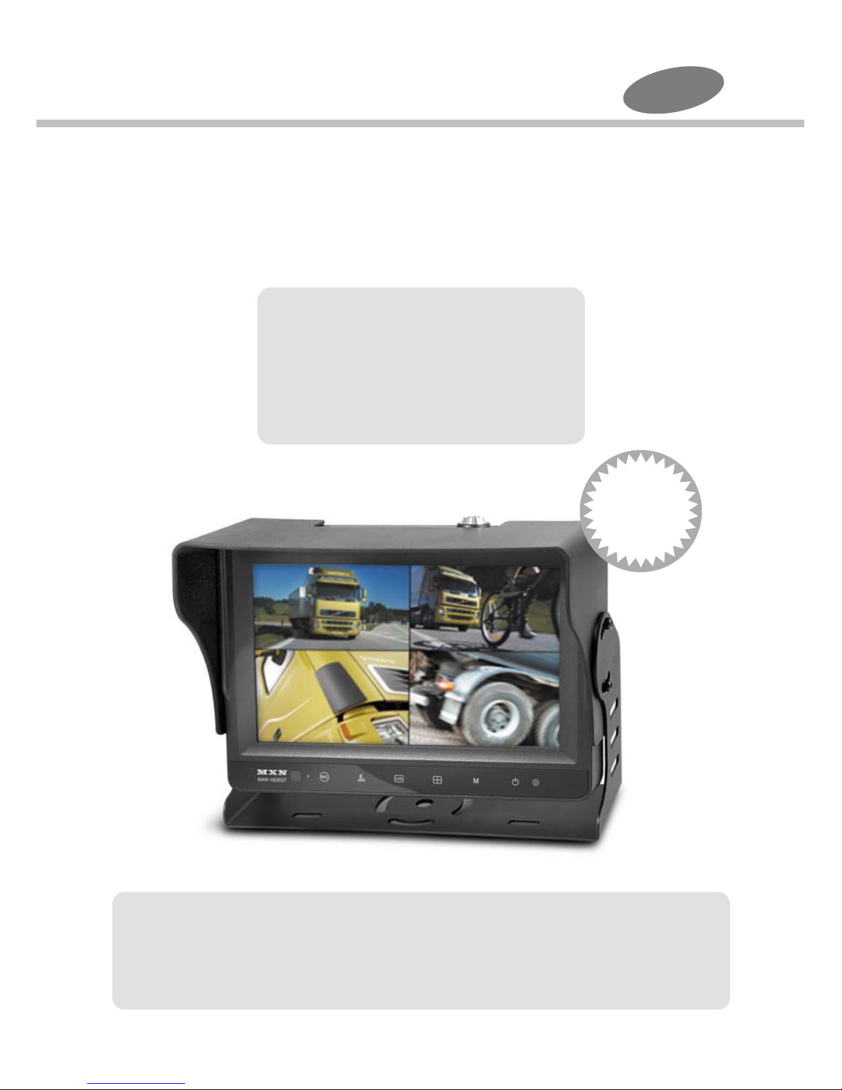
8" Digital Video Recorder for Car
Instruction Manual(Ver. 1.0)
Thank you for purchasing our DVR for car. Please read this manual before
you use the product. The product may be different from the described in
the manual depending on renewal and/or upgrade of S/W version and
performance and it can be altered without notice.
Index
1. Caution
2. Components of the product
3. How to use the product
4. How to install the product
5. How to use PC Player
6. Specification
4ch.
MXN-HD8DVRQ
IP67
Water
Proof
Page 2
Caution
For your safe operation, please read this manual before you start to use the product.
We inform you that our company shall not be responsible for failures and troubles
that are occurred due to misuse or neglection of the cautions written on this manual.
Operating this equipment when driving a car might cause an accident. Use the
equipment after parking or stopping the car in a safe area.
When wiping off the dust, use a soft fabric instead of liquid solvents (thinner,
benzene etc.) solution or a wet rag.
Do not press the liquid crystal screen hard. It might be damaged by hard pressure.
Do not drop or give shock. It might cause breakdown or damage.
Do not dismantle the product arbitrarily. We do not supply free after service for
an arbitrarily dismantled product.
Touching the power with a wet hand causes electric shock. Caution required.
For accessories or cables to connect with the product, it is recommended to
use honest goods from our company. We are not responsible for any problems
caused by fraudulent articles.
Do not disconnect the power cable during using the product. It might cause
damage to the product.
Note: This equipment has been tested and found to comply with the limits for a
Class A digital device, pursuant to part 15 of the FCC Rules. These limits are
designed to provide reasonable protection against harmful interference when
the equipment is operated in a commercial environment. This equipment generates,
uses, and can radiate radio frequency energy and, if not installed and used in
accordance with the instruction manual, may cause harmful interference to radio
communications. Operation of this equipment in a residential area is likely to
cause harmful interference in which case the user will be required to correct the
interference at his own expense.
Modifications not expressly approved by the manufacturer could void the user's
authority to operated the equipment under FCC rules.
FCC (Federal Communications Commission
)
1
Page 3
Caution
SD Card
Do not pull out the SD card during playing or recording process.
Use proper type SD card: it should be higher than Class 10 level SD card.
Recommended brands of SD card: Sandisk, Transcend or Samsung.
Please check the mark as "Class10 & Full-HD" on the package before you
purchase SD card.
Removal Magnet
There is a magnet in the monitor's backside to prevent discharge of the internal
back-up battery.
This magnet needs to be removed before first time use of model MXN-HD8DVRQ.
Unscrew the bolt in the monitor's backside by L-wrench and then remove the magnet
under the bolt.
After removing the magnet, the built-in back-up battery is activated.
Back-up Battery Recharge
The back-up battery can be recharged when the ACC is on (Drive Mode).
(If the ACC if off, it is not recharged for protection of the car battery.)
When it is fully charged, recharging is automatically stopped.
It takes about 5 or more hours to fully charge the battery.(Recharging time may be
different depending on temperature and circumstances.)
It may take longer to charge batteries unused for a long time.
The voltage of the back-up battery can be checked on [Battery Voltage] menu.
(See: Battery Voltage, Page 27.)
Caution : This part informs what to keep in mind or understand and
what caution is required to use the product.
Ref (reference) : Reference is about functional explanation
Amplified explanation is as follows.
2
Page 4
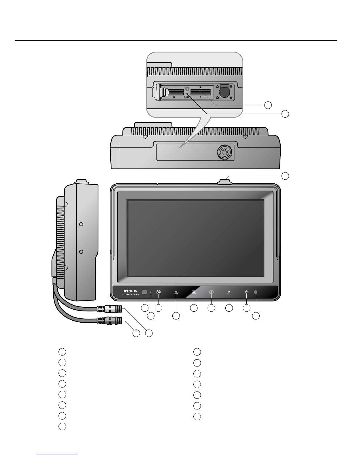
Components of the product
1112
123
4
5 6 7 8
9
10
15
14
1
2
3
4
5
6
7
8
Remo-con Receiving Window
Recording Display LED
Recording START/STOP Button
Event Recording Button
Screen ON/OFF Button
Channel Switch Button
Menu ON/OFF Button
Power ON/OFF Button
9
10
11
12
13
14
15
illuminance Sensor
SD Card Cover and Lock
Power Cable (Blue Cable)
Camera Cable (Black Cable)
Touch Screen
SD Card Slot (4 slots)
Reset Button
3
Page 5
7
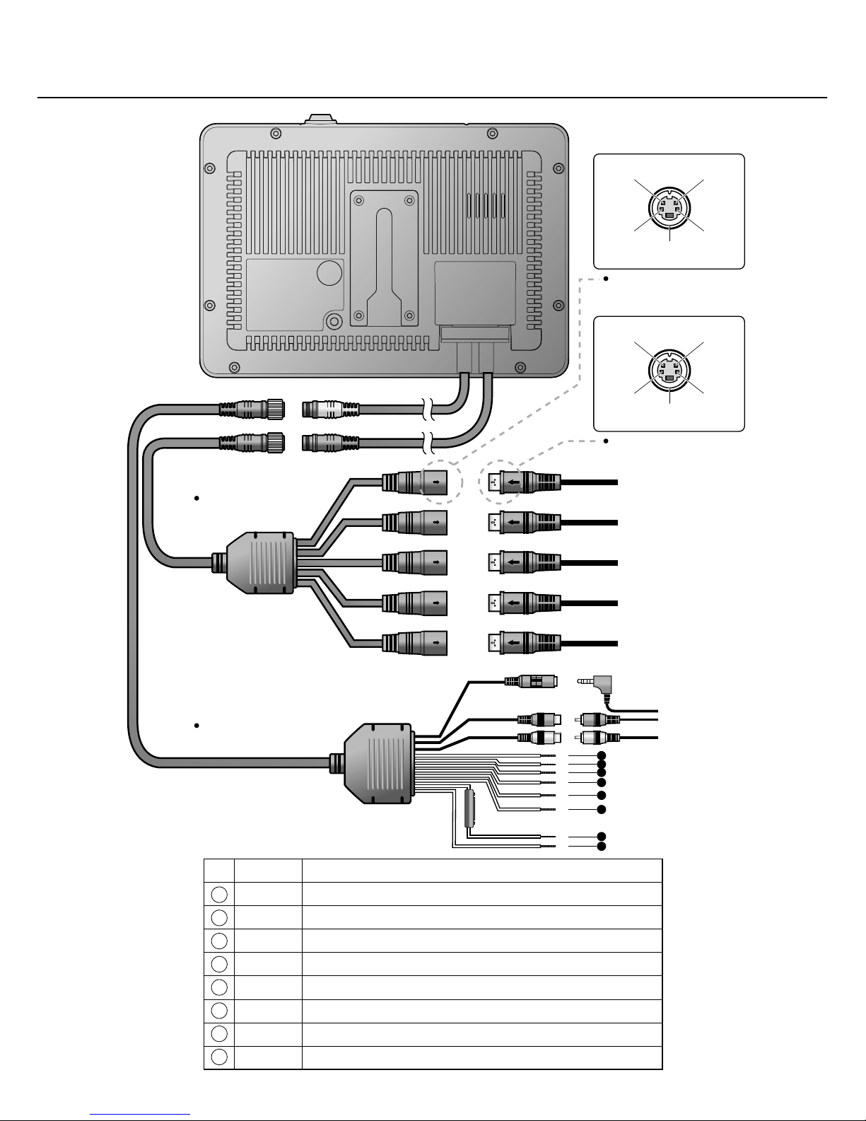
System Connection
1
2
3
4
5
6
7
8
VIDEO IN/OUT
EXT. GPS Module
AUDIO IN/OUT
5
4
3
2
1
6
8
AUDIO in
DC 12VVIDEO in
NC
(Optional : Heater/Shutter)
GROUND
Camera connection
Camera Cable
Blue
Black
Blue
Black
Black
Yellow
Red
Power Cable
Camera 1
Camera 2
Camera 3
Camera 4
Camera 5
NO. Wire Color Label
GRAY Trigger 3 ( 9 ~ 30V DC, via direction light, etc. )
BLUE Trigger 4 ( 9 ~ 30V DC, via direction light, etc. )
GREEN Trigger 2 ( 9 ~ 30V DC, via direction light, etc. )
ORANGE Trigger 1 ( 9 ~ 30V DC, via direction light, etc. )
BROWN ACC Power ( 12 ~ 36V DC, via ignition )
WHITE Speed Pulse (via tachograph, 10 ~ 200 Hz )
RED B+ Power (12 ~ 36V DC, via Battery )
BLACK Ground
AUDIO in
DC 12V VIDEO in
NC
(Optional : Heater/Shutter)
GROUND
Monitor connection
Components of the product
4
Page 6
Components of the product
SD Card Cover & Lock
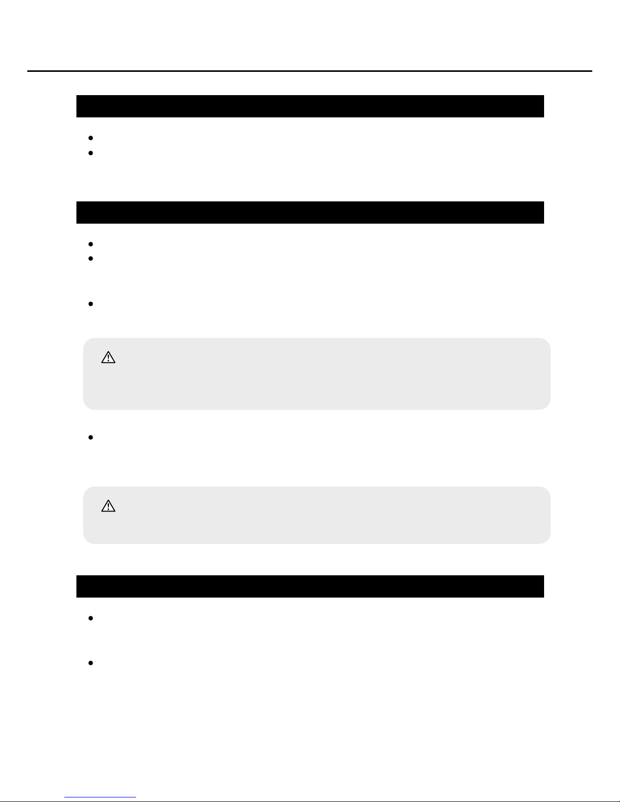
The SD card cover protects SD card on the top of the device.
SD Card Cover is locked up and you can use only the enclosed key to open and
close it.
When removing the card, push the end of it with a finger tip. Then it is unlocked and
comes out. If the card is pushed too hard it might popped out toward your face.
Please push it gently.
How to use SD Card
There are total 4 slots for the SD card.
For each slot, it is possible to equip a SD card (separate purchase) with up to 32 GB
capacity. (total capacity of 128GB)
How to insert/remove card: Pay attention not to confused with the front and the back
sides of the card before inserting it and push the card into the slop entirely.
Reset
When there is an error or malfunction in the operation of the product please
press the reset button.
Reset button is located in the hole between No.1 and No.3 SD cards under
the SD card cover on the top of this product.
Caution:
Please make it sure that the front side of the card is up. When the card is inserted
in a wrong way, there might be break down or the card wouldn't come out.
Caution:
The SD card might not be recognized depending on manufacturer and memory.
5
Page 7
Components of the product
Touch Screen
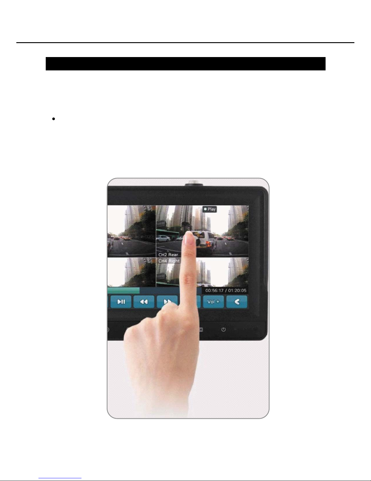
How to use Touch Screen:
It is also possible to control or set functions of the equipment by touching the screen.
For full instructions about the touch screen function, please see [How to use the
product] in the manual.(See: How to use the product, Page 12.)
Touching the small screen of each channel at the multi-screen mode brings a full
screen for the channel.
6
Page 8
Components of the product
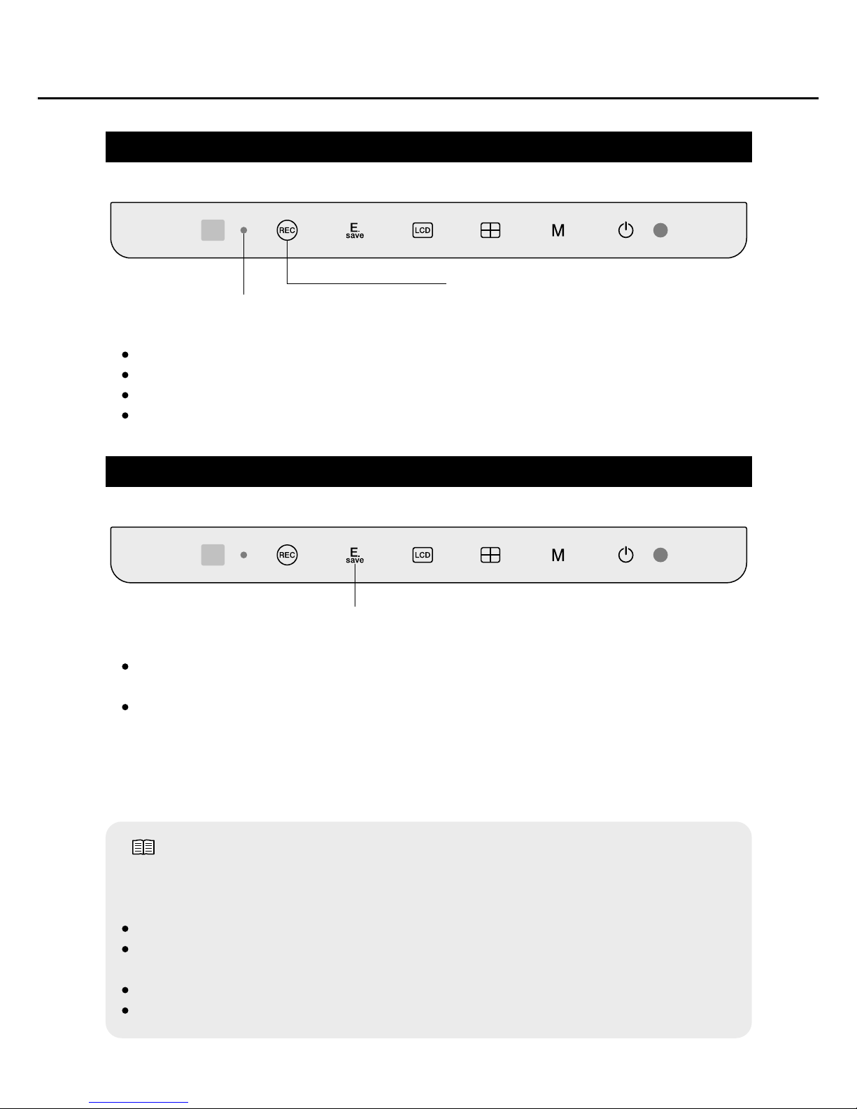
Manual Operation of Record Button(Manual Recording)
Event Recording Button (Emergent Recording)
E.save button can be used for emergency recording at the moment. (Unlike REC
button, it also records former 15 seconds before pressing the button.)
E.save Recording Time
1) Unless normal recording is on, it helps to record total 30 seconds more of
15 seconds each before and after the operation.
2) During normal recording, it is possible to record by using Event Rec. Time Set.
function.(See: Event Rec. Time Set, Page 19.)
Note:
Constant recording (recording by REC button click, by Power On Auto Rec
setting)refers to recording at the drive mode.(See: Power On Auto Rec, Page 18.)
During record, red LED on the left side of REC button is on.
It is not possible to stop it manually and it is automatically stopped when
recording is done.
When recording is finished LED also goes off.
Recorded files are stored in Event folder of Player.
When REC button is clicked, all channels are recorded.
During record, red LED on the left side of REC button is on.
One more click ceases recording and LED will be off.
Recorded files are stored in Normal folder of Player.
Recording Display LED
Recording Start/Stop Button
Event Recording Button
7
Page 9
Components of the product
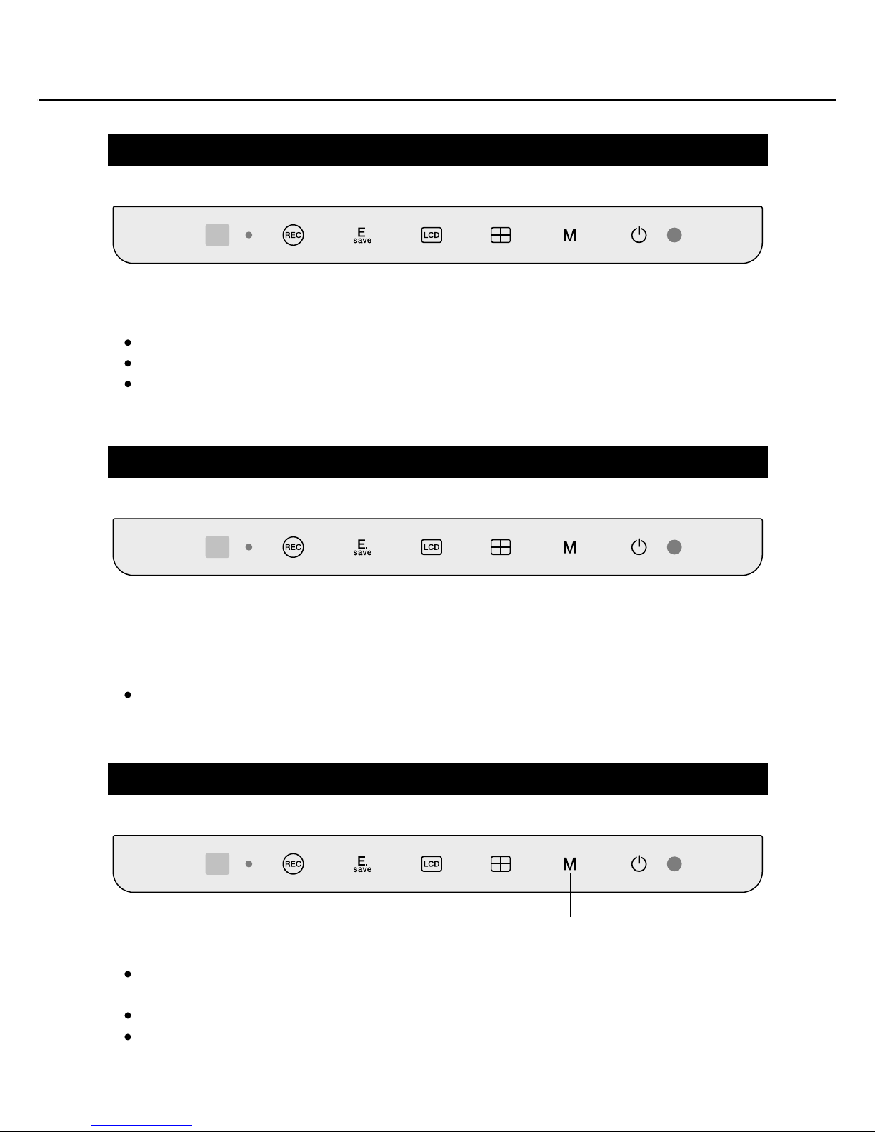
LCD Button (Screen ON/OFF)
Screen Switch (by Channel) Button
Channel moves in order as below when pressing the button.
( CAM1-CAM2-CAM3-CAM4-SPLIT1-SPLIT2-SPLIT3-NORMAL-CAM1... )
When LCD button is clicked, the screen is turned off.
When the button is clicked again, the screen is turned on.
The LCD is turned off automatically by setting Screen On Time
(See: Screen On Time, Page 21.)
Screen ON/OFF Button
Screen Switch (by Channel) Button
Main Menu Button (Menu Open/Close)
When you click [M] button on the front, six main buttons will be displayed on the
screen.(See: Main Menu Start, Page 13.)
If you click it again, Main Menu will be disappeared.
You can have Main Menu closed automatically by setting Menu Display Time.
(See: Menu Display Time, Page 13.)
Main Menu Button
8
Page 10
Components of the product
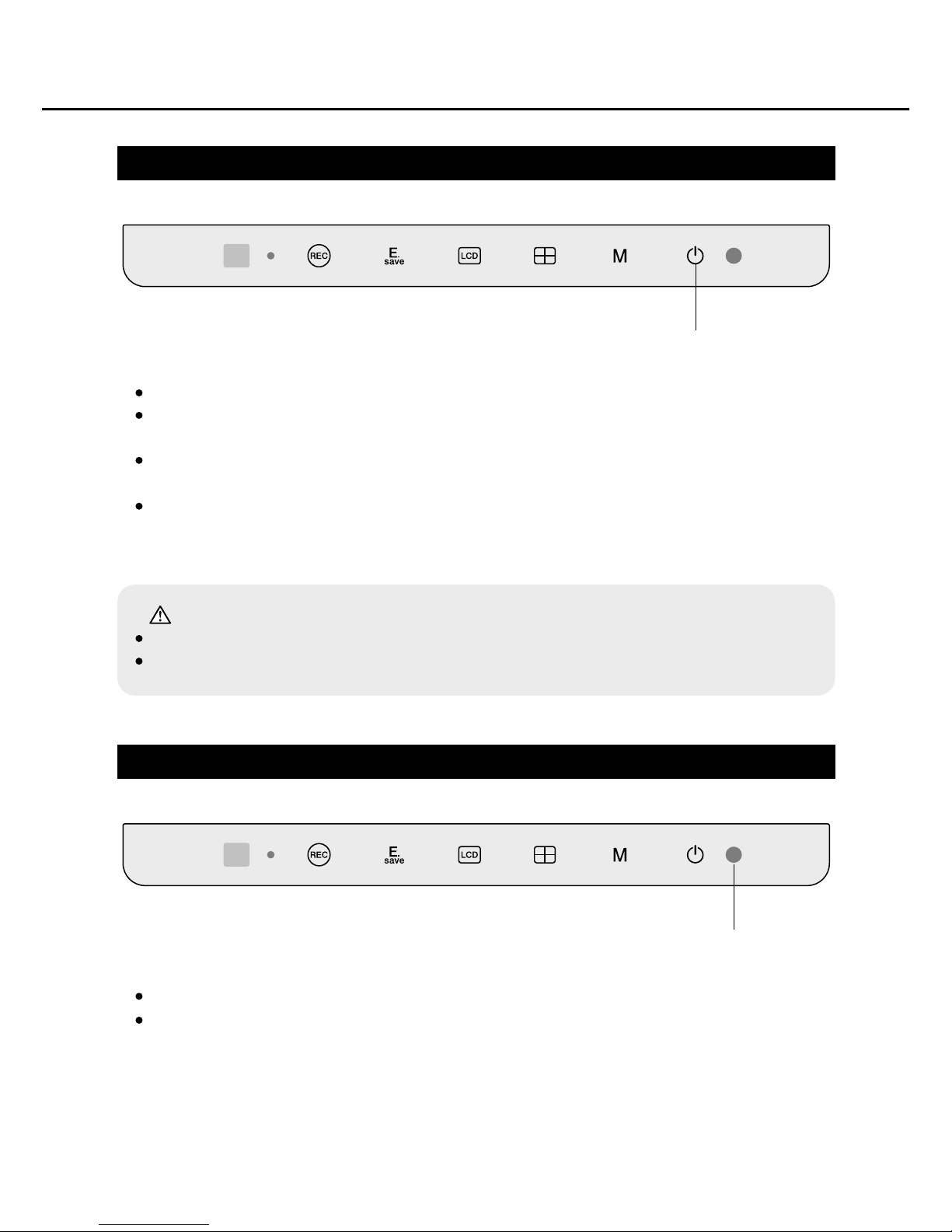
Power ON/OFF
illuminance sensor
This window is to setup sensor that detects brightness of the exterior of the car.
Set up Dimmer on Configuration to control brightness of the screen as you want.
(See: Dimmer, Page 22.)
Caution :
When turning the Power button on or off, it is not changed to the Parking mode.
Use the ACC On/Off button of the car if you want to have the Parking mode.
When you click the Power button, the device is turned on and starts booting.
When turning On/Off the power with Power button, it is not changed to the parking
mode.
Clicking the button at the parking mode turns on the screen and the mode will be
changed to the drive mode.
When you click the button when the power is on a pop-up window will be displayed
to ask whether to close the power or not. [Cancel] button helps to cancel closing
and [Yes] buttons closes the power.
Power ON/OFF Button
illuminance Sensor
9
Page 11
Start Screen
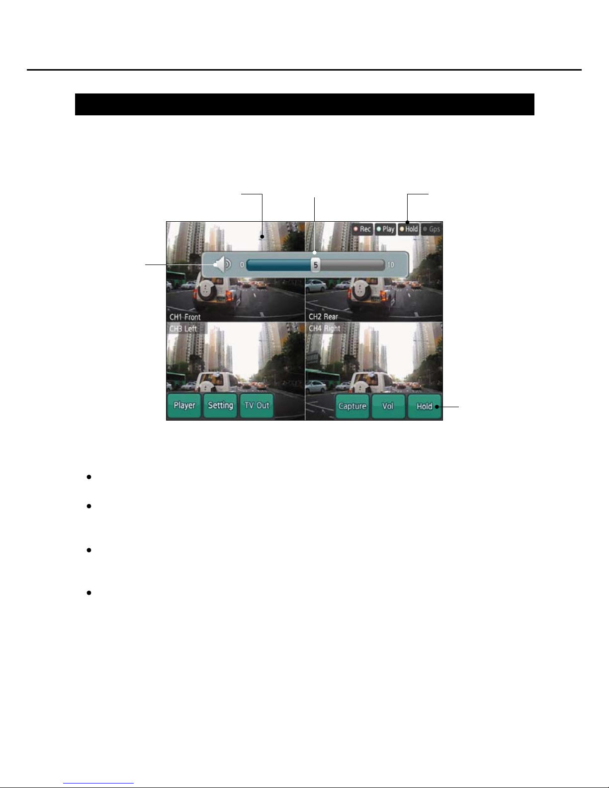
When the small windows on the multi screen are touched, the channel is
enlarged into the full screen. One more touch returns it to the multi screen.
Volume Pop-up : Volume control pop-up window
- Controls volume of the speaker
- The pop-up is disappeared after seconds when no operation is made.
Mute : Volume Remove Button
- Click it to mute or turn sound on.
- If you control the volume, you can turn sound on again.
Performance Indicator.
- Rec: indicates camera recording.
- Play : indicates 'play' of a recorded file
- Hold : indicates 'holding' of Key & Touch Screen.
- GPS : indicates that GPS signals are being received.
When the booting is over, the multi screen as below will be displayed.
When the small window is
touched, it is enlarged
Volume pop-up
Indicator
Mute
How to use the product
Main Button
10
Page 12
Main Menu Start
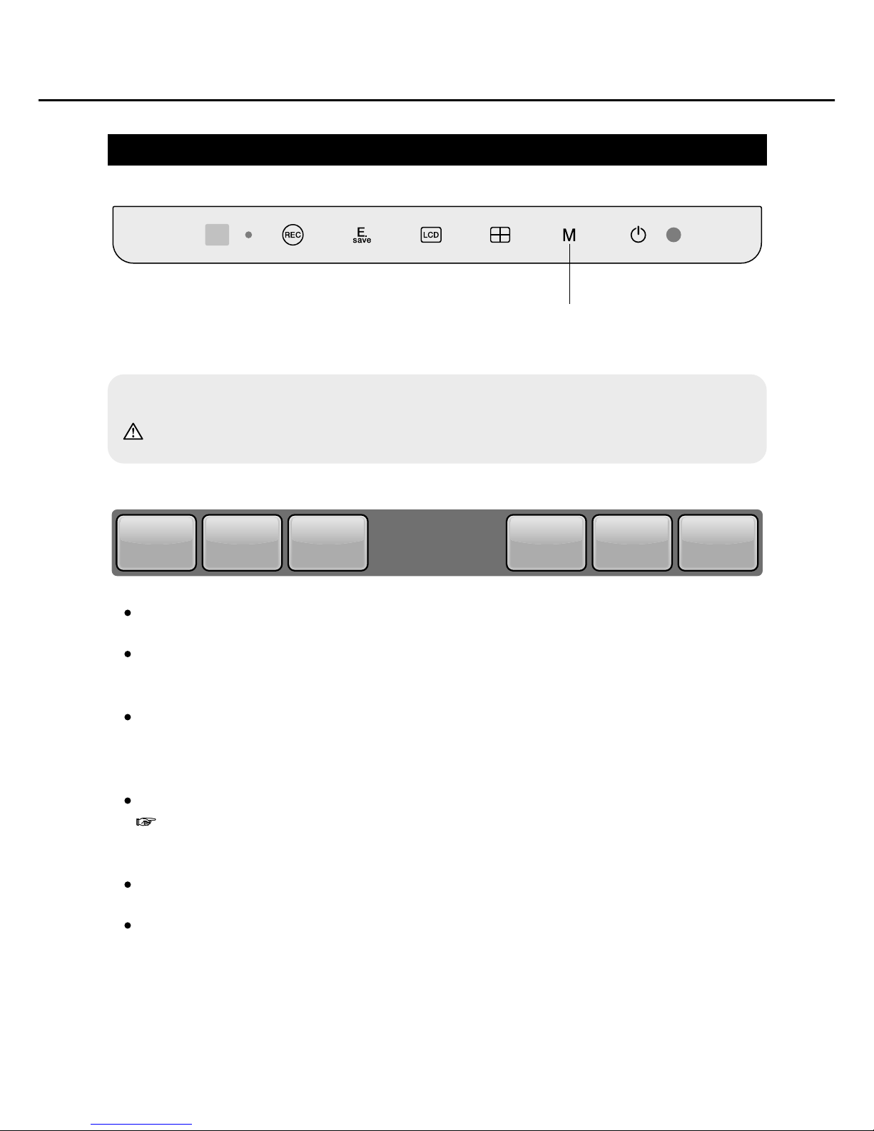
Player : Opens Player Mode and plays a recorded file.
Setting : Opens Setting Mode. If needed, you can change settings of recording/
screen/memory/system configuration.
TV Out : Outputs images and sound to TV monitor when Preview screen and recorded
files are displayed.
(TV Out Cable should be connected to TV Monitor)
Capture : Saves the displaying in Capture folder.
Ref.: Menu button is excluded. Images and the relevant information including
date are saved.
Vol : Turns on or off volume control pop-up window.
Hold : Holds the functions of Key & Touch Screen except [M] button on the front.
Main Menu Button
How to use the product
※When [M] button on the front is clicked, six main buttons are displayed.
Caution: You cannot get Player and Setting Mode during recording.
PlayerPlayerPlayer SettingSettingSetting TV OutTV OutTV Out CaptureCaptureCapture VolVolVol HoldHoldHold
11
Page 13
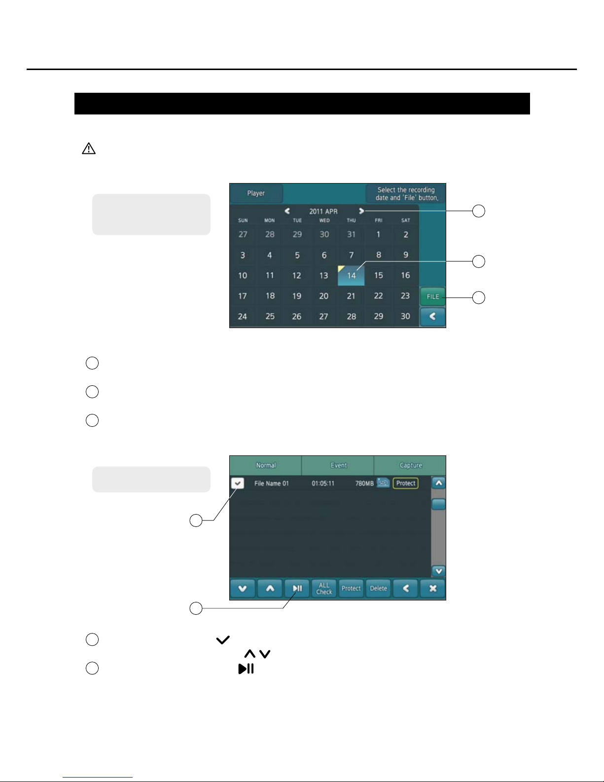
Player (Play of recorded files)
Select year/month recorded by clicking left/right arrow button.
If any recorded file is in the selected year/month, the number button will be activated.
Select a date by clicking the Date button.
You can select multiple dates if more recorded files were saved on different dates.
If you click the File button, a file list will be displayed as below.
When the Player button is clicked, the calendar is displayed as below.
Caution: You cannot record anything while Player is being executed.
How to use the product
1
3
2
To find a recorded
file on the calendar
File list
1
2
3
When the checkbox ( ) in front of the file name you want to play is clicked, the
file is selected displaying ( ) icon. (Multiple files can be selected.)
When play/pause button( ) is clicked, the selected file is played.
4
5
5
4
12
Page 14
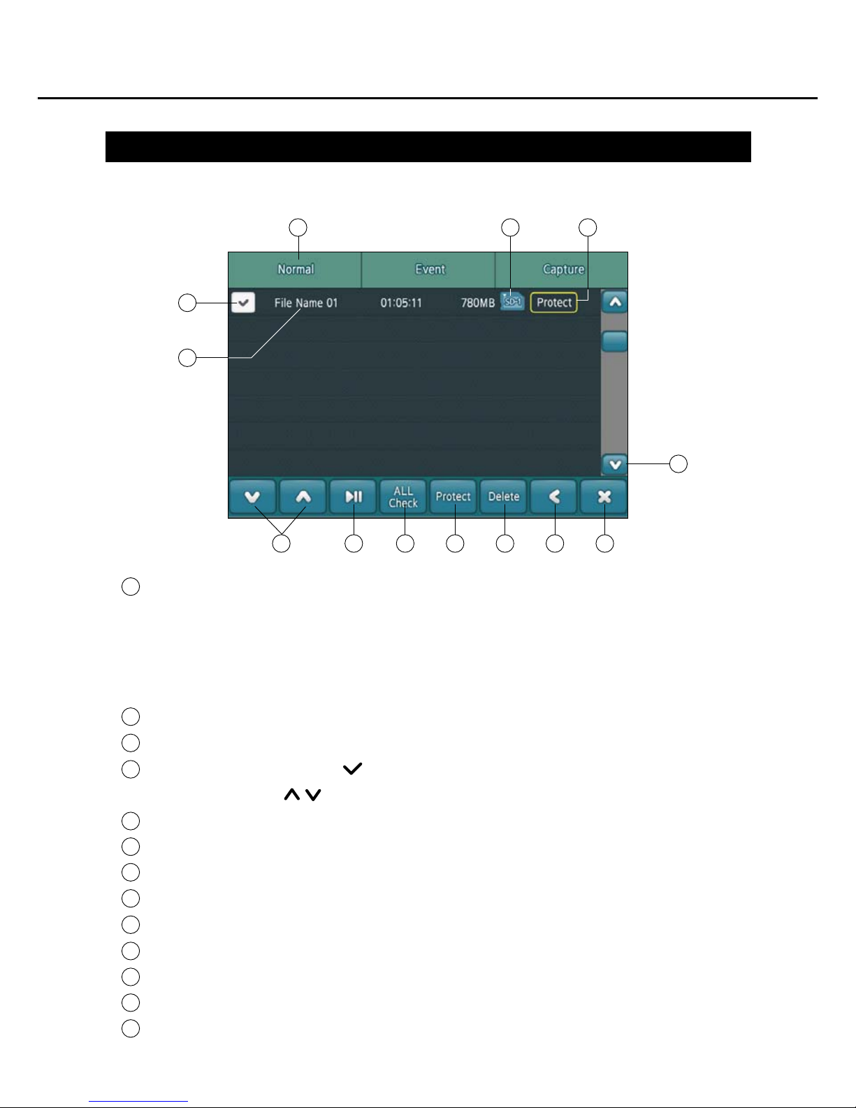
Player (Play of recorded files)
Recorded files are categorized and saved in three folders on the top.
- Normal : Normal video clips are saved in this folder.
- Event : Event video clips which were recorded by E.save button, G.sensor or
Motion Detection are saved in this folder.
- Capture : Captured image files are saved in this folder.
Click on the icon to see the numbers of SD Card in which files are saved.
File Protect : Click this button to see the files that are protected from deletion.
If you click the checkbox ( ) in front of the file name that you want to play, the file
is selected while ( ) icon is displayed.
Recorded file name/ recorded time/ file size are displayed.
Previous/next page is displayed by moving the file list upwards or downwards.
Play the selected file. Click again for pause.
All files on the list are selected on the check-box.
Set or cancel 'Protect' to protect a file from deletion.
Delete the selected file on the check box. Protected files cannot be deleted.
Return to the previous page.
Terminate the Player.
Go to previous/next page by moving the file list upwards or downwards.
The functions of the buttons on recorded file list are as shown in the below figure.
How to use the product
1
2
3
4
5
6
7
8
9
10
11
12
13
1
4
5
6 7 8 9 10 11 12
2 3
13
13
Page 15
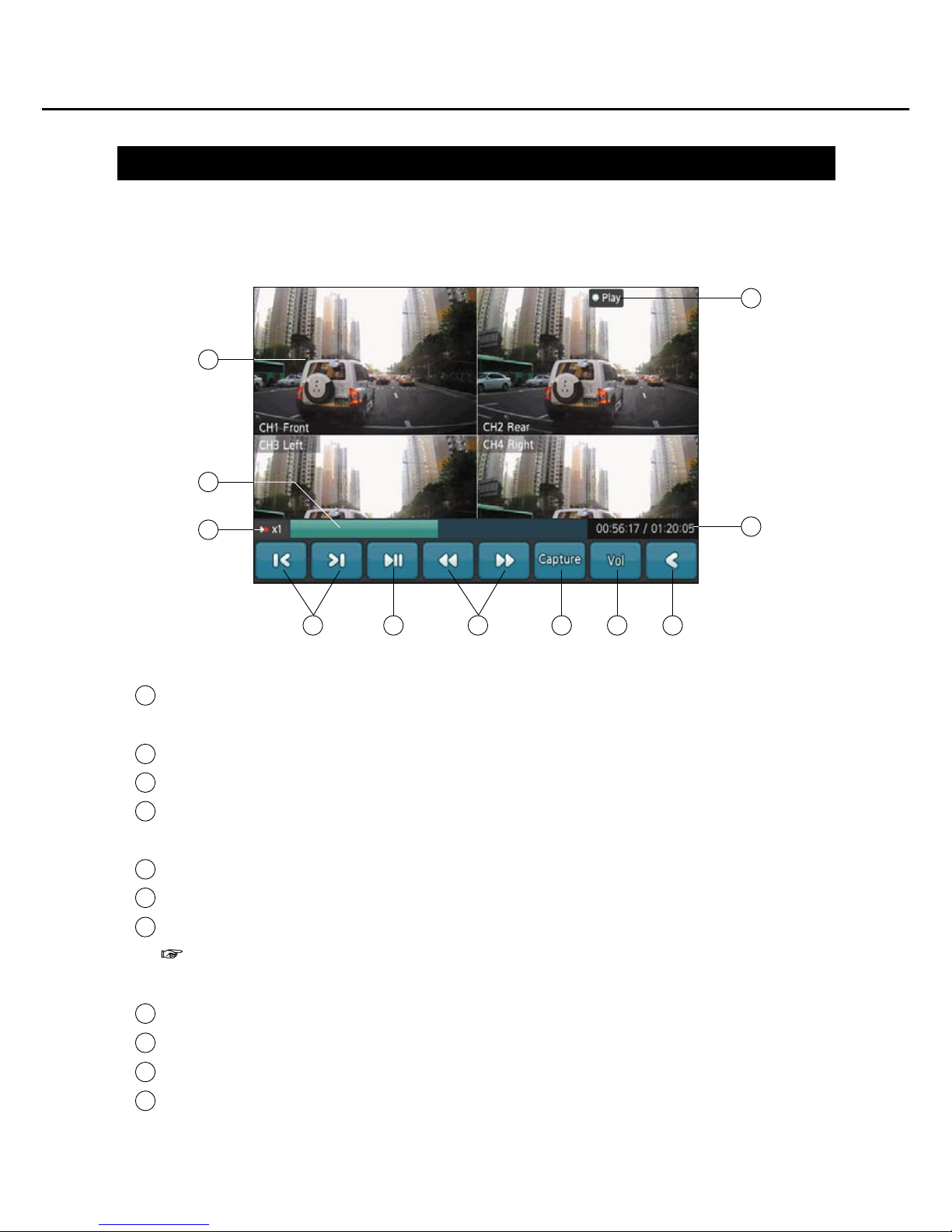
Player (Play of recorded files)
When the small window at each channel get touched, the small window is enlarged
into the full screen. If you touch the screen again, it is switched to multi screen.
Displays playing speed.
Selects previous/next file to be played.
The bar shows which part of the clip is being displayed on the screen. If you touch
the middle of the bar, you can start the clip as you want.
Starts playing a file. If you click once more, the screen will pause.
Controls the playing speed either slower or faster.
The ongoing image on the screen is saved as JPG in Capture folder.
Ref. : Menu button image is not saved but images and the relevant information
including date are saved.
Vol : Turns on or off volume control pop-up window.
Returns to the previous page.
The recorded time of the displaying scene and total recording time are shown.
Informs that a recorded file is being played.
The functions of the buttons on recorded file list are as shown in the below figure.
How to use the product
1
2
3
4
5
6
7
8
9
10
11
1
4
3 5 7 8 9
11
10
2
6
14
Page 16
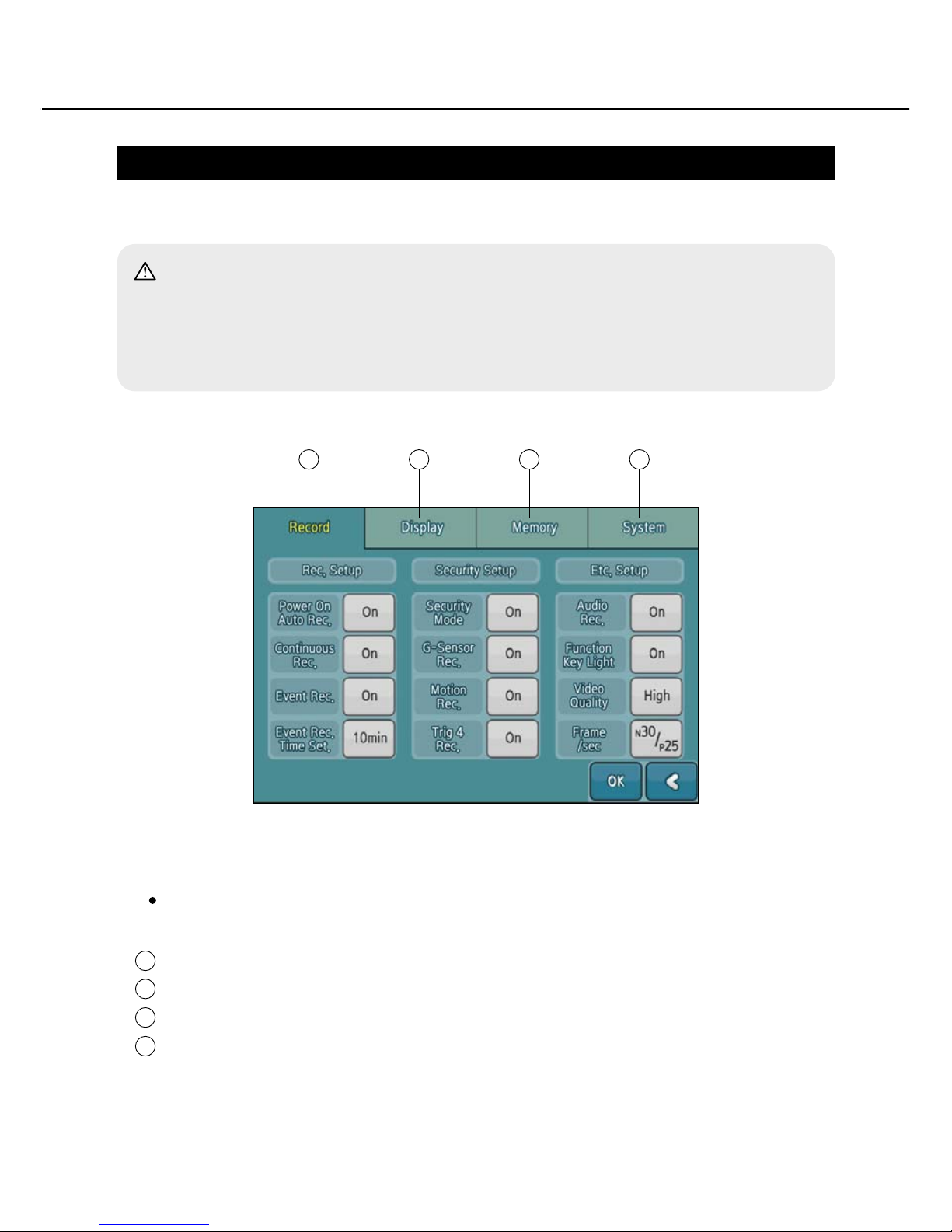
Setting (Configuration)
Setting menus are categorized into 4 tabs on the top of the screen.
Record : Recording-related setting.
Display : Display-related setting.
Memory : You can see memory of the card or format the SD card.
System : You can set system-related configuration or see the conditions
If you click Setting button on the Main Menu, the below screen will be displayed.
How to use the product
1
2
3
4
Caution:
-You cannot execute any of Normal/G-Sensor Impact/Motion Detection/E.Save
button recording during configuration setting.
-If you were recording something, the recording will stop and configuration screen
will be displayed instead.
1 2 3 4
15
Page 17
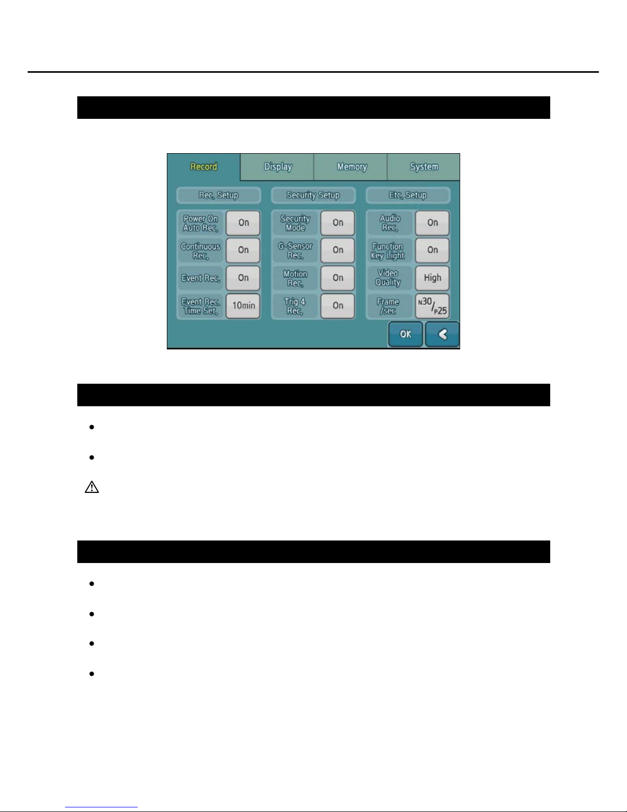
Record Setting
How to use the product
Power On Auto Rec. (Automatic Recording)
Power On Auto Rec. On: When DC 12V ~ 24Vvoltage power is supplied to ACC
wire, the Drive Mode is turned on, starting automatic recording.
Power On Auto Rec. On: Even if When DC 12V ~ 24V voltage power is supplied
to ACC wire and the Drive Mode is turned on, it does not start automatic recording.
Caution: If you want to turn the ACC on and start recording of the driving situation,
you should set the Power On Auto Rec 'On'.
Continuous Rec.(Continuous Recording Setting)
On : Saves files consecutively while deleting files from the early saved file(s) when
the storage is full.
Off : A pop-up window that informs the storage is full is displayed and the recording
is stopped.
If the storage is full, recording is stopped. Delete the old files and check if old files
are set to be deleted automatically.
Set 'Protect' not to delete or backup important files to your PC.
(See: File Protect, Page 15.)
16
Page 18

Event Rec (Event Recording Setting)
How to use the product
On : Starts recording by selecting [E.Save] and [G.Sensor] buttons on the Drive
Mode. (can be operated with Normal Recording simultaneously.)
Ref:
Normal Recording is recording on the Drive Mode (by clicking REC button, or by
selecting Power On Auto Rec setting / See: Power On Auto Rec, Page 18.)
Off : Recording by [E.save] button and/or [G.Sensor] impact is not executed on the
Drive Mode.
Note : Be aware that all recording functions if you do not execute normal recording
Event Rec. Time Set (Event Recording Time Setting)
Sets time of recording by pressing E.save button or choosing G.Sensor Impact on
the Drive Mode.
You can set one out of five from 15 min to 10min.
Total running time includes both, time before & after the event, displayed on the
button.
Ex) When you set 1min, you can record total 2 minutes, 1 min before the event and
after the event respectively.
Security Mode (Parking Mode Setting)
On : When the ACC of the car is on, you can operate Parking Mode.
Off : When the ACC of the car is off, the power of the device is turned off.
Caution: If you set it 'Off', you cannot have the Parking Mode as the power is turned
off. (Be careful in selection as you cannot record the parking situation.)
You can record for around 15 seconds of an event, using Motion Detection,G-Sensor,
and the door sensor on Parking Mode. In addition, you can record several events
occurred consecutively.
Ref: Check settings of Motion Detection, G Sensor, and Door Sensor.
G-Sensor Rec.: Sets Event recording through G Sensor.
Motion Rec. : Sets Event recording through motion detection.
Trig.4 Rec. : Security Mode, select whether to Trig.4 event recording will be.
(See: Trigger 4 Recording, Page 26.)
17
Page 19

Etc. (Other Settings)
How to use the product
Audio Rec.
On : Records sounds with images.
Off : Records only images not sounds.
Functon Key Light.
On : Uses Rec LED and Key light on the front panel.
(Rec LED and Key light are turned on/off when the screen is turned on/off.)
Off : Rec LED and Key light are kept off.
Video Quality
Sets the recording quality to High/Normal/Low.
( Ref: 7. Specification, Page 38.)
Frame/sec.
Sets a number of frame per second.
Changes a number of frame by clicking digit buttons.
Caution: Click [OK] button to save modified settings.
18
Page 20
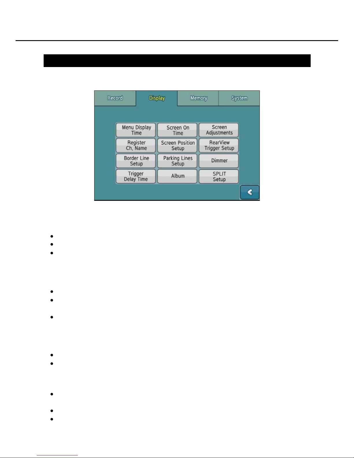
Display Setting
How to use the product
Menu Display Time
Sets up time for menu to disappear automatically
If you set 'On', the Menu will automatically remain on the screen.
If you set up time, Menu will be displayed. If you do not operate any button within a
given time, Menu will be automatically disappeared.
Screen On Time
Sets up time for the screen to be turned off automatically.
At On setting, the screen is not automatically turned off.
(But, the screen will be turned off if you touch [LCD] button on the front panel.)
If you set up time and the screen will be on. If you do not operate any button within
a given time, the screen will be automatically tuned off.
Screen Adjustments
Brightness : Sets brightness of the screen from 0 to 10 level.
Contrast : Sets contrast of the screen from 0 to 10 level.
Register Ch. Name
Ch. Name Change : Registers or Modifies channel name.
(Channel name is basically displayed Cam.1~4.)
Display Ch. Name On : The channel name is displayed on the screen.
Display Ch. Name Off : The channel name is not displayed on the screen
19
Page 21

How to use the product
Screen Position Setup
As shown in the below picture, you can designate the location of images on the multi
screen for each camera. [See picture]
Ch.4, 5 Change : If you choose Option #5 camera for the location of images taken
by No.4 camera, the cameras will be switched as you input. The basic input is Cam.4
but images taken by Cam.5 will be displayed when you choose Cam.5.
RearView Trigger Setup
Images taken by cameras that detected trigger signals, (1) can be displayed on the
multi screen, or (2) only one image can be displayed on the full screen.
Just as at Screen Position Setup, other cameras can be chosen for each trigger than
the camera which was numbered identically with the trigger though the basic input
is Trigger #1/CAM1, Trigger #2/CAM2, and Trigger #3/CAM3 and Trigger #4/CAM4.
Border Line Setup
Thin : Border lines between the screens of multi channels are illustrated in a thin line.
Thick : Border lines between the screens of multi channels are illustrated in a thick line.
None : No border lines between the screens of multi channels are displayed.
Parking Lines Setup
Display : Parking lines are displayed on the screen of the channel which detected
trigger 1~4 signals.
Calibration : Location of the parking lines is adjusted.
Thin : Parking lines are illustrated in a thin line.
Thick : Parking lines are illustrated in a thick line.
Ref. : Parking lines are displayed only when the channel which detected trigger
signals is shown in full-screen mode.
Dimmer
On: Brightness of the screen is automatically adjusted to brighter or darker by detecting
the brightness of outside the car through sensitivity sensor on the front panel.
Off: The brightness that was set on the [Screen Adjustments] menu is maintained.
Trigger Delay Time
Trigger 1~4 signals delay time of 0-9 seconds is set.
Album
When On is chosen, photos in the album will be displayed after 30 seconds.
When you set up time for slide shows, the photos will be displayed in consecutive order.
Photos in the album should be saved in No.1 'Album' folder of the SD card via the
computer. If Off is chosen, no album will be executed.
Caution : Do not forget to click [OK] button to save modified settings.
20
SPLIT
Configure the screen of SPLIT 1 / 2 / 3
The selected SPLIT modes are displayed at "Speed switch CH selection" and
"Screen switch button selection".
Page 22
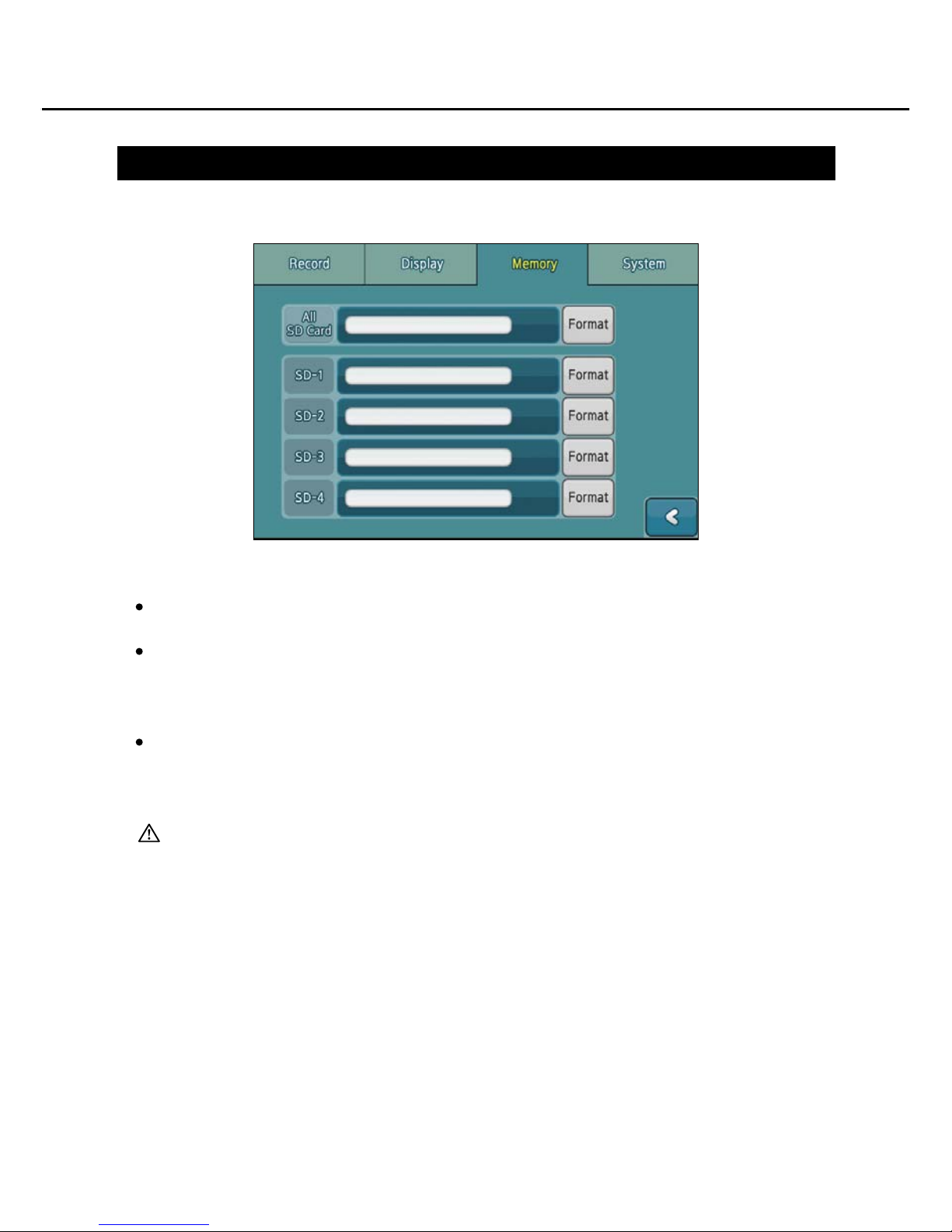
Memory Setting
How to use the product
All SD Card : The size and the occupied capacity of the SD cards placed at all 4
slots are displayed.
SD-1~4 : The size and the capacity of a SD card allocated to a slot are displayed
respectively.
Ex) SD-1 :No.1 SD card
Format : Formats SD card.
- All SD Card : All placed cards are being formatted simultaneously.
- SD-1~4 : Only one card allocated to the number is formatted.
Caution : Do not forget to backup all necessary files in your PC before you start
to format as all data in the SD card are deleted by format.
21
Page 23
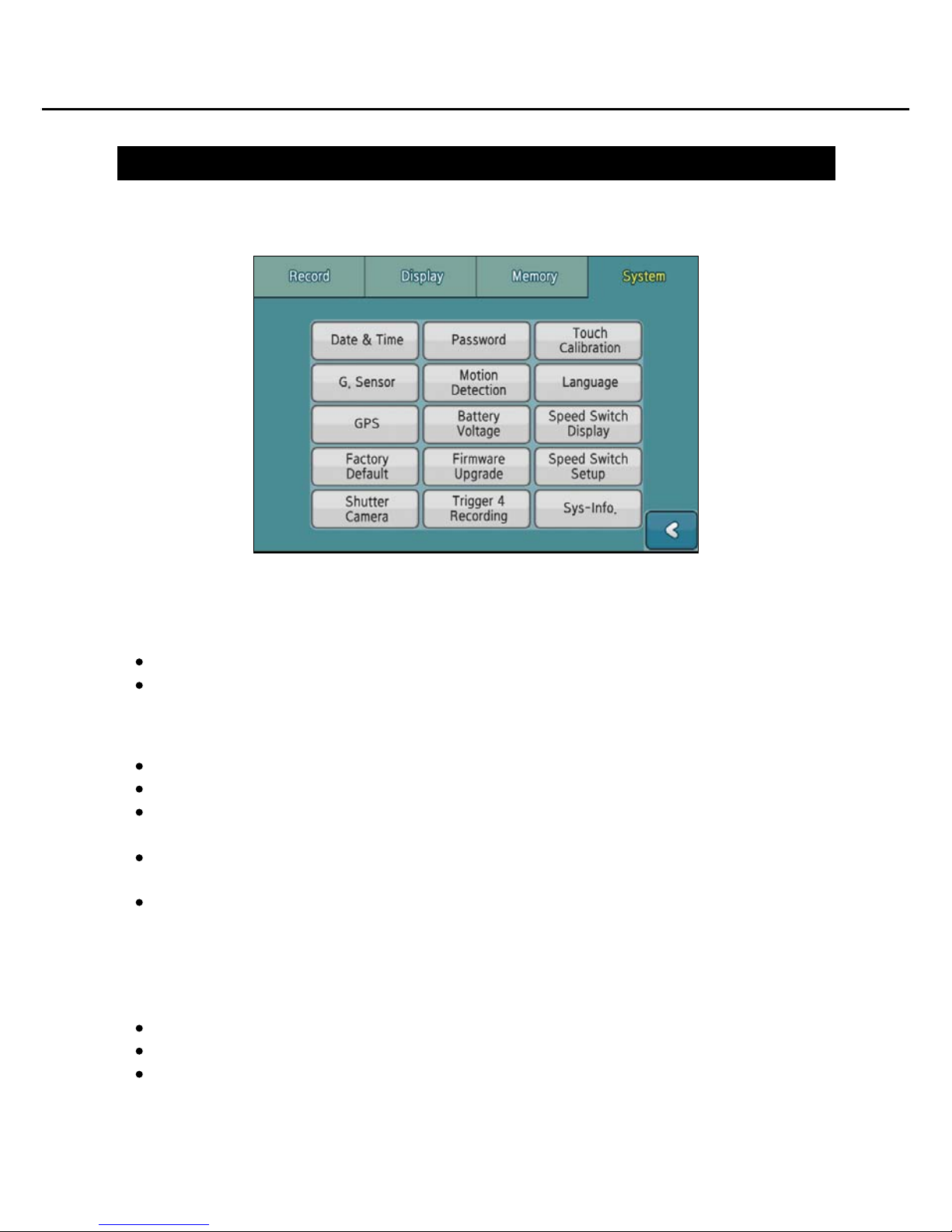
System Setting
How to use the product
Date & Time
Set date and time.
Date Format / Time Format: Select a display type of date and time.
Password
You can set up/cancel/modify a password for accessing Setting page.
If you touch the white area to input a password, the software keyboard will be displayed.
Input [New Password and Confirm Password] and click [Lock] button to register a
new password.
After you register a password, you should input the registered password on the main
screen to access [Setting] page.
Re-access to [Setting-Password] to cancel or modify the registered password. Input
[Current Password] and click either [Change] or [Unlock] button to modify or cancel
the password.
Touch Calibration
Corrects the calibration on the touch screen.
Revises if a button is not properly touched on the screen.
If you click [+] icon as shown in the picture for seconds, you can have it revised.
22
Page 24

System Setting
How to use the product
G.Sensor
Set sensitivity of impact level for G.Sensor recording.
Choose one out of Sensitive / Normal / insensitive.
Set it Normal and make sure that event recording is executed by the impact of door
slam while the car is stopped. If you want to record by weaker motion, set it [Sensitive].
If you want to record by stronger motion, set it [Insensitive] .
Ref. : The input is automatically modified not to execute G.sensor recording by
normal motion of the car on the Drive Mode.
Caution : As impact sensitivity during driving may be different depending on car
type and condition, you should adjust impact sensitivity properly for the
car. The impact detection sensor is installed in the DVR. Be aware that
the impactive moments are not recorded if this device does not detect
the impact occurred in the car.
Motion Detection
Set sensitivity of motion for recording to 'Motion Detection' on the Drive Mode.
Choose one out of Sensitive / Normal / insensitive.
Set it [Insensitive] and check if the event is being recorded when a person walk at
1m distance from the camera while the car is stopped. Set it [Normal] if you want
further detection. Set it [Insensitive] when you want to execute motion detection
recording of a person who is over 5m distance away.
Ref. : On the Drive Mode, motions are not detected.
Language
Select a language of menu.
GPS
Check if the GPS signals are being received.
Satellite Position(GPS satellite position), Satellite Signal(GPS signal strength),Latitude
Longitude, Altitude, and Speed, as well as Date and Time are displayed.
Battery Voltage
The voltage of the car batteries and the back-up batteries in the device are displayed
(Ref: Battery Voltage, Page 26.)
23
Page 25
System Setting
How to use the product
Speed Switch Setup
Speed Switch On/Off.
Frequency Setting : 10~200 Hz.
Caution : Speed switch On, [Menu] button and [Setting] button, you will operate.
Speed Switch Display
Under Freq. : Select the normal screen or Cam1~4 screen or SPLIT1~3.
Over Freq. : Select the normal screen or Cam1~4 screen or SPLIT1~3.
Over Freq. Display : Select the LCD on or off
Factory Default
Modified values on the Setup page are initialized to the original factory values.
The system is rebooted after initializing.
Firmware Upgrade
Firmware is upgraded.
A file to be updated must be saved in No.1 SD Card and then updated.
During updating of the product, do not pull the SD card out nor turn the power off.
If you pull the card out or turn the power off while updating, it may cause an error
or failure of the product or performance.
Shutter Camera
No shutter/heater : Use the normal camera.
Shutter/heater by Power ON : Use the normal camera & shutter camera
Shutter/heater by Trigger : Only Use the shutter camera
Trigger 4 Recording
Screen Only : Only the Trig.4 Screen
Event Rec. : Event Recording.
Sys-Info.
The Firmware version and model name of the product are displayed.
Caution : Do not forget to click [OK] button to save modified settings.
24
Available to set per channels.
Page 26
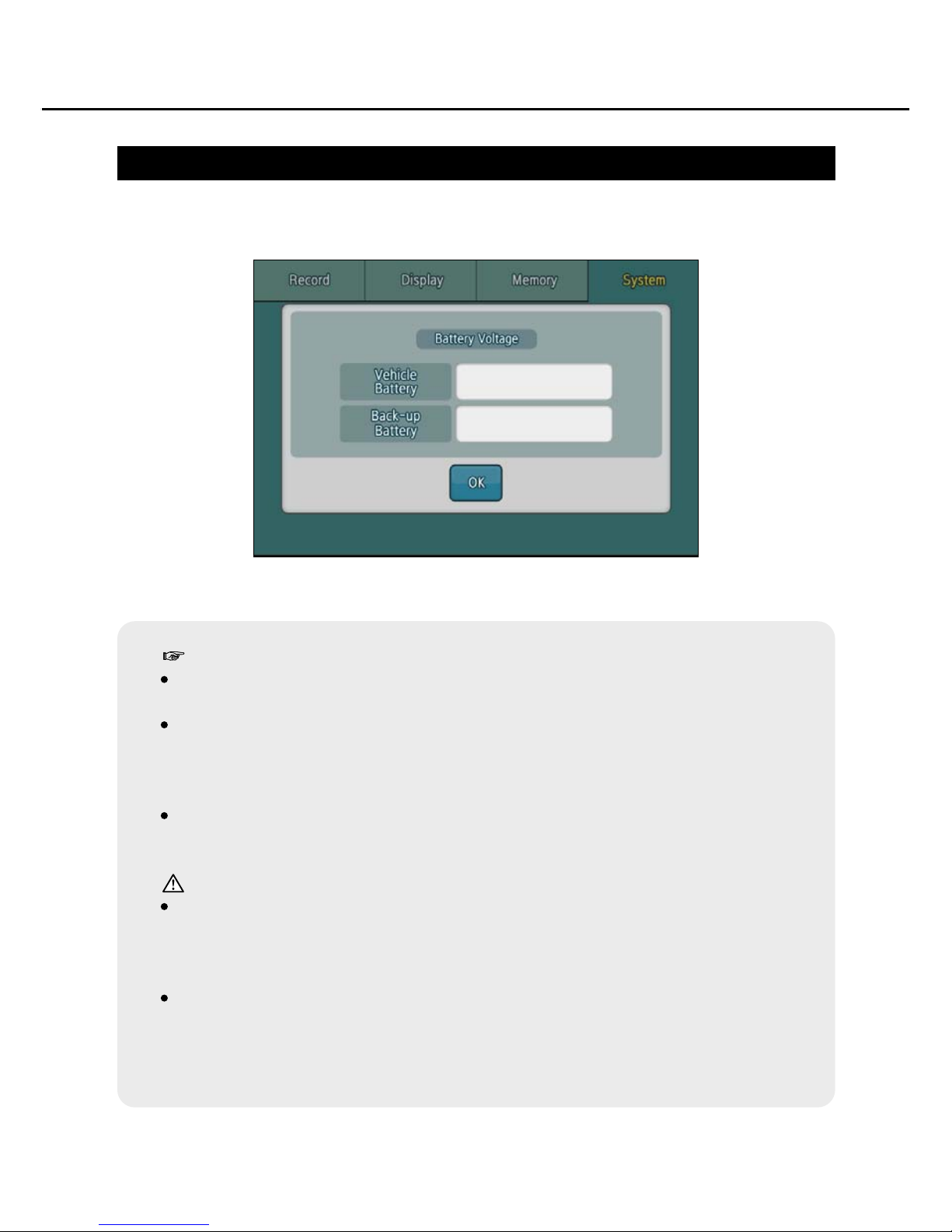
Battery Voltage Check
How to use the product
Battery Voltage the car batteries and the back-up batteries.
Reference :
Low voltage detection (for protection of battery discharge)
Vehicle voltage : If the battery voltage drops to 11.5volt(12volt battery) /
22volt(24volt battery), the entire operation is stopped and the power is
automatically turned off.
Back-up battery : If the battery voltage drops to 7volt, the entire operation
is stopped and the power is automatically turned off.
Caution:
You should fully charge the batteries for car which has less than 2 hours
drive a day. If you drive your car less than 2 hours a day, the batteries are
likely to be discharged as they are not fully charged.
Operating time of the DVR may be different depending on voltage setting,
battery capacity and conditions. Before installing the DVR, replace the
batteries if the condition of the batteries is not good. We recommend you
to replace it with the largest batteries which can last longer and fit the car.
25
Page 27

Basic Components
Main Device
Summarized Guide
Camera Cable
Power & Sensor Cables
Holder (Angle Mount Type)
Sun visor
Wrench
Clamping Screws
SD Card Cover Key
Options
SD Card (Sandisk 32GB)
GPS Antenna
Camera Extension Cable
Holder (Free Mount Type)
Camera
Components
How to install the product
26
Page 28
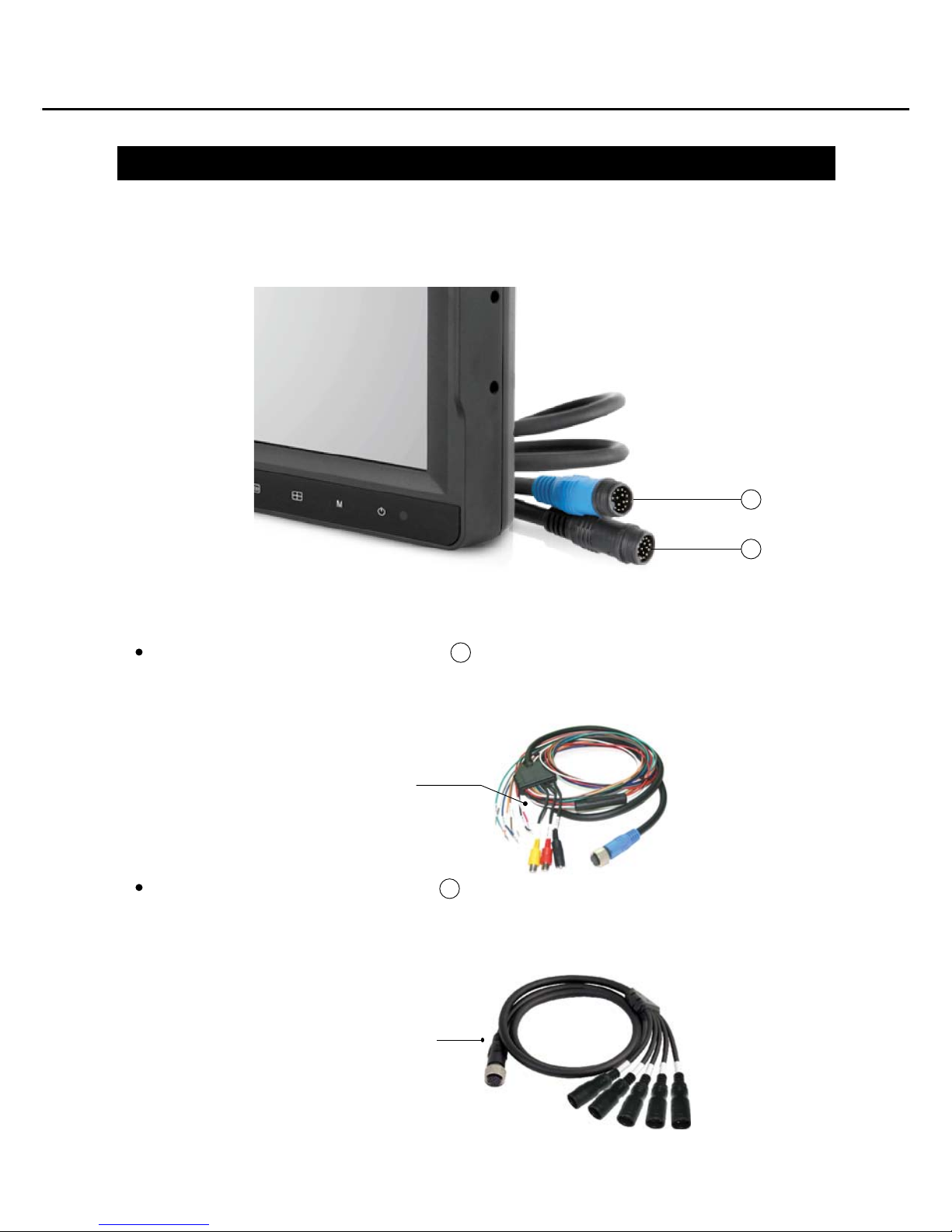
Power cable and camera cables
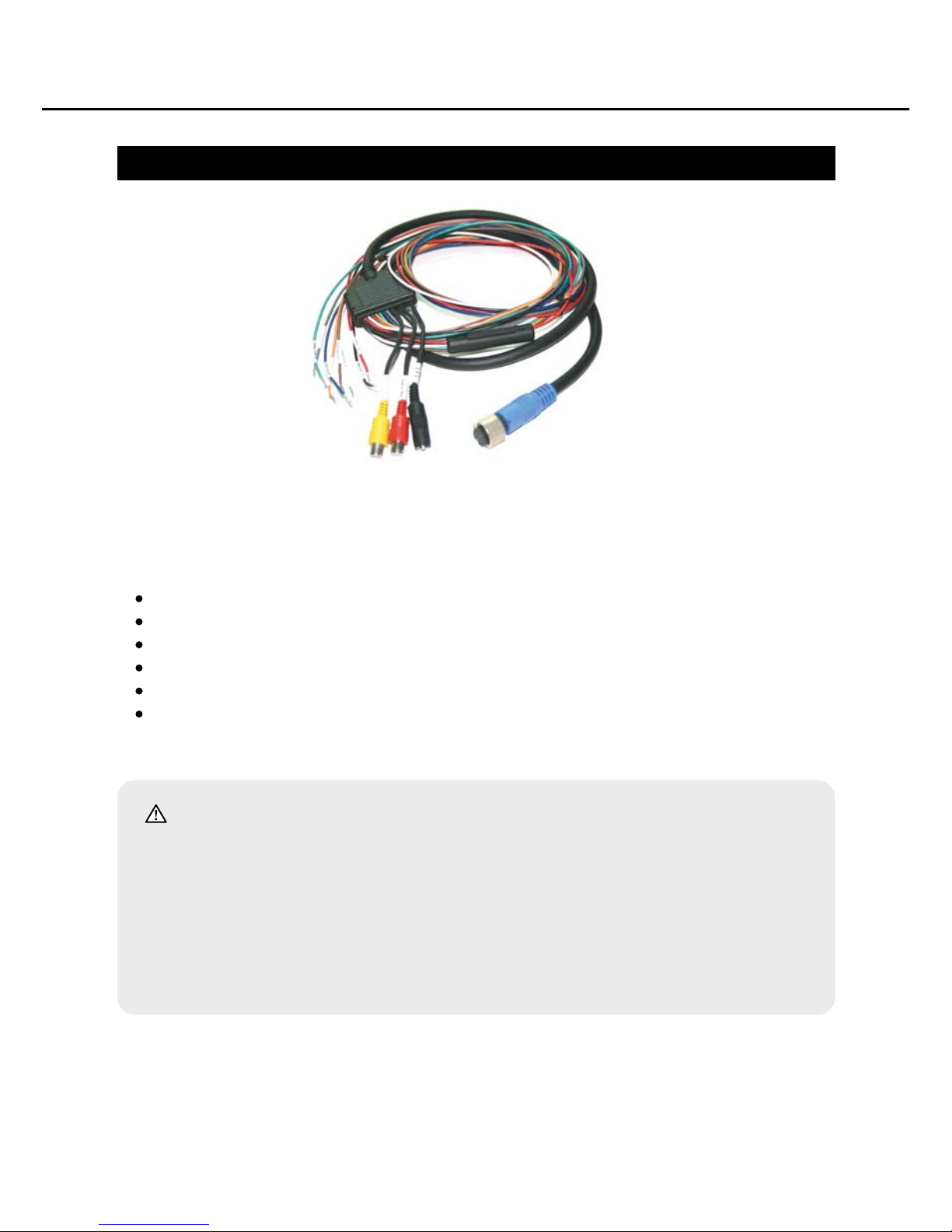
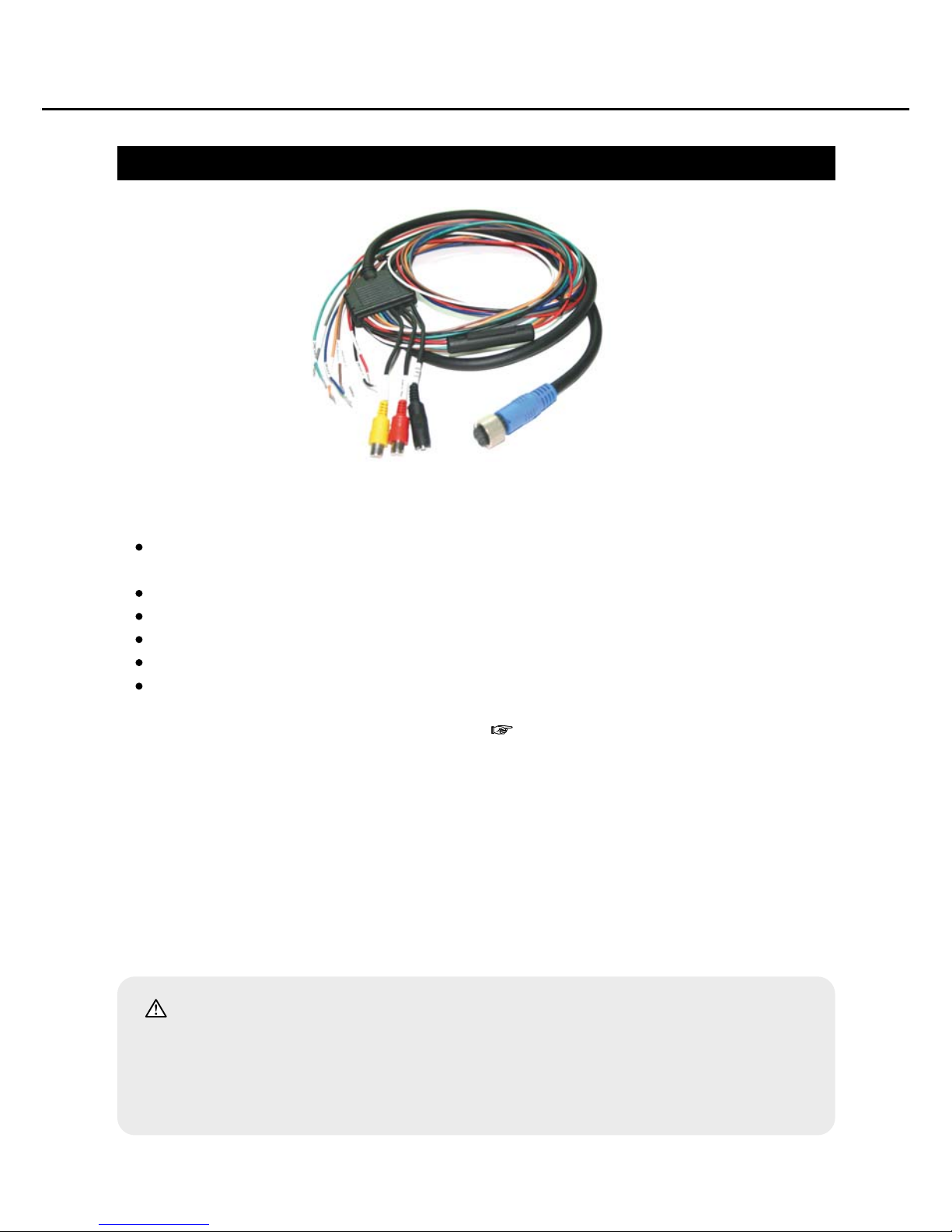
A power cable and two camera cables are included in this product. You will the
different cables as below.
11
12
11
12
How to install the product
The power cable is in blue sheath. ( )
The power cable includes GPS, TV Out, and camera trigger wires.
Connect the power cable to the blue socket of the device.
Camera Cable is in black sheath. ( )
Connect the camera cable to the black socket of the device.
Power Cable (Blue Socket)
Camera Cable (Black Socket)
27
Page 29
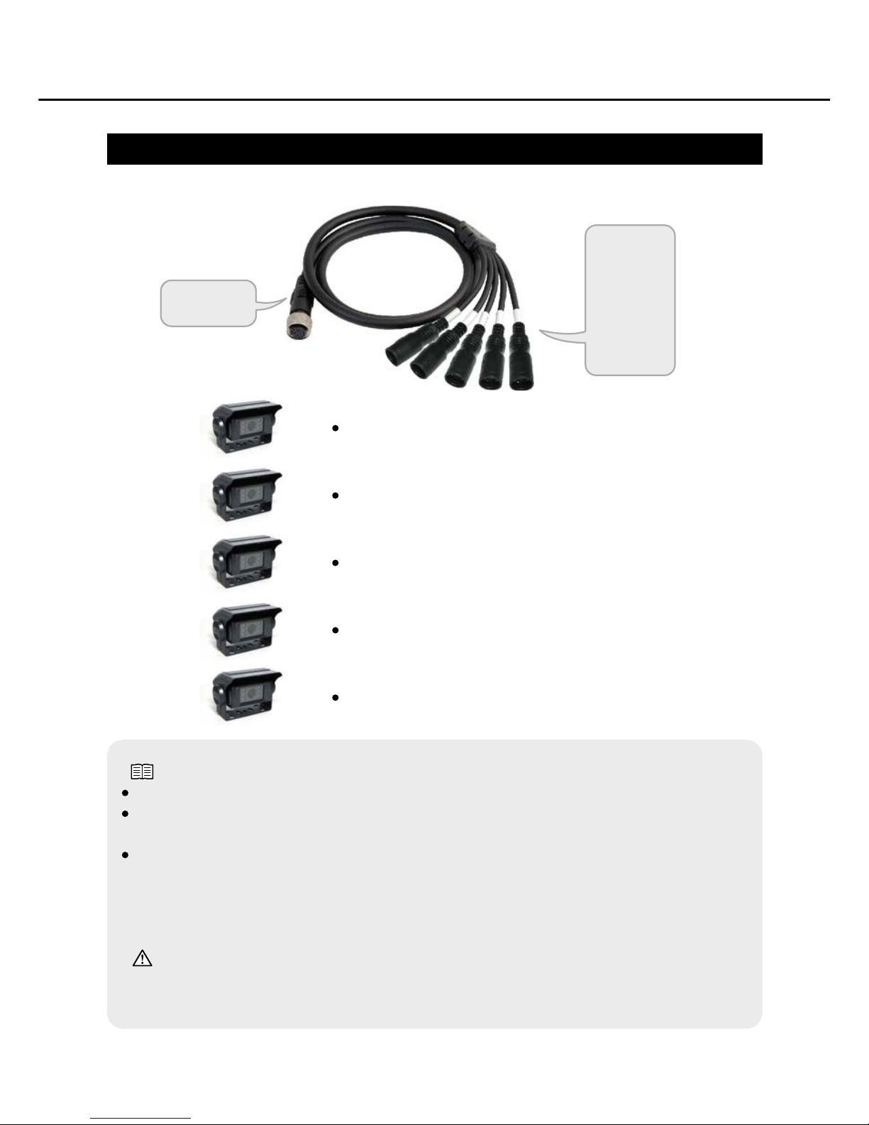
Camera Cable Connection
How to install the product
To DVR
CAM1
CAM2
CAM3
CAM4
CAM5
Connect No.1 camera to CAM1 socket.
Connect No.2 camera to CAM2 socket.
Connect No.3 camera to CAM3 socket.
Connect No.4 camera to CAM4 socket.
Connect No.5 camera to CAM5 socket.
Note for installation:
Camera is automatically detected in the initial operation when the power is turned on.
You should number the cameras from 1 to 5 considering features of the cameras
if they are all different.
Camera #5 is an option. To use No.5 Camera, you should switch No.4 Camera to
No.5 Camera at Screen Position Setup. In addition, No.5 Camera does not support
voice recording but only image recording.
(See: Screen Position Setup, Page 22.)
Caution:
Make sure that the power of the device is off before connecting a camera.
Do not connect it when the power is on. It may cause a failure.
28
Page 30
Wire Connection
How to install the product
Wire Connection
BATT (Red wire) : Connect it to + terminal of the battery.
GND (Black wire) : Connect it to
-
terminal of the battery or the car itself.
ACC (Brown wire) : Connect it to ACC of the car.
The recommended input voltage for power is between DC 12V ~ 24V.
The recommended input voltage for ACC wire is between DC 12V ~ 24V.
When DC 12V ~ 24V voltage is supplied to ACC wire, (if the power is off)
the power is turned on or (if the power is off) it turns to driving mode.
Caution:
Make sure that the power is off before you connect the power wire. Check what
voltage of power is supplied to ACC wire of the black box for car when the ACC
power of the car is off (when you turn off the car engine and take the key out).
Make sure that the ACC power get totally blocked when the ACC is off.
(when you turn off the car engine and take the key out )
If the ACC power is not set to GND when you turned the ACC off, you have to
connect a relay to the ACC wire so that the ACC power of the car is not discharged.
29
Page 31
Connection of trigger wires
How to install the product
How to connect trigger wires
For the Trigger No.1~4 wires, connect signals of the cars in which CAM No.1~4
cameras were installed.
Trigger 1 (Orange wire) : Trigger wire for No.1 camera
Trigger 2 (Green wire) : Trigger wire for No.2 camera
Trigger 3 (Gray wire) : Trigger wire for No.3 camera
Trigger 4 (White wire) : Trigger wire for No.4 camera
Speed Switch (White wire) :
To detect the vehicle's speedometer is a wire.
You should set Speed Switch Setup.( Ref.: Speed Switch Setup, Page 26.)
DC 12V ~ 24V voltage is required to detect signals from each trigger.
For Installation Example:
Trigger1 : Should be connected to the rear gear signal.
Trigger2 : Should be connected to brake signal or drive, brake,
parking gear signals.
Trigger3 : Should be connected to the left blinker signal.
Trigger4 : Should be connected to the right blinker signal.
Caution:
Make sure that the power is off before you connect the trigger wires. Check if the
power is supplied to trigger wires while the ACC power of the car is off (when you
turn off the engine and take the key out). If you touch the water spills can cause
malfunction.
30
Page 32
How to install the product
GPS Antenna Connection
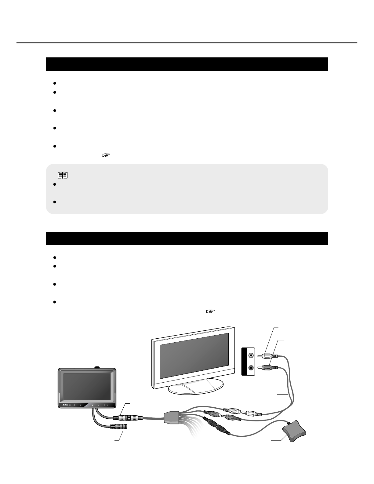
Connect GPS antenna to GPS socket.
The best way to install GPS antenna is to place outside (on a car roof), however it
can be placed near windows if it has to be installed in the car.
Please be aware of GPS errors occurred in certain circumstances and error range
is normally around or over 15m.
It may take long to receive GPS signals depending on the circumstances after it is
turned on.
When GPS signals are normally received, GPS indicator on the right on the screen
is activated. ( Ref.: Performance Indicator, Page 12.)
External Equipment Connection (TV out)
Connect the device to an external equipment to see recorded or replayed images.
Connect the voice cable to Audio Out socket and the image cable to Video Out
socket. And connect both to AV input socket of the external equipment.
The Display Format(NTSC/PAL) of DVR must be identical with the format of the
external apparatus.
When TV Out button on DVR is clicked, the AV will be outputted.
OSD is not outputted to external equipment.( Ref.: TV Out, Page 13.)
Note:
Only when GPS signals are received, GPS location information is saved in the
recorded image file.
Even though GPS signals are not receivable, recording will work normally.
※
Yellow (Video)
VIDEO AUDIO
Red (Audio)
GPS
AV-out Cable
Power cable(Blue)
Camera cable(Black)
GPS
GPS
GPS
31
Page 33

1. Connect the SD card to USB of PC via a card leader.
2. Install and execute the PC Player installed in the computer.
3. Click [Select Folder] button in the Function buttons of PC Player.
4. Choose a folder in which the file to be replayed is when the file search
window is popped up.
(For instance, click [D:\] if the SD card reader is in D drive.)
5. When a folder is chosen, the digits showing the recorded date on the
bottom calendar will be activated.
6. If you click the date, a list of recorded files will be shown on the right
window. (you can select multiple dates at once.)
7. When you double-click a recorded file, the file will be replayed on the
screen.
How to use Player
How to use PC Player
32
Page 34
PC Player Execution
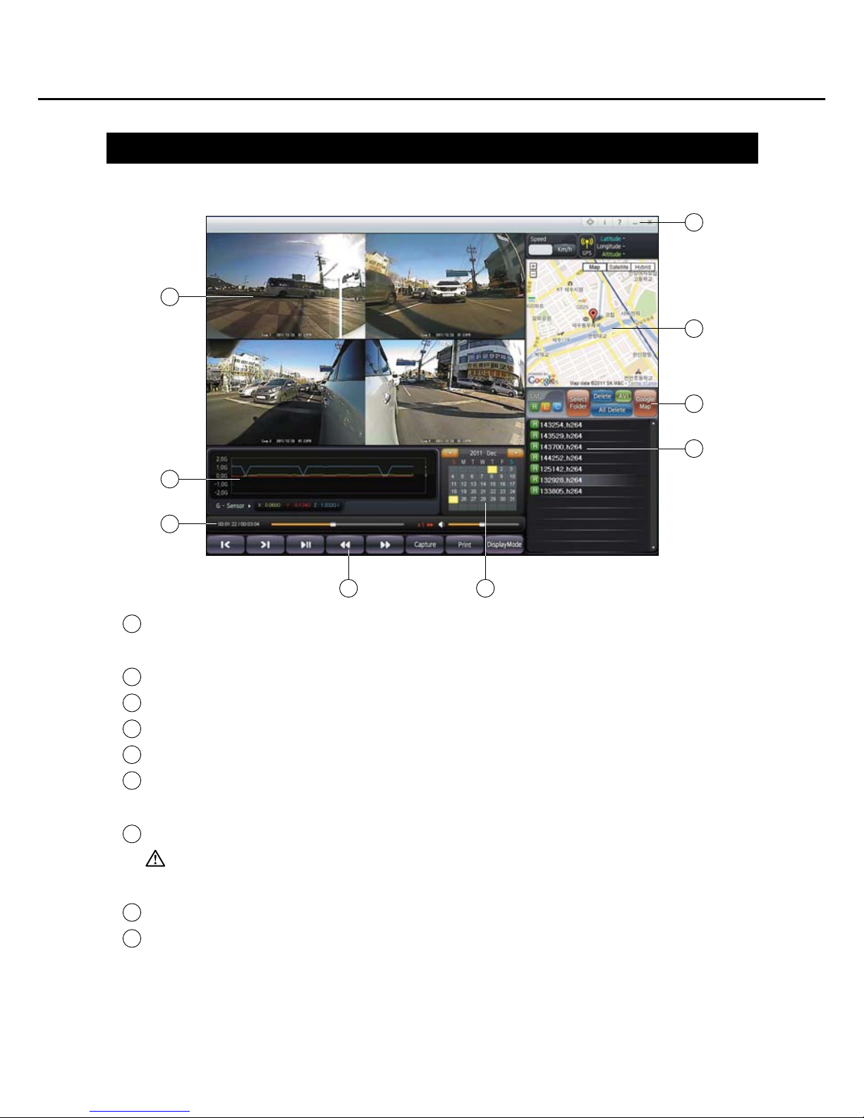
Touch the small window at each channel to enlarge it to the fulle screen. One more
touch will return it to the multi screen.
G.sensor level adjusted for the screen will be displayed while replaying.
The recorded time of the current scene and total recording time will be shown.
You can control reply-related buttons of the player.
The calendar shows the saved date of the recorded files.
There are Full Screen View, Version Information, Window Minimizing, and Player
Finish buttons on this board.
Google Map is displayed.
Caution : The map is displayed only if a file in which GPS location information
is saved is being replayed.
There are List REC, Select Folder, Delete, AVI, and Google Map buttons on this board.
If you click the recorded date on the calendar, recorded files are listed.
(You can select multiple dates at once)
#<Min.PC SPEC : OS -> more than XP SP2
CPU -> more rhan 2.5GHz
Memory -> more than 1GB>
How to use PC Player
1
2
3
4
5
6
7
8
9
1
2
3
4 5
6
7
8
9
33
Page 35
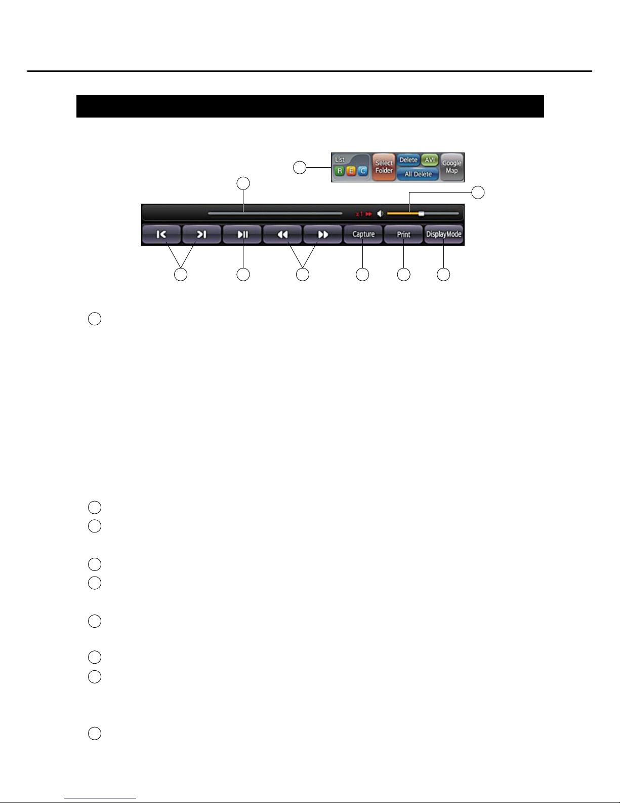
Function Buttons of PC Player
You can control the function buttons.
- R/E/C : (R)View normal recording files, (E)View event recording files,
(C)The button is to see only captured files. If you click all buttons, you can see the
entire files.
- Select Folder : Select a folder in which the recorded file is saved.
- Delete : Select and delete a file on the list.
- ALL Delete : Delete all files saved on the selected date.
(Delete all files saved on the date.)
- AVI : Convert the recorded files into AVI to save in PC.
- Turn on/off Google Map
Select the previous/next file.
The bar is to execute reply. If you click and keep pressing 'execution' button, you can
explorer the files.
The button is to replay/pause.
You can control the replying speed (forwards/backwards) from normal speed to
maximum 16x speed.
The current image is captured and saved as BMP in PC. Pause the scene you want
to capture and designate a folder to save the file.
Print the current image out.
Display Mode button: You can choose version of your PC.
- If you choose lower version, only one channel is displayed on the screen at once.
- If you choose higher version, 4 channels are displayed on the screen at the same time.
The bar is to control volume./ Click the speaker icon to mute it.
How to use PC Player
1
2
3
4
5
6
7
8
9
1
2 54 6 7 8
3
9
34
Page 36
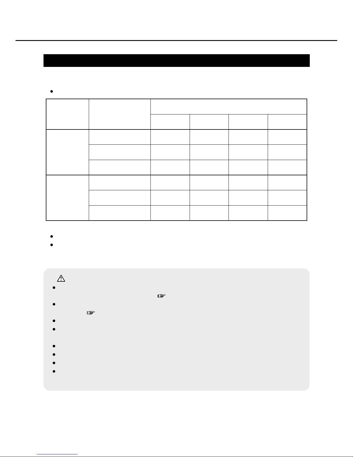
SD Card Recordable Time
How to use PC Player
SD card, max 32GB x 4(pcs), support up to 128GB
The recordable time is estimated at average, so the actual recording time may be
slightly different depending on recording conditions.
Recordable time by SD card memory
Caution:
If the memory is full, recording will be stopped. Make sure that the old files are
set to be deleted automatically. ( Ref.: Continuous Rec, Page 18.)
Do not forget to set 'Protect' or backup important files to your PC, not to be
deleted. ( Ref.: File Protect, Page 15.)
For reliable operation of the device, you should format the SD card regularly.
If you save other articles and/or data in the SD card, it may cause errors or
damages of the device. Do not save other articles and/or data in the card.
Do not pull out the SD card during playing or recording process.
Use proper type SD card: it should be higher than Class 10 level SD card.
Recommended brands of SD card: Sandisk, Transcend or Samsung.
Please check the mark as 'Class10 & Full-HD' on the package before you
purchase SD card.
High(D1)
Normal(Half D1)
Low(CIF)
High(D1)
Normal(Half D1)
Low(CIF)
32 Gbyte
9h 15m
18h 30m
37h
9h 10m
18h 20m
36h 40m
64 Gbyte
18h 30m
37h
74h
18h 20m
36h 40m
73h 20m
Video
Format
Recording Time(hour, minute)
NTSC
(4 Channel)
PAL
(4 Channel)
Video
Quality
96 Gbyte
27h 45m
55h 30m
111h
27h 30m
55h
110h
128 Gbyte
37h
74h
148h
36h 40m
73h 20m
146h 40m
35
Page 37

1. H/W
- Storage : SD Card 32GByte X 4 Slot / Total 128GByte
- LCD : Built in 8" TFT LCD (WVGA 800x480, with Touch Panel)
- Camera : 4Ch + 1Ch (Option) input (1 Vp-p, 75Ω) /NTSC, PAL
- Video Output : CVBS 1 Ch. (1 Vp-p, 75Ω) /NTSC, PAL
- Audio In 4Ch (Camera Mic. input 4Ch, Mono, Record)
- Audio Output 1Ch (RCA) & Built in Speaker(1.2Watt, Mono)
- Keys : 6 function
- Trigger 4 input (Cable Input : 12 ~ 24V)
- ALS Sensor 1EA (Night & Daytime Brightness detection)
- Emergency Back Up : Internal Battery (2650mA/h)
- GPS : External Module Antenna (Data storage, Google map link)
- G. sensor installed inside (Data storage, Rec. link)
- Power : DC 12V~36V (DC12V 1.5A)
2. S/W
- Operating system : Embeded Linux
- Recording File
Video Quality : High / Normal / Low
Resolution : D1 / Half D1 / CIF
Bitrate : 2Mbps / 1Mbps / 512Kbps
Framerate : Rec. frame per sec. (Select 4step)
- Recording Performance
4Ch Full D1 Rec. & 4Ch Mic. Rec.
120fps D1 encoding + 120fps D1 decoding@NTSC
100fps D1 encoding + 100fps D1 decoding@PAL
- Video/Audio Codec
Video : H.264 Main Profile@ Level 4.0 (or lower)
Audio : AMR Codec
- Image player support (Capture Image Viewer)
BMP, Jpeg, MAX. Size : 1280 x 1024
- Support Digital watermark
- Multi Language
- PC Player : Support (O/S Windows)
3. Size
- Dimensions : 218mm(W) x 150mm(H) x 50mm(D)
- Weight : approx. 2.8kg
Specification
36
Page 38

 Loading...