

Page 1
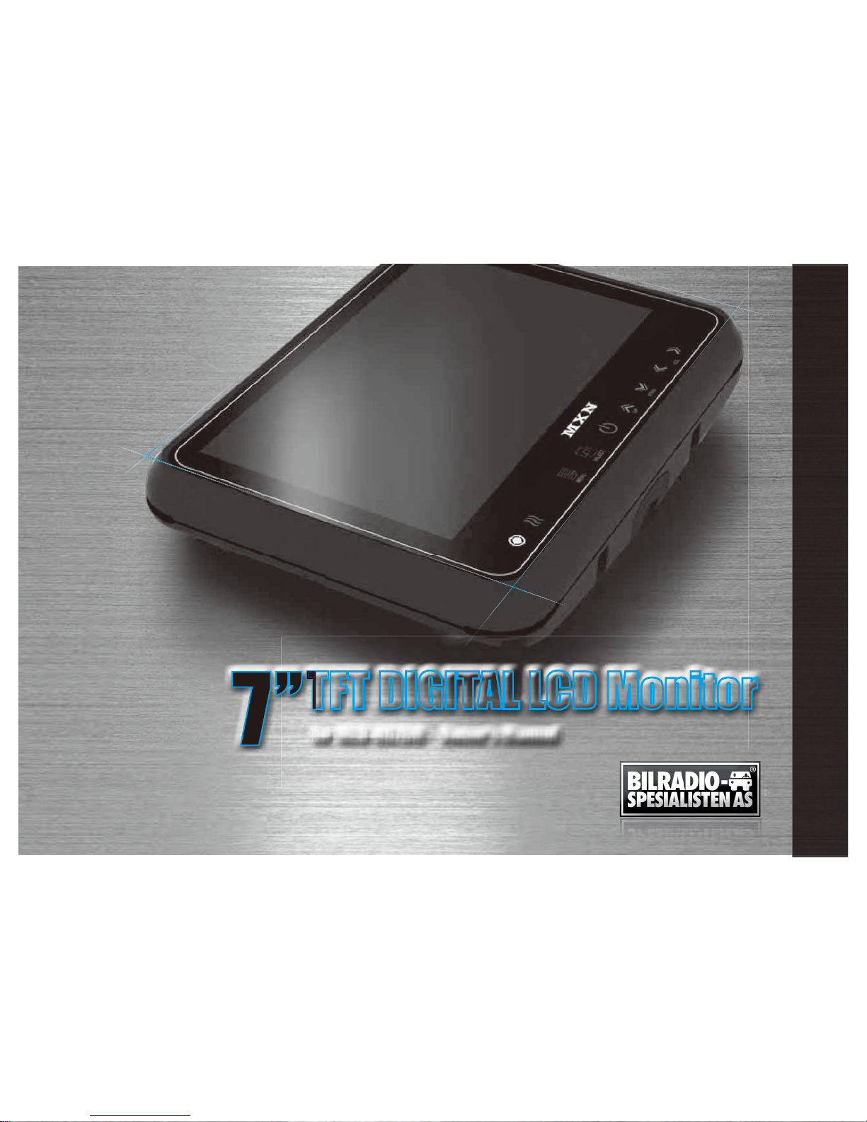
TFT DIGITAL LCD Monitor
for MXN-HD7DM - Owner’s Manual
f
Page 2
·I·
N·D·E·X
·
Package Contents
Connection
Operation
System Setting
Function
Picture
Camera Set up
Normal/Mirror
Auto Picture Scan
Camera Trigger
Distance Marker Adjust
Scan ON/OFF Function
Lock ON/OFF Function
Installation
Monitor installation with Stand bracket & Sunvisor
Installation of heavy duty mounting brackets
Specication
03
11
04
05
05
06
06
07
07
08
09
10
10
12
12
13
14
Page 3
3
Owner’s Manual
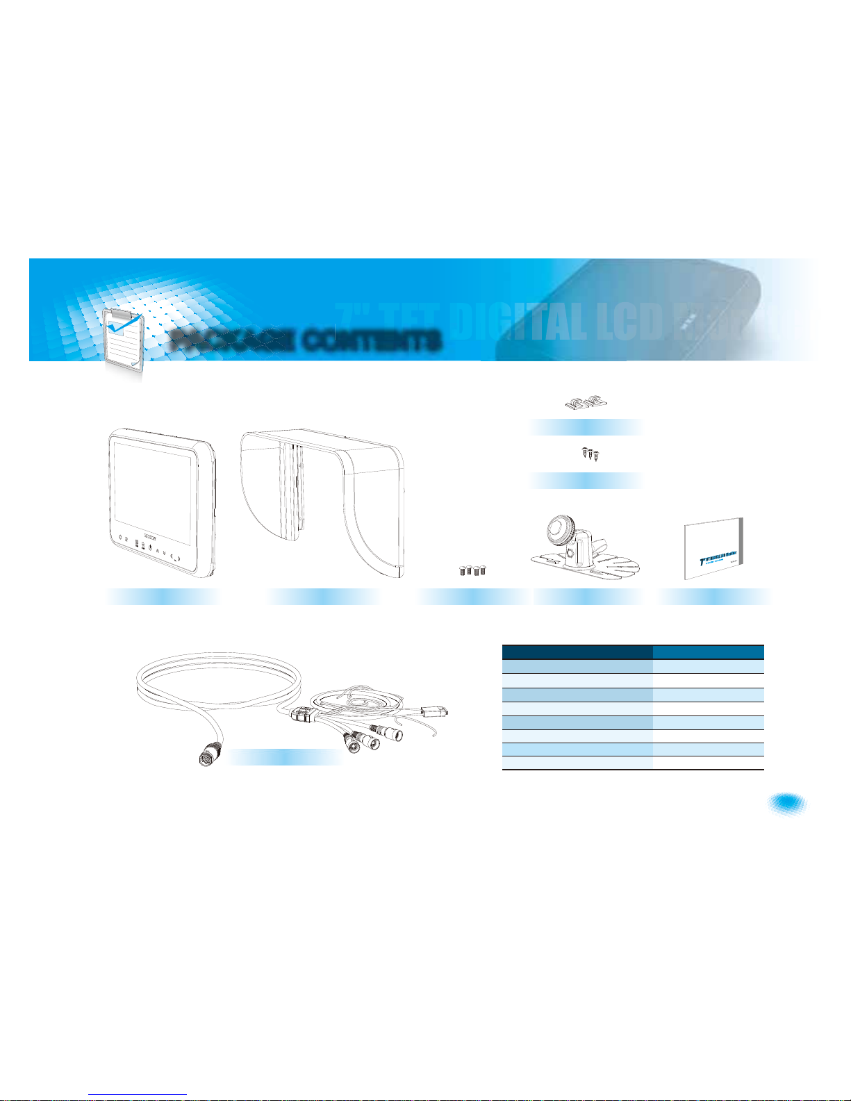
PACKAGE CONTENTS
MONITOR SUNVISOR STAND BRACKET MANUAL
BRACKET SCREWS
SUNVISOR SCREWS
CABLE CLIP
ITEM Q’TY
MONITOR 1
SUNVISOR 1
SUNVISOR SCREW 4
STAND BRACKET 1
BRACKET SCREW 3
CABLE CLIP 2
CAMERA INPUT CABLE 1
MANUAL 1
CAMERA INPUT CABLE
Page 4
4
7" TFT DIGITAL LCD Moniter
OPERATION
d
b
a
c
f
e
g
h
i
j
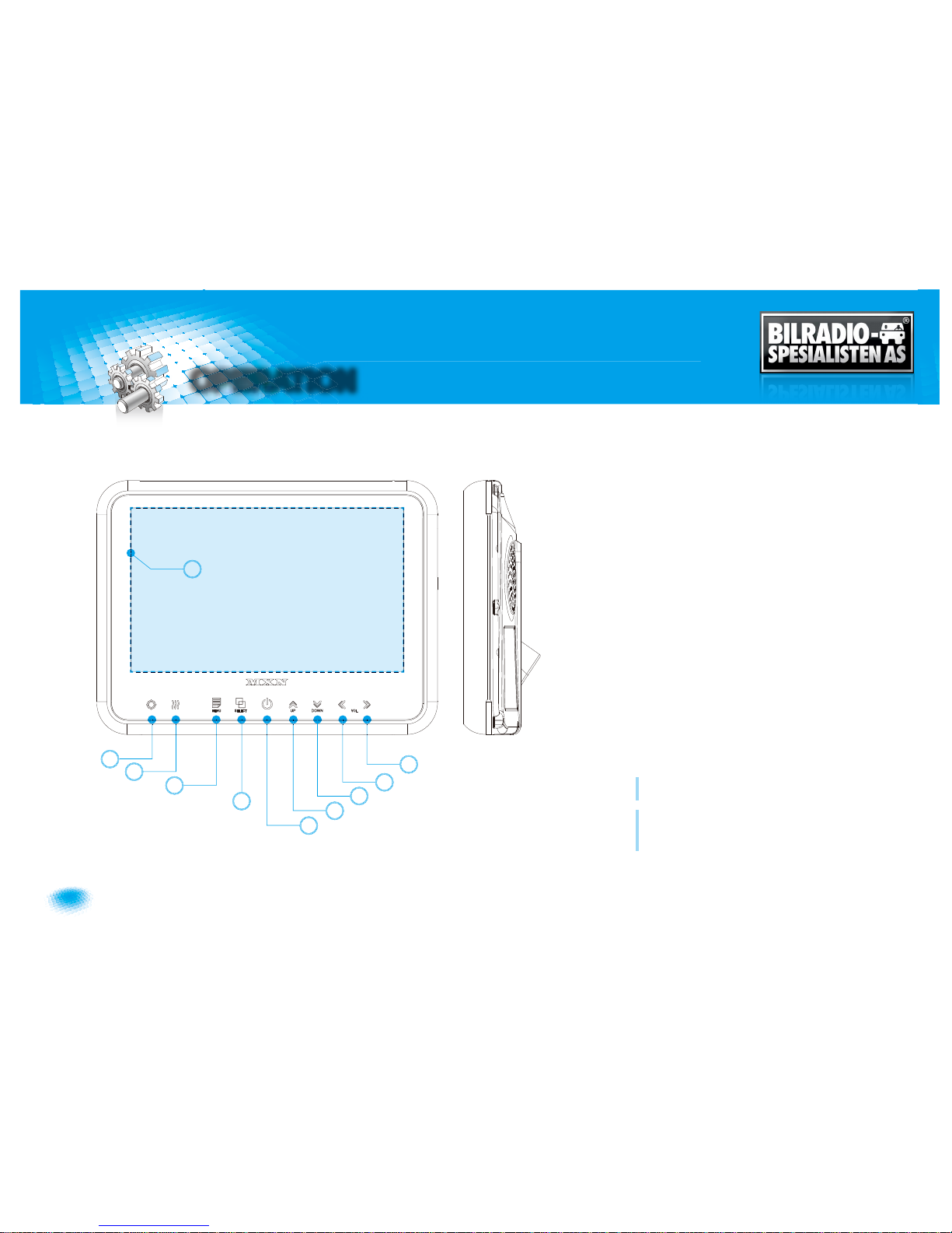
A . DAY/NIGHT SENSOR (CDS)
Automatic brightness control sensor.
B . HEATER LAMP
Orange color will be illuminated in case heater function is
activated.
C . MENU
Press [MENU] button for system setting.
D . SELECT
Press [SELECT] button to select the respective camera channel.
(CAM1-CAM2-CAM3-CAM1..)
E . POWER
Press [POWER] button to turn on/off the monitor.
F . UP
G . DOWN
H . LEFT
I . RIGHT
J . VIEW AREA
Press [UP/DOWN] button to navigate the menu for
system setting.
Press [LEFT/RIGHT] button to adjust monitor volume.
Use [LEFT/RIGHT] button to change OSD setting
during system setting.
Page 5
5
Owner’s Manual
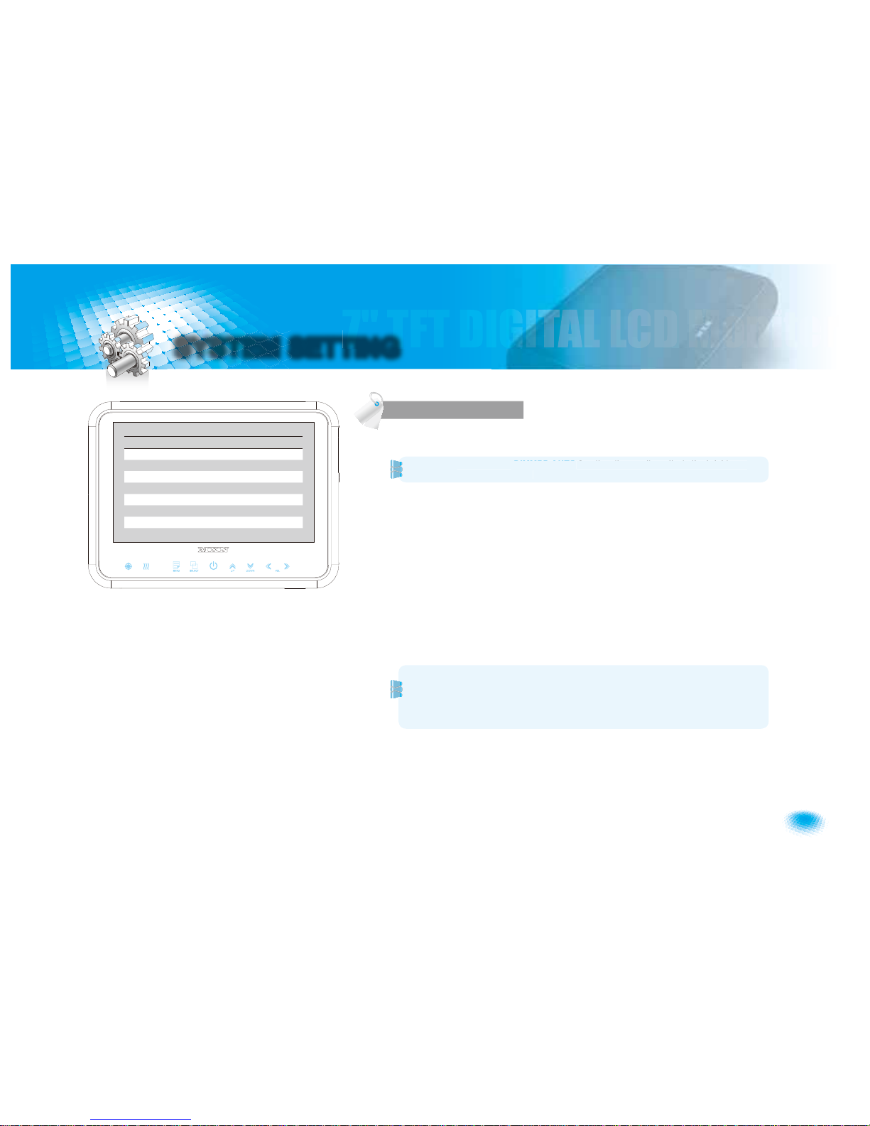
SYSTEM SETTING
DIMMER (Automatic Brightness Control)
Select AUTO or OFF to have Automatic or Manual brightness of the monitor.
REMARK: By activating DIMMER AUTO function, the monitor adjusts the brightness
according to the environment.
LANGUAGE
Provide 6 Multi-lingual OSD [ENGLISH, SWEDISH, DANISH, NORWEGIAN, DUTCH,
FINNISH].
Select the preferred LANGUAGE.
AUTO POWER
Select monitor activation function as below.
[AUTO] Monitor keeps the last setting in memory.
[ON] Monitor starts up
௲
Power-ON௳mode automatically.
[OFF] Monitor starts up
௲
Stand-By௳mode automatically.
MONITOR HEATER
Select MONITOR HEATER௲ON௳to have automatic heating function in order to enable
fast picture start during extreme cold weather condition.
RESET
Press >> button to go the factory default setting.
SYSTEM INFO.
Refers to system information of the monitor.
FUNCTION
: By activatin
g
D
IMMER AUTOfunction, the monitor adjusts the brightness
a
ccording to the environment.
FUNCTION
DIMMER AUTO/OFF
LANGUAGE ENGLISH/…
AUTO POWER AUTO/ON/OFF
MONITOR HEATER ON/OFF
RESET >
SYSTEM INFO. VER 1.0
Remark: During MONITOR HEATER ON mode,
Heating activates automatically when the temperature of inside monitor is below 0
degree Celcius.
When the temperature of inside monitor is over 0 degree Celcius, heating stops
automatically.
Page 6
6
7" TFT DIGITAL LCD Moniter
SYSTEM SETTING
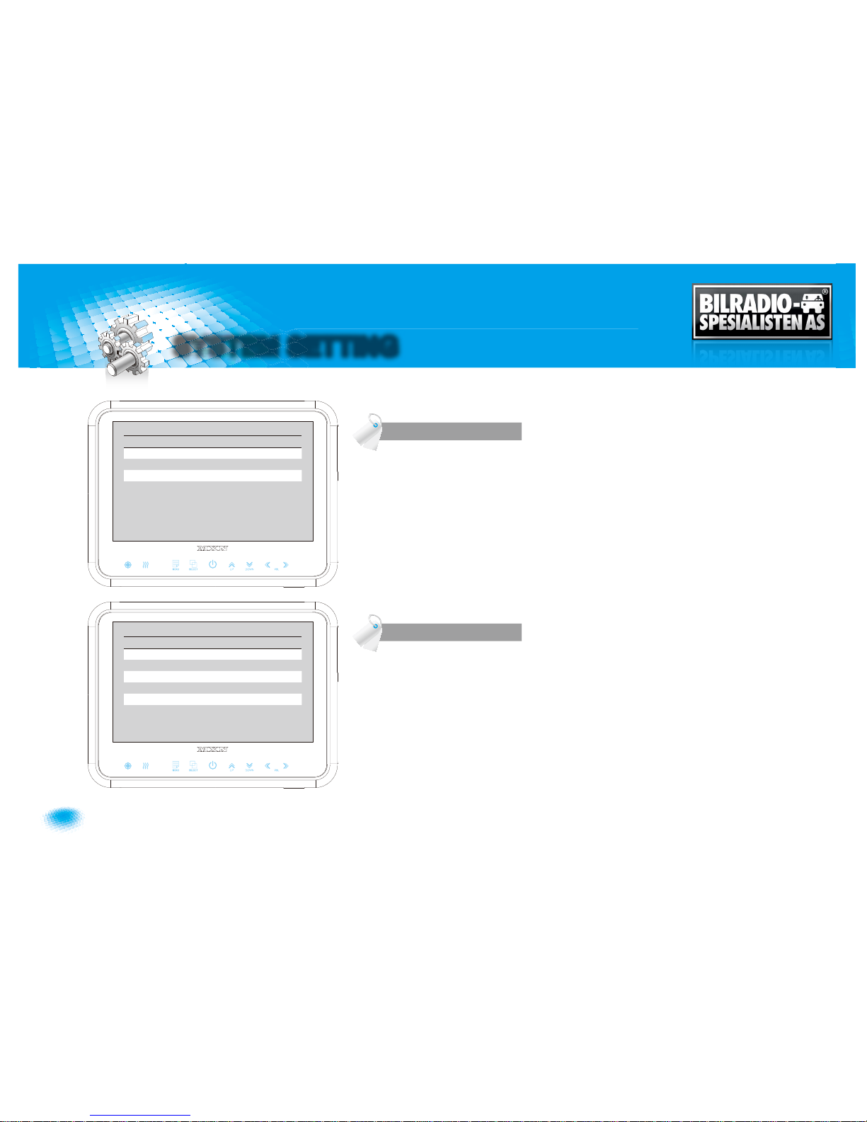
Press [
LEFT/RIGHT
] button to adjust preferred
PICTURE
of the monitor.
TRIG. DELAY
When a
TRIGGER
wire is connected to a pulse DC power signal (e.g. direction
indicator lights) then the [
TRIGGER DELAY
] function avoids repeating
ON/OFF
of the
monitor.
CAMERA NAME
CAMERA NAME
can be selected as
CAM1, 2, 3/REAR/LEFT/RIGHT/FRONT
.
PICTURE
CAMERA SET UP
PICTURE
CONTRAST 50 (0-100)
BRIGHTNESS 50 (0-100)
COLOR 50 (0-100)
TINT 50 (0-100)
CAMERA SET UP
CAM1 TRIG. DELAY
2 SEC (0-9)
CAM2 TRIG. DELAY
2 SEC (0-9)
CAM3 TRIG. DELAY
2 SEC (0-9)
CAM1 NAME
CAM1/REAR/LEFT/RIGHT/FRONT
CAM2 NAME
CAM2/REAR/LEFT/RIGHT/FRONT
CAM3 NAME
CAM3/REAR/LEFT/RIGHT/FRONT
Page 7
7
Owner’s Manual
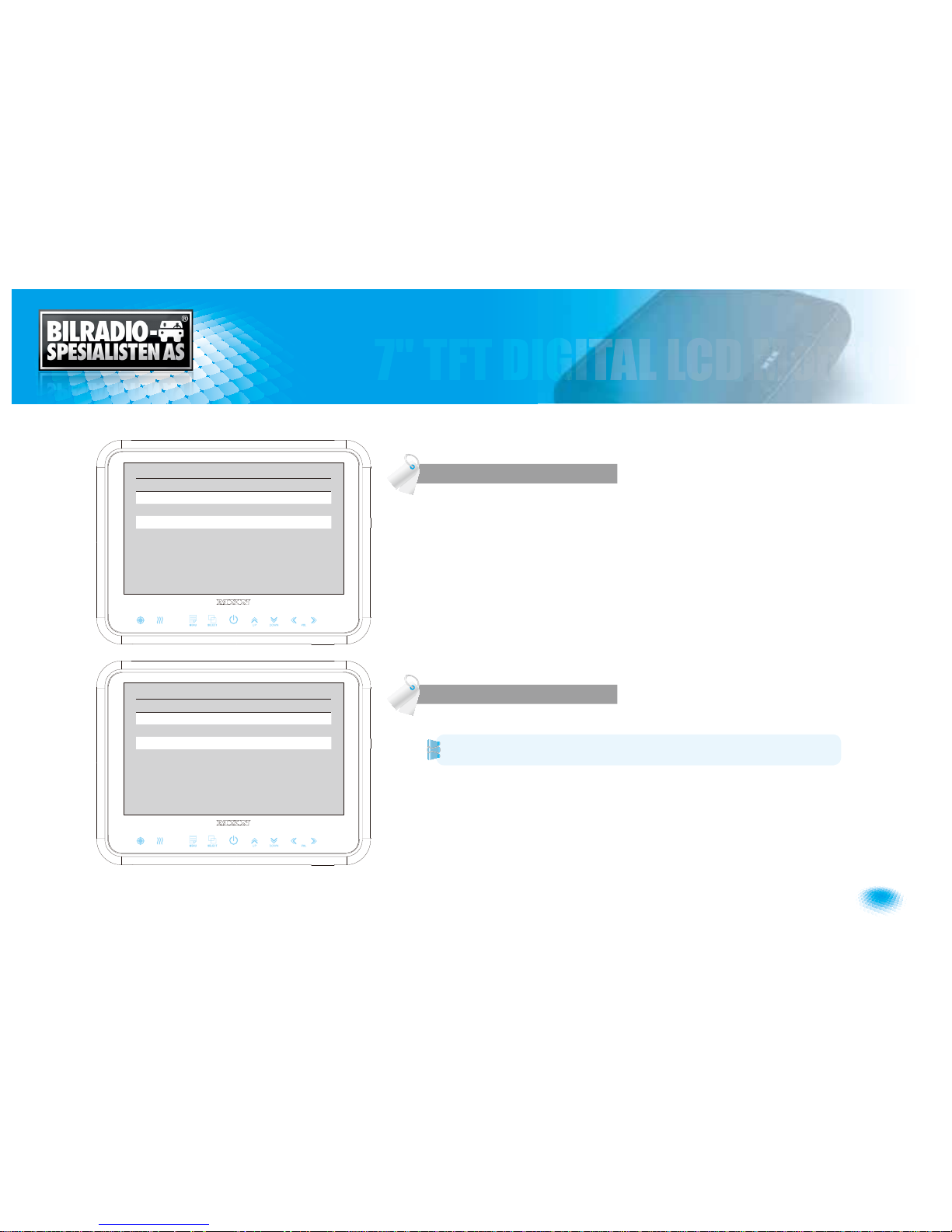
NORMAL/MIRROR
Each camera picture (CAM1/CAM2/CAM3) can be switchable as
NORMAL/MIRROR
image.
UP/DOWN
Camera pictures can be switchable as
UP/DOWN
image.
Each scanning time of CAM1/CAM2/CAM3 can be selected.
REMARK: If the SCAN TIME is set as௲0௳, monitor skips its channel during the
scanning.
Press [UP] button for 4 seconds to
ACTIVATE/INACTIVATE
auto scanning function.
NORMAL/MIRROR
AUT O PICTURE SCAN
NORMAL/MIRROR
CAM1 NORMAL/MIRROR
CAM2 NORMAL/MIRROR
CAM3 NORMAL/MIRROR
UP/UPSIDE DOWN UP/UPSIDE DOWN
AUTO PICTURE SCAN
AUTO SCAN ON/OFF
CAM1 SCAN TIME 2 SEC (0~9)
CAM2 SCAN TIME 2 SEC (0~9)
CAM3 SCAN TIME 2 SEC (0~9)
Page 8
8
7" TFT DIGITAL LCD Moniter
SYSTEM SETTING
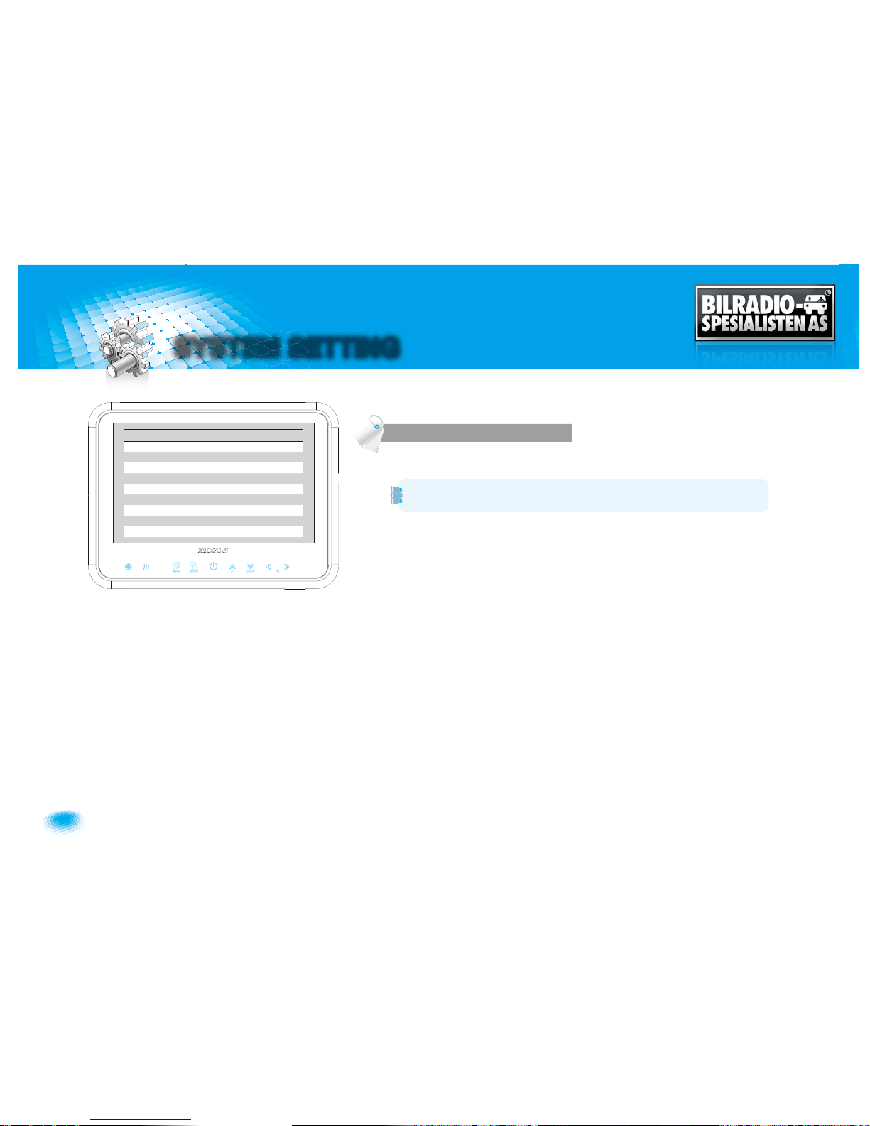
TRIGGER 1/2/3 (Trigger source selection)
Select the required trigger source at CAM1/CAM2/CAM3.
REMARK
TRIGGER PRIORITY: TRIGGER 1 > TRIGGER 2 > TRIGGER 3
CAM1 DIST. MARKER
SelectON to have distance marker (parking line) for
CAM1
.
Distance marker is displayed as soon as
TRIGGER 1
signal is activated.
SPEED SWITCH
The orange wire needs to be connected with the vehicle’s tacho signal and via
MENU
the
SPEED SWITCH
needs to be selected ON.
At
FREQUENCY
67Hz setting(and most common used tacho signal) the selected
camera will be displayed during a speed of 0~33km/h. Select the concerning camera
via௲
UNDER FREQUENCY CH
:௳(At different type tacho signals the
FREQUENCY
needs
to be adjusted into higher or lower value than this example)
Over 33km/h (72Hz) the selected camera will be switched
OFF
automatically. When
the speed slows down, then the selected camera will be switched ON automatically
again at 30km/h. Instead of automatic switch
OFF
at a speed over 33km/h it is also
possible to activate another video source, such as a navigation picture from an optional
navigation computer. In this case user needs to select௲
OVER FREQUENCY DISPLAY
:
ON
௳and user needs to select௲
OVER FREQUENCY CH
:௳
In case of
TRIGGER
activation during௲
SPEED SWITCH ON
௳mode, then
TRIGGERS
1~ 3 will overrule௲
SPEED SWITCH
௳function.
CAMERA TRIGGER
TRIGGER PRIORITY: TRIGGER 1 > TRIGGER 2 > TRIGGER
3
CAMERA TRIGGER
TRIGGER 1 CAM1/CAM2/CAM3
TRIGGER 2 CAM2/CAM3/CAM1
TRIGGER 3 CAM3/CAM1/CAM2
CAM1 DIST. MARKER MARKER ON/OFF
SPEED SWITCH ON/OFF
FREQUENCY 67 Hz
UNDER FREQ. CAM CAM3/CAM1/CAM2
OVER FREQUENCY DISPLAY ON/OFF
OVER FREQ. CAM CAM1/CAM2/CAM3
Page 9
9
Owner’s Manual
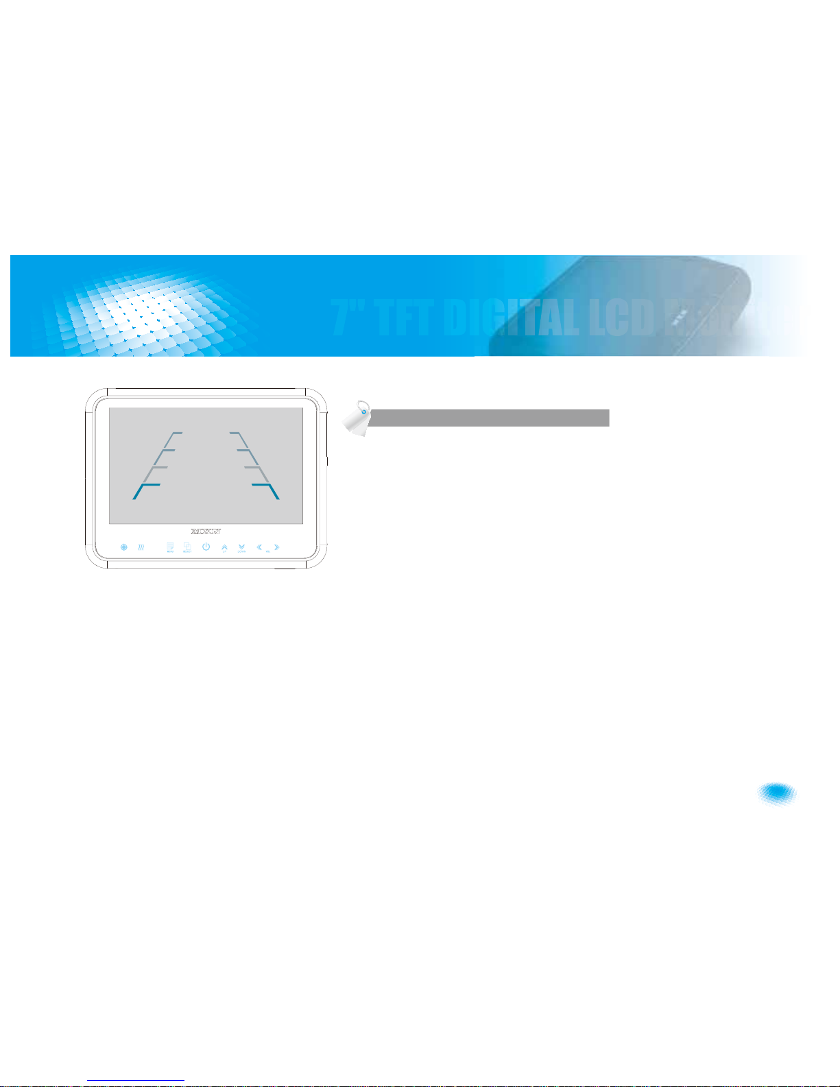
User can adjust location of distance marker.
At Power ON mode, select distance marker by pressing [
UP/DOWN
] buttons.
When color of distance markers is seen as
RED
color, user can adjust the lines
UP/
DOWN
or
LEFT/RIGHT
.
When both color of distance markers are seen as
RED
color, both lines can be
adjusted
LEFT/RIGHT
.
When left color of distance marker is seen as
RED
color, left line of distance marker
can be adjusted
LEFT/RIGHT
.
When right color of distance marker is seen as
RED
color, right line of distance marker
can be adjusted
LEFT/RIGHT
.
DIST ANCE MARKER ADJUST
Page 10
10
7" TFT DIGITAL LCD Moniter
SYSTEM SETTING
At
Power-ON
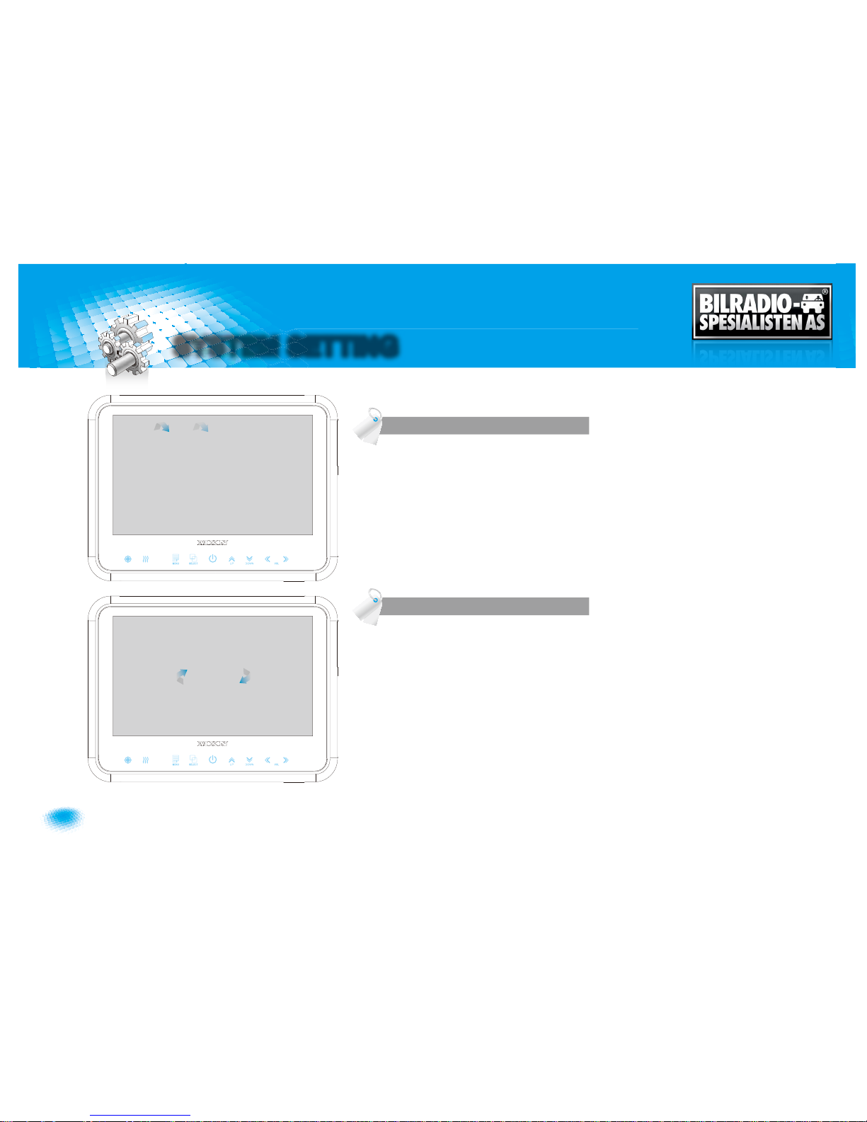
mode, hold [UP] buttons pressed for 4 seconds to activate Auto Scan
Picture function.
During the auto scanning mode, press [UP] button for 4 seconds to inactivate Auto
Scan Picture function.
LOCK ON/OFF FUNCTION
The set up menu can be locked as prevention against unauthorized users.
LOCK ON mode
At
Power-ON
mode, hold [
DOWN
] button pressed for 3 seconds to set up
LOCK ON
function.
When [
LOCKED
] is displayed on the screen, user can use [
POWER, SELECT, VOLUME
]
buttons only and use can do setting for
PICTURE
menu.
LOCK OFF mode
At
Power-ON
mode, hold [
DOWN
] button pressed for 3 seconds to set up
LOCK OFF
function.
When [
UNLOCKED
] is displayed on the screen, user can use all functions of the set up
menu.
SCAN ON/OFF FUNCTION
LOCK ON/OFF FUNCTION
CAM1
SCAN
CAM2
S
CAN
CAM3
SCAN
LOCKED
UNLOCKED
Page 11
11
Owner’s Manual
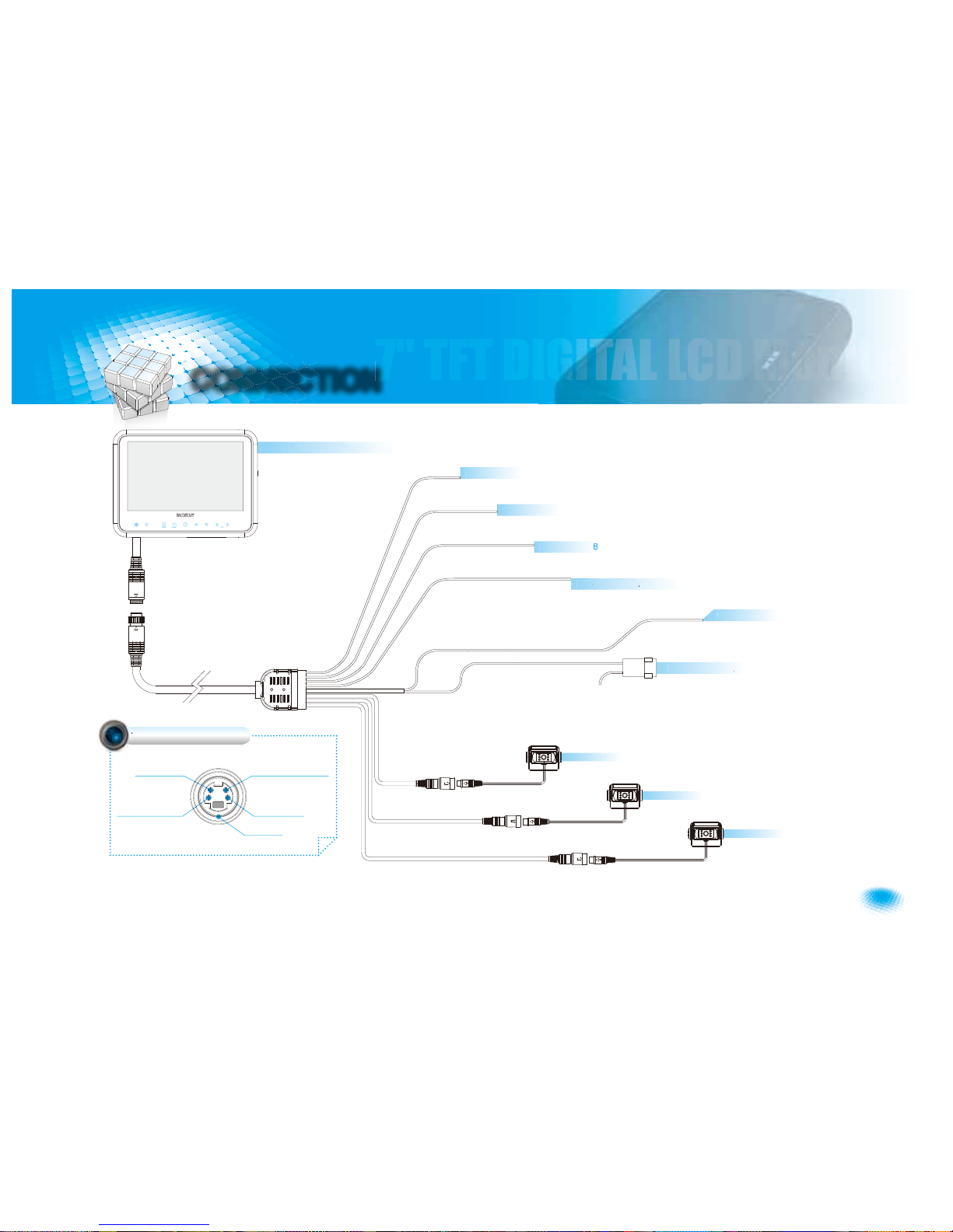
CONNECTION
Camera 1(Option)
Camera 2(Option)
Camera 3(Option)
N
AL)-
S
e
dSwitch
h
(TA
H
IG
N
rang
e
G
3-lue
2-
hit
e
reen
7” TFT DIGITAL LCD Monitor
4V DC via ignition(+15)-
po
er12
/
2
n
d-
l
ack
AUDIO INPUT
+12V DC OUTPUT,
HEATER & SHUTTER
+12V DC OUTPUT,
POWER
VIDEO INPUT
GROUND
CAMERA INPUT
Page 12
12
7" TFT DIGITAL LCD Moniter
INSTALLATION
A
B C
D
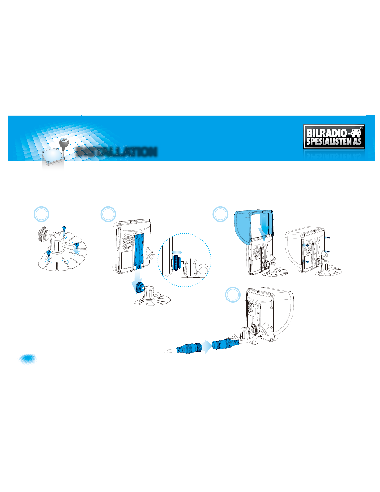
MONITOR installation with STAND BRACKET & SUNVISOR
Remove a protection tape and attach STAND BRACKET into stand place, then fix it with the supplied screws.
Connect STAND BRACKET with monitor and adjust height/angle.
Attach SUNVISOR to the MONITOR and fix it with the supplied screws.
Connect CAMERA INPUT CABLE to the MONITOR.
A
B
C
D
Page 13
13
Owner’s Manual
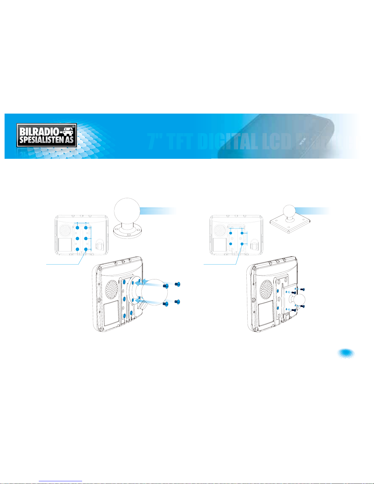
TYPE A(option) TYPE B(option)
Installation of heavy duty mounting brackets
MONITOR can be connected with different type of heavy duty mounting brackets.
Please check the compatibility in advance, then please follow installation as described below.
FMBK 5Ý10mm FMs 3.5Ý10mm
38mm
40mm
30mm
38mm
38mm
YWXYTWXTZXGGG㝘䟸G[aX^aY^
Page 14
14
7" TFT DIGITAL LCD Moniter
SPECIFICATION
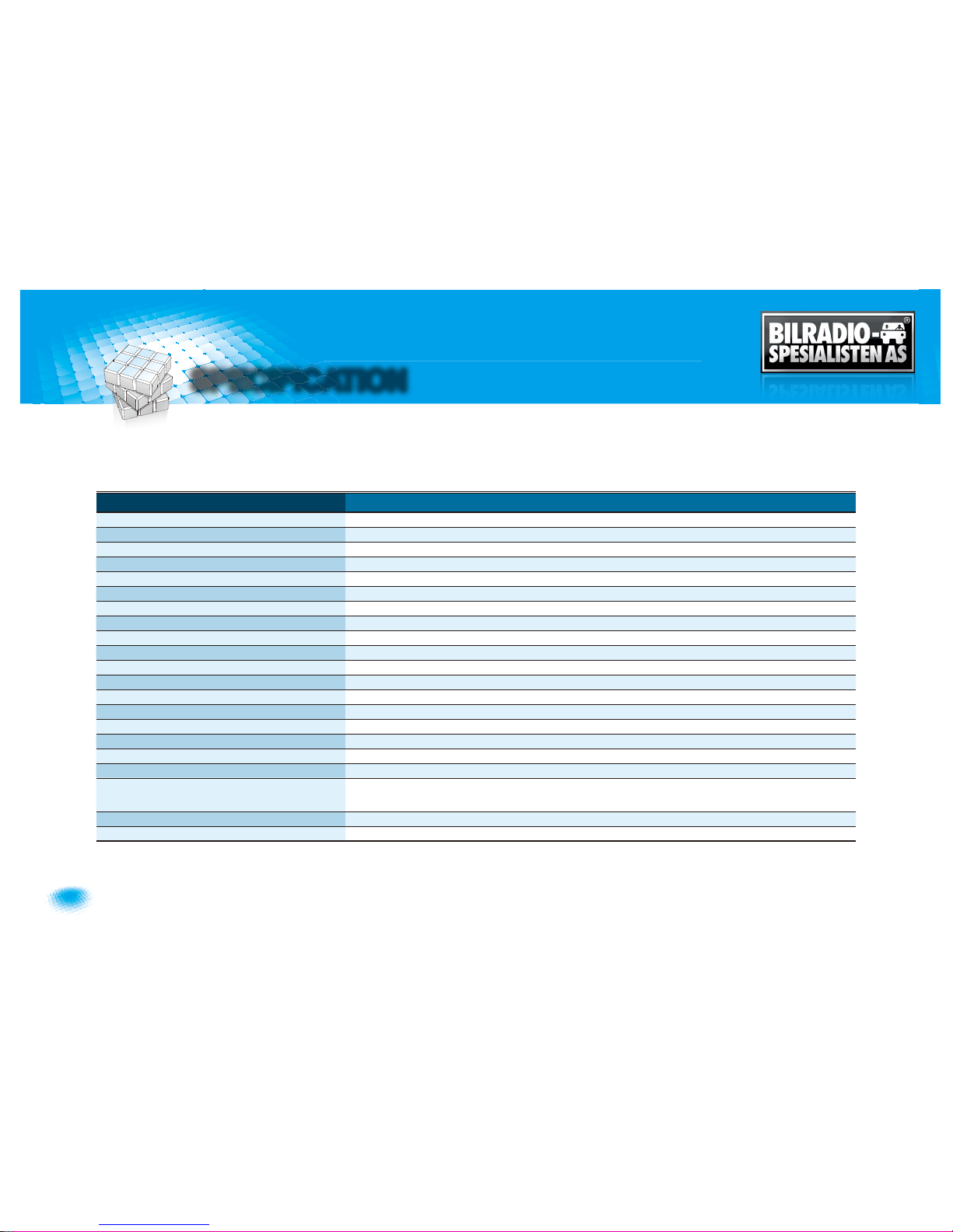
ITEM SPECIFICATION
LCD Screen Size 7” Wide Diagonal
Dimensions 190(W)GÝ 142(H)Ý 42.85(D)mm
Display dimensions 152.4GÝ 91.44mm
Power Input DC 12 to 30 Volt Free Input
Power Consumption 12 Watt Max.
Video System NTSC / PAL / SECAM Auto Detection
Sync. System Internal
Brightness 500 cd/m
2
Display Resolution 800Ý 480 pixel
Viewing Angle Top: 50. Bottom: 60. Left: 65. Right: 65.
Color Configuration RGB Stripe
Dimmer Automatic / Manual
Speaker Impedance 8 ohm, 0.3 Watt Max.
Operating Temp. -25°C ~ +75°C
Storage Temp. -30˚C to + 85˚C
Impact Rating 4G
Camera Connector 4-pin mini DIN (MXN configuration)
Housing Soft black(Al12)
ON-Screen Display
Control Functions
Volume · Brightness · Color · Contrast · Tint · CAM Screen 1/2/3 · CAM Trigger 1/2/3 · Heater ·
Speedswitch · Auto Power · Distance marker · Auto Picture Scan · Dimmer · Language · Direction · Reset.
Supplied Accessory Die-Cast Mounting Bracket / 1 pce, Screw Kit / 1set, Manual, Sun Shield / 1 pce, Power cable / 1 set
Weight 790g
Page 15
TFT DIGITAL LCD Monitor
for MXN-HD7DM - Owner’s Manualf
o
 Loading...