

Page 1
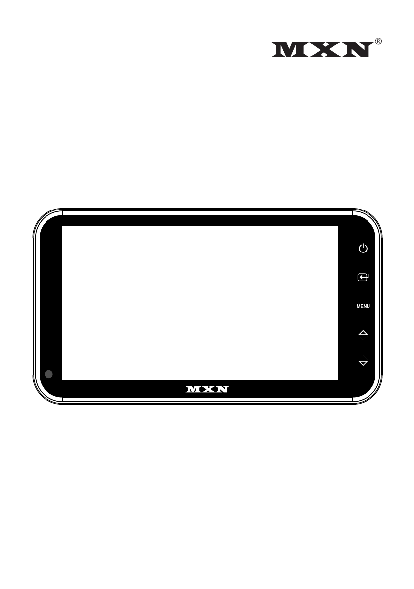
OWNER’S MANUAL
7” Digital LCD monitor
for allround vision
MXN-7DM
Model : MXN-7DM
Design and Specifications are subject to change without notice.
Page 2

MXN-7DM
Model : MXN-7DM
INDEX
Safety Instructions
Package Contents
Operation
System Setting
Camera setting
Trigger setting
Auto Scan setting
Day/Night setting
Advanced menu
Installation
Connection
Specifications
.......... 03
.......... 04
.......... 05
.... 07~12
.......... 07
.......... 08
.......... 10
.......... 10
.......... 11
.......... 13
.......... 14
.......... 15
Page 3
Safety Instructions
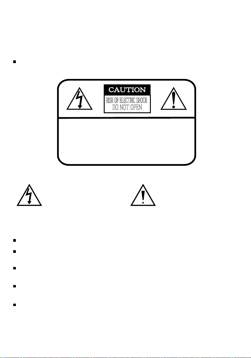
WARNING
To avoid electric shock, do not open the cabinet. Refer servicing to qualified personnel only.
CAUTION
RISK OF ELECTRIC SHOCK
DO NOT OPEN
CAUTION: TO REDUCE THE RISK OF ELECTRIC SHOCK,
DO NOT REMOVE COVER (OR BACK).
NO USER-SERVICEABLE PARTS INSIDE.
REFER SERVICING TO QUALIFIED SERVICE PERSONNEL.
This symbol is intended to alert
the user to the presence of
uninsulated "dangerous voltage"
within the product's enclosure
that may be of sufficient magnitude to constitute risk of electric
shock to persons.
Use only DC 12V~DC 30V.
In case that dust or liquid was soaked into the housing, please turn off power and consult an
experienced technician before using.
Do not install the unit in an extremely hot or humid place(radiator, air duct, etc.) or in a place
subject to direct sunlight, excessive dust, mechanical vibration or shock
If your vehicle has been parked in direct sun light resulting in a considerable rise in temperature
inside the vehicle, allow the unit to cool off before operating
Clean the unit with a slightly damp soft cloth
Use a mild household cleaner
Never use strong solvents such as thinner or benzine as they might damage the
finish of the unit.
This symbol is intended to alert
the user to the presence of important operating and maintenance (servicing)
instructions in the literature
accompanying the appliance.
- 3 -
Page 4
Package Contents
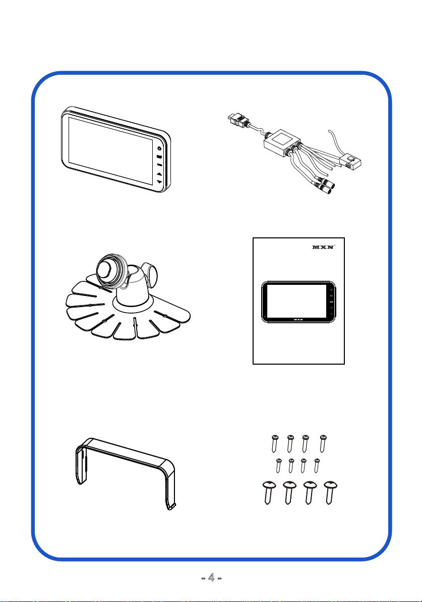
MONITOR CAMERA INPUT CABLE
OWNER’S MANUAL
7” Digital LCD monitor
for allround vision
MXN-7DM
Model : MXN-7DM
Design and Specifications are subject to chage without notice.
(RAIL TYPE)
FIXING BRACKET USERS MANUAL
SUNVISOR SCREW KIT
- 4 -
Page 5
Operation
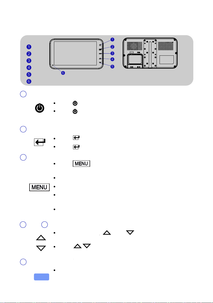
POWER
SELECT
MENU
UP
DOWN
DAY/NIGHT SENSOR
POWER1
Touch icon to turn the monitor on.
Touch icon to turn the monitor off.
* NOTE - Monitor start mode will follow “AUTO POWER ” setting.
SELECT2
Touch icon to select CAMERA.
Touch icon to select the option in SET UP MENU.
MENU3
Touch icon to enter Display Menu(Short key) and
Main Menu(Long key).
Touch once to enter menu mode.
UP DOWN4 5
DAY/NIGHT SENSOR (Photo T.R)6
Touch again to exit from menu mode.
Selectable OSD Menu Disappears within 10 sec if there`s
no new button (icon) pressed.
Touch menu button over 2 sec to go back to main menu
from display menu.
While in Menu mode and navigate through the available
menu options.
Touch to adjust Bright, Contrast, Color, Sharpness,
Tint Volume and other setting values.
Automatic Brightness Control
The brightness of the monitor is adjusted automatically
by the Photo T.R accordingly to the circumstance.
- 5 -
Page 6
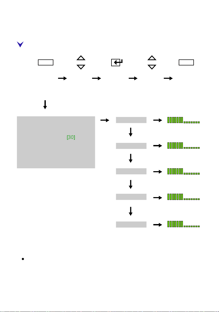
DISPLAY MENU
MENU MENU
MENU UP/DN SELECT UP/DN MENU
Short Key
(more than Touch 1 sec)
-DISPLAY MENU-
Operation
BRIGHT
1. BRIGHT
2. CONTRAST
3. COLOR
4. SHARPNESS [30]
5. TINT
Shortkey Menu can control Bright, Contrast, Color and Sharpness, Tint for
individual channel ( CAM1, CAM2 )
How to adjust : Select camera ( CAM1, CAM2 ) and press the “Menu” icon with short
time.
Now you can adjust.
[30]
[30]
[30]
CONTRAST
COLOR
SHARPNESS
NTSC MODE
TINT
* "TINT" menu is displayed in NTSC only.
- 6 -
Page 7
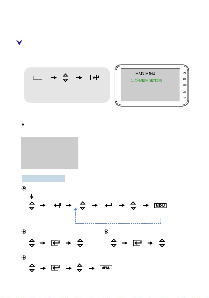
System Setting
SETUP MENU
Touch MENU icon for a while (over 2 sec) to enter MAIN MENU.
Selectable OSD MENU disappears within 10 sec if there is no new icon touched.
MENU
MENU UP/DN SELECT
long key
(more than 2 sec)
up / down shifting
option setting
-MAIN MENU-
1. CAMERA SETTING
2. TRIGGER SETTING
3. AUTO SCAN SETTING
4. DAY/NIGHT SETTING
5. ADVANCED MENU
1. CAMERA SETTING
Camera setting menu can control “MIR/NOR”, “UP/DOWN”, “CAMERA NAME,” “SORT”
for individual camera (CA1,CA2)
1. CAMERA SETTING
CAM1
NOR/MIR [MIRROR ]
UP/DOWN [UP ]
CAMERA NAME: CAM1
SORT: [SHUTTER ]
SUBDIVISION MENU
NOR/MIR
shifting option setting shifting option setting shifting exit
UP/DOWN: [UP, DOWN]
CAMERA NAME: [CAM1or2, FRONT, REAR, LEFT, RIGHT, SIDE, CENTER, ROOM]
SORT: [NORMAL, SHUTTER]
- 7 -
Page 8
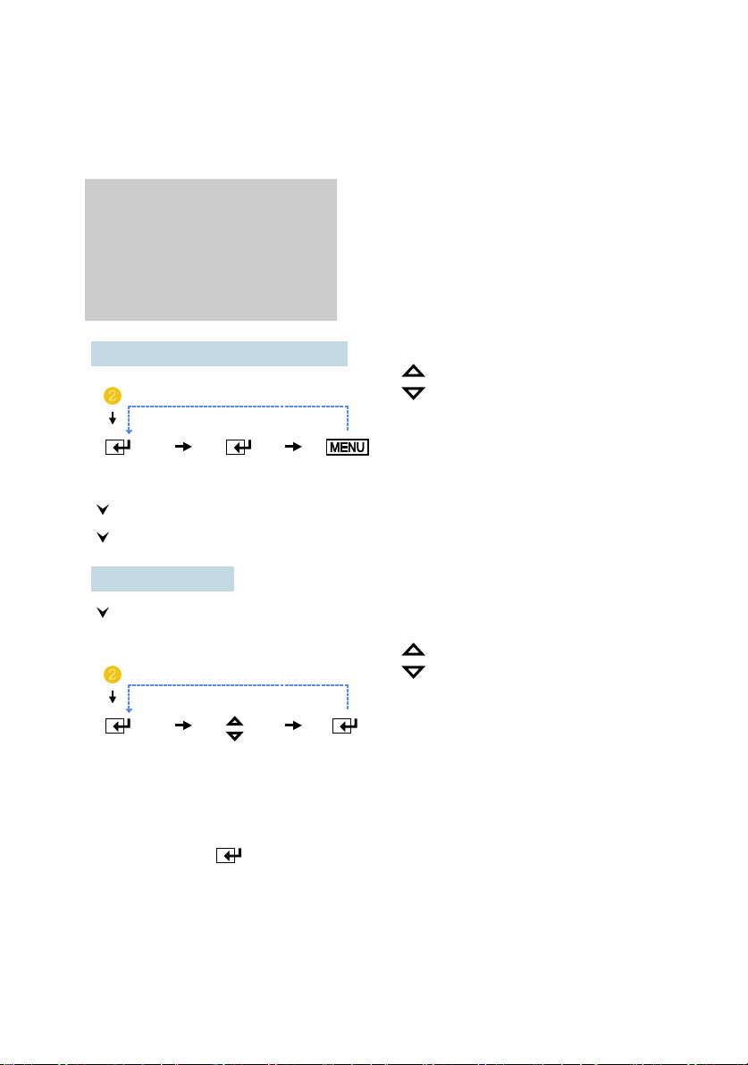
System Setting
2. TRIGGER SETTING
2. TRIGGER SETTING
TRIGGER1
SOURCE
MARKER [A;B;OFF]
MARKER SETTING
SOURCE: [CAM1 => CAM2 => SKIP]
[CAM 1 ]
[02sec
]DELAY
2
selecting option setting exit
User can use 2 triggers and each trigger source (CAM1,2) can be selected.
When the trigger is activated, the selected source's image is displayed.
DELAY:[0~20SEC]
Each trigger's delay time is adjustable from 0 sec to 20 sec.
2
DELAY UP/DOWN SOURCE
selecting shifting option srtting
* NOTE
Trigger1,2
UP/DN
Trigger1,2
UP/DN
- Source select, Delay time setting and MARKER ON/OFF are only available
with (SELECT) key.
- If one trigger is actviated by an intermittent signal (e.g. from an indicator
light) the delay must be activated to prevent the picture from flickering.
- Trigger1 has higher priority than Trigger2.
So, in case Trigger1 and Trigger2 are activated by DC Voltage signal at the
same time, then picture via Trigger1 will be displayed.
- 8 -
Page 9
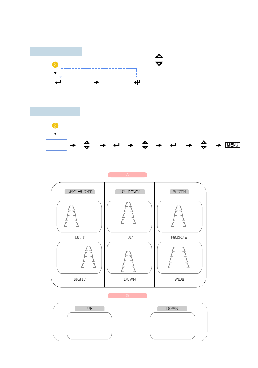
MARKER:[A;B;OFF]
System Setting
2
MARKER
selecting
MARKER SETTING
2
MARKER
SETTING
LEFT-RIGHT
Trigger1,2
UP/DN
SELECT
option selecting
UP / DN SELECT UP / DN SELECT UP / DN
shifting selecting shifting option setting selecting exit
A
LEFT
UP-DOWN
UP
WIDTH
NARROW
RIGHT
UP DOWN
DOWN
B
- 9 -
WIDE
Page 10
System Setting
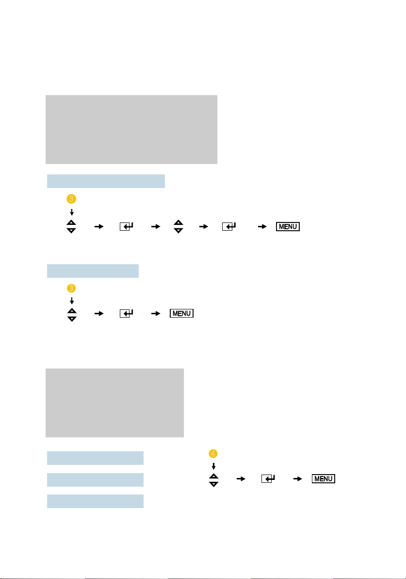
3. AUTO SCAN SETTING
3. AUTO SCAN SETTING
AUTO SCAN
CAM1 SCAN TIME
CAM2 SCAN TIME
AUTO SCAN TIME SETTING
3
UP / DN SELECT UP / DN SELECT MENU
shifting option setting shifting option setting exit
AUTO SCAN:[ON;OFF]
3
UP / DN SELECT MENU
shifting option setting exit
[ ON;OFF ]
[0~20sec ]
[0~20sec ]
4. DAY/NIGHT SETTING
3. DAY/NIGHT SETTING
SENSOR
SENSITIVITY
NIGHT BRIGHT
[ ON:OFF ]
[0~60 ]
[0~60 ]
SENSOR: [ON;OFF]
SENSITIVITY: [0~60]
NIGHT BRIGHT: [0~60]
4
UP / DN SELECT MENU
shifting option setting exit
- 10 -
Page 11
System Setting
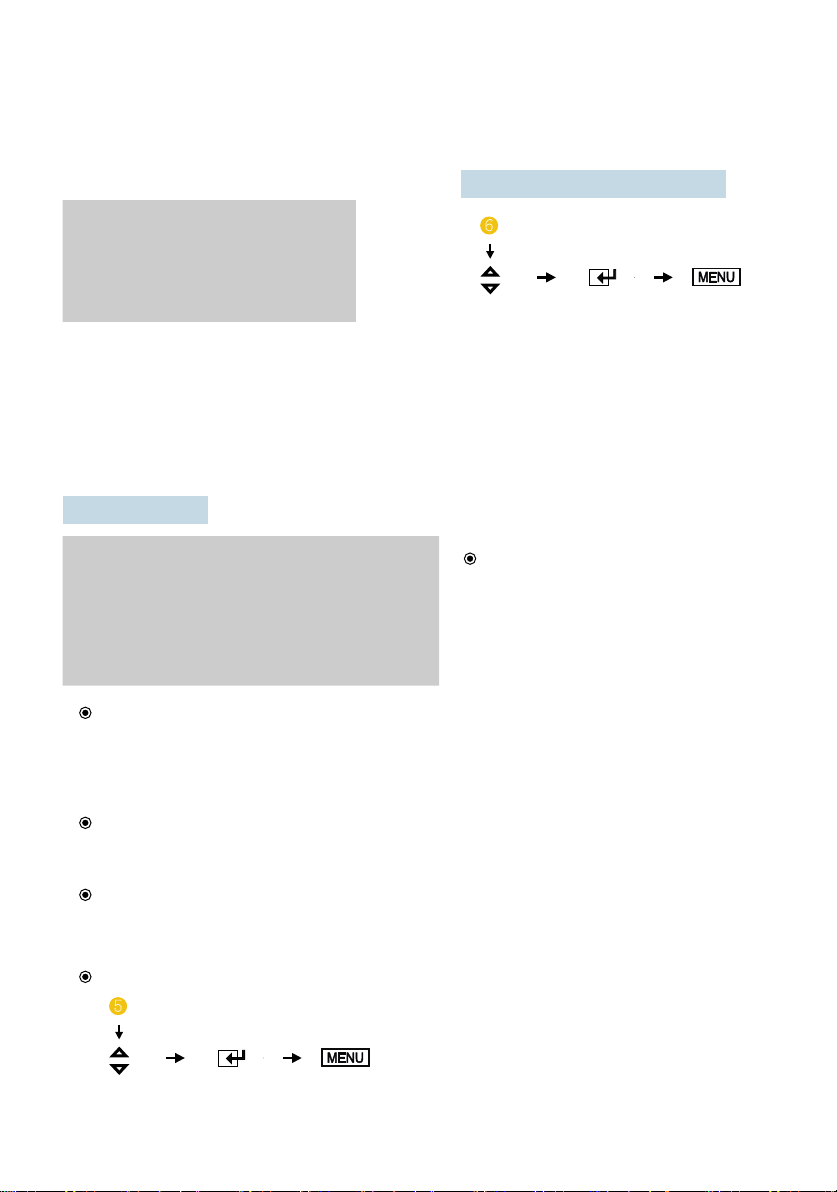
5. ADCANCED MENU
AUTO POWER:[ON;AUTO;OFF]
5. ADVANCED MENU
AUTO POWER [ON;AUTO;OFF]
SPEED SWITCH
FACTORY RESET
* NOTE
- Auto Setting Monitor keeps the last setting in memory: Monitor will start up "Power-on" mode or
"Stand- by" mode according to its last mode before the ignition key off.
- Off Setting Monitor keeps "Stand- by" setting regardless of the last mode before the ignition key off.
- On setting: Monitor will be turned on automatically when ignition key on regardless of the last mode
of the monitor before the ignition key off.
SPEED SWITCH
SPEED SWITCH
SPEED SWITCH : [ON;OFF]
FREQUENCY : [10~1000]
UNDER FREQ CH
OVER FREQ DISPLAY
OVER FREQ CH : [CAM1;CAM2]
FREQUENCY: [10~1000]
* NOTE
- Select activated frequency 10~1000Hz.
- Press “SELECT” button short for 1Hz frequency steps change.
- Press “SELECT” button long for 10Hz frequency steps change.
: [CAM1;CAM2]
: [ON;OFF]
6
UP / DN SELECT MENU
shifting option setting exit
SPEED SWITCH: [ON;OFF]
* NOTE
- Select “ON” for enter into
the function.
- Select “OFF” for get out the
function.
UNDER FREQ CH: [CAM1;CAM2]
* NOTE
* NOTE
UP / DN SELECT MENU
shifting option setting exit
- Activates selected channel when input is lower frequency than frequency setting.
OVER FREQ DISPLAY: [ON;OFF]
- Select :ON” for displaying image when input is higher frequency
than frequency setting.
OVER FREQ CH: [CAM1;CAM2]
5
- 11 -
* NOTE
- Activates channel image when
input is higher frequency than
frequency setting.
Page 12
System Setting
EXAMPLE OF SPEED SWITCH FUNCTION:
* The orange wire needs to be connected with the vehicle’s tacho signal and via
MENU the SPEED SWITCH needs to be selected ON.
* Adjust FREQUENCY into 67Hz. At this setting (and most common used tacho
signal), the selected camera will be displayed during a speed of 0~33km/h.
* Select the concerning camera via “UNDER FREQUENCY CH;” (At different type
tacho signals, the FREQUENCY needs to be adjusted into higher or lower value
than this example)
* Over 33km/h (72Hz), the selected camera will be switched OFF automatically.
When the speed slows down, then the selected camera will be switched ON
automatically again at 30km/h. Instead of automatic switch OFF at a speed over
33km/h it is also possible to activate another video source, such as the image of a second
camera or a navigation picture from an optional navigation computer. In this case,
user needs to select “OVER FREQUENCY DISPLAY: ON” and user needs to select
“OVER FREQUENCY CH”
* In case of TRIGGER activation during “SPEED SWITCH ON” mode, than
TRIGGER 1,2 will overrule “SPEED SWITCH” function.
FACTORY RESET
5
UP / DN SELECT
shifting option setting
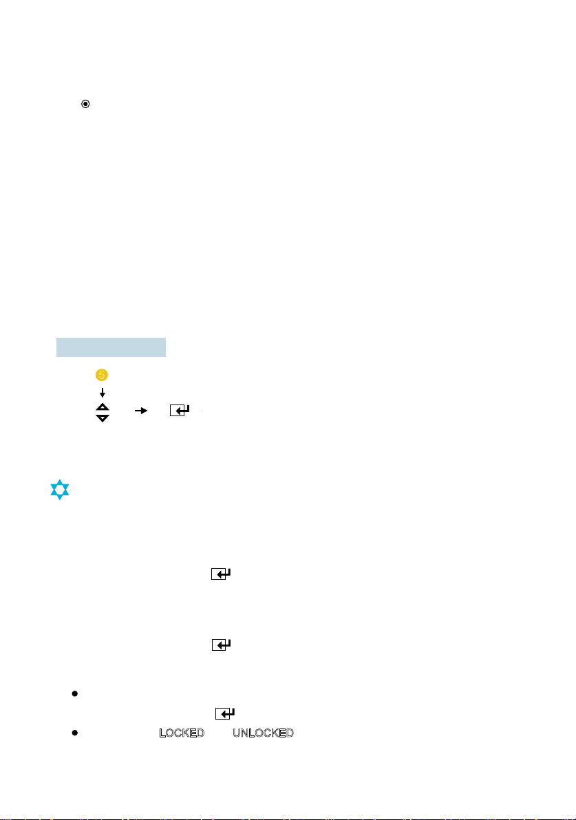
LOCK ON/FF FUNCTION
LOCK ON/FF FUNCTION
The set up menu can be prevention against unauthorized users.
LOCK ON mode
At Power-ON mode, hold icon pressed for 10 seconds to set up LOCK ON Function.
When [ LOCKED ] is displayed on the screen, user can use [ POWER, SELECT, VOLUME ]
buttons only and use can do setting for PICTURE menu.(Short key)
LOCK OFF mode
At Power-ON mode, hold icon pressed for 10 seconds to set up LOCK OFF Function.
When [ UNLOCKED ] is displayed on the screen, user can use all functions of the set up menu.
When [ LOCKED ] or [ UNLOCKED ] is displayed on the screen, user can select [ LOCKED ] or
[UNLOCKED] by pressing icon.
After selection [ LOCKED
Then, press POWER button again to activate the proper LOCK ON/OFF function.
] or [ UNLOCKED ] , press POWER button.
- 12 -
Page 13
Installation
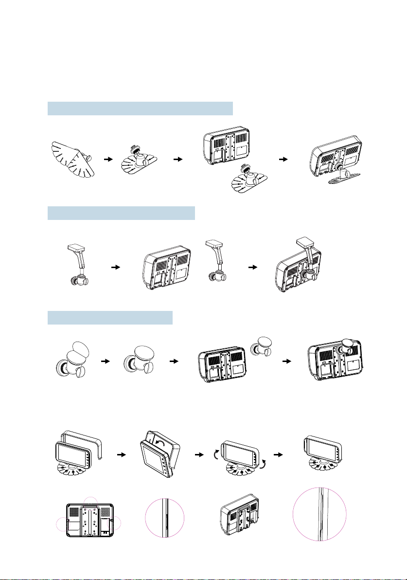
1. Monitor Fixing Method
1) STAND BRACKET ,RAILS TYPE(INCLUDED)
2) ROOF MOUNT BRACKET : OPTION
3) WINDOW BRACKET: OPTION
2. Sunvisor Mounting Method
- 13 -
Page 14
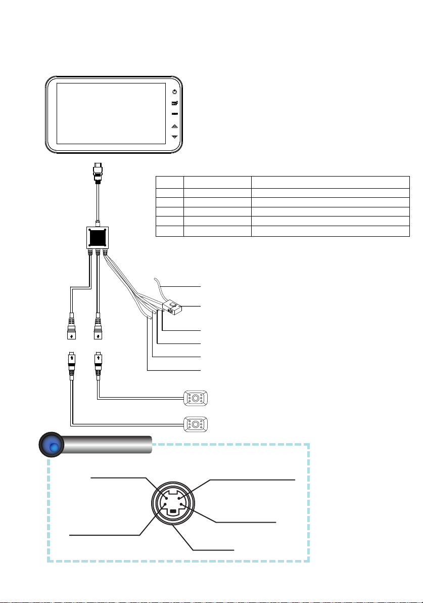
CAM1 CAM2
Connection
POWER/TRIGGER WIRE FUNCTIONS
REF# WIRE COLOR DESCRIPTION
1 RED POWER IN DC (12 TO 30V)
2 WHITE TRIGGER2 (12 TO 30V)
3 GREEN TRIGGER1 (12 TO 30V highest priority)
4 ORANGE SPEED SWITCH (TACHO SIGNAL)
5 BLACK GROUND
RED (POWER 12 TO 30V, via ignition)
FUSE (3A)
BLACK (GROUND)
ORANGE (SPEED SWITCH;TACHO SIGANL)
WHITE (TRIGGER 2: 12 TO 30V)
GREEN (TRIGGER 1 : 12 TO 30V, highest priority)
CAMERA INPUT
AUDIO INPUT
+12V DC OUTPUT
POWER
camera (option)
camera (option)
+12V DC OUTPUT
HEATER & SHUTTER
VIDEO INPUT
GROUND
- 14 -
Page 15

MXN-7DM
Specifications
Power Input
Power Consumption
Video System
Panel
Resolution
Format
Camera input(2CH)
Operating Temp.
Storage Temp.
Vibration
OSD Control
DC 12V~30V
Max. 12Watt
NTSC / PAL compatible
7" Digital
800 (H) x 480 (V) x 3 (RGB)
16:9 wide
Mini DIN 4P, 1Vp-p 75Ω (MXN configuration)
-30℃ ~ +80℃
-40℃ ~ +90℃
6G
Day & Night Sensor & Sharpness
Bright, Contrast, Color, Tint
Mirror/ Normal, Day/ Night Mode/ Scale
*Individual Control per Channel available
Dimension
Weight
Supplied acc`y
195 (W) x 109 (D) x 22( H) mm
Approx. 410g
Camera Input Cable
Screw Kit
Stand Bracket
Sun Visor
Instruction Manual
- 15 -
: (1)
: (1)
: (1)
: (1)
: (1)
Page 16
THIS SYMBOL MEANS DO NOT DISPOSE OF
AS MUNICIPAL WASTE.
RE-USE OR RECYCLE WHEREVER POSSIBLE.
ELECTRICAL / ELECTRONIC COMPONENTS MAY
CONTAIN SUBSTANCES WHICH ARE HARMFUL TO
THE ENVIRONMENT.
FOR ENVIRONMENTALLY SOUND METHODS OF
DISPOSAL, PLEASE CONTACT YOUR LOCAL
GOVERNMENT AUTHORITY.
printed in korea
 Loading...