

Page 1
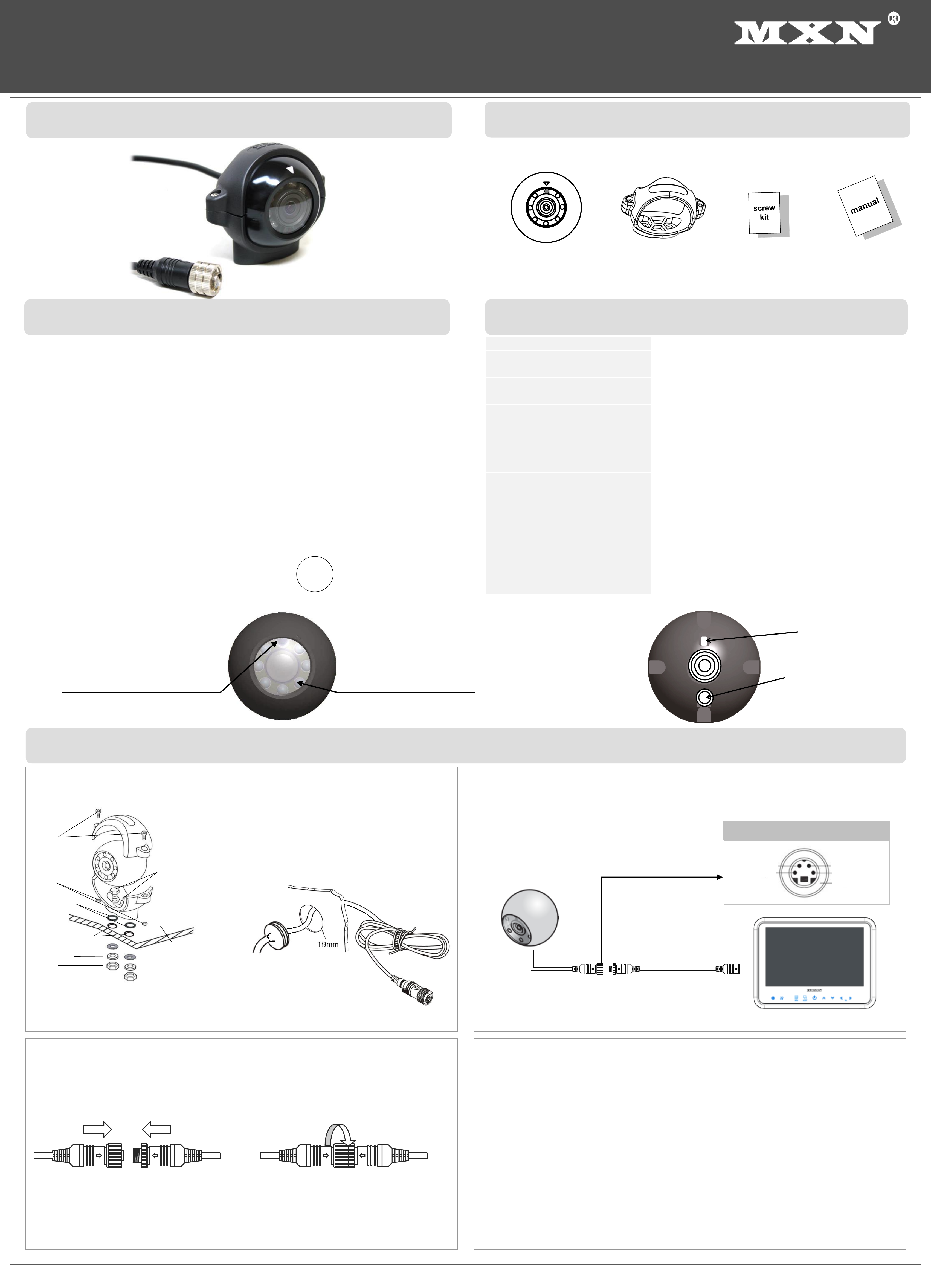
◈ MXN22C Camera
◈ Installation
◈ Features
◈ Technical Specifications
* Design And Specifications Are Subject To Change Without Notice.
1. Before making the connection, disconnect the ground terminal from the battery
to avoid short circuits.
2. The plugs should be fully inserted into the connectors or jacks.
A loose connection may cause malfunctioning of the unit.
3. A damaged cable may affect the operation of the camera and may even cause
a malfunction of the camera or monitor: Avoid a damaged cable!
4. Protect the cable by using a guide tube, pipe or run the cable inside the vehicle
as much as possible. Caution! Run the cable in natural shapes in order to
prevent cable breaks.
5. Preferably use an acid free grease in between the waterproof screw type
connectors and tighten them firmly eachother.
▪ Caution !!
▪ Securing cable connection
Note!
The warranty will not be valid if the problem is related to moist / corrosion in the connector.
▪ Front View
▪ Rear View
Camera Bracket x 1
Manual x 1
Camera x 1
Screw kit x 1
IR LED’s
Day/Night sensor
1. Match the arrow marks and
press the connectors together.
2. Screw the camera connector
up clockwise.
3. Tighten cable connection firmly
in order to prevent water ingress.
▪ Wiring to Monitor
Run the cable from the camera to the
monitor.
Extension cable
(Not supplied)
Instruction Manual
130 Degree Wide View, Autoheated, Color Camera
MXN22C
Heater function
(9~12V DC)
Audio out
Video out
Power (9~48V DC)
GROUND
Camera pin configuration
▪ Camera Assembly
1. Fix the supplied camera bracket to the vehicle.
2. Fix the bracket with camera according to drawing.
3. Adjust the viewing angle of the camera and fasten the screws firmly.
▪ Cable grommet
Drill a suitable hole (approx. Ø 19mm) and insert the
cable grommet.
Just before final fixation, please apply a proper sealant
(for prevention) between the hole and the grommet and
also between the cable and the grommet.
Monitor
Built-in Microphone
Normal/Mirror Image
switch
◈ Contents
Image Sensor :
1/3.2” Color SONY CMOS(Exmor)
Picture elements :
PAL, 1.23Mega pixels(1280x960)
Resolution : 750TV lines
S/N ratio : Minimum 45dB (at AGC off)
Minimum illumination : 0 Lux (IR LED’s on)
Power range : DC 9 ~ 48V
Power consumption : DC 12V, 265mA (heater on)
DC 12V, 165mA (heater off)
Operating temperature : -40ºC to +80ºC
Viewing angle : 130˚(D) x 102˚(H) x 76˚(V)
Dimension : Ø 52mm, 72(W) x 51(D) x 63(H) incl. bracket
Weight :
Supplied Accessories :
Approx. 215g
Camera Bracket (1)
Stainless M6 x 25mm bolt + M6 nut (2 + 2)
Stainless M3 x 12mm bolt + M3 nut (2 + 2)
Stainless M4 x 16mm tapping screw (2)
Rubber washer + stainless metal washer (2 + 2)
Rubber O-Ring (2)
Allen wrench 3mm (1)
▪ Best picture quality (in combination with Digital LCD monitor)
▪ High resolution CMOS camera (1.23Mega pixels)
▪ 1/3.2” Color CMOS high resolution image sensor
▪ IP69K Waterproof Rating
▪ Built-in IR LED’s
▪ Diagonal 130˚ viewing
▪ Normal/Mirror Image adjustable
▪ Built-in Microphone (for one-way audio)
▪ Multi purpose (Frontview, sideview, rearview, surveillance, etc)
▪ Built-in Automatic Heater (below +10˚C)
▪ Anti-corrosive 3-fold coating
▪ Temp. -40˚C ~ 80˚C
▪ Vibration resistant
▪ CE and EMC approved
Optional versions of model MXN22C:
MXN22C-078 78˚(D) x 62.0˚(H) x 45.0˚(V)
MXN22C-040 40˚(D) x 30.9˚(H) x 23.2˚(V)
MXN22C-020 20˚(D) x 17.0˚(H) x 12.8˚(V)
10R-05-6368
E9
M3 bolt
M6 nut
Metal washer
Rubber washer
Rubber O-ring
M3 nut
M6 bolt
Installation surface
Ø 6mm Drilling holes
Page 2
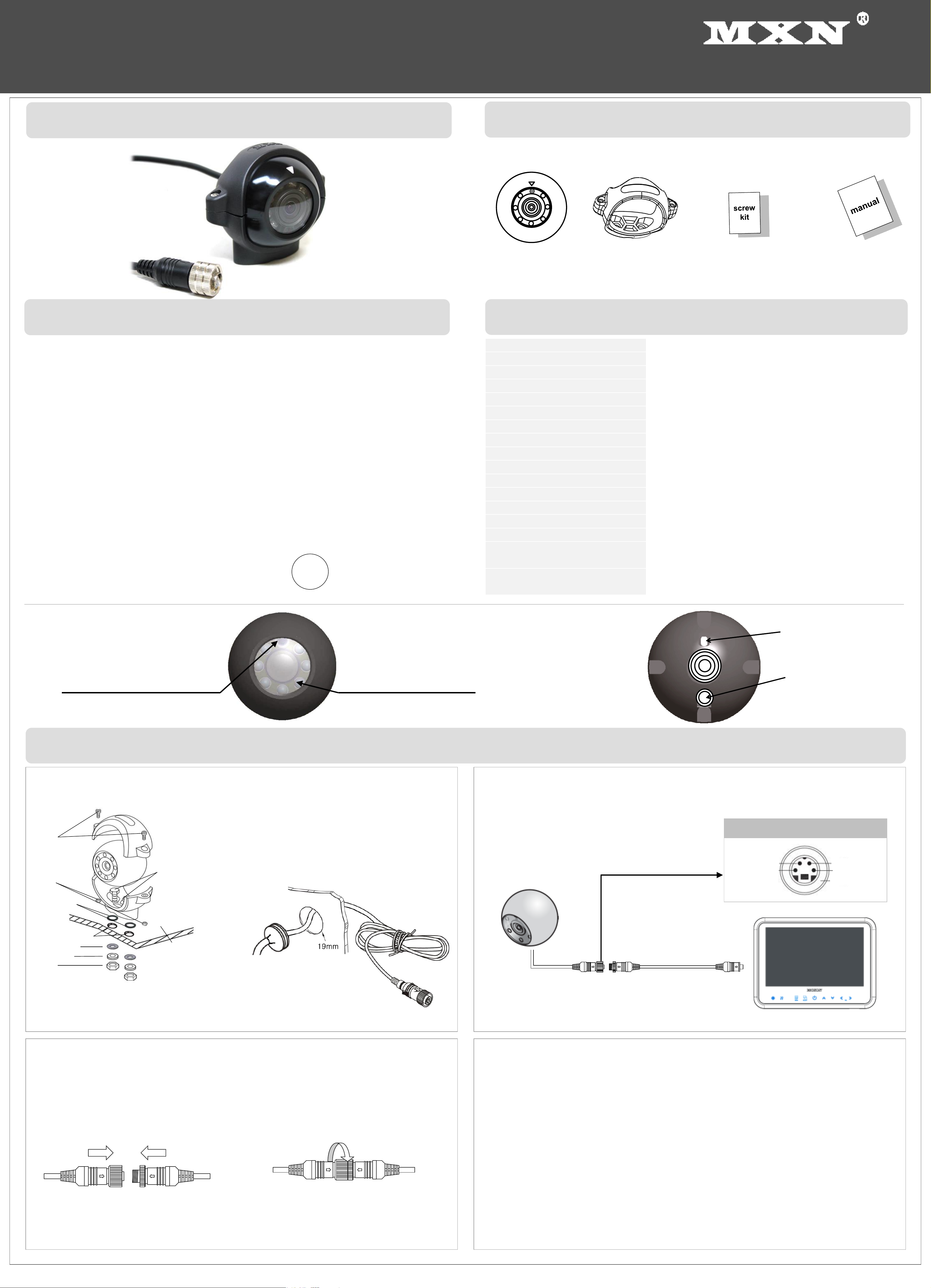
◈ MXN22C Camera
◈ KENMERKEN
◈ TECHNISCHE SPECIFICATIES
▪ VOORAANZICHT
▪ ACHTERAANZICHT
Camera bracket x 1
Handleiding x 1
Camera x 1
Boutjes/schroefjes set x 1
Infra-rood LED’s
Dag/Nacht sensor
Installatie Handleiding
130 Graden, Automatisch verwarmde, kleuren Camera
MXN22C
Ingebouwde microfoon
Normaal-/Spiegelbeeld
schakelaar
◈ INHOUD
▪ Best haalbare beeldkwaliteit. (in combinatie met digitaal LCD)
▪ 1/3.2” CMOS, hoge resolutie kleuren beeldsensor. (1.23Mega pixels)
▪ IP69 waterdicht
▪ Ingebouwde Infra Rood LED's
▪ Diagonaal 130˚ lenshoek
▪ Normaal-/Spiegelbeeld omschakelbaar
▪ Ingebouwde microfoon
▪ Geschikt voor diverse toepassingen (frontzicht, zijzicht, achterzicht, bewaking, etc)
▪ Ingebouwde verwarming met thermostaat (schakelt AAN onder +10˚C)
▪ 3-Laags anti-corrosie coating
▪ Te gebruiken bij -40˚C ~ 80˚C
▪ Schokbestendig
▪ CE en EMC gekeurd
Optionele varianten van model MXN22C:
MXN22C-078 78˚(D) x 62.0˚(H) x 45.0˚(V)
MXN22C-040 40˚(D) x 30.9˚(H) x 23.2˚(V)
MXN22C-020 20˚(D) x 17.0˚(H) x 12.8˚(V)
10R-05-6368
E9
◈ INSTALLATIE
* Ontwerp en specicaties kunnen zonder voorafgaande kennisgeving gewijzigd worden.
1. Maak de min-pool van de accu los om kortsluiting te voorkomen, voordat u de
verbindingen tot stand brengt.
2. Voor een juiste werking van de unit dienen de connectoren zorgvuldig met
elkaar verbonden te worden.
3. Een beschadigde kabel kan de werking van de camera beïnvloeden en zelfs een
defect van de camera en/of monitor tot gevolg hebben; voorkom dit!
4. Bescherm de kabel d.m.v. het gebruik van een geleidebuis/ leiding en/ of door
de kabel zo veel mogelijk binnen het voertuig door te halen. Let op! Voorkom
kabelbreuken door de kabel in natuurlijke vormen te installeren.
5. Gebruik bij voorkeur een zuurvrije vaseline tussen de schroefverbindingen in
de kabel en draai deze verbindingen stevig aan.
▪ Let op!!
▪ Camera montage
▪ Kabelverbinding
NB!
Garantie wordt uitgesloten indien het probleem te wijten valt aan vocht/corrosie in de connector.
1. Bevestig de camera bracket op de gewenste plek van het voertuig.
2. Voeg de camera en bracket samen volgens bovenstaande tekening.
3. Bepaal de kijkrichting van de camera en draai de M3 boutjes stevig aan.
1. Houd de pijlmarkeringspunten in
één lijn en druk de connectoren
rechtlijnig in elkaar.
2. Draai de moer van de cameraconnector
met de klok mee aan, terwijl u gelijktijdig
de pijlmarkeringspunten stevig naar
elkaar toe gedrukt houdt.
3. Draai deze verbinding stevig aan ter
voorkoming van inwatering!
▪ Kabel naar de monitor
Verwarming
(9~12V DC)
Audio out
Video out
Voeding (9~48V DC)
Massa
Camera pin configuratie
Leid de kabel van de camera naar de
monitor.
Verlengkabel
(optioneel)
Boor op de juiste locatie een gat (circa Ø 19mm) en
plaats hierin de rubber kabeldoorvoer. Zodra de
bekabeling definitief gepositioneerd is, pas vervolgens
preventief een geschikte afdichtende kit (sealer) toe,
tussen het gat en het rubber en tussen de kabel en het
rubber.
▪ Rubber kabeldoorvoer
Monitor
Beeld Sensor : 1/3.2” kleuren SONY CMOS (Exmor)
Aantal Pixels : PAL, 1.23Mega pixels(1280x960)
Resolutie : 750 TV Lijnen
Signaal-ruisverhouding : Minimaal 45dB (tijdens AGC uit)
Licht benodigdheid : 0 Lux (IR LED’s AAN)
Voeding : DC 9 ~ 48V
Verbruik : DC 12V, 265mA (verwarming AAN)
DC 12V, 165mA (verwarming UIT)
Werkt bij : -40ºC tot +80ºC
Lenshoek : 130˚(D) x 102˚(H) x 76˚(V)
Diameter, afmeting camera : Ø 52mm, 72(B) x 51(D) x 63(H) incl. bracket
Gewicht : Ca. 215g
Accessoires : Camera bracket (1)
M6 x 25mm bout + M6 moer, RVS (2 + 2)
M3 x 12mm bout + M3 moer, RVS (2 + 2)
M4 x 16mm parker, RVS (2)
Rubber ring + metalen ring, RVS (2 + 2)
Rubber O-ring (2)
Inbussleutel 3mm (1)
M3 bout
M6 moer
Metalen ring
Rubber ring
Rubber O-ring
M3 moer
M6 bout
Installatie oppervlak
Ø 6mm Boorgat
 Loading...