

Page 1
OWNER’S MANUAL
PLEASE READ CAREFULLY BEFORE
USING THIS PRODUCT.
10.1” DIGITAL 3CH LCD
ALL ROUND VISION MONITOR
Model: MXN10-TVI
Design and specifications are subject to change without notice.
Page 2

INDEX
PACKAGE CONTENTS
OPERATION
03
04
SYSTEM SETTINGS
MENU STRUCTURE 05
FUNCTION 06
PICTURE MENU 07
NORMAL/MIRROR 07
AUDIO 08
TRIGGER AUDIO 08
CAMERA TRIGGER 09
DISTANCE MARKER 09
MARKER 09
DISTANCE MARKER ADJUSTMENT 10
AUTO PICTURE SCAN 11
CAMERA NAME 11
SPEED SWITCH 12
MENU
SPLIT 13
MANUAL SELECTION 13
MENU LOCK ON/OFF FUNCTION 14
AUTO PICTURE SCAN ON/OFF FUNCTION 14
CONNECTIONS
CAMERA INPUT 15
INSTALLATION
BRACKET 16
INSTALLATION OF HEAVY DUTY MOUNTING BRACKETS 17
SPECIFICATIONS
18
Page 3
PACKAGE CONTENTS
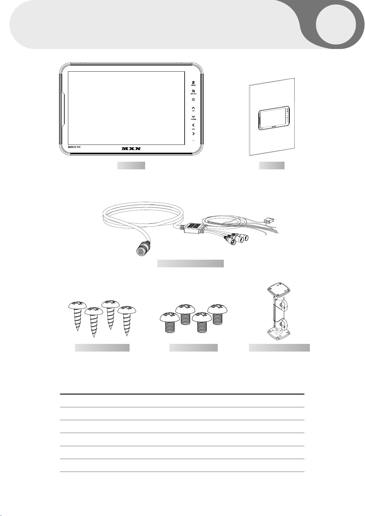
MONITOR MANUAL
OWNER’S MANUAL
PLEASE READ CAREFULLY BEFORE
USING THIS PRODUCT.
10.1” DIGITAL 3-CHANNEL SWITCHING LCD MONITOR
Model: MXN10-TVI
Design and specifications are subject to change without notice.
03
03
CAMERA INPUT CABLE
BRACKET SCREWS MOUNT SCREWS HEAVY DUTY MOUNT
ITEM Q’TY
MONITOR 1
CAMERA INPUT CABLE 1
HEAVY DUTY MOUNT 1
MOUNT SCREWS (Machine Screw, M5 / 12mm) PH M5x12 4
BRACKET SCREWS (Tapping Screw, M5 / 25mm) TH 1, M5x25 4
MANUAL 1
MXN10-TVI Owner's Manual
Page 4
04
OPERATION
A
B
C
D
E
F
G
H
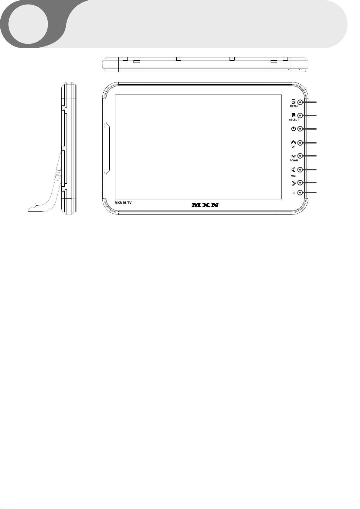
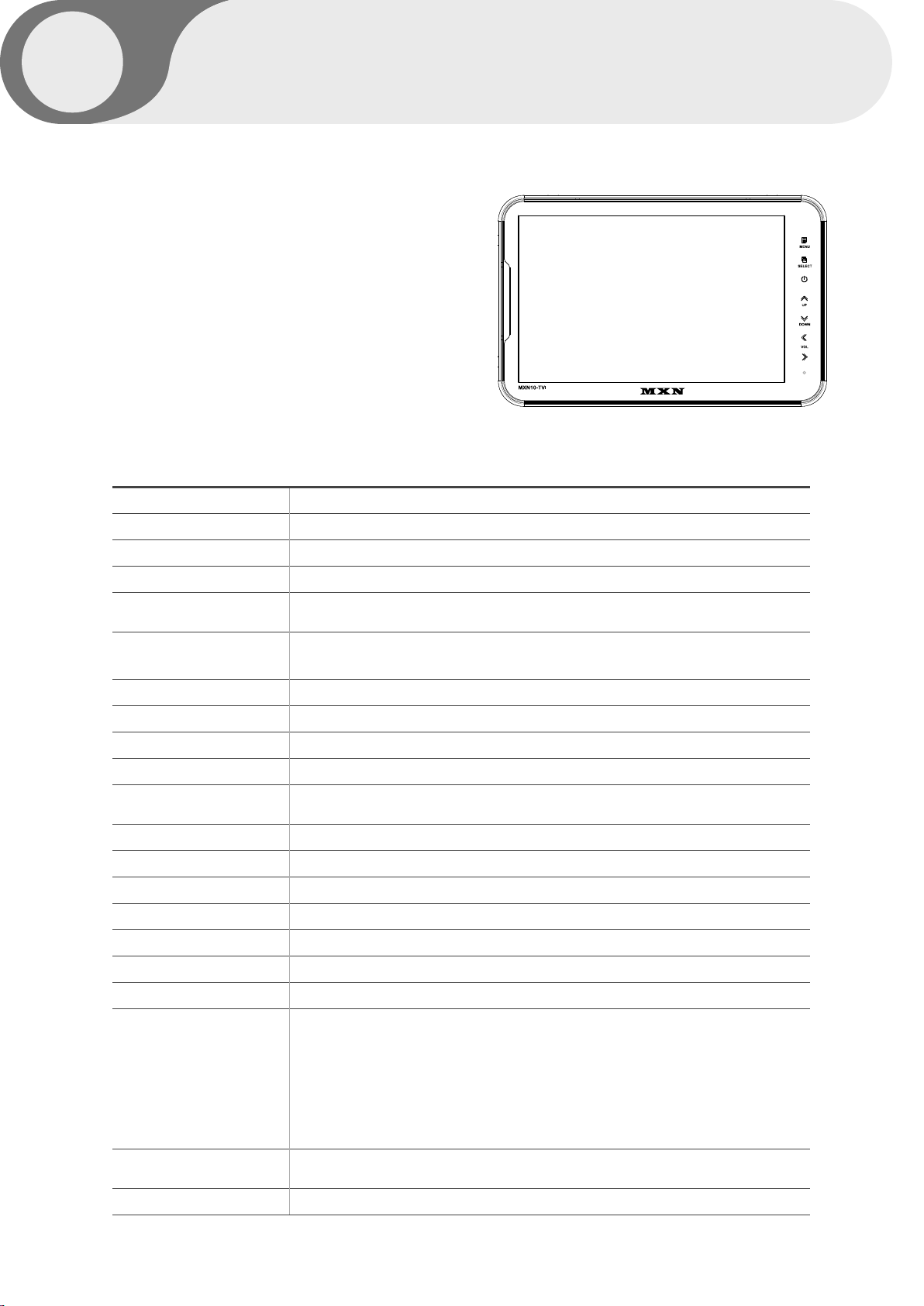
A. MENU
Press [MENU] button for system settings.
B. SELECT
Press [SELECT] button to select the respective channel.
[CAM1 - CAM2 - CAM3 - SPLIT].
C. POWER
Press [POWER] button to turn on/off the monitor.
D. UP
Press [UP] button to navigate the menu for system settings.
E. DOWN
Press [DOWN] button to navigate the menu for system settings.
F. LEFT
Press [LEFT] button to adjust the monitor volume.
Use [LEFT] button to change OSD setting during system settings.
G. RIGHT
Press [RIGHT] button to adjust the monitor volume.
Use [RIGHT] button to change OSD setting during system settings.
H. DAY/NIGHT SENSOR (CDS)
Automatic brightness control sensor
10.1” HD LCD MONITOR
Page 5
SYSTEM SETTINGS
FUNCTION
PICTURE
NORMAL/MIRROR
AUDIO
TRIGGER AUDIO
CAMERA TRIGGER
DISTANCE MARKER
AUTO PICTURE SCAN
CAMERA NAME
SPEED SWITCH
SPLIT
MANUAL SELECTION
05
05
MENU STRUCTURE
Change the setting value by pressing the MENU button.
FUNCTION
Set functions on the monitor.
PICTURE
Set the color and brightness on the monitor.
NORMAL/MIRROR
Input video can be reversed
AUDIO
Set the audio ON/OFF.
TRIGGER AUDIO
Set the audio ON/OFF when entering the TRIGGER signal.
CAMERA TRIGGER
You can adjust the Screen settings with the corresponding TRIGGER signal is on.
DISTANCE MARKER
DISTANCE MARKER can be set according to the TRIGGER signal input.
AUTO PICTURE SCAN
Set the automatic sequence switching time.
CAMERA NAME
Set the camera name.
SPEED SWITCH
By receiving TACHO signal, you can set the operation at the corresponding frequency.
SPLIT
Display the camera video at the set position on the SPLIT screen.
MANUAL SELECTION
When the SELECTION button is pressed, the output screen is set.
MXN10-TVI Owner's Manual
Page 6
06
SYSTEM SETTINGS
LANGUAGE
SYSTEM
DIMMER
DAY BRIGHT
NIGHT BRIGHT
AUTO POWER
BUZZER
RESET
SYSTEM INFO
ENGLISH
AUTO
AUTO
90
50
OFF
ON
>>
VER 1.00
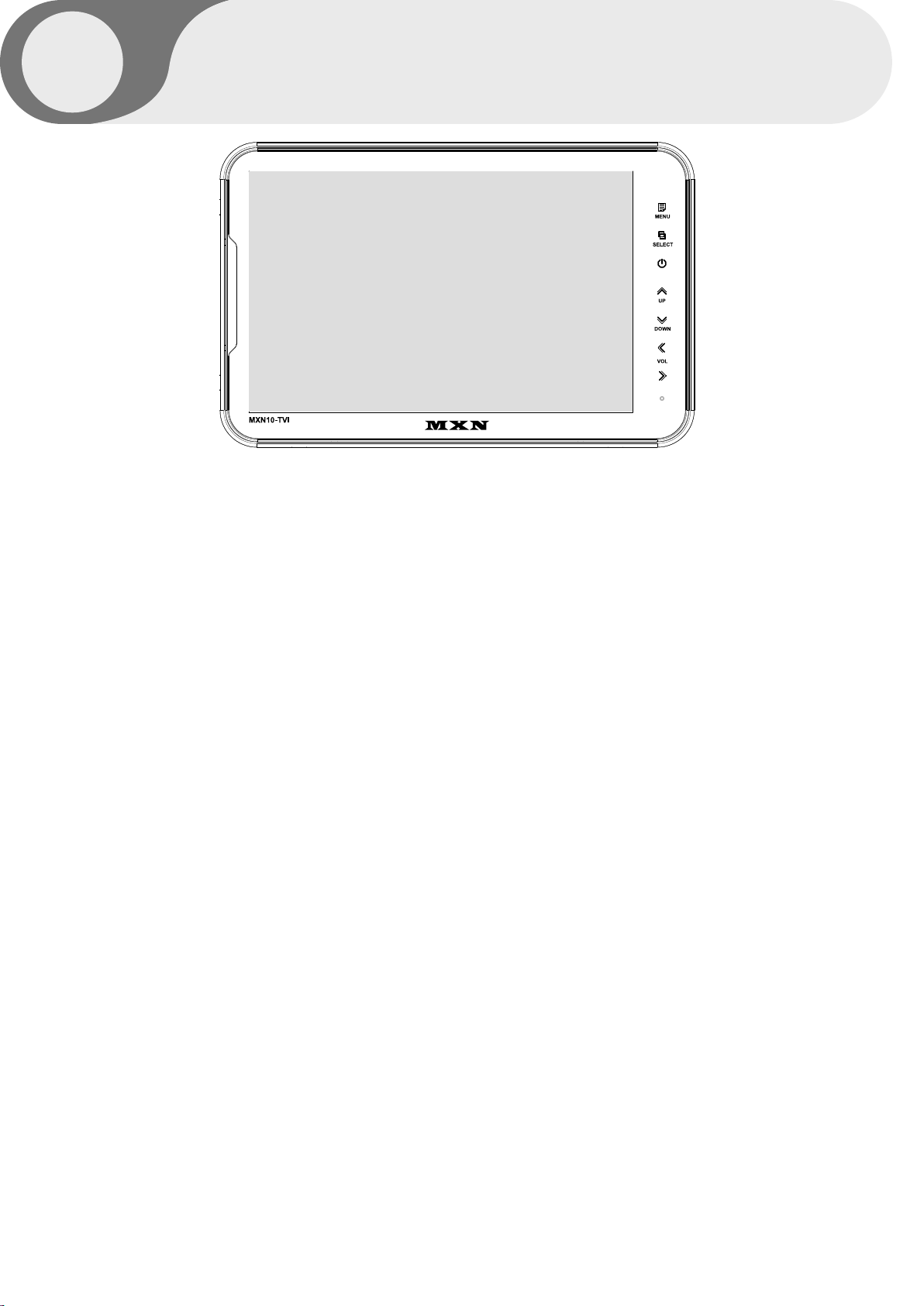
FUNCTION
LANGUAGE
Provide 6 Multi-lingual OSD [ENGLISH, SWEDISH, DANISH, NORWEGIAN, DUTCH, FINNISH].
Select the preferred LANGUAGE.
SYSTEM
Select AUTO/TVI/AHD/NTSC/PAL
DIMMER (Automatic Brightness Control)
Select AUTO or OFF to enable Automatic or Manual brightness control.
REMARK: By activating the DIMMER AUTO function,
the monitor adjusts the brightness according to the environment.
DAY BRIGHT
Select the DIMMER as 『AUTO』, set the value of backlight on DAY mode(0~100).
NIGHT BRIGHT
Select the DIMMER as『AUTO』, set the value of backlight on NIGHT mode(0~100).
AUTO POWER
Select monitor activation functions as below.
[AUTO] The monitor remembers the last settings from its memory.
[ON] The monitor is turned on with the『Power-ON』mode automatically.
[OFF] The monitor is turned on with the『tSand-By』mode automatically.
BUZZER
Select BUZZER sound 『ON』 and 『OFF』.
RESET
Press “>>” button to enter the factory default settings.
SYSTEM INFO
Refers to the system information of the monitor.
10.1” HD LCD MONITOR
Page 7
SYSTEM SETTINGS
07
07
CONTRAST
BRIGHTNESS
COLOR
TINT
50
50
50
50
PICTURE MENU
Press [LEFT/RIGHT] button to adjust the PICTURE of the monitor.
PICTURE MENU is for the settings of PICTURE from CAM1, CAM2, CAM3, SPLIT MODE.
FISHEYE
When using the FISHEYE camera, 『ON』 will calibrate the screen on the FULL screen.
CAM1
CAM2
CAM3
NORMAL
NORMAL
NORMAL
NORMAL/MIRROR
Each camera picture (CAM1/CAM2/CAM3) can be switched between
NORMAL& MIRROR image.
MXN10-TVI Owner's Manual
Page 8
08
SYSTEM SETTINGS
CAM1
CAM2
CAM3
SPLIT
AUDIO
AUDIO
AUDIO
ON
ON
ON
ON
AUDIO
Audio ACTIVATED Mode in normal mode.
When the mode is [ON], audio will be on (activated)
When the mode is [OFF], audio will be off (mute).
TRIG1
TRIG2
TRIG3
SP SW
AUDIO
AUDIO
AUDIO
AUDIO
ENTER
ENTER
ENTER
ENTER
TRIGGER AUDIO
Audio ACTIVATED Mode in Trigger mode.
Choose the trigger and then press [ENTER].
The Audio settings menu will be shown as below.
TRIG1 AUDIO
VOLUME
ON
10
10.1” HD LCD MONITOR
When the mode is [ON], audio will be on (activated).
When the mode is [OFF], audio will be off (mute).
The user can adjust the volume.
Page 9
SYSTEM SETTINGS
09
09
TRIGGER1
TRIGGER2
TRIGGER3
TRIG1. DELAY
TRIG2. DELAY
TRIG3. DELAY
CAM1
CAM2
CAM3
2
2
2
CAMERA TRIGGER
TRIGGER 1/2/3 (Trigger source selection)
Select the required trigger source at CAM1/CAM2/CAM3/SPLIT
REMARK
TRIGGER PRIORITY: TRIGGER 1 > TRIGGER 2 > TRIGGER 3
TRIG. DELAY
When a TRIGGER wire is connected to a pulse DC power signal (e.g.direction indicator lights) then the
[TRIGGER DELAY] function avoids repeating ON/OFF of the monitor.
TRIGGER1
TRIGGER2
TRIGGER3
MARKER
ON
OFF
OFF
DISTANCE MARKER
Select ON to have DISTANCE MARKER for CAM1, CAM2, CAM3
DISTANCE MARKER is displayed as the trigger signal is activated.
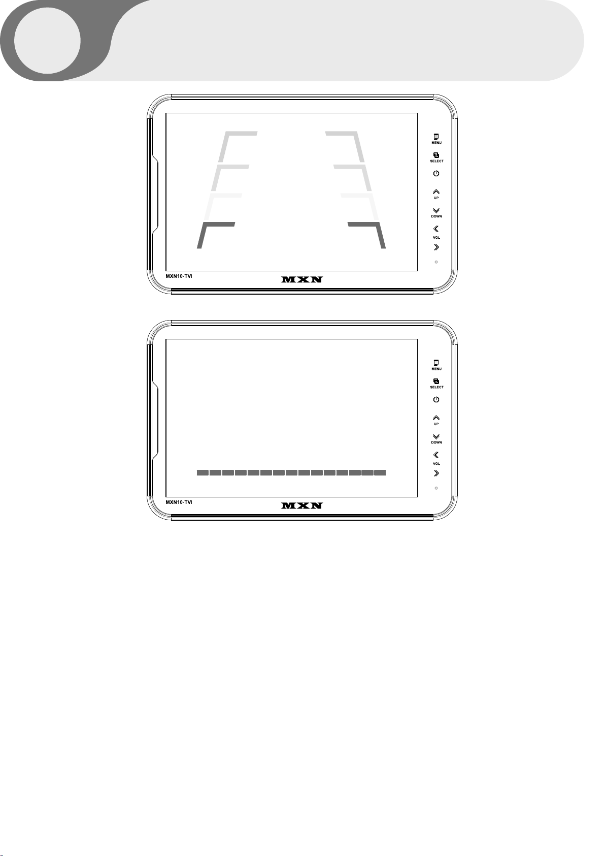
MARKER
Select of DISTANCE MARKER. or ___
MXN10-TVI Owner's Manual
Page 10
10
SYSTEM SETTINGS
Marker A
>>
Marker B
>>
DISTANCE MARKER ADJUSTMENT
Users can make adjustments by pressing the SELECT button in the menu.
(It is not available on the split mode screen)
Marker A- Parking line
The left/right/both markers will be selected in order each time you press the SELECT button.
When the marker is red it can be adjusted UP/DOWN or LEFT/RIGHT.
When both distance markers are RED, you can adjust both markers LEFT/RIGHT/UP/DOWN.
When the left distance marker is RED, the left marker can be adjusted LEFT/RIGHT.
When the right distance marker is RED, the right marker can be adjusted LEFT/RIGHT.
Marker B- Horizontal line
Users can adjust the line UP/DOWN.
Users can adjust the horizontal line by pressing [UP/DOWN] buttons.
10.1” HD LCD MONITOR
Page 11
SYSTEM SETTINGS
11
11
AUTO SCAN
CAM1 SCAN TIME
CAM2 SCAN TIME
CAM3 SCAN TIME
SPLIT SCAN TIME
OFF
5
5
5
5
AUTO PICTURE SCAN
Each scanning time of CAM1/CAM2/CAM3/SPLIT can be managed.
REMARK
If the SCAN TIME is set as[0], monitor skips its channel during scanning.
Press [UP] button for 4 seconds to ACTIVATE / INACTIVATE auto scanning function.
CAM NAME DISPLAY
CAM1 NAME
CAM2 NAME
CAM3 NAME
ON
CAM1
CAM2
CAM3
CAMERA NAME
CAMERA NAME can be selected as CAM1, 2, 3/REAR/LEFT/RIGHT/FRONT.
MXN10-TVI Owner's Manual
Page 12
12
SYSTEM SETTINGS
SPEED SWITCH
FREQUENCY
UNDER FREQUENCY CAM
OVER FREQUENCY DISPLAY
OVER FREQUENCY CAM
OFF
67Hz
CAM3
OFF
CAM1
SPEED SWITCH
The orange wire needs to be connected with the vehicle’s tacho signal and via MENU the
SPEED SWITCH needs to be selected ON. At FREQUENCY 67Hz setting (and the most common
used tacho signal) the selected camera will be displayed during a speed of 0~33km/h.
Select the concerning camera via『UNDER FREQUENCY CAM』 (At a different type of tacho
signals the FREQUENCY needs to be adjusted higher or lower than the example)
Over 33km/h (72Hz) the selected camera will be switched OFF automatically. When the speed
slows down, then the selected camera will be switched ON automatically again at 30km/h.
Instead of automatic switch OFF at a speed over 33km/h it is also possible to activate another
video source, such as a navigation picture from an optional navigation computer.
In this case user needs to select 『OVER FREQUENCY DISPLAY: ON』 and user needs to select
『OVER FREQUENCY CAM』
In case of TRIGGER activation during 『SPEED SWITCH ON』 mode,
then TRIGGERS 1 ~ 3 will overrule the 『SPEED SWITCH』 function.
10.1” HD LCD MONITOR
Page 13
SOURCE 1
SOURCE 2
AUDIO
MODE
MENU
CAM1
CAM2
CAM1
S1
13
13
S1
S2
S2
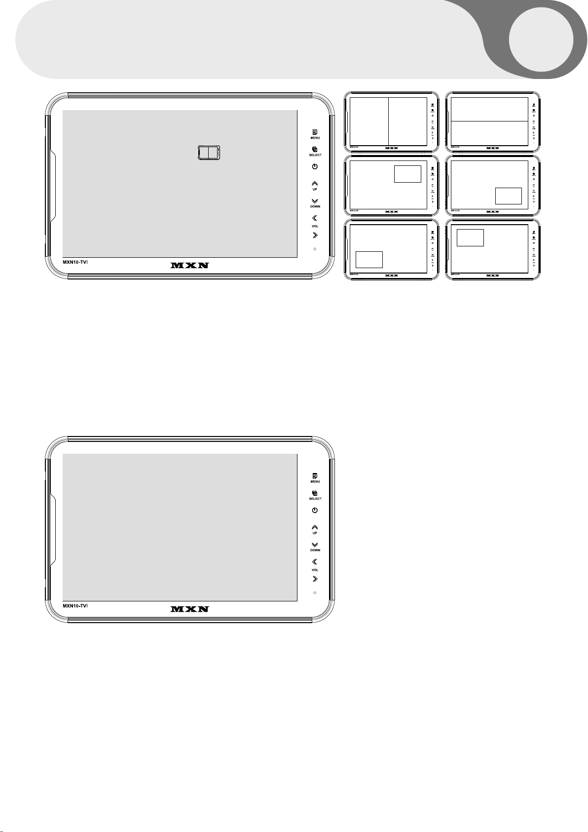
SPLIT configuration
SOURCE 1
SOURCE 2
AUDIO
MODE
Select S1 Camera (CAM1~CAM3).
Select S2 Camera (CAM1~CAM3).
Select SPLIT of Audio (CAM1~CAM3).
Select SPLIT MODE
S1
S2
S2
S1
S1
S2
S2
S1
CAM1
CAM2
CAM3
SPLIT
ON
ON
ON
ON
MANUAL SELECTION
When you manually press the channel select button, only the camera selected ON and
the display mode selected ON are displayed.
Manually pressing the channel select button skips the camera selected OFF and
display mode selected OFF.
[ NOTE ]
Triggers neglect the MANUAL SELECTION settings. In case of Trigger activation,
these ON/ OFF settings will be ignored.
MXN10-TVI Owner's Manual
Page 14
14
MENU LOCK ON/OFF FUNCTION
LOCK ON/OFF FUNCTION
The setup menu can be locked to ban any unauthorized users.
LOCK ON mode
At the Power-ON mode, press the [DOWN] button for 10 seconds to activate the LOCK ON function.
When [LOCKED] is displayed on the screen, the user can use only [POWER, SELECT, VOLUME]
buttons and the user can edit settings for the PICTURE menu.
LOCK OFF mode
At the Power-ON mode, press [DOWN] button for 10 seconds to activate the LOCK OFF function.
When [UNLOCKED] is displayed on the screen, the user can use all the functions of the setup menu.
SCAN ON/OFF FUNCTION
MENU
At the Power-ON mode,
press the [UP] button for 4 seconds to activate the Auto Scan Picture function.
During the Auto Scan Mode,
press the [UP] button for 4 seconds to deactivate Auto Scan Picture function.
SCAN CAM1 SCAN CAM2
SCAN CAM3 SCAN SPLIT
10.1” HD LCD MONITOR
Page 15
CONNECTIONS
MENU
SELECT
UP
DOWN
VOL
15
15
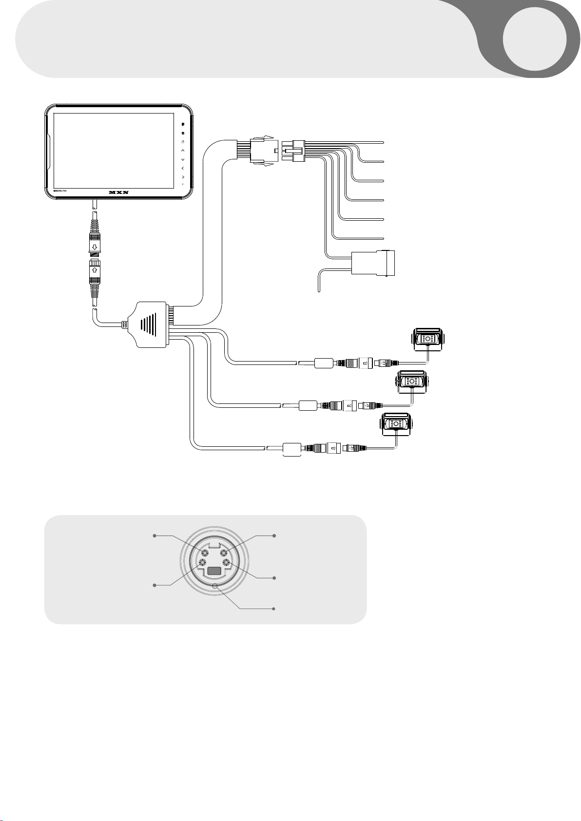
TRIGGER 1 - Green
TRIGGER 2 - White
TRIGGER 3 - Blue
Speed Switch (TACHO SIGNAL) - Orange
Shutter Memory 12/24V DC (+30) - Brown
Ground - Black
Main power 12V/24V DC via ignition (+15) - Red
CAMERA INPUT
AUDIO INPUT
+12V DC OUTPUT, POWER
Camera 3 (Option)
CA3
Camera 2 (Option)
CA2
Camera 1 (Option)
CA1
+9V DC OUTPUT,
HEATER & SHUTTER
VIDEO INPUT
GROUND
SHUTTER MEMORY FUNCTION
The function of "Shutter Memory" wire (brown wire) is to close the shutter of shutter camera
when Main +DC Power (+15) at the monitor's red wire is disconnected while the camera's
shutter is OPEN.
The "Shutter Memory" wire does not drain any current from the vehicle's battery within several
seconds after the camera's motorized shutter(s) are closed.
MXN10-TVI Owner's Manual
Page 16
16
12mm
7mm
5mm
2mm
60mm
INSTALLATION
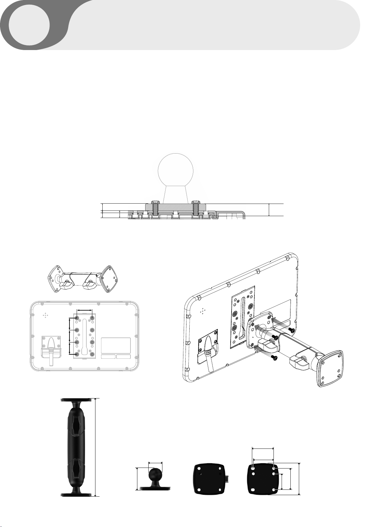
MONITOR installation with Standard Heavy Duty Mount Bracket
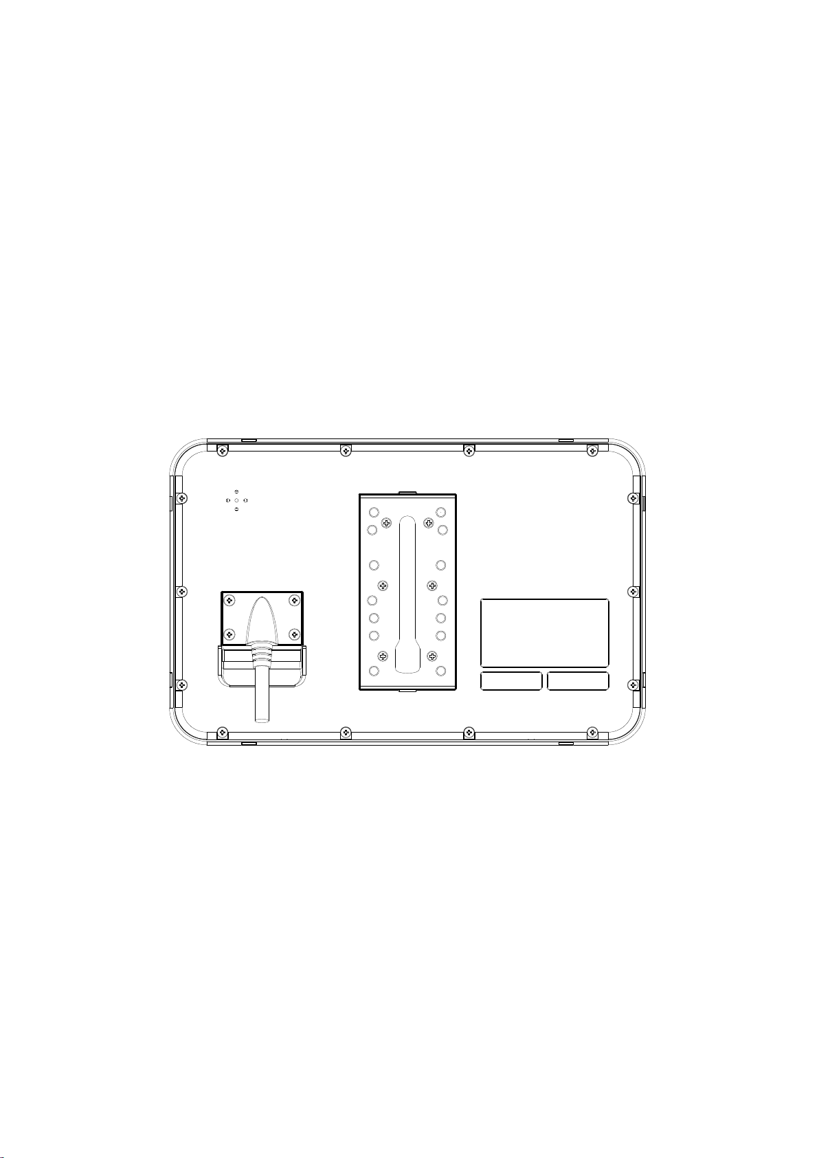
Fix the supplied Heavy Duty Mount Bracket into the monitor with the included screws.
Heavy Duty Mount Bracket’s angle fixation can be adjusted by tightening knobs.
[NOTE]
• The screw type : Mount-screw type, M5 (diameter of 5mm).
• The length of screw : Max. 12mm.
• Screw thread : 0.8mm.
Please make it sure to use the proper screws in order to avoid any damage into the monitor.
Screw length : 12mm
(HD Monitor bracket and screws as included)
[NOTE]
Maximum 7mm insert of screw into the monitor in case another type bracket and/or
screws are being applied. A deeper insert than 7mm will damage the monitor.
Heavy Duty Mount Bracket
38mm
30mm
30 30
7mm
10.1” HD LCD MONITOR
184mm
42mm
26mm
40mm
38mm
40mm
30mm
Page 17
INSTALLATION
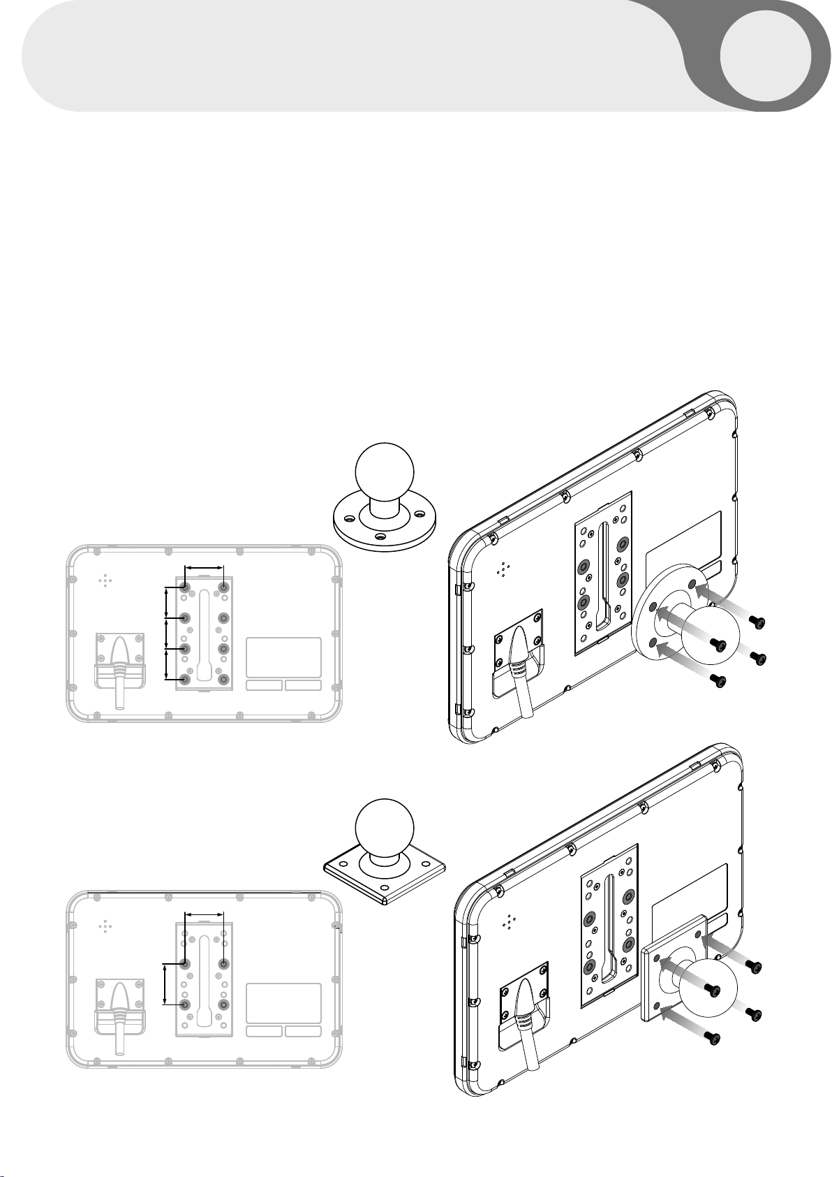
Installation of Heavy Duty Mount Bracket
17
17
The MONITOR
Please check the availability in advance, then please follow the instructions as below.
[NOTE]
• The screw type : Mount-screw type, M5 (diameter of 5mm).
• The length of screw : Max. 12mm.
• Screw thread : 0.8mm.
Please make it sure to use the proper screws in order to avoid any damage into the monitor.
can be used with different types of
Type A(option)
38mm
HEAVY DUTY MOUNTING BRACKETS.
30mm
30 30
38mm
40mm
Type B(option)
MXN10-TVI Owner's Manual
Page 18
18
SPECIFICATIONS
ITEM SPECIFICATIONS
LCD SCREEN SIZE 10.1 Inch Wide IPS Digital TFT LCD Panel
DIMENSIONS 270(W) x 174(H) x 20(D) mm
DISPLAY DIMENSIONS 216.96 X 135.6 mm
POWER INPUT DC 10V ~ 32V
POWER
CONSUMPTION
VIDEO SYSTEM
SYNC. SYSTEM Internal
BRIGHTNESS 350cd/m2
DISPLAY RESOLUTION WXGA, 1280 X (RGB) X 800
VIEWING ANGLES 178° horizontal / 178° vertical
COLOR
CONFIGURATION
DIMMER Automatic / Manual
SPEAKER IMPEDANCE Max. 8Ω / 1W
OPERATING TEMP. -20°C to + 70°C
STORAGE TEMP. -30°C to + 80°C
IMPACT RATING 5G
CAMERA CONNECTOR 4-Pin mini DIN (MXN configuration)
Max. 15W
HD-TVI (25fps, 30fps, 50fps, 60fps), AHD (25fps, 30fps)
CVBS-PAL, CVBS-NTSC
RGB Stripe
HOUSING Light Black (ABS)
ON-SCREEN
DISPLAY CONTROL
FUNCTIONS
SUPPLIED
ACCESSORIES
WEIGHT ± 850g (excluding bracket)
10.1” HD LCD MONITOR
■ Volume
■ Color
■ CAM 1/2/3, Split
■ Speed Switch
■ Distance Marker
■ Dimmer
■ Reset
Bracket -1 pce / Screw Kit -1set / Manual / Multi-cable-1 set
■ Brightness
■ Contrast Tint
■ CAM Trigger 1/2/3
■ Auto Power
■ Auto Picture Scan
■ Language
Page 19

MEMO
MXN10-TVI Owner's Manual
Page 20
OWNER’S MANUAL
PLEASE READ CAREFULLY BEFORE
USING THIS PRODUCT.
10.1” DIGITAL 3CH LCD
ALL ROUND VISION MONITOR
Model: MXN10-TVI
Design and specifications are subject to change without notice.
 Loading...