


Atmos Fusion
Thermostatic Concentric
Mixer Valve with Riser Rail
Fitting Instructions
IMPORTANT!
This Step-by-Step guide should be retained after installation.
1. INTRODUCTION
This booklet contains all the necessary fitting and
operating instructions for your MX Thermostatic bar
mixer shower.
pressure. The mixer valve must not be subjected to
water temperatures above 80˚C. This mixer valve is
also suitable for thermal storage, unvented systems
and pumped gravity systems.
Please read these instructions carefully. Read
through the whole of this book before beginning your
installation.
IMPORTANT: Before installing with a gas
instantaneous water heater, make sure it is capable
of delivering hot water at a minimum switch-on flow
The shower installation MUST be carried out by a
rate of 3 litres per minute.
suitably competent person in the sequence of this
instruction book, after reading the instructions.
At flow rates between 3 and 8 litres per minute,
the appliance must be capable of raising the water
Care taken during the installation will provide a long
temperature to a minimum of 52˚C.
and trouble free life from your shower. For the best
performance within the specified running pressure
range a minimum flow of 5 litres per minute should
be available on both inlets.
The water temperature at the inlet to the mixer valve
must remain relatively constant when flow rate
adjustments are made (refer to the water heater
operating manual to confirm compatibility with this
This mixer valve is designed to operate on higher
mixer valve).
pressure systems up to a maximum of 5 bar running
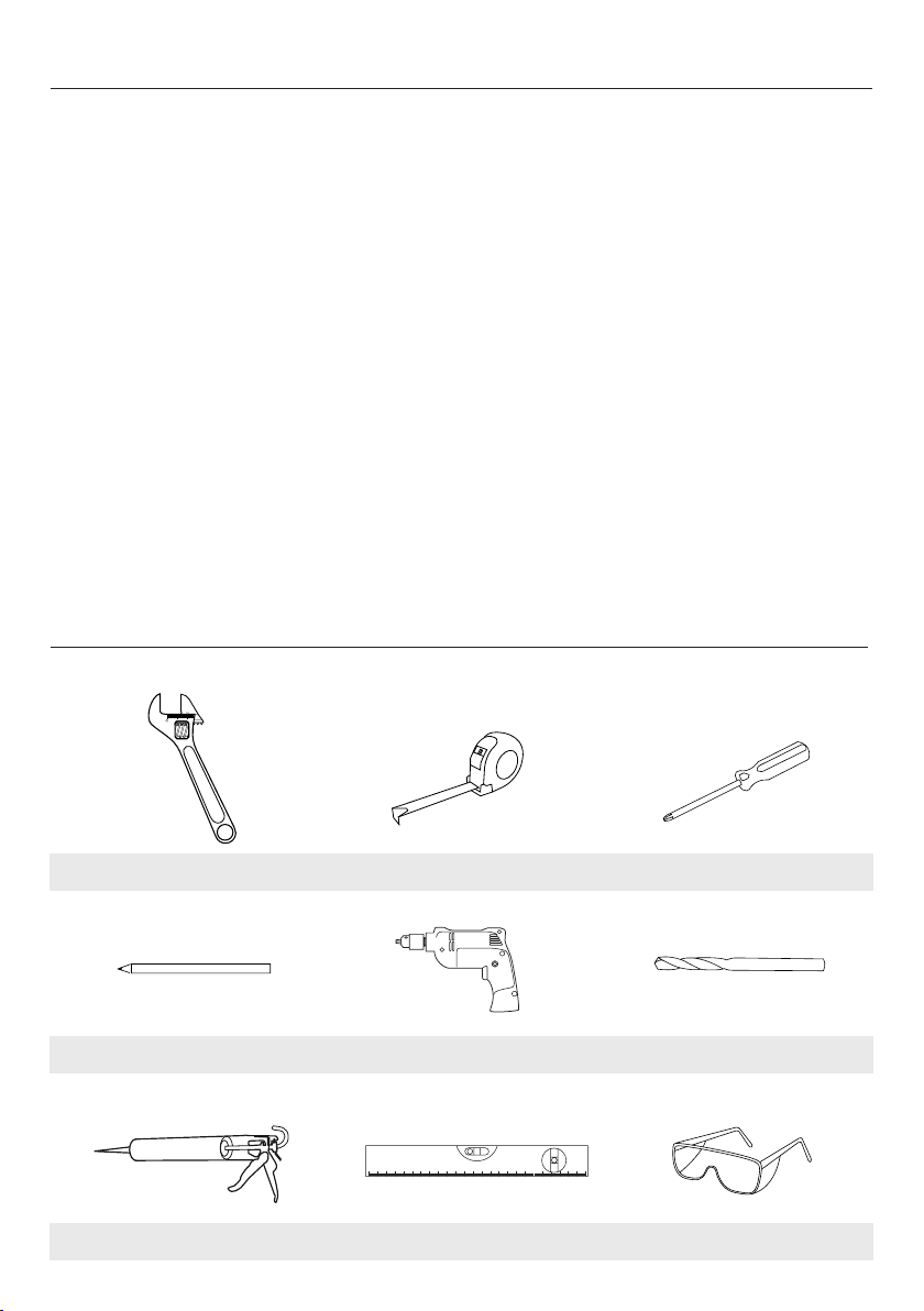
2. TOOLS REQUIRED (NOT SUPPLIED)
NOTE: Additional plumbing tools and fittings may be required.
Spanner / Wrench Tape Measure Screwdriver
HB
Pencil Power Drill Suitable Drill Bits
Silicone
Silicone Sealant Spirit Level Safety Eyewear

3. PACK CONTENTS
Please make sure ALL components are
included before starting the installation.
Description Quantity
Concentric Mixer Valve 1
6 Mode Handset 1
Curved Riser Rail 1
Riser Rail Fixing Brackets 2
Handset Height Adjuster 1
1.5m Hose + Washers 1
Concealing Plate 1
Wall Outlet 1
Nut Covers 2
Filter Washers 2
Hose Retaining Ring 1
10mm Allen Key 1
Pressure Balance Kit 1
Screw Pack (2 screws + 2 plugs) 1
Fitting Instructions 1
TMV Registration Card 1
• Riser Rail Bracket
• Riser Rail
• 6-Mode Handset
• Handset Height
Adjuster
• Concentric
Mixer Valve
• Wall Outlet
• 1.5m Shower
Hose + Washers
Concealing Plate Wall Outlet
Nut Covers Hose Retaining Ring Filter Washers
Allen Key Pressure Balance Kit Screw Pack
Fitting Instructions
IMPORTANT!
This Step-by-Step guide should be retained after installation.
Fitting Instructions and
TMV Registration Card
4. PLEASE READ THIS IMPORTANT SAFETY INFORMATION
!
!
!
!
!
!
!
!
!
!
!
!
Products manufactured by the MX Group are safe and without risk provided
they are installed, used and maintained in good working order in accordance
with our instructions and recommendations.
Layout and sizing of pipework MUST be such that when other services
are used, pressures at the shower control inlets do not fall below the
recommended minimum.
DO NOT choose a position where the shower could become frozen.
DO NOT connect this mixer valve to any form of tap or fitting not
recommended by the manufacturer.
Conveniently situated service valves in each inlet supply MUST be fitted
as an independent method of isolating the shower should maintenance or
servicing be necessary, these valves SHOULD NOT restrict the flow.
DO NOT operate the shower outside the recommended temperatures and
pressures stated in this guide.
Always test the water temperature with your hand before entering the
shower.
NOTE: As a competent person installing this shower you should ensure
that all users are very conversant in its operation.
The British Burns Association recommends 37˚C to 37.5˚C as a
comfortable bathing temperature for children. In premises covered by the
Care Standards Act 2000, the maximum mixed water outlet temperature is
41˚C.
Metal surfaces on the hot supply may become hot during operation.
Arrange to have the mixer valve regularly serviced by a suitably qualified
person.
The handset must be regularly cleaned to remove scale and debris.
5. SITE REQUIREMENTS
The installation must be in accordance with Water
Regulations Advisory Service (www.wras.co.uk).
Minimum running water pressure: 0.1 bar, but will
operate better at a minimum of 0.5 bar.
Maximum running water pressure: 5 bar. Maximum
static water pressure: 10 bar.
For your shower to perform well you should ensure
that the pressure is as specified and a minimum flow
of 5 litres per minute is available at both hot and cold
inlets.
If the water supply is fed by a gravity system then
the supply pressure should be verified to ensure the
conditions of use are appropriate for the valve.
NOTE: Water Regulations requires the handset to
be ‘constrained by a fixed or sliding attachment so
that it can only discharge water at a point not less
than 25mm above the spill over level of the relevant
bath, shower tray or other fixed appliance’. A double
check valve, or similar, MUST be fitted in the supply
pipe work to prevent back-flow.
The pressure at both the hot and cold water
supplies to the mixer valve should be the same,
and the installer should ensure that the flow is not
affected by other taps elsewhere in the house. It is
very important that for use in any mains pressure
systems an expansion tank and a pressure reducing
valve has been fitted to ensure the pressure does
not exceed 5 Bar.
This should be confirmed by the installation
engineer or competent person before installation.
WATER TEMPERATURE REQUIREMENTS
Maximum hot water temperature = 80°C,
Recommended maximum = 65°C.
Minimum hot water temperature = 55°C
Maximum cold water temperature = 20°C
TEMPERATURE ADJUSTMENT RANGE
The mixed water temperature can be adjusted from
cold through to hot. There is a safety stop preset at a
set temperature of about 38°C. Always test the water
temperature prior to using the shower.
In the event of failure of cold water system, the mixer
valve automatically reduces the flow of hot water to
prevent scalding. It will only operate again once the
flow of cold water has been resumed.
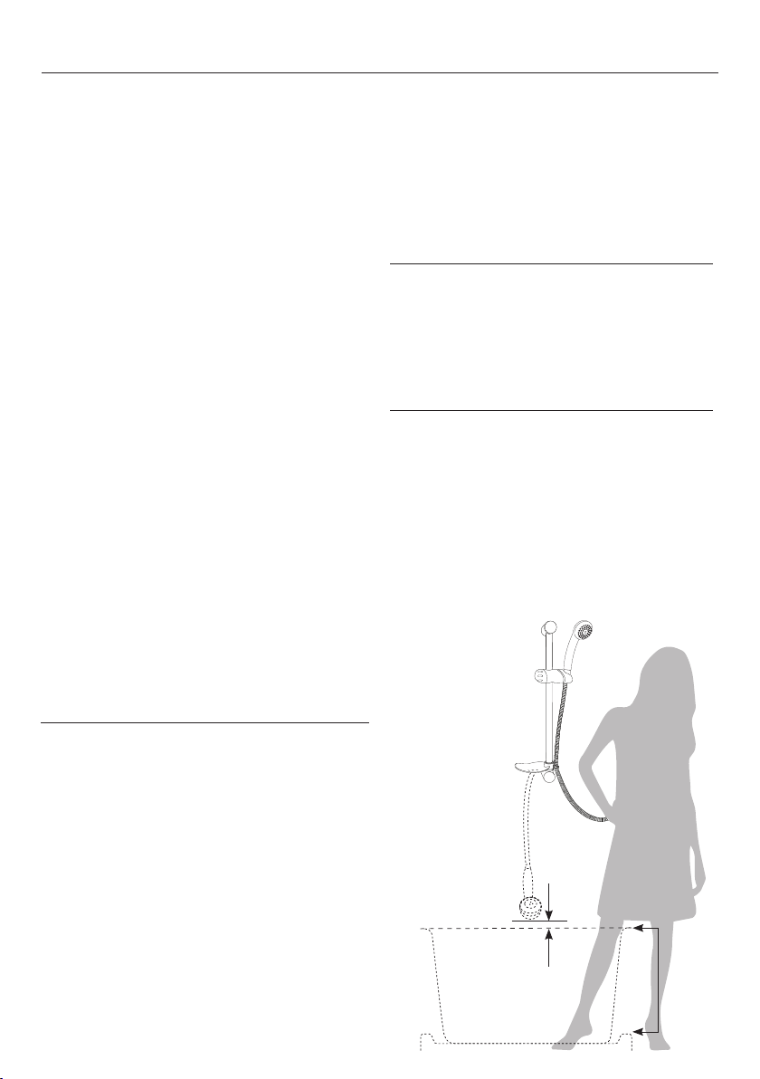
6. SITING OF THE MIXER VALVE
Position the mixer valve so that all controls can be
comfortably reached whilst using the shower.
The height of the showerhead should suit all user’s
requirements. When suspended from the hose
retaining ring, the showerhead should be a minimum
of 25mm above the spillover level of the bath or
shower tray.
NOTE: Easily accessible suitable service valves
(complying with Water Regulations Advisory
Service www.wras.co.uk), MUST be fitted as close
as practical to the valve, on the hot and cold water
supplies to the shower as an independent means
of isolating the water supplies should maintenance
or servicing be necessary. These valves should not
restrict the flow.
Height of
showerhead
to suit user’s
requirements
25mm
minimum
Spillover
level
Outline of bath or
shower tray

7. IMPORTANT INSTALLATION INFORMATION
!
!
Before proceeding with the installation check all the
components in the component list are present.
WARNING!
The shower must not be positioned where
it will be subject to freezing conditions.
The mixer valve should be fitted only after all the
pipework has been installed.
DO NOT modify or use jointing compounds on any of
the pipe fittings. DO NOT solder fittings near the mixer
valve as heat can damage the valves seals. Always
flush the system prior to installing the valve.
Before installing, make sure the mixer valve is kept
in a clean place to prevent any debris getting into the
openings while fitting the pipework.
n The mixer valve is suitable for installation on a solid
wall, a stud partition wall, dry lined wall or fixing to a
cubicle or panel.
n The water pipes should be securely attached
within the wall or panel to support the mixer valve and
prevent movement or water noise after installation.
n The mixer valve hot water inlet has a red symbol
next to the inlet and must be on the left hand side. If
the mixer valve you are fitting is with a riser rail the
outlet should point down, if the mixer valve is for an
overhead the outlet should point upwards.
n The mixer valve is designed to work at the same
hot and cold water pressures. If this is not the case a
flow controller (disc with small holes) can be fitted to
the higher pressure supply to the valve. This is best
done by testing each one to find out which gives the
best results.
n The mixer valve will be installed in such a position
that the maintenance of the TMV and its valves and
the commissioning and testing of the TMV can be
undertaken.
Before fitting the mixer valve flush out the pipework in
accordance with Water Regulations Advisory Service
(www.wras.co.uk).
8. PRESSURE BALANCING (IF SUPPLIED)
The thermostatic mixer valve is designed to work best when the feed pressures of both
hot and cold water are the same. If there is a difference in pressure it will cause the flow
of water through the valve to pulse rather than being a steady flow. This pulsing can be
reduced by putting one of the metal disks with holes into the higher pressure feed to the
valve. This restricts the flow and reduces the pulsing.
To maximise the volume of water through the valve the disk with the most holes should
be tried first. If this does not work the others should be tried until a satisfactory result
is obtained.
If the water pressures to hot and cold are the same these disks do not need
to be used.

9. FITTING THE MIXER VALVE EXPOSED OPTION
!!!
!
Hot Water
1/2” Male
IMPORTANT: Ensure that you have read through section 7. IMPORTANT INSTALLATION INFORMATION before
starting to fit the mixer valve.
1. Your thermostatic concentric mixer valve is set up
in the factory so that a shower hose can be fitted.
This means that when the valve is fitted with the hot
water coming in from the left hand side, indicated
by the red spot, the water outlet is on the bottom of
the valve and has a ½” BSP threaded male outlet
(Fig 1).
2. The supply pipework can be plumbed from above
or below but must finish at the suitable connections
which should be at 155mm centers. Connect the
15mm pipework using standard compression nut
and olives supplied with the mixer valve (Fig 2).
1
NOTE: Make sure the mixer valve is kept in a clean
place to prevent rubbish etc, getting into the openings
while fitting the pipework.
3. Complete the fitting of the pipework and the tiling
leaving the pipework as shown.Leave 155mm
(+ or - 5mm) between centers and about 30mm
out from the finished surface (Fig 3).
4. Remove the back plate from the mixer valve by
removing the retaining grub screws. Put the plate
in the centre between the feed pipes and mark the
screw positions, check this fits by holding the valve
in position. Drill plug and screw the back plate to
the wall (Fig 4).
5. Fit the two flat valve nut covers to the nuts on the
mixer valve and position the mixer valve onto the
two water feed pipes and onto the wall bracket.
To prevent moisture entering the wall put some
silicone on the underside of the mixer valve nut
covers.Carefully tighten up the compression nuts
to hold the mixer valve in place (Fig 5).
6. Make sure the mixer valve outlet is pointing in the
correct direction (with the hot feed on the left side
marked with a red indicator). Replace the locking
grub screws to hold the mixer valve onto the wall
plate.
155mm approx
2
3
4
5
CAUTION
Check there are no hidden cables or pipes before drilling holes for wall plugs.
Exercise great care when using power tools near water.
The use of a residual current device (RCD) is recommended.

10. FITTING THE MIXER VALVE CONCEALED OPTION
60mm
Minimum
IMPORTANT: Ensure that you have read through section 7. IMPORTANT INSTALLATION INFORMATION before
starting to fit the mixer valve.
1. The fitting of the mixer valve is essentially the same
as described for the exposed option, except that the
mixer valve is fixed to the wall between 50mm and
70mm below the finished surface of the shower. A
circular hole between 150mm and 173mm should
be enough to fit the mixer valve (Fig 1).
2. The supply pipework can be plumbed from above
or below but must finish at the suitable connections
which should be at 155mm centers. Connect the
15mm pipework using standard compression nut
and olives.
NOTE: You should measure the distance between the
outlets on the mixer valve you are fitting to determine
the exact distance.
1
2
3. Complete the fitting of the pipework and the tiling
leaving the pipework as shown. The wall plate
should be attached firmly between 50mm and
70mm below the finished surface. Remove the back
plate from the mixer valve by removing the retaining
screws. Put the plate in the centre between the feed
pipes and mark the screw positions, check this fits
by holding the mixer valve in position. Drill plug and
screw the back plate to the wall (Fig 2).
4. Position the mixer valve onto the two water feed
pipes and onto the wall bracket. Tighten up the
compression nuts to hold the mixer valve in place
(Fig 3).
NOTE: Make sure the mixer valve outlet is pointing
down and the hot feed is onto the left side marked
with a red indicator.
5. Replace locking screws to hold the mixer valve onto
the wall plate (Fig 4).
6. A pipe must be fitted from the outlet of the mixer
valve to the location of where you wish to position
the wall outlet. This pipe must have a ½” female
connection attached into which the wall outlet can
be fitted (Fig 5).
NOTE: Once the mixer valve and wall outlet are
fitted, prior to fitting the trim plate disc ensure all
connections are watertight. This can be done by
reconnecting the water supplies and checking the
connections when running the shower and when the
shower is off.
3
4
5
6
7. The trim plate disc is fitted by unscrewing the
handles and pushing it onto the mixer valve until
flush with the tiles (Fig 6).
8. Fit riser rail as described in the riser rail fitting
instructions. Silicone should be used to seal the
outside edge of the trim plate disc to the tiles.
NOTE: Sufficient space should be left behind the trim
plate disc to allow access to the elbows for servicing.

!!!
!
11. FITTING THE RISER RAIL AND HANDSET
!
!
1. Establish height of riser rail to suit users
requirements (Fig 1).
2. Remove end bracket cover, to explore fitting
point from upper of lower brackets (Fig 2).
3. Drill and plug the wall and fix the lower bracket
without the rail locator notch. Fit rail through
lower bracket. Place the remaining bracket on
top of the rail making sure the slot in the rail is
located into the bracket notch. Ensure the hole
position is vertically aligned and mark the wall.
Remove the rail then drill and plug the wall.
4. With the handset height adjuster on the left hand
side, fit the soap dish, then hose retaining ring
onto the bottom of the rail assembly (Fig 3).
NOTE: The soap dish in this kit is supplied
with fittings to fit both oval and round rails it is
assembled with a rubber insert for the oval rail
and must be changed to the round one which is
provided.
5. Replace the rail assembly on to the lower
bracket refit the top bracket ensure the slot or
indent in the rail is located into the bracket notch
and fix to the wall.
6. To fit the handset, connect one end of the double
interlock hose to the outlet on the mixer valve,
making sure that the sealing washer is in place.
7. Screw the remaining end of the double interlock
hose to the handset making sure the sealing
washer is in place, then locate the handset into
the handset height adjuster (Fig 4).
1
2
3
4
NOTE: It is the conical end of the double interlock
hose which grips into the handset height adjuster.
The handset will not fit in the height adjuster without
the double interlock hose attached.
Check there are no hidden cables or pipes before drilling holes for wall plugs.
Exercise great care when using power tools near water.
The use of a residual current device (RCD) is recommended.
TIPS
• A piece of insulating or masking tape applied
to the wall before marking out the fixing
holes will help stop the drill from wandering,
particularly on tiled surfaces.
CAUTION

12. COMMISSIONING AND ANNUAL MAINTENANCE TESTING
!
!
Before commissioning the following checks and tests
need to have taken place:
• All the pipe work has been flushed through before
fitting the valve and there are no leaks.
• The supply pressures and temperatures are
checked and all are in the range specified in these
instructions.
• The isolation valves and strainers are fitted and
clean of any unwanted material and do not restrict
flow.
• The valve has been fitted to the pipework with all
connections correctly tightened.
COMMISIONING PROCEDURE
1. Ensure both isolation valves are fully open. Turn the
temperature control to cold and turn the flow on.
Check the temperature is at the required
minimum.
2. Rotate the temperature controller gradually until
it reaches the preset stop. Let it flow until the hot
water has reached the valve and the temperature
has stabilized.
Check the temperature is 38˚C +/-2˚C.
This is the factory preset. If the valve does not
operate properly check and confirm that the hot
and cold water supplies are fitted to the correct
inlets.
3. Override the temperature stop button by pressing
the button and rotate to maximum being careful to
avoid scalding.
Measure the temperature.
4. The valve should then be checked to confirm the
water isolation performs correctly. Run the valve at
the 38˚C stop position.
Check the water temperature.
5. Turn off the feed of cold water using the isolation
valve.
The water flow should fall to a very low flow,
(possibly only a drip) after a few seconds.
6. Collect the water after 5 seconds and 30 seconds.
Measure the temperature – it should be below
46˚C +/- 2˚C .
7. Turn on the cold water again and it should return
after a few seconds to stabilise to 38˚C +/- 2˚C.
TEMPERATURE SETTING ADJUSTMENT
NOTE: Adjustment of the temperature settings is only
to be carried out by a competent TMV engineer as it is
a technically difficult operation in which the valve can
easily be broken.
1. Remove the handle on the temperature controller,
(noting carefully the assembly of the components).
2. Rotate the internal stops a few degrees in the
required direction.
3. Reassemble.
4. All the commissioning checks should be done
again to ensure it now meets the required
specification before using the shower.
Before use, ensure that you instruct
all users in the safe operation of the
shower as outlined in this document.

13. TROUBLESHOOTING AND FREQUENTLY ASKED QUESTIONS
If the performance of your shower deteriorates in service please follow the self help items detailed below before
seeking professional advice from the installer. If the actions below fail to restore the shower performance you
should initially contact the person or company that installed the shower.
Q. Water too HOT.
A. Six possible reasons:
1. Temperature control is not correctly
commissioned.
Adjust the temperature control - this is only a job
for a suitably qualified person.
2. Not enough cold water flowing through shower.
Turn temperature control anti-clockwise.
3. Increase in the ambient cold water temperature.
Turn temperature control anti-clockwise.
4. Cold water supply blocked.
Turn off shower and consult a competent
plumber.
5. High volume of cold water drawn off elsewhere.
Reduce the simultaneous demand from the
supply.
6. Cold water filter blocked.
Remove valve and clean filters.
Q. Water does not flow or shower pattern collapses
when another outlet is turned on.
A. Check the following:
1. Water supplies cut off
Check elsewhere in house and if necessary
contact local water company.
2. Blockage in pipework.
Turn off shower and consult a suitably
competent plumber.
3. Valve filters blocked by debris in water supply.
Remove valve and clean filters.
4. Showerhead blocked.
Clean Showerhead.
5. System not capable of supplying multiple outlet
at the same time.
Reduce simultaneous demand. Check stop/
service valves are fully open. Check if enough
water pressure.
Q. Water too COLD.
A. Nine things to check:
1. Temperature control is not correctly
commissioned.
Adjust the temperature control - this is only a job
for a suitably qualified person.
2. Not enough hot water flowing through shower.
Turn temperature control clockwise.
3. Hot and Cold supplies connected the wrong way
round.
Change water feed supply so that the hot water
is going to the feed marked with a red dot.
4. Decrease in the ambient cold water
temperature.
Turn temperature control clockwise.
5. Hot water filter blocked.
Remove valve and clean filters on the inlet.
6. Insufficient hot water supplies from the heating
system.
Make sure the hot water is available by trying a
hot water tap elsewhere in the house.
7. Hot water supply blocked or restricted.
Make sure the hot water is available by trying a
hot water tap elsewhere in the house.
8. Pressure in excess of max recommended.
Turn off shower and consult a suitably
competent plumber.
9. Combi boiler may need the correct pressure/
flow setting to start heating water when the
valve is turned on.
Contact your boiler supplier.
Q. Shower controls noisy whilst in use.
A. Running pressure in excess of maximum
recommended – fit reducing disc to outlet of valve.
Q. Shower will not shut off.
A. Flow control cartridge worn – renew flow control
cartridge.

14. THE MARLETON CROSS LTD (MX GROUP) - 5 YEAR GUARANTEE
Marleton Cross Limited (MX Group) hopes you are satisfied
with your purchase and in the unlikely event that you encounter
a problem which is caused exclusively by the MX Group
manufactured product (the “product”) we will take responsibility
on the terms set out here.
We guarantee this product, in the following terms, for a period
of 5 years, from the date of delivery, against mechanical defects
arising from faulty materials or from poor workmanship, providing
the product has been:
Installed in accordance with the fitting instructions (oral or
written), technical information supplied and/or associated
advertising;
Used strictly in accordance with all our instructions (oral or
written), associated advertising and technical data (including
product information and specification sheets) current at the time
of purchase and good working practice.
The MX Group at its discretion undertake to repair or replace
without charge, provided the product has been properly installed,
maintained and operated in accordance with the operating
instructions.
This product must not be modified, repaired or taken apart except
by a person authorised by the MX Group.
What is not covered by this guarantee
1. Any product found to be defective during this period, as the
result of misuse or damage, or the effects of scaling, will not be
covered by this guarantee.
2. Breakdown due to:
a) Use other than domestic use by you or your resident family
b) Wilful act or neglect
c) Any malfunction resulting from the incorrect use or quality
of water or incorrect setting of controls; and
d) Faulty installation.
3. Repair costs for damage caused by foreign objects of
substances or the inappropriate use of jointing compounds or
blow torches.
4. Total loss of the product due to non-availability of parts or
other reason, (MX Group will maintain stocks of spare parts for
repair for at least 5 years from end of product line to cover this
guarantee).
5. Compensations for loss of use of the product or consequential
loss of any kind.
6. Call out charges where no fault has been found with the
appliance.
7. The cost of repair or replacement of pressure relief devices,
showerheads, hoses, riser rails and/or wall bracket, tiles,
cubicles or any other parts installed at the same time.
8. The cost of routine maintenance, adjustments, overhaul
modifications or loss or damage arising there from, including
the cost of repairing damage, breakdown, malfunction caused
by corrosion, furring, pipe scaling, limescale, system debris or
frost.
9. Units purchased and installed other than in the United Kingdom.
Limitations
1. This guarantee lasts for a single continuous period of 5 years
from the date of delivery by MX Group to you the customer.
2. This guarantee is personal to the original purchaser of the
product and is not transferable.
3. Original proof of purchase(s) must be shown for any claim
under this guarantee.
4. This guarantee does not cover any products that have been
modified, altered or transformed in any way.
5. This guarantee applies to an original installation in accordance
to our fitting instructions and does not cover previously installed
products (showroom displays etc) or products that have been
moved from their original installation position for any reason.
6. This guarantee applies only to manufacturing or material
defects. It does not apply to normal wear and tear, accidental
damage, inappropriate use (including inappropriate cleaning) or
other events outside the manufacturer’s control.
7. This guarantee applies only to the product itself and any liability
on behalf of MX Group is limited to the cost of the product.
8. If a product is deemed to be of faulty manufacture MX Group
will at their discretion replace or repair the product. Any related
consequential loss or damage is excluded.
9. No claim will be accepted if a product is installed with a fault
(ours or otherwise) that would have been clearly evident before
installation.
10. We make no representations, and exclude any and all liability,
in respect of any third party products or cares supplied by way
of extensions to this guarantee.
Liability
1. Except as required or agreed by us, you will not in any
circumstances return any of the product to us, and where the
property in any of the goods returned to us has passed to you,
they will nevertheless remain your property and at your risk
unless we have agreed otherwise in writing before their return.
2. Except as stated above, we will not be liable for any direct,
consequential or other loss, damage or injury suffered or
incurred by you, and you will indemnify us fully against any
claims made by third parties, in respect of the goods or
otherwise arising from the contract.
3. Nothing contained in the contract will be treated as excluding or
restricting any liability on our part for death or personal injury
resulting from our negligence.
4. Except as stated above, and to the fullest extent permitted by
law, all conditions, warranties and representations, whether
express or implied, statutory or otherwise in relation to the
product (other than such as relate to title to the product) are
excluded.
5. You acknowledge that our prices for the goods reflect these
Terms and Conditions, and accordingly that you accept the
above limitations on and exclusions of liability in exchange for
those prices.
6. When providing information to MX-Group you understand
that you are doing this subject to our terms and other policies
(including data protection) we have in place from time to time,
copies of which are available on our website www.mx-group.
com or on request as per the MX Group contact details given
herein.
7. This guarantee does not affect your statutory rights.

15. SERVICE POLICY
In the event of you needing to contact the MX Group Customer Service Department, the following procedure
should be followed:
1. Before telephoning on 0845 505 2211 the MX Group
Customer Service Department you should ensure
you have the model number (printed on the valve),
the date and proof of purchase, your contact details
and the postcode where the unit is installed.
2. The MX Group Customer Service Department will
be able to tell you whether the fault can be simply
rectified by the provision of a replacement part
or arrange an on site visit by a Qualified Service
Engineer.
3. If a service call is required it will be booked and the
date of the call confirmed. You or a representative
(over the age of 18 years) must be present during
the entire engineers visit. The engineer will not
be able to repair or replace or advise on parts or
products not supplied by MX.
4. In the event of a service call aborted by you or
where a call has been booked under our guarantee
but failure is not related to the product supplied by
MX then a charge will be made.
5. If the product is no longer covered by the guarantee,
a charge will be made for the site visit and for any
parts supplied.
6. Service charges are based on the account being
settled when work is complete, the engineer will
then request payment. If this is not made to the
service engineer or settled within ten working days,
an administration charge will be added.
16. SPARE PARTS
In the event that parts or maintenance is needed outside the guarantee MX will endeavour to help with
this. Spare parts codes are given in the fitting instructions. By calling the Customer Service Department
on 0845 505 2211 with the part number, they will be able to quote you to supply these parts, usually via our
spares distributor.

NOTES

NOTES

Customer Care Department
Telephone: 0845 505 2211
9.00 am - 5.00 pm Monday to Friday
6751G KL/JULY2016
Marleton Cross Limited Trading as The MX Group
Alpha Close, Delta Drive, Tewkesbury Industrial Estate, Tewkesbury, Gloucestershire GL20 8JF
Tel: 01684 293311 Fax: 01684 293900 Email: sales@mx-group.com www.mx-group.com
CUSTOMER CARE: 0845 5052211
TRADE DESCRIPTIONS ACT
Variations in terms of colour finish, materials and all other aspects of appearance may occur on occasions, either
through non-availability of materials or due to our policy of continuing technical improvement. Therefore the Company
reserves the right to change specification or withdraw products from this list without prior notice being given.
 Loading...