

DATA BULLETIN
CMX018
UHF FM/FSK Receiver
Features Applications
•
Double Conversion Super-Heterodyne
Receiver and FM/FSK Demodulator
•
LNA with Switched Gain
•
High Performance UHF Down-Converter
Stage with Integrated VCO
•
2.7V Operation
•
Zero-Power Mode (<10µA)
•
Temperature Compensated RSSI
•
28-Pin SSOP Package
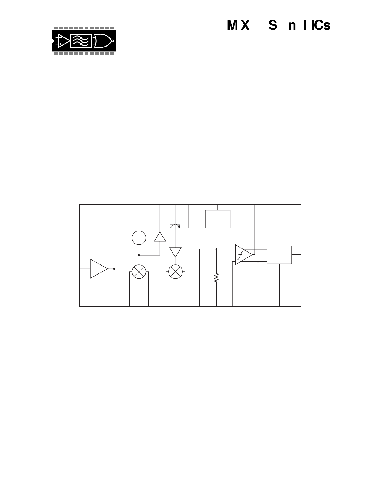
GAINSEL
ST
1DOWN
CONVERTER
TAN K
VCO
BUFFERED
OSCILLATOR
OUTPUT
OSCOUT OSCBA OSCEM
CONVERTER
ND
2DOWN
•
High Performance Analog/Digital
Radio Links (860-965MHz)
•
General ISM 915MHz Band
•
Analog/Digital Cordless Phones
•
Spread Spectrum Receivers
•
Analog FM Receivers
•
Handheld Data Terminals
•
SO-HO Wireless Data Links
ENABLE
BANDGAP
& BIAS
CONTROL
IF LIMITING
AMPLIFIER
ADVANCE INFORMATION
RSSI
LNAIN
FM/FSK
DISCRIMINATOR
LNA
LNADEC
50W
MIX1IN
MIX1OUT
100W100W50W 430W
MIX2OUT
MIX2IN
LIMIN
LIMDEC1
430W
LIMOUT QUADINLIMDEC2LNAOUT
50W
DETOUT
The CMX018 is a single chip UHF FM/FSK double-conversion super-heterodyne receiver. It combines a dual
gain mode Low Noise Amplifier (LNA), two down-converters (including integrated oscillators), limiting
amplifier, RSSI, FM/FSK demodulator and zero-power mode control.
The CMX018 can be used in conjunction with the CMX017, an integrated FM/FSK modulator and transmitter,
to implement a complete UHF radio link.
The CMX018 operates from a 2.7V to 3.3V power supply and is available in the following package style:
28-pin SSOP (CMX018D6).
1999 MX-COM, Inc. www.mxcom.com Tel: 800 638 5577 336 744 5050 Fax: 336 744 5054 Doc. # 20480194.003
4800 Bethania Station Road, Winston-Salem, NC 27105-1201 USA All trademarks and service marks are held by their respective companies.

UHF FM/FSK Receiver 2 CMX018 Advance Information
CONTENTS
Section Page
1 Internal Block Diagram..................................................................................................3
2 Signal List.......................................................................................................................4
3 External Components....................................................................................................5
4 General Description.......................................................................................................6
4.1 Low Noise Amplifier............................................................................................................. 6
4.2 First Down-Converter .......................................................................................................... 6
4.3 Second Down-Converter ..................................................................................................... 6
4.4 Limiting Amplifier and RSSI................................................................................................. 6
4.5 FM/FSK Demodulator.......................................................................................................... 6
4.6 Zero-Power Mode................................................................................................................ 6
5 Application Notes ..........................................................................................................7
5.1 General................................................................................................................................ 7
6 Performance Specification..........................................................................................10
6.1 Electrical Performance ...................................................................................................... 10
6.1.1 Absolute Maximum Ratings.................................................................................................. 10
6.1.2 Operating Limits...................................................................................................................10
6.1.3 Operating Characteristics.....................................................................................................11
6.2 Packaging.......................................................................................................................... 13
6.3 Handling Precautions ........................................................................................................ 13
MX-COM, Inc. reserves the right to change specifications at any time and without change.
1999 MX-COM, Inc. www.mxcom.com Tel: 800 638 5577 336 744 5050 Fax: 336 744 5054 Doc. # 20480194.003
4800 Bethania Station Road, Winston-Salem, NC 27105-1201 USA All trademarks and service marks are held by their respective companies.
UHF FM/FSK Receiver 3 CMX018 Advance Information
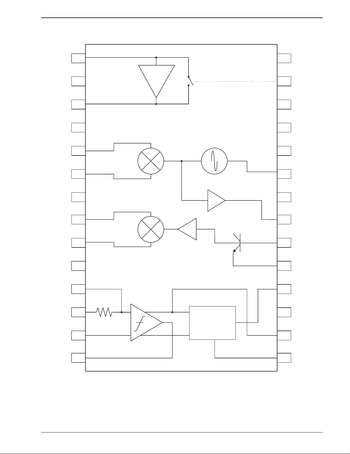
1
Internal Block Diagram
LNAIN
GND
LNAOUT
GND
MIX1IN
MIX1OUT
GND
MIX2IN
1
28
ENABLE
LNA
27
26
25
24
23
22
GAINSEL
LNADEC
V 1
CC
GND
TANK
V 2
CC
2
3
4
ST
1DOWN
5
CONVERTER
6
7
BUFFERED
VCO OUTPUT
21
8
OSCOUT
MIX2OUT
GND
LIMIN
LIMDEC1
LIMDEC2
RSSI
10
11
12
13
14
20
9
ND
2DOWN
OSCBA
CONVERTER
19
OSCEM
18
IF LIMITING
DETOUT
AMPLIFIER
430W
17
V 3
CC
FM/FSK
DEMODULATOR
16
LIMOUT
15
QUADIN
Figure 1: Internal Block Diagram
1999 MX-COM, Inc. www.mxcom.com Tel: 800 638 5577 336 744 5050 Fax: 336 744 5054 Doc. # 20480194.003
4800 Bethania Station Road, Winston-Salem, NC 27105-1201 USA All trademarks and service marks are held by their respective companies.
UHF FM/FSK Receiver 4 CMX018 Advance Information
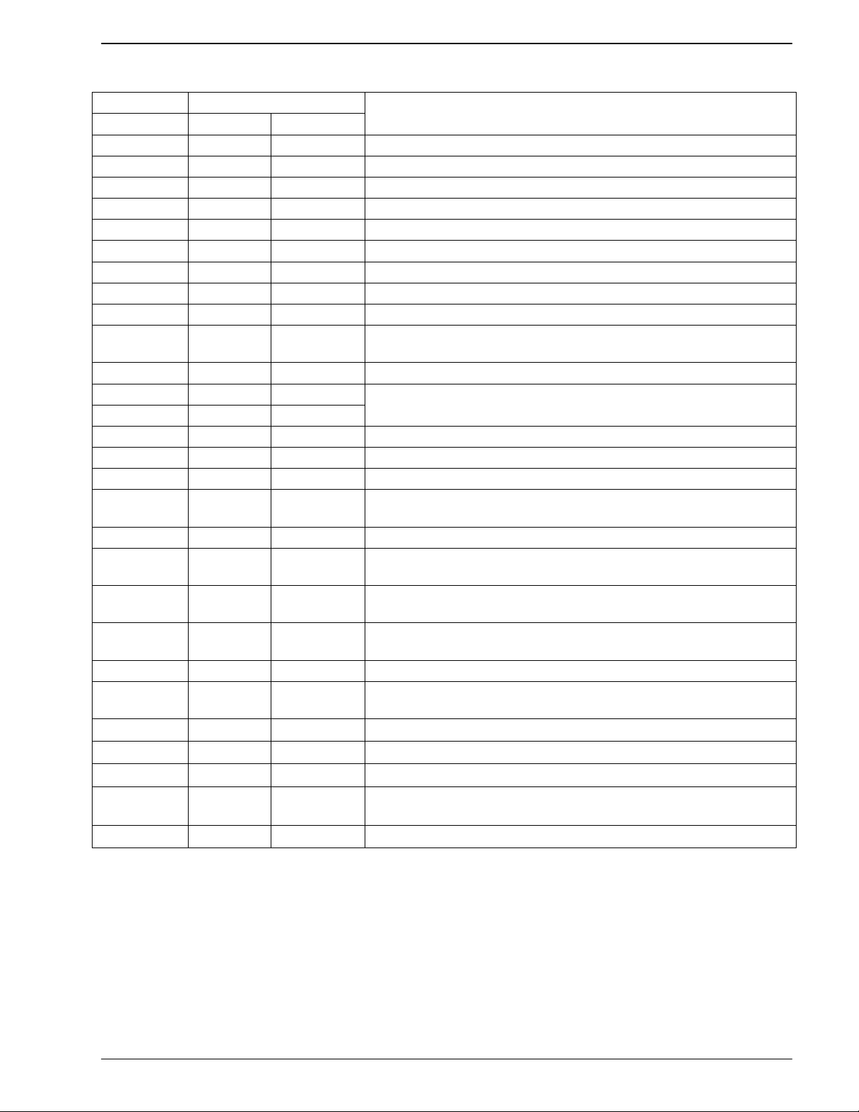
2 Signal List
Pin No. Signal
Description
Package D6 Name Type
1 LNAIN input LNA RF Input
2 GND ground LNA Ground connection
3 LNAOUT output LNA RF Output
4 GND ground LNA Ground connection
5 MIX1IN input RF Input to the First Down-Converter
6 MIX1OUT output IF Output from the First Down-Converter
7 GND ground First Down-Converter Ground connection
8 MIX2IN input RF Input to the Second Down-Converter
9 MIX2OUT output IF Output from the Second Down-Converter
10 GND ground Second Down-Converter, Limiting Amplifier, RSSI, and
Demodulator stages - Ground connection
11 LIMIN input Input to the Limiting Amplifier
12 LIMDEC1 input
13 LIMDEC2 input
External Decoupling capacitors – one required at each limiting
Amplifier Inputs
14 RSSI output Receive Signal Strength Indicator output
15 QUADIN input Quadrature input to the FM Demodulator
16 LIMOUT output Output from the Limiting Amplifier
17 Vcc3 power Power supply to the Second Down-Converter, Limiting Amplifier,
RSSI and Demodulator stages – nominally 3.0V
18 DETOUT output Output of the FM/FSK Quadrature Demodulator
19 OSCEM
Emitter connection to the Second Down-Converter Local Oscillator
transistor
20 OSCBA Base connection to the Second Down-Converter Local Oscillator
transistor
21 OSCOUT output
Buffered Local Oscillator (Open-Collector) output from the First
Down-Converter
22 VCC2 power First Down-Converter 3V Supply
23 TANK input
First Down-Converter Local Oscillator (VCO) TANK/Resonator
connection
24 GND ground First Down-Converter VCO Ground connection
25 VCC1 power LNA Power Supply – nominally 3.0V
26 LNADEC External LNA bias decoupling capacitor
27 GAINSEL CMOS input LNA Gain control logic input. A logic ‘0’ provides a typical power
gain of 16dB and a logic ‘1’ provides an attenuation of 6dB
28 ENABLE CMOS input Zero-Power logic control. A logic ‘0’ powers down the device.
Table 1: Signal List
1999 MX-COM, Inc. www.mxcom.com Tel: 800 638 5577 336 744 5050 Fax: 336 744 5054 Doc. # 20480194.003
4800 Bethania Station Road, Winston-Salem, NC 27105-1201 USA All trademarks and service marks are held by their respective companies.
 Loading...