

MXCHIP MiCOKit-3239 Hardware Manual
Shanghai MXCHIP Information Technology Co., Ltd.
Address:Floor 9, Building 5, No. 2145, Putuo District, Shanghai (200333) Tele ph on e:021-52709556 Website:http://mxchip.com/
MiCOKit-3239 Development Kit Hardware Manual
Abstract
MiCOKit from MXCHIP is one development kit based on MiCO. It could be used for the development of smart
devices and the demos. This development kit provides one easy solution for developing smart devices. And it’s
convenient in achieving the applications of users.
More Help
Please login the website: http://mxchip.com/ to get Mxchip's latest product information.
Hardware Engineering Department Working Group
Jing Minhua
Track Number: RM0087EN
MXCHIP Co., Ltd
Version: 1.1
July 2017
Category: Reference Manual
Open
MiCOKit-3239 Development Kit Hardware Manual [Page 1]
RM0088EN
Version Record
Date
Version
Update content
6-29-2017
V1.0
Initial version.
7-11-2017
V1.1
Add section 3: description of extension board
MiCOKit-3239 Development Kit Hardware Manual [Page 2]
RM0088EN
Catalog
MiCOKit-3239 Development Kit Hardware Manual ...................................................................................................... 1
Version Record .................................................................................................................................................................... 1
1. Overview ...................................................................................................................................................................... 4
Hardware .......................................................................................................................................................... 4 1.1
Software ........................................................................................................................................................... 5 1.2
Support for developers ..................................................................................................................................... 5 1.3
2. Main board .................................................................................................................................................................. 6
Power ............................................................................................................................................................... 6 2.1
USB to UART .................................................................................................................................................. 7 2.2
Wi-Fi module ................................................................................................................................................... 8 2.3
LED lights ........................................................................................................................................................ 9 2.4
Working mode ................................................................................................................................................ 10
2.5
Buttons ........................................................................................................................................................... 10 2.6
JTAG debug connector................................................................................................................................... 10 2.7
Arduino connector ......................................................................................................................................... 11 2.8
Schematics ..................................................................................................................................................... 12 2.9
PCB ................................................................................................................................................................ 13 2.10
3. Extension board ........................................................................................................................................................ 15
OLED screen.................................................................................................................................................. 16 3.1
RGB LED ...................................................................................................................................................... 16 3.2
Environment sensor (optional) ....................................................................................................................... 17 3.3
Nine axis motion sensor (optional) ................................................................................................................ 18 3.4
Range& solar sensor ...................................................................................................................................... 18 3.5
Temperature& humidity sensor ...................................................................................................................... 19
3.6
Infrared reflection switch ............................................................................................................................... 20 3.7
Solar sensor .................................................................................................................................................... 20 3.8
Mini-type DC motor ...................................................................................................................................... 21 3.9
Standard Arduino connector .......................................................................................................................... 21 3.10
Arduino sensor connector .............................................................................................................................. 22 3.11
UART connector ............................................................................................................................................ 22 3.12
Schematic of extension board ........................................................................................................................ 23 3.13

MiCOKit-3239 Development Kit Hardware Manual [Page 3]
RM0088EN
Picture Catalog
Figure 1 MiCOKit Development Board .............................................................................................................. 4
Figure 2 MiCOKit-3239 Main Board .................................................................................................................. 6
Figure 3 The Circuit of Power Supply ................................................................................................................. 7
Figure 4 USB to UART Circuit ........................................................................................................................... 8
Figure 5 Serial Installing ..................................................................................................................................... 8
Figure 6 EMW3239 ............................................................................................................................................. 9
Figure 7 LED Circuit ........................................................................................................................................... 9
Figure 8 Buttons ................................................................................................................................................ 10
Figure 9 JTAG Connector ................................................................................................................................... 11
Figure 10 Arduino Connector ............................................................................................................................. 11
Figure 11 MiCOKit Extender Board .................................................................................................................. 15
Figure 12 OLED Screen Circuit ........................................................................................................................ 16
Figure 13 RGB Driver Circuit ........................................................................................................................... 17
Figure 14 P9813 Driver Timer ........................................................................................................................... 17
Figure 15 Environment Sensor Circuit .............................................................................................................. 17
Figure 16 Nine-axis Motion Sensor Circuit ....................................................................................................... 18
Figure 17 APPLE CP Circuit ............................................................................................................................. 18
Figure 18 Range& Solar Sensor Circuit ............................................................................................................ 19
Figure 19 Temperature& Humidity Sensor Circuit ............................................................................................ 19
Figure 20 DHT11 Timing .................................................................................................................................. 20
Figure 21 Infrared Reflection Sensor Circuit..................................................................................................... 20
Figure 22 Solar Sensor Circuit .......................................................................................................................... 21
Figure 23 DC Motor Circuit .............................................................................................................................. 21
Figure 24 Extender Board Arduino Circuit ........................................................................................................ 22
Figure 25 Arduino Sensor Connector Circuit .................................................................................................... 22
Figure 26 UART Connector Circuit ................................................................................................................... 22
Figure 27 Schematic of extension board ............................................................................................................ 23
Table Catalog
Table 1 Working Mode ...................................................................................................................................... 10
MiCOKit-3239 Development Kit Hardware Manual [Page 4]
RM0088EN
1. Overview
MiCOKit from MXCHIP is one development kit based on MiCO. It could be used for the development of smart
devices and the demos. This development kit provides one easy solution for developing smart devices. And it’s
convenient in achieving the applications of users.
MiCOKit features:
Based on MiCO, high efficiency, safe and easy to use;
Sufficient peripherals;
Various Demos and perfect MiCOKit SDK are available;
The kits include hardware, software and community parts with MiCOKit development board and the demos about
how to connect to cloud platform to achieve the controlling by mobile phone.
FogCloud service is prepared;
Interaction with phone and PC;
Interface for main third cloud platform: Aliyun, Microsoft, Amazon, IBM, Wechat, AirKiss, Ayla,
FogCloud, GizWits, Haier U+, Arrayent and so on;
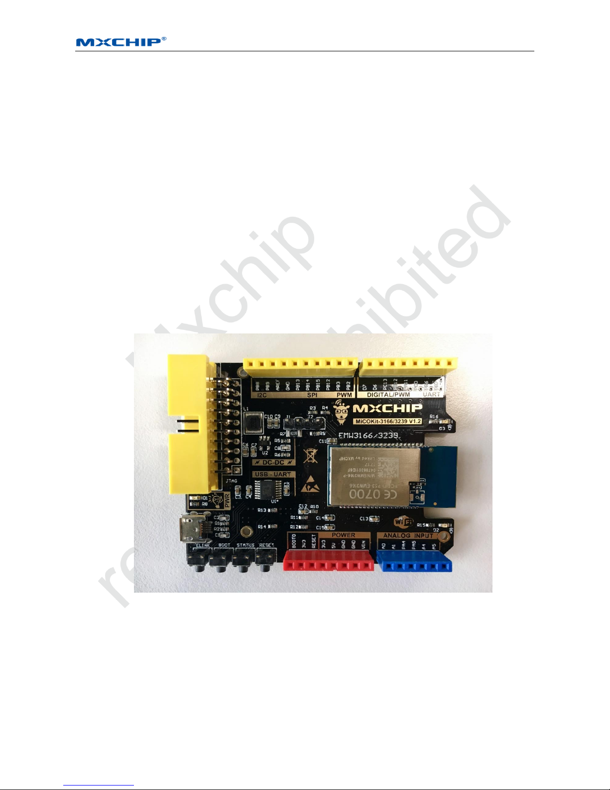
Figure 1 MiCOKit Development Board
Hardware 1.1
Double plate cascade structure is applied in MiCOKit. It includes two parts: one is the standard Arduino board with
MCU and wifi core, and the other one is the Arduino extender board. The main board has various types, while the
extender board is one standard board which can fit in different main board. The extender board equips with RGB
LED, various sensors and some debug .pins which can be used to achieve quick developments.

MiCOKit-3239 Development Kit Hardware Manual [Page 5]
RM0088EN
Part number: MiCOKit-3239 (including both baseboard and extension board)
MiCOKit-base-3239 (baseboard only)
Software 1.2
MiCOKit is based on MiCO. Developers can easily develop their own product by using supplied SDK which takes
the features of IoT developing.
One completed cloud platform service is already available. Developers could see the sensor data and control the
devices on board by using FogCloud service and APP “MICO enjoy” in order to achieve the interaction between
mobile phone and MiCOKit.
Support for developers 1.3
One account of MiCO developers’ community and the privilege for developing support are provided by using
MiCOKit. It includes the necessary developing resources, SDK, MiCO community and the information about how
to connect to other cloud platforms by using interfaces in software frame provided by MXCHIP.
MiCO developers’ community: www.MiCO.io.
MiCOKit-3239 Development Kit Hardware Manual [Page 6]
RM0088EN
2. Main board
MiCOKit-3239 applies the Wi-Fi module with Arduino standard, main components:
EMW3239 from MXCHIP;
2Mbyte build-in SPI flash within EMW3239;
Demos about solution of MiCO-Cloud-APP for secondary development;
USB to UART serial port for debugging;
3 indicator LED of working status;
Power supply: Micro-USB 5V with one DC-DC onboard 5V-3.3V.
JTAG/SWD debug connector;
Pins for Arduino extender board;
The functions of the pins on MiCOKit main board could be distinguished by color. Yellow is for digital signal pins,
blue is for analogue signal pins and red is for power supply.
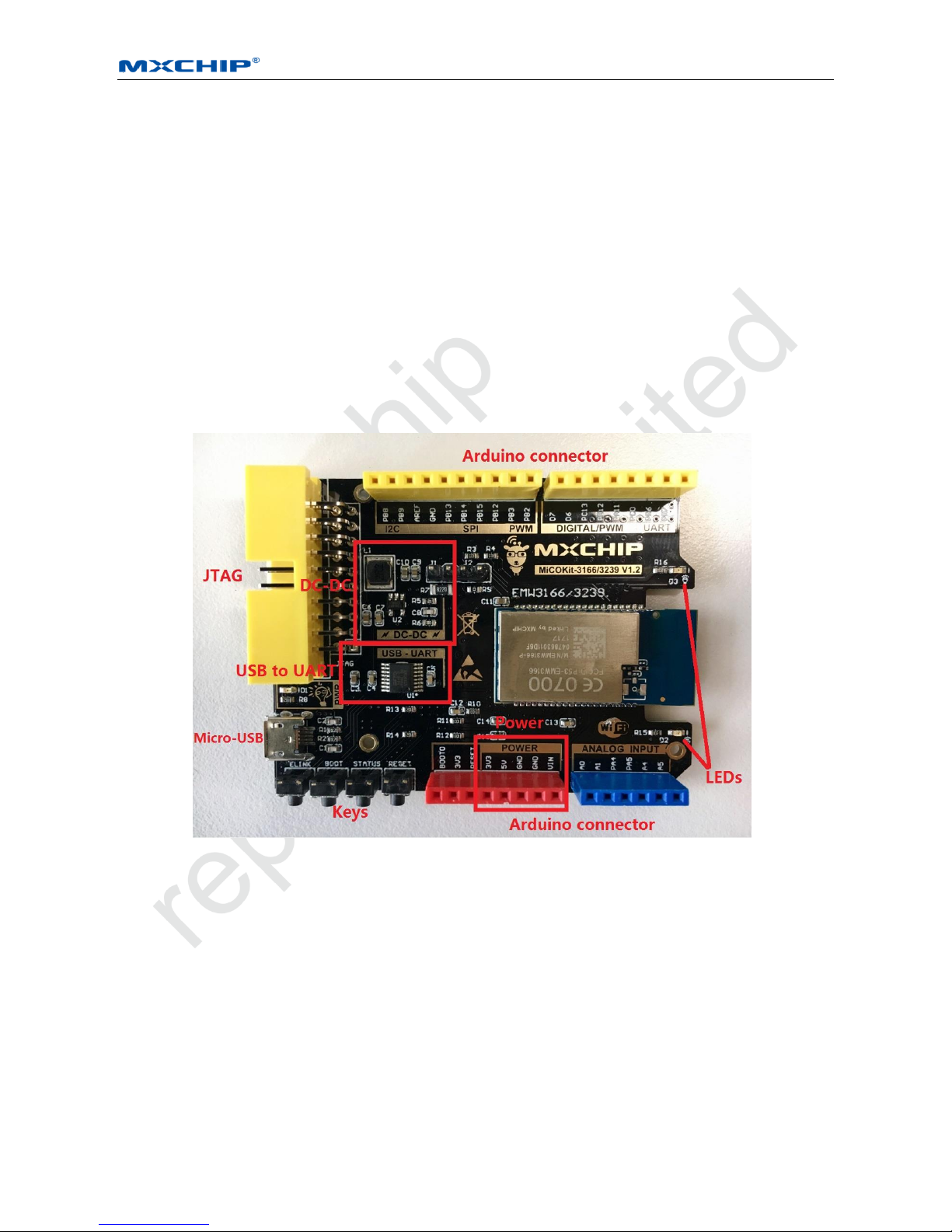
Figure 2 MiCOKit-3239 Main Board
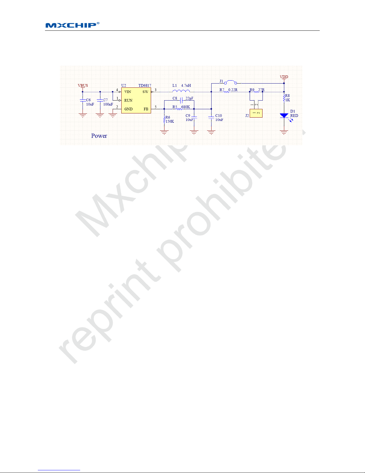
Power 2.1
MiCOKit uses USB as the power supply and serial communication, and one high efficient DC-DC (TD6817).
TD6817 is one monolithic synchronous buck regulator with high efficiency (96%) and constant frequency (1.5MHz).
The output voltage has three types: changeable, stable 1.5V and 1.8V. The maximum output current is 2A, while the
static loss is just 20uA. The output voltage 2.5V-5.5V is suitable for the power supply of single lithium battery. The
switch frequency is set as inner 1.5MHz which is convenient for small SMT inductor and capacitor. It has the
function of over-temperature protection.
MiCOKit-3239 Development Kit Hardware Manual [Page 7]
RM0088EN
The circuit shows like figure 3. The power light D1 lights when power supply works. R7 and J1 are designed for
power consumption testing.
Figure 3 The Circuit of Power Supply
USB to UART 2.2
The part USB to UART with FT230X on MiCOKit board is applied for debugging.
The main function:
Handshake signal, modem connector signal, hardware and Xon/Xoff data flow control;
UART: 7/8 Bit data bits, 1/2 stop bits, odd/even parity;
Rate: 300=>3M(TTL), 512Byte buffer;
I/O voltage: 3.3V-5V;
Compatible with USB 2.0;
Driver: Windows 8 32/64-bit, Windows 7 32/64-bit, Windows Vista/Vista 64-bit, Windows XP/XP 64-bit,
Server 2003, XP and Server 2008, Windows XP Embedded, Windows CE 4.2, 5.0 and 6.0, Mac OS-X, Linux
3.2 and greater, Android and so on.
Packaged as SSOP16 and QFN16 with lead free.
The circuit for this part:
 Loading...