

MWM Acteon, Acteon 4.12TCE, Acteon 6.12TCE Workshop Manual
Workshop Manual
Workshop Manual
MWM- Motores
Assistência ao Cliente / Asistencia al Cliente / Customer Assistance
Av.das Nações Unidas, 22.002
CEP- 04795-915 - São Paulo- SP - Brasil
Internet:
e-mail
Fone:
Fax:
(DDG):
9.612.0.006.7160 - 11/06
Impresso no Brasil
International
www.mwm-international.com.br
: mwm@mwm.com.br
+55(11) 3882-3200
+55(11) 3882-3574
0800 0110229

Presentation
1 - 1
9.612.0.006.7160 - 05/04
Presentation
Introduction....................................................................................................................................... 1-2
How to Use this W orkshop Manual .................................................................................................. 1-2
Important Safety Remarks ................................................................................................................ 1-3
General Instructions ......................................................................................................................... 1-4
Cleaning General Instructions ......................................................................................................... 1-5
Engine Serial Number Identification and Location......................................................................... 1-6
Cylinder Numeration......................................................................................................................... 1-7

1 - 2
Presentation
9.612.0.006.7160 - 05/04
Introduction
This manual contains complete information and specification to assembly and disassembly MWM Acteon engines
and all components manufactured by MWM Motores Diesel Ltda.
Read and follow all saf ety instructions. Consult the item ATTENTION in the Safety Gener al Instructions, in the next
section.
The repairing procedures, described in this manual, consider that the engine is positioned on an appropriate stand.
Some of the assembly and disassembly procedures require special tools.
Make sure that the correct tools are used according indicated in the procedures.
The assembly and disassembly specifications and information presented in this manual are the ones which is
effective in the moment of its print. MWM Motores Diesel Ltda. reserves the right of making any change, at any
moment. MWM Motores Diesel Ltda. reserves the right of doing changes in the product at any moment without this
to incur in any further obligation. In case of any difference in the engine or information of this manual, contact an
MWM Authorized Distributor or the f actory .
The components used in MWM engines production are produced with last generation technology components and
with high level quality standards . When parts changes are necessary, it is recommended to use only MWM gen uine
spare parts. These parts can be identified by the following marks.
How to Use this Manual
T o create this Manual it has been tak en as base a generic MWM Acteon engine, which operations and maintenance
procedures are the same for all models of this series. The illustrations therefore, could differ from application to
application.
In this Manual, all references to the components of the engine are divided in 17 specific sections. For your convenience,
the organization of the Manual is consistent with MWM Service Bulletins.
Content of the Manual
The Manual contains an index that can be used as a quick reference to access each section.
Content of the Sections
Each section contains the following information:
• Page of index in the beginning of each section to help f or the f ast location of the desired inf ormation.
• General information about the operation of the component and the explanation of their main changes.
• Component disassembly , cleaning, inspection and dimension instructions.
Remissive Index
In the end of the manual there is a remissive index to help the location of specific information.
Information on Metric System
All dimensions are expressed in the International Metric System (I.S.).

Presentation
1 - 3
9.612.0.006.7160 - 05/04
Important Safety Remarks
Carefully read all safety procedures and remarks before performing any repair in the engine. The following list presents
the general cautions that must be followed to guarantee your personal safety. Special safety measures can be
presented with the procedures, if necessary .
• Make sure that the work area around the engine is dry, well lightened, ventilated, organized; without tools and
loosened parts, ignition sources and dangerous substances. Check f or dangerous conditions can happen and
avoid them.
• Always use individual protection equipments (safety eyeglasses, gloves, shoes, etc.) while you are working.
• Remember that parts in movement can cause cuts, mutilation and strangling.
• Do not use loosen or ripped clothes. Remove jewellery and watches before working.
• Disconnect the battery (negative cable first) and discharge the capacitors before beginning the repairs.
• In case the repair is being made in the vehicle, disconnect the starter motor to avoid an accidental start of the
engine. In case of industrial engines, place a “Do Not Operate” warning in the operator compartment or on the
controls.
• T o man ually rotate the engine, use ONLY the recommended procedures. Never try to rotate the crankshaft with
the fan. This practice can cause serious personal injuries or damages to the fan blades , causing the premature
failure of the component.
• If the engine was in operation and the cooling fluid is hot, leave the engine to cold down before slowly open the
cover of the reservoir to relief the pressure of the cooling system.
• Do not work with materials that are lifted by jacks or cranes.
Always use correct blocks, stands or br ack ets to position the engine before perf orming any repair .
Relief the pressure of the pneumatic (brakes), lubrication and cooling systems before removing or disconnect
any piping, connections or other elements. Pa y attention to the pressure existence before to disconnect an y item
of a pressurized system. Do not check pressure leakages with the hand. Oil or fuel at high pressure can cause
injuries.
• T o av oid injuries, use a crane, or ask for help to lift components which w eight more than 20 kg. Mak e sure that all
lift equipments as chains, hooks or belts are in good conditions and have the correct load capacity. Make sure
that hooks are correctly positioned. Alw a ys use an extension when necessary. The lift hooks must not receive
side loads.
• Never lea ve the engine operating in a closed and non v entilated area. The engine e xhaust gases are harmful to
health.
• The MWM coolant has alkaline substances. Avoid the contact with the eyes . Avoid the prolonged or repetitiv e
contact with the skin. Do not ingest. In case of contact with the skin, wash immediately with water and soap. In
case of contact with the eyes, abundantly wash with water for, at least 15 minutes. CALL MEDICAL HELP
IMMEDIA TELY . KEEP A W AY FROM THE REA CH OF THE CHILDREN AND ANIMALS .
Attention
• Incorrect procedures and lack of care can cause burns, cuts, mutilation, asphyxia or other
injuries and even death.

1 - 4
Presentation
9.612.0.006.7160 - 05/04
• Cleaning solutions and solvents are inflammable materials that must be handled with a lot of care. Follow the
manufacturer instructions to use these products. KEEP AW A Y FROM THE REACH OF CHILDREN AND ANIMALS.
• To avoid burns, pay attention to hot spots on engines that have just been stopped and to hot piping and
compartments.
• Always use tools in good conditions. Make sure that you know how to handle the tools before beginning any
repair. Use ONLY genuine MWM spare parts.
• Some international public health institutions prove that used lubricant oil can be cancerous and contaminates the
human reproducer system. A void inhaling v apours, ingesting or keeping prolonged contact with these substances.
• People with pacemaker m ust av oid standing close to the engine electronic injection system.
General Instructions
This engine has been manufactured with the most advanced technology; nev ertheless, it was designed to be repaired
using regular techniques complemented by quality standards.
• Use good quality fuel, free of water and impurities.
• Use only recommended lubricant oil.
• In case of any irregularity seek for a dealer or authorized service of the vehicle / equipment manufacturer or
MWM. A v oid that outsiders mak e an y service in the engine, because this cancels the warranty.
• To use a parallel battery to start de engine, the amperages of both batteries must be the same to avoid tension
peaks. The standard procedure is alw ays first to connect the cable on the negativ e pole and later on the positive
pole. Take care to do not invert the poles.
• The inadequate removal of the battery cables may cause the loss of data from ECM, erasing the saved errors
from the last start of the engine. It can also cause tension peak, provoking ECM to break do wn.

Presentation
1 - 5
9.612.0.006.7160 - 05/04
MWM Motores Diesel Ltda.
Service Department
Av . das Nações Unidas , 22.002 - Santo Amaro
Zip Code: 04795-915 - São P aulo - SP - Brazil
Phone: (55) (11) 3882-3513 / 3305
Fax: (55) (11) 3882-3574
DDG: 0800-110 229
Site: www .mwm.com.br
E-mail: servicos@mwm.com.br
Cleaning General Instructions
Cleaning with Acids and Solvents
Several solv ents and acid substances can be used to clean the parts of the engine.
MWM Motores Diesel Ltda. does not recommend any specific substance. Always follow the instructions of
the manufacturer of the product.
Remove all gaskets, sealing rings, and with a brush of steel or rasper, the sludge deposits, carbon, etc., before
placing the parts in the cleaning tank. Be careful to do not damage the surfaces of the sealing elements seats.
Flush all parts with hot water after cleaning. Completely dry them with compressed air. Remove water from scre w
holes and from lubrication inner grooves.
In case the parts are not to be used soon after the cleaning, dip them in an appropriate anti-oxidation compound. That
compound must be removed of the parts before installation in the engine.
The following parts cannot be cleaned with vapour:
1 . Electric and electronics components;
2 . Electric harness;
3 . Fuel injectors;
4 . High pressure pump;
5 . Belts, pipes and hoses;
6 . Bearings.
1 - 6
Presentation
9.612.0.006.7160 - 05/04
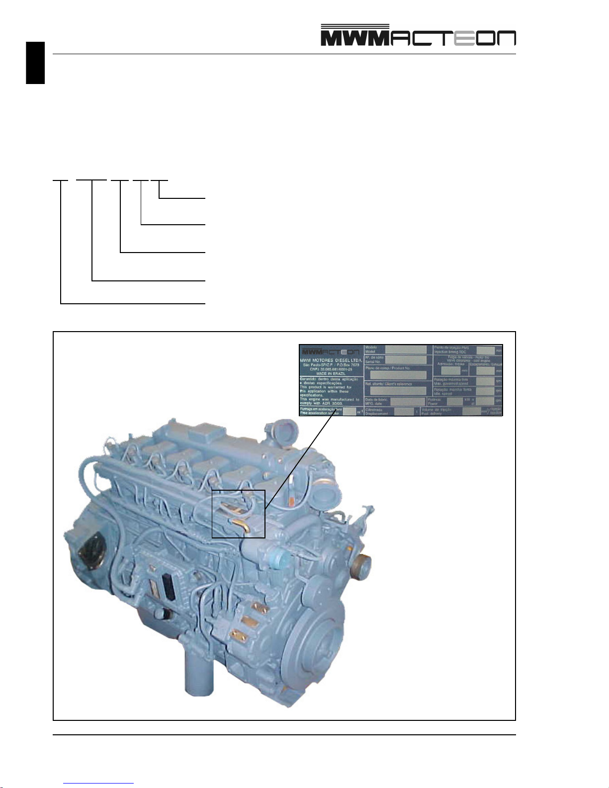
6.12 TCE
Turbocharged
Cylinders numbers
Series
Aftercooler
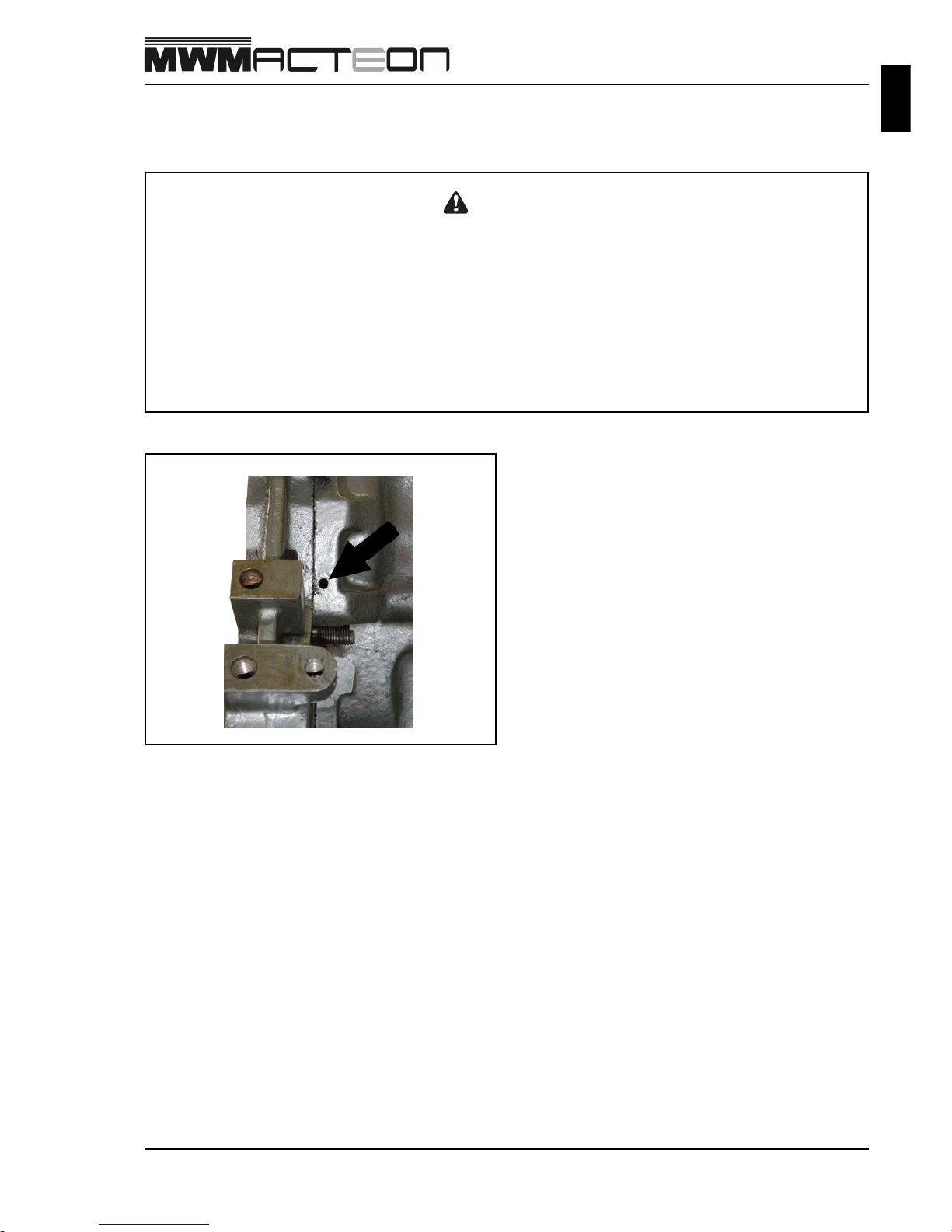
Identification and Location of the Serial Number
The engine identification and serial number can be found in the following places:
1 . Identification plate on the water pipe.
2 . Engraving on the right side of the engine block, close to the cylinder head of the cylinder #3.
Electronic
Presentation
1 - 7
9.612.0.006.7160 - 05/04
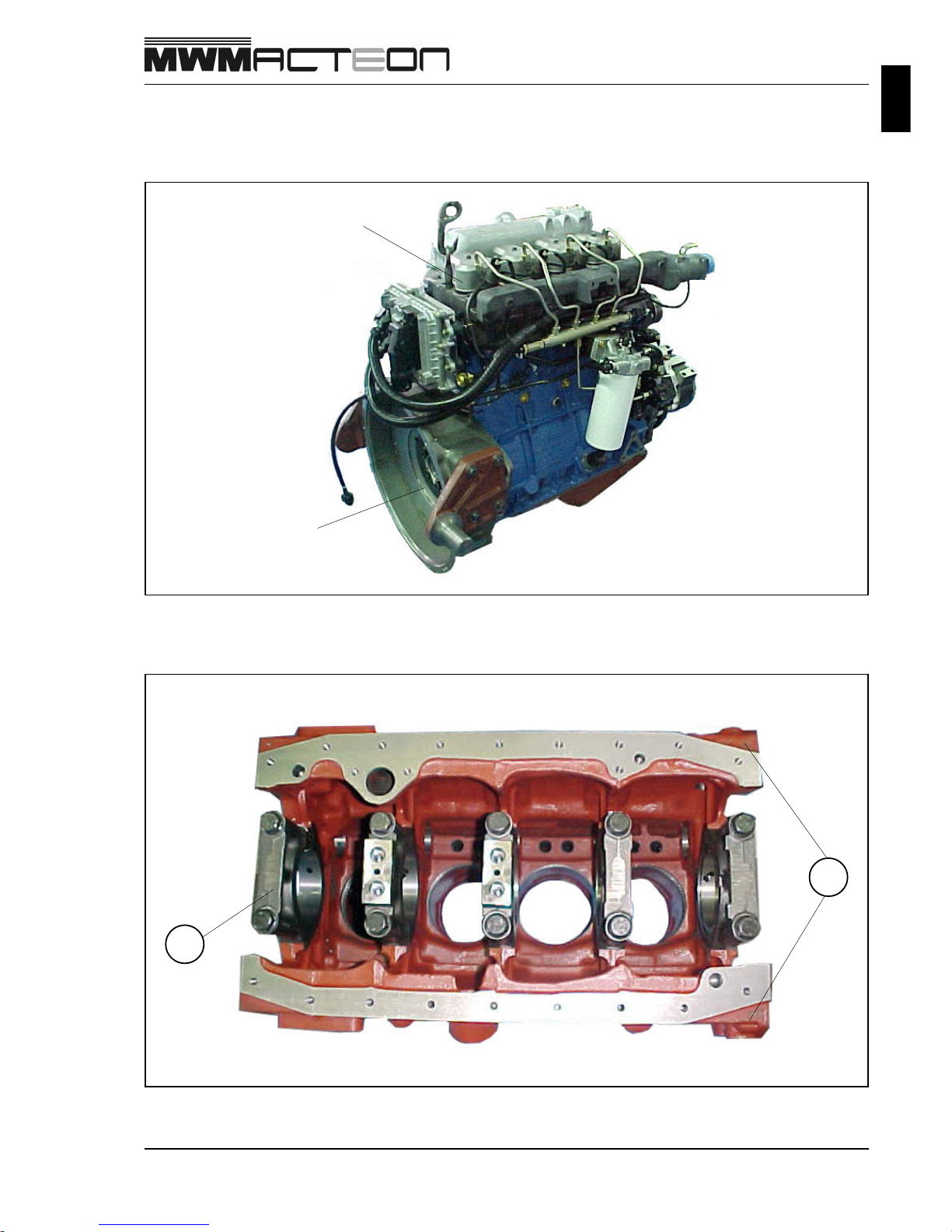
Cylinders Numeration
The numeration of the cylinders starts from the flywheel, according to the illustration below.
During the assembly , check the n umbers on the block (A) and on the bearings (B), which indicates the right assembly
position.
B
A
Cylinder #1
Flywheel

NOTES
1 - 8
9.612.0.006.7160 - 05/04

Tec hnical Data
2 - 1
9.612.0.006.7160 - 05/04
Technical Data
Tec hnical Data ................................................................................................................................... 2-2
Fuel System ........................................................................................................................ 2-2
Lubrication System ............................................................................................................ 2-3
Cooling System .................................................................................................................. 2-3
Thermostat .......................................................................................................................... 2-3
2 - 2
Tec hnical Data
9.612.0.006.7160 - 05/04
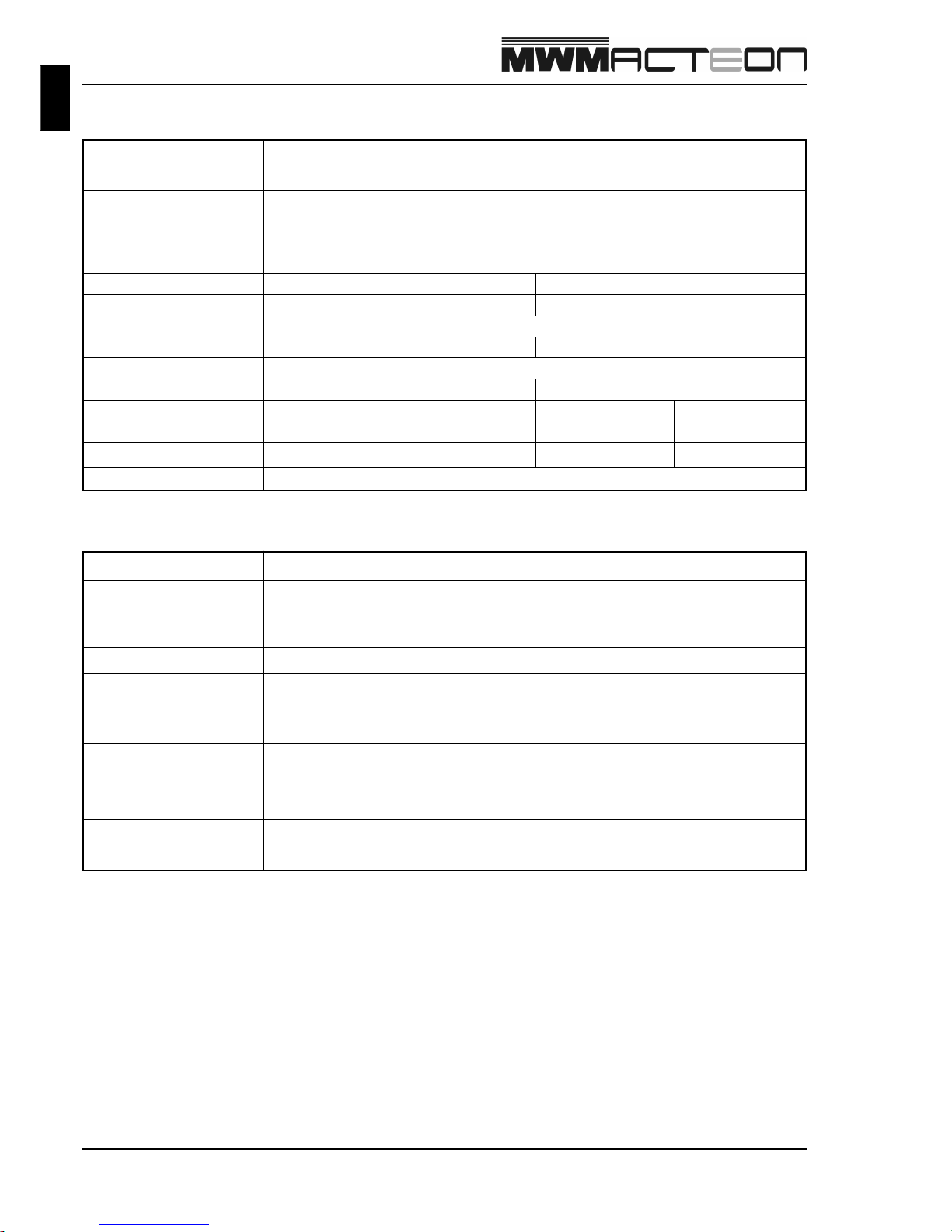
Fuel System
Description
Maximum fuel inlet
restriction (for gears
pump)
0.6 to 1.2 bar
Rail pressure
350 to 1400 bar
Fuel pressure strip in the
fuel filter outlet (at crank
speed)
Technical Data
Engine Data 4.12TCE 6.12TCE
Engine type
Vertical cylinders in line, 4 strokes
Injection type Direct with electronic management
Cylinder bore 105 mm
Cylinder stroke 137 mm
Unit displacement
1,2 l
4,745 litres 7,118 litres
T otal displacement
46
Quantity of cylinders
Compression rate
Firing order
1 - 3 - 4 - 2 1 - 5 - 3 - 6 - 2 - 4
Rotation sense Counter clockwise (seen by flywheel side)
~450 Kg ~570 KgDry engine weight
16,8:1
4 Cylinders 6 Cylinders
150 hp 260 hp
Po wer
500 NmT o rque
210 hp
105 kW 191 kW152 kW
900 Nm700 Nm
0,2 to 0,4 mmValves c learance (cold)
Strip of fuel pressure in
fuel filter fuel inlet (at
operation speed)
9.7 to 12.8 bar
Maximum pressure
reduction in fuel filter
≤
0,8 bar
10,5 to 13 bar
Tec hnical Data
2 - 3
9.612.0.006.7160 - 05/04
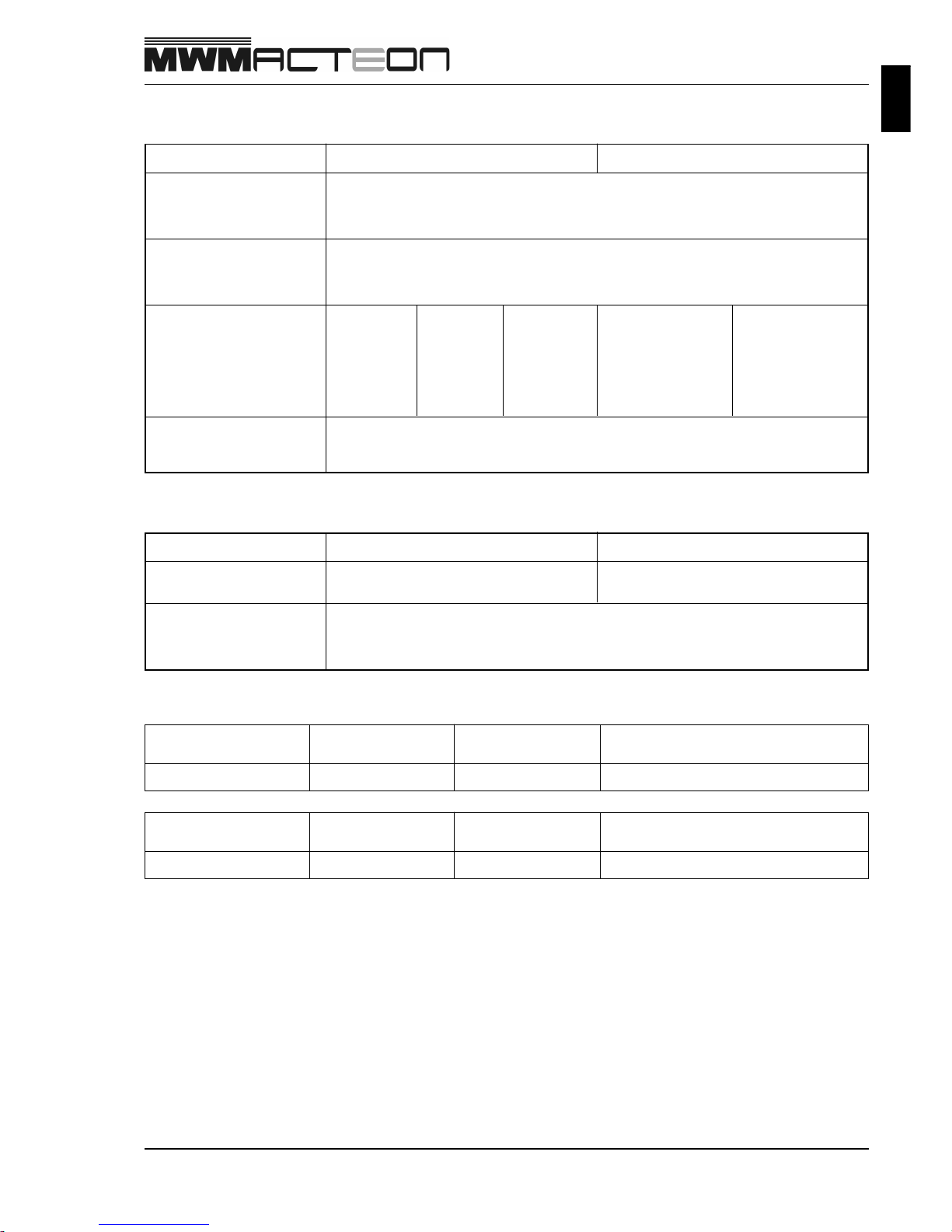
Thermostat
Lubrication System
Description
Oil pressure
• Nominal speed
• Idling speed
4.5 bar (hot engine)
1.0 bar (hot engine)
Oil temperature
• Nominal
• Maximum
90 - 110 °C
120 °C
Oil capacity
• Minimum
• Maximum (without filter)
• Maximum (with filter)
Description
V olume of water in the
engine, without radiator
Water temperature
• Nominal
• Maximum
Cooling System
4.12TCE 6.12TCE
5 l
8 l
9,2 l
4.12TCE 6.12TCE
80 - 90 °C
100 °C
13 l
17 l
18,7 l
7 l 9 l
• Variation pressure of the
filter to open by-pass
2,5
+ 1,2 bar
- 0,3 bar
Opening beginning Total opening
17.210E OD
Thermostat
9.412.0.757.001.6 75 ± 2°C 90°C
Minimum operation course
10.0 mm
Opening beginning Total opening
9.150E / 17.260E OT
Thermostat
9.412.0.757.002.6 80 ± 2°C 95°C
Minimum operation course
10.0 mm
13 l
17 l
18,2 l
17 l
29 l
30,2 l
23 l
32 l
33,7 l
2 - 4
9.612.0.006.7160 - 05/04
NOTES

Operation and Maintenance
3 - 1
9.612.0.006.7160 - 05/04
Operation and Maintenance
Engine Operation.............................................................................................................................. 3-2
Cooling fluid and Coolant ................................................................................................................ 3-5
Level Check ............................................................................................................................. 3-5
Cooling Fluid Filling Procedure ...................................................................................................... 3-6
Maintenance Table ............................................................................................................................ 3-7
MWM Acteon Engines - Vehicular.......................................................................................... 3-7
Conservation for Inactive Engines for Long Periods...................................................................... 3-8

3 - 2
Operation and Maintenance
9.612.0.006.7160 - 06/04
Operation and Maintenance
Engine operation
Start
Before operating the MWM Acteon engine check:
• Water le vel.
• Fuel level.
• Lubricant level.
• Soon after to start the engine, heat it up at medium speed, without load. Watch lubricant oil pressure and water
temperature.
• It is recommended to start the engine without accelerating, keeping the engine at idling speed for 30 seconds in
order to pre-lubricate the turbocharger.
• Before stopping the engine, run about 30 seconds at idling speed so that the turbo decrease its speed.
Cold Start
The difficulty of start at very low temperatures can happen due to the collapse of the filter because paraffin formation
or lack of ignition of the fuel.
The following actions can be observed:
• Use winter fuel, which does not form paraffinic flakes at low temperatures, or;
• Case the winter fuel is not available, it is necessary that the filter has a heater on the cylinder head to allow fuel
flow before the start.
Turbocharger Cares
Almost all failures in turbochargers are caused by lubrication deficiency (delay in lubrication,
restriction or lack of oil, intake of impurities in the oil, etc.) or objects or impurities entrance through
intake.
To maximize the turbo lifetime follow these cautions:
• Do not accelerate the engine immediately after the start.
• Wait 30 seconds with the engine at idling speed bef ore stop it.
• Pre-lubricate the turbocharger after oil change or other service that evolves oil drain. Crank the engine a few
times before start the engine. Then run the engine and allow it to run at idling speed for a period of time to
establish a complete circulation and oil pressure before to perform high speeds and load.
• In low temperatures or when the engine is being reactivated after a long period without operation, start the engine
and let it running at idling speed before operating in high speeds.
• Av oid operating the engine at idling speed for long periods of time.

Operation and Maintenance
3 - 3
9.612.0.006.7160 - 05/04
Running-in
OAll MWM engines are assembled and tested in the factory, making sure its immediate operation.
Howev er , it needs to be correctly ran-in, regarding that its performance and durability depend, largely, on the cares
taken during first operation phase.
As general rule, it is considered as running-in period the first 2,000 km for vehicular engines or the firsts 50 service
hours for stationary , industrial and agriculture engines. The vehicle or equipment moder ate operation has decisiv e
importance to its durability , service safety and econom y.
During this period it is very important to follo w these recommendations:
• Carefully check if engine oil level is correct;
• Carefully check if water level of the engine cooling system is correct;
• Av oid forcing the engine at high speeds , that is to say, to do not apply extreme conditions of load or , in the case
of the vehicular , to "stretch out" the speeds;
• Av oid forcing the engine at lo w speeds;
• Av oid forcing the engine while it has not reached the normal operation temperature yet;
• Av oid operating o ver the limit of 3/4 (75%) of the maxim um load of the vehicle or equipment;
• Av oid operating the engine at constant speeds for long periods of time;
• Av oid leaving the engine running at idling speed for a long period of time;
Strictly follow the maintenance instructions.
Following these recommendations the useful life of the engine will be prolonged.
Fuel Specifications
MWM Acteon engine must operate with regular Diesel fuel. It is recommended to use fuel of specification according
to the Brazilian Resolution CNP nr. 07/80 of P etroleum National Council.
The fog point (beginning of paraffin segregation) must be below the ambient temperature and the Cetan index must
not be less than 40.
Lubricant oil
Oil Level Check
• Stop the engine and wait 30 minutes so that the oil can flow bac k to the carter.
• Make sure that the vehicle is levelled.
• Before pulling oil dipstick, clean the surroundings.
• If necessary complete up to the upper mark (MAXIMUM), without exceeding it. Use the same oil mark and type
to complete the level.
• Do not operate the engine with the level below the lower mark (MINIMUM).
• Use only recommended lubricant oil.
• Do not mix different oil brands.
• Chosen an oil type and brand, always use the same.
3 - 4
Operation and Maintenance
9.612.0.006.7160 - 05/04
Check Lubricant oil Condition
The condition of the lubricant oil is very important for a good conservation of the inner components of the engine .
Attention
• Always use genuine MWM filter.
Oil Change
• The oil must be hot to facilitate the drainage.
• Drain the oil removing the carter plug.
• Wait until not leaving oil an ymore.
• Install the plug with a new washer and tighten according to the specification.
• Fill with recommended lubricant oil up to upper level mark (MAXIMUM) of the dipstick.
Oil Filter Change
• Clean the sealing area of the filter with a clean and without threads cloth.
• Lubricate the filter gasket and manually screw until touch.
• Manually tighten.
• Fill up with new oil. In a levelled vehicle, the oil level must reach the upper mark of the dipstick.
• Run the engine checking the sealing of the filter and carter plug.
• Stop the engine and, after 30 minutes, check oil le v el again, filling up if necessary.
Lubricant Oil
The lubricant oil is very important for a good conservation of the inner components of the engine. Lubricant oil
contaminated with sand, soil, dust, water or fuel cause problems to the engine.
Check the appearance of the engine lubricant oil. A dark coloration and low viscosity could mean presence of fuel in
the lubricant oil. The presence of bu bbles or a milky color ation could indicate presence of water in the oil.
Lubricant Oil Specifications
It must be used multi-viscous type lubricant oil that accomplish, at least, to the API CG4 (or upper) specifications
and to the recommended viscosities.
Attention
• Do not mix different oil brands. Chosen one oil type, always use the same in the filling.
Operation and Maintenance
3 - 5
9.612.0.006.7160 - 06/04
Cooling Fluid and Coolant
Oil Level Check
Attention
• Do not open the expansion reservoir cap while the engine is hot.
• Check the level when the engine is cold.
• Check the level of the cooling system daily. If the level is not correct, add clean water +
MWM coolant according to the proportion recommended on the bottle.
• Carefully open the first stage of the cap relieving the vapour pressure.
• Check for leaks through cooling piping.
• Check the nominal pressure of the cap in case of change.
Water Pump Check
Check for leaks through the pump drain hole.
3 - 6
Operation and Maintenance
9.612.0.006.7160 - 05/04
Cooling System Cleaning
1. Remove the cap from the engine radiator or from the expansion reservoir of the vehicle;
2 . Drain the cooling system fluid through the lateral plug of the engine block;
3 . Flush the whole system until to leave only clean water;
4 . Close the system and fill with clean water;
5. Operate the engine until to reach the normal operation temperature and leave it running for 15 minutes;
Remark: If the vehicle has hot air conditioning, turn the button in hot position.
6. Stop the engine and wait to cool down;
7 . Open the drain, remove the radiator cap and leave the water to flow out all again;
8. Close the drain outlet and fill the system with clean water and MWM coolant according to the recommended proportion;
9 . Operate the engine up to the normal operation temperature and leave it running for 15 minutes;
Remark: If the vehicle has hot air conditioning, turn the button in hot position.
10. Check the level of the cooling system completing if it is necessary.
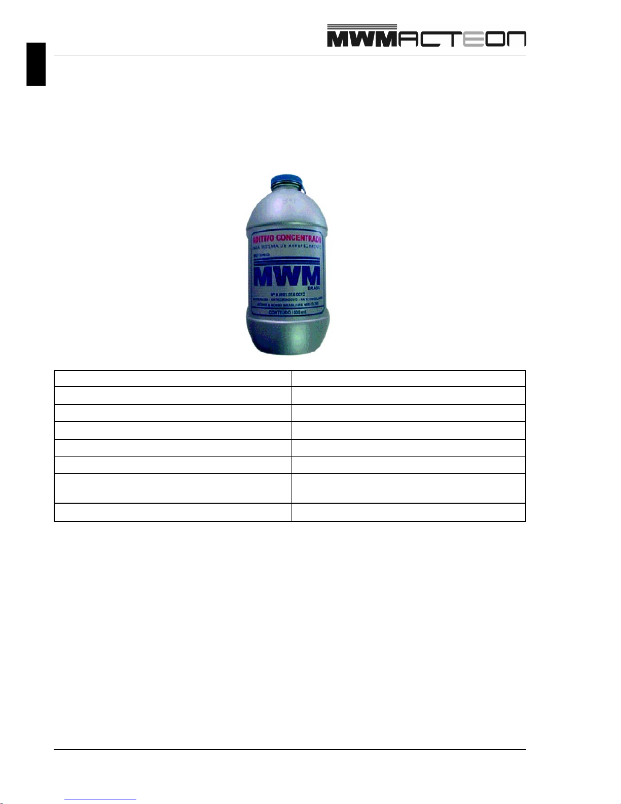
Cooling Fluid Filling Procedure
Fill the system with the necessary amount of MWM coolant and complete with clean water. Put the engine in
operation up to the normal operation temperature. Only complete the level of the system with clean water + MWM
coolant in the correct proportion.
After filled the system, operate the engine checking for leaks.
Denomination Concentrate Coolant
Properties Anticorrosive / Anti-boiling / Antifreeze
Application Modern Diesel Engines in General
Colour Red
Proportion 50% ± 10%
Change Interval 50,000 km or 6 months
Composition
Anticorrosive, Ethilenoglycol, Borates,
Silicates and Colouring
V alidity of the bottle 5 years
MWM COOLANT
Operation and Maintenance
3 - 7
9.612.0.006.7160 - 05/04
DRAIN FUEL FIL TER
30.000 Km
60.000 Km
120.000 Km
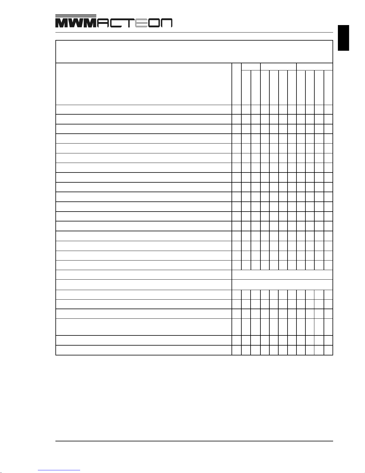
MAINTENANCE PLAN
A ) Up to 50,000 km/year conditions
B ) Over than 50,000 km/year conditions
•
•
•
•
•
•
MAINTENANCE TABLE
MWM ACTEON VEHICULAR ENGINES
Remark:
1)
This table is only for guidance . The Maintenance Table of the vehicle prevails ov er this tab le .
2)
For heavy-duty and off-road services perform maintenance in the half of the indicated periods in the
table above.
3)
If the engine stays inactive f or a long time, it must perf orm an idling speed test fortnightly , until to reach
the operation temperature.
4)
Independent of the intervals indicated for engine lubricant oil changes, it must be changed at each
6 months.
5)
Electronic parts of BOSCH (phase, speed, air pressure and temperature, oil pressure and temperature,
water temperature sensors) are free of maintenance and checked by recommended diagnose scanner
with errors stored in failure memory .
•
•
15.000 Km
80.000 Km
40.000 Km
20.000 Km
10.000 Km
5.000 Km
2.500 Km
Daily
CHECK LUBRICANT OIL LEVEL
COLLECT SAMPLE OF LUBRICANT OIL T O ANALYSIS
CHECK COOLANT LEVEL
CHECK FOR LEAKS IN THE ENGINE
CHECK CONNECTIONS
CHANGE LUBRICANT OIL (SAE 15W40 - API CH-4)
CHANGE LUBRICANT OIL FIL TER
CHANGE FUEL FIL TER
CHANGE AIR FIL TER
CLEAN AIR FIL TER (if necessary)
ADJUST V AL VES CLEARANCE
CHECK DAMPER CONDITIONS
CHECK BEL T
CHANGE BEL T
CHANGE COOLANT
CHECK FUEL PIPING CONDITIONS
NOZZLES
HIGH-PRESSURE FUEL PUMP
CHECK ELECTRIC CONNECTIONS (Starter Motor and Alternator)
CLEAN AND RETIGHTEN BA TTER Y TERMINALS
RETIGHTEN ENGINE FIXA TION CUSHIONS
CHECK THE TIGHTENING OF THE SCREWS AND NUTS: EXHA UST
MANIFOLD AND ELBOW , TURBOCHARGER FLANGE AND CARTER
CHECK F AN
CHECK TURBOCHARGER (shaft clear ance and carcass condition)
••
••
•••
•••
••
•
•
•
FREE OF MAINTENANCE
FREE OF MAINTENANCE
•
•
•
••
•
•
•
••
•
•
•
•
•
•
•
••
•
•
•• •
BAInitial

3 - 8
Operation and Maintenance
9.612.0.006.7160 - 05/04
Conservation for Inactive Engines for Long Period
MWM engines are produced protected for , at the most, 3 inactivity months under shut shelter .
When the engine is to stay inactive for a long period, it is necessary to follow these cares:
1 . Clean the outer parts of the engine.
2 . Operate the engine until to reach the operation normal temperature.
3 . Drain cooling system and lubricant oil.
4 . Fill the radiator with clean water + MWM coolant according to the recommended proportion.
5 . Fill up the carter with protective oil SAE 20 W 20.
6 . Drain fuel system (reservoir, lo w pressure system).
7 . Operate the engine for 15 minutes at 2/3 of the nominal speed, without load, using a mixture of fuel with 15% of
the protective oil SAE 20 W 20.
8. Drain fluid from cooling system and oil from carter. The fuel mixture can sta y in the system.
9. Remove valves cover from cylinder heads and spray protective oil on the springs and rocker arms. Reinstall
covers.
10. Remove fuel injectors and spray 10 to 15 cm³ of protective oil in each cylinder with the respective piston at
bottom-dead-centre position. Turn crankshaft a complete turn and reinstall fuel injectors.
11. Apply protective grease on articulations.
12. Apply protective oil on machined surfaces.
13 . Remove belt(s).
14 . Seal all the holes of the engine, to avoid dust and water penetration.
Remarks:
• Renew the engine conservation procedure after each 8 months of inactivity .
• In case of new brand engines, do not consider items 1, 2 and 3.
Preparation of the Engine to Return to Service
Before operating an engine which stayed inactive for a long period, follow these procedures:
1 . Clean the outer parts of the engine.
2 . Fill cooling system with clean water and MWM coolant in the recommended proportion.
3 . Change engine lubricant oil filter.
4 . Fill the carter with new lubricant oil according recommendation.
5 . Install belt(s) and adjust tension.
6 . Remove valves cover and lubricate rocker arms with engine oil. Reinstall covers.
7 . Drain the fuel mixture from the reservoir and fill with new fuel.
8 . Change fuel filter.
Operation and Maintenance
3 - 9
9.612.0.006.7160 - 05/04
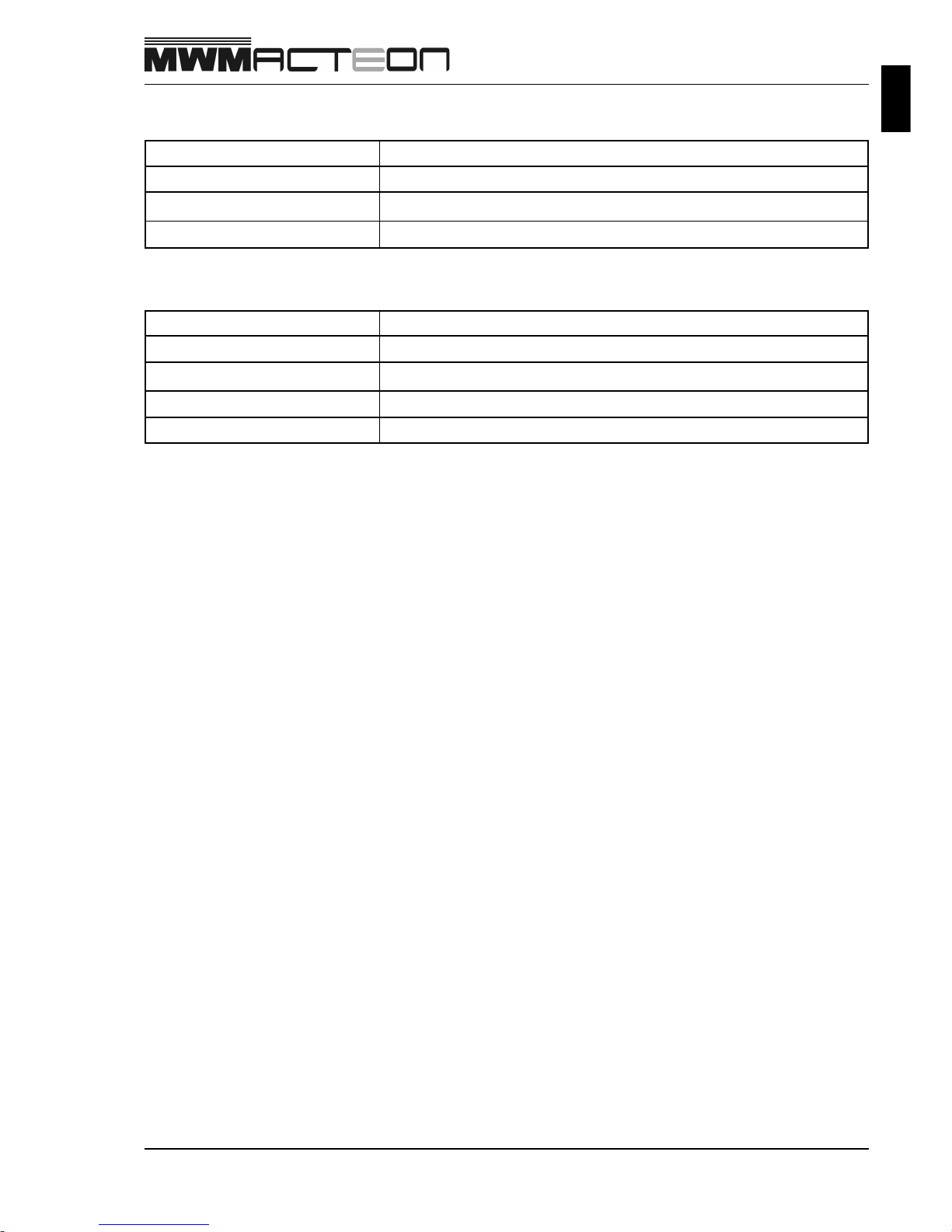
Protective Oils
Manufacturer Recommended Products (*)
Castrol Rustilo 652 (SAE 20)
Texaco Engine Oil DBH 20 W 20
Ipiranga Ultramo T urbo SAE 20
Graxas
(* ) Other products with similar technical features could be used with a previous approval of MWM.
Manufacturer Recommended Products (*)
Castrol LM 2
Texaco Marlfac MP2
Ipiranga Ipiflex 2
Petrobrás Lubrax GMA-2

NOTES
3 - 10
9.612.0.006.7160 - 05/04

Engine Block
4 - 1
9.612.0.006.7160 - 05/04
Engine Block
Disassembly Notes ........................................................................................................................... 4-2
Pre-Assembly Inspections and Measurements ............................................................................... 4-3
Liner Protrusion Specification..................................................................................... 4-3
Liners Specification...................................................................................................... 4-4
Liners and Pistons Assembly Specifications ............................................................. 4-5
Engine Block Specifications ........................................................................................ 4-6
Inspections and Measurements ....................................................................................................... 4-8
Assembly......................................................................................................................................... 4-10
4 - 2
Engine Block
9.612.0.006.7160 - 05/04
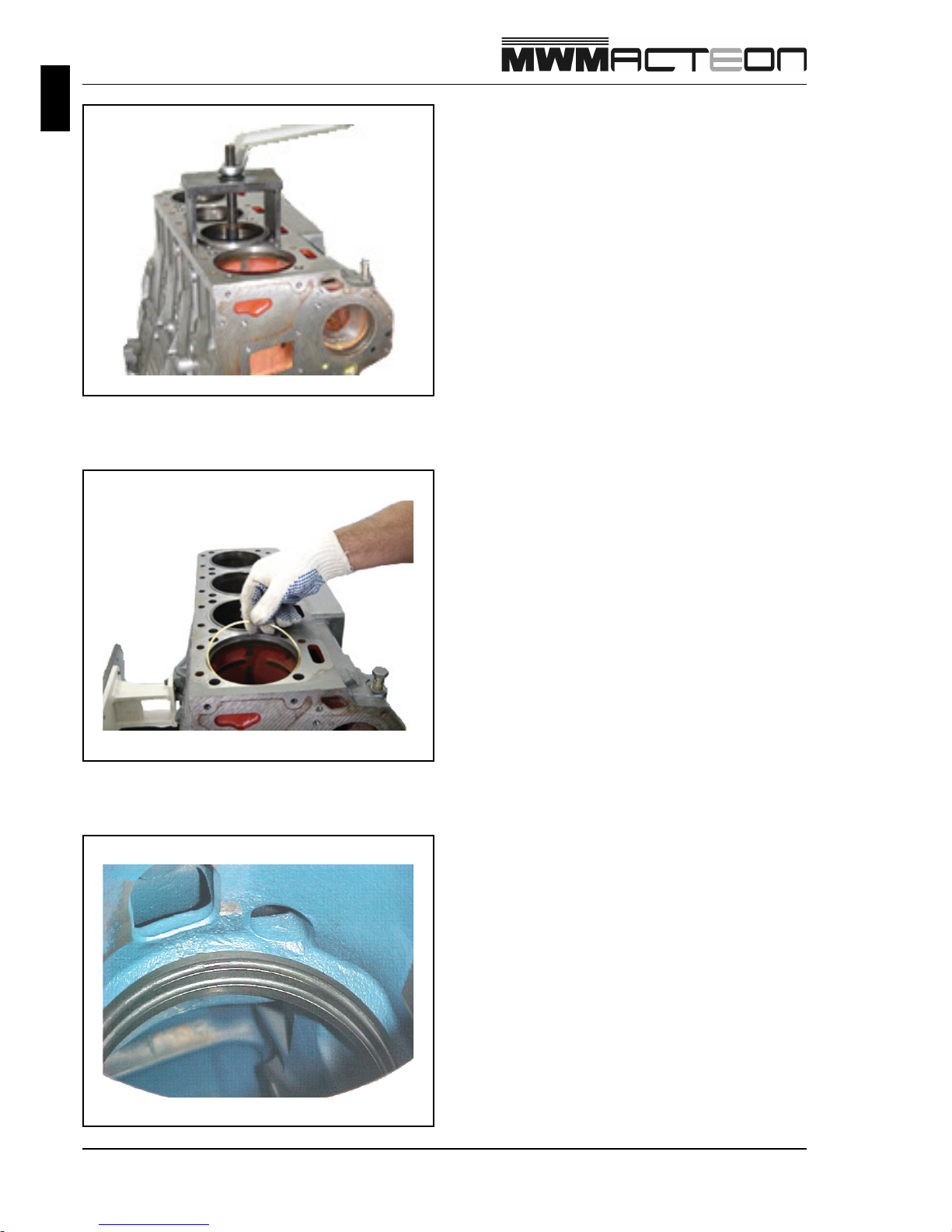
Remove T ombak rings.
Disassembly Notes
The cylinder liners removal must be made with the
special tool MWM nr. 9.610.0.690.017.6 in order to do
not damage the engine block or the liners.
The lower part of the tool must be fitted on the lower
edge of the liner.
The liner can be removed screwing the nut of the puller .
Remove liners sealing rings.
Engine Block
4 - 3
9.612.0.006.7160 - 05/04
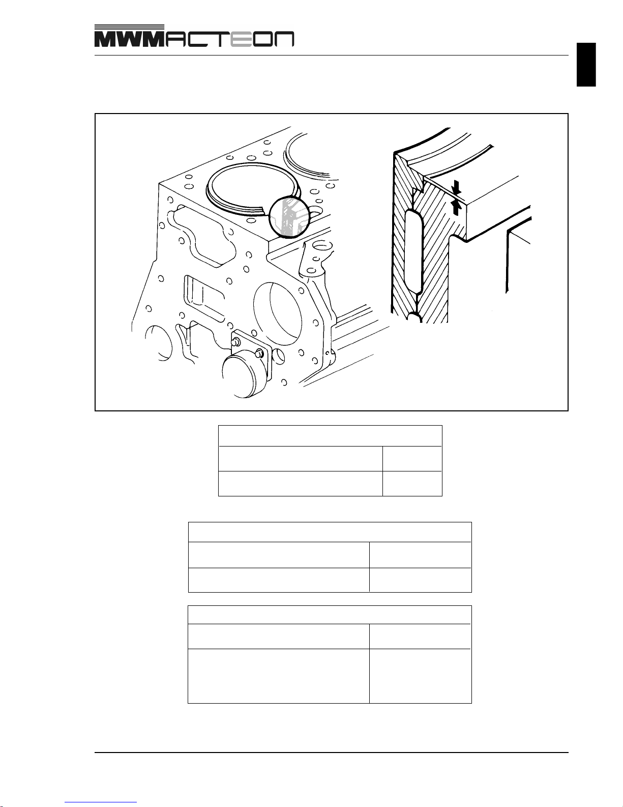
Pre-Assembly Inspections and Measurements
Liner Protrusion Specification
Protrusion Adjustment Shims (when necessary)
Thickness mm
9.612.8.340.004.4 0.05
9.612.8.340.005.4 0.10
9.612.8.340.006.4 0.20
9.612.8.340.007.4 0.50
Liner over Engine Block Surface
Measure mm
Protrusion *0.04 - 0.09
TOMBAK Ring
Thickness mm
9.612.0.340.002.4 0.15
*Affect emissions level

4 - 4
Engine Block
9.612.0.006.7160 - 05/04
Pre-Assembly Inspections and Measurements
Liners Specification
Liners
Measure mm
Maximum waste 0.06
Out-of-roundness 0.02
Ø Inner 105.000 - 105.022
Engine Block
4 - 5
9.612.0.006.7160 - 05/04
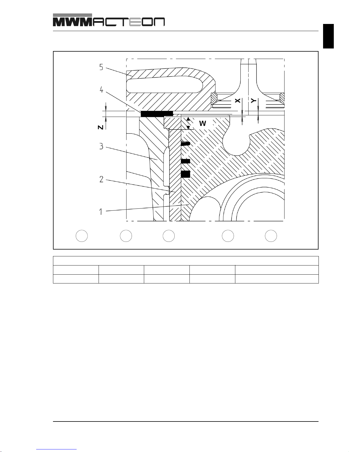
Liners and Pistons Assembly Specifications
1
Piston
2
Liner
3
Engine Block
4
Gasket
Liners Assembly
W X Y Z Gasket nr. / Application
0.23 to 0.59
8.04 to 8.06 0.95 to 1.10 1.35 to 1.69 9.612.0.854.003.4 / Spare part
5
Cylinder head
4 - 6
Engine Block
9.612.0.006.7160 - 05/04
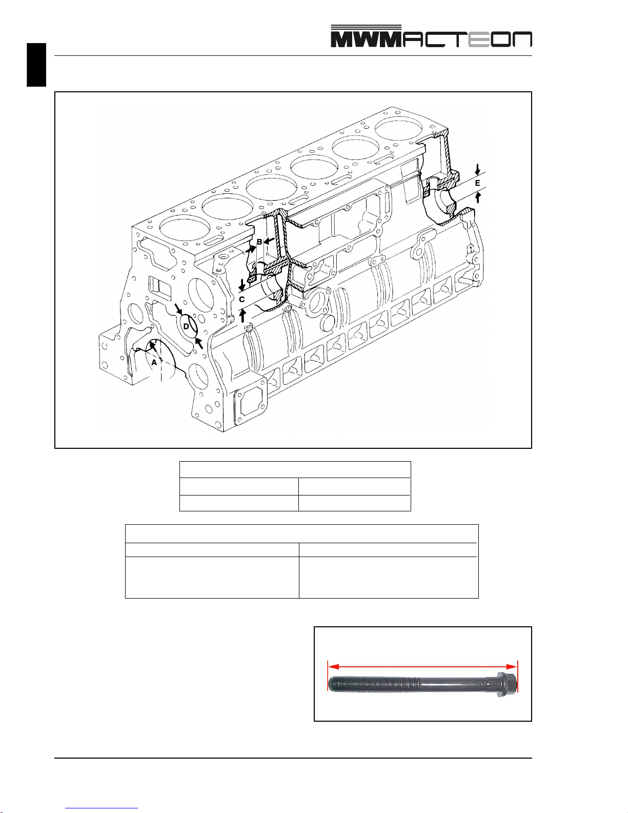
Engine Block Specifications
Main Bearings (A)
Diameter mm
Inner 92.000 - 92.022
Tappets Housing (B)
Ø Inner mm
standard, nominal 18.000 - 18.018
standard, maximum 18.020
1st repair 18.500 - 18.518
Measure main bearings bolt lengths.
Discard bolts longer than 133.5 mm.
L
 Loading...