

MW Fly B22 AeroPower, B25 AeroPower Operation Manual
Manual B – Operations - 1
Manual B
OPERATIONS MANUAL
B22
B25
Applicable to: B22 and B25 (all versions) Revision 1.3 – 02/24/2015
AeroPower
AeroPower

Manual B – Operations - 2
Before attempting any engine start carefully read Manual A containing
important safety information. Not following safety procedures could cause
severe injury or loss of life. Consult the aircraft instruction manual for more
information on safety.
All information, illustrations, instructions and technical data contained in this manual has been upgraded
before printing. MW Fly reserves the right to modify, correct or upgrade general data at any time without any
obligation or prior consent from third parties. Publication of any part of this document without written consent
of MW Fly is strictly prohibited.
This Manual forms part of the engine and must be kept safe. It must accompany the engine in case of sale to a
new owner. The original document is written in Italian and this language will be used to settle any dispute of a
legal or technical nature.
Applicable to: B22 and B25 (all versions) Revision 1.3 – 02/24/2015

Manual B – Operations - 3
B.1. SUMMARY 7
B.2. INTRODUCTION 7
B.2.1. Statement 7
B.2.2. Consultation Notes 7
B.2.3. Identification Data 9
B.2.4. MW Fly Authorized Service Centers 9
B.3. SAFETY 10
B.3.1. Statement 10
B.3.2. Safety Elements 10
B.3.2.1. Passive Safety 10
B.3.2.2. Active Safety Elements 12
B.3.3. Warning labels 14
B.3.3.1. Engine Oil Filler Cup 14
B.3.3.2. Reduction Gear Box Oil Filler Cup 14
B.3.3.3 Water Expansion Tank 15
B.3.3.4. Air Filter 15
B.3.3.5. ECU 15
B.3.3.6. Head Cover 15
B.3.3.7. Reduction Gear Box 15
B.3.3.8. Governor 16
B.3.3.9. Water Circuit Arrows 16
B.3.3.10. Fuel Circuit Arrows 16
B.3.4. Modifications and Accessories 17
B.3.4.1. Original Accessories 17
B.3.5. Use of the Technical Documentation 18
B.4. ENGINE DESCRIPTION 19
B.4.1. General Characteristics 19
B.4.2. Engine Models 19
B.4.3. Cylinder Numeration and Position 20
B.5. TECHNICAL CHARATERISTICS 21
B.5.1. End Use 21
B.5.2. Dimension 22
B.5.3. Weight 24
B.5.3.1. Optional Accessory Weight 24
B.5.4. Performance 24
B.5.4.1. B22D 27
B.5.4.2. B22H 29
B.5.4.3. B22L 30
B.5.4.4. B22R 32
B.5.4.5 B25D 34
B.5.4.17.C 34
Applicable to: B22 and B25 (all versions) Revision 1.3 – 02/24/2015

Manual B – Operations - 4
5
10
15
20
25
30
35
40
2000 2250 2500 2750 3000 3250 3500 3750 4000 4250
[L/h]
[RPM]
B25L Consumption @ constant MAP
29.9
28.5
27
25.5
24
22.5
B.5.4.6. B25H 36
B.5.4.7. B25L 37
B.5.4.8. B25R 39
B.5.4.9. Performance Variation 41
B.5.5. Ratio Power/Weight 42
B.5.6. Fuel Consumption 42
B.5.6.1. B22D 44
B.5.6.2. B22H 46
B.5.6.3. B22L 47
B.5.6.4. B22R 49
B.5.6.5. B25D 51
B.5.6.6. B25H 53
B.5.6.7. B25L
54
B.5.6.8. B25R 56
B.5.7. Propeller speed 58
B.5.8. Direction of the Rotation of the Propeller 58
B.6. DESCRIPTION OF THE SYSTEMS 60
B.6.1. Cooling system 60
B.6.2. Lubricant system 61
B.6.3. Fuel system 62
B.6.4. Electric system 63
B.6.4.1. ES-m Instrumentation 64
Applicable to: B22 and B25 (all versions) Revision 1.3 – 02/24/2015

Manual B – Operations - 5
B.7. OPERATING INSTRUCTION 65
B.7.1. Operating limits 65
B.7.1.1. RPM 65
B.7.1.2. Fuel Pressure 66
B.7.1.3. Engine oil pressure 66
B.7.1.4. Engine Oil Temperature 67
B.7.1.5. Reduction Gear Box Oil Temperature 67
B.7.1.6. Coolant Temperature 68
B.7.1.7. Air Intake Temperature 68
B.7.1.8. Load Factor 69
B.7.1.9. Inclination Angle 69
B.7.1.10 Electrical Voltage 70
B.7.2. Operative Fluid 70
B.7.2.1. Cooling Fluid 70
B.7.2.2. Engine Oil 70
B.7.2.3. Reduction Gear Box Oil 71
B.7.2.4. Fuel 71
B.7.3. General Criteria to Operate the Engine 72
B.7.3.1. Check Before Start 72
B.7.3.2. Start Operation 75
B.7.3.3. Engine Warm Up 76
B.7.3.4. Before Take Off 77
B.7.3.5. Take Off 78
B.7.3.6. Cruise 78
B.7.3.7. Landing 78
B.7.3.8. Engine Switch off 79
B.7.3.9. Use of the Engine in Winter Season 79
B.7.4. Behavior in Case of Emergency 81
B.7.4.1. Accidental Engine Stop – Start During Flight 81
B.7.4.2. Over Rev 81
B.7.4.3. Exceeding the Maximum Coolant Temperature 81
B.7.4.4. Exceeding the Maximum Oil Temperature 82
B.7.4.5. Oil Pressure Below the Limit in Flight 82
B.7.4.6. Oil Pressure Below the Limit on the Ground 82
B.7.4.7. Fuel Pressure Below the Limit in Flight 82
B.7.4.8. Fuel Pressure Below the Limit on the Ground 83
B.7.4.9. Battery Voltage Over the Limit 83
B.7.4.10. Battery Voltage Below the Limit 83
B.7.4.11. ECU Alarm 84
B.7.4.12. Generator Alarm 84
B.7.4.13. Abnormal Vibration 84
B.7.4.14. Irregular Operation 85
Applicable to: B22 and B25 (all versions) Revision 1.3 – 02/24/2015

Manual B – Operations - 6
B.8. ENGINE CONTROL 86
B.8.1. List of Tool Kit for the Pre-flight Checks or Emergency 86
B.8.2. Shelter from Service for Extended Period of Time 86
B.8.3. Return to Service After Long Inactivity 86
B.8.4. Engine Protection When Used in Cold Climates 87
B.9. MALFUNCTION RESOLUTION 88
B.9.1. Operation Malfunctions and Their Resolution 88
B.9.2. Anomalies to the Injection and Ignition Systems 89
B.9.3. Signal Engine Malfunction 90
B.10. AUTHORIZED DISTRIBUTOR 92
B.11. MANUAL UPDATE LIST 93
Applicable to: B22 and B25 (all versions) Revision 1.3 – 02/24/2015

Manual B – Operations - 7
This engine has not received any certification for aeronautical use.
It must be used exclusively on experimental aircraft where an engine failure
will not compromise flight safety. Its use in cetified aircraft is strictly
prohibited.
Operate the engine in compliance with the local rules and laws.
B.1. SUMMARY
B.2. INTRODUCTION
The A eroPower series of engines are designed and manufactured using the most modern
motor technology with the purpose of achieving good performance combined with a high level of
passive safety. If the engine is used correctly it will return years of pleasure and reliable service.
Please read this manual carefully before using the engine and apply all safety standards contained
in it, in addition to those that your experience and common sense suggest.
Remember that regular maintenance and careful inspection of the engine before flight are essential
safety factors.
MW Fly will be happy to provide additional information and all the technical support you will
need.
B.2.1. Statement
The purpose of this operations manual is to provide the users of the AeroPower engine
family with the basic operating instructions and safety information. Prior to commencing to
operate the engine it is crucial to read and understand the contents of this document. If any part of
this manual is unclear or there are any doubts on the interpretation, contact an MW Fly service
center.
For additional or more detailed information consult the Maintenance Manual and the Additional
Maintenance Manual.
It is fundamental to integrate the information of this manual with the safety precautions of the
aircraft manufacturer and with safety conditions from your personal experience.
B.2.2. Consultation Notes
This manual was originally printed in Italian. This will be the only language used for any
reference or dispute.
This manual is divided into sections, chapters and paragraphs. The paragraphs could be partitioned
into one or more topics. The title of each section, chapter and paragraph is indicated as follows:
SECTION
Chapter
Paragraph
Topic
Applicable to: B22 and B25 (all versions) Revision 1.3 – 02/24/2015
Manual B – Operations - 8
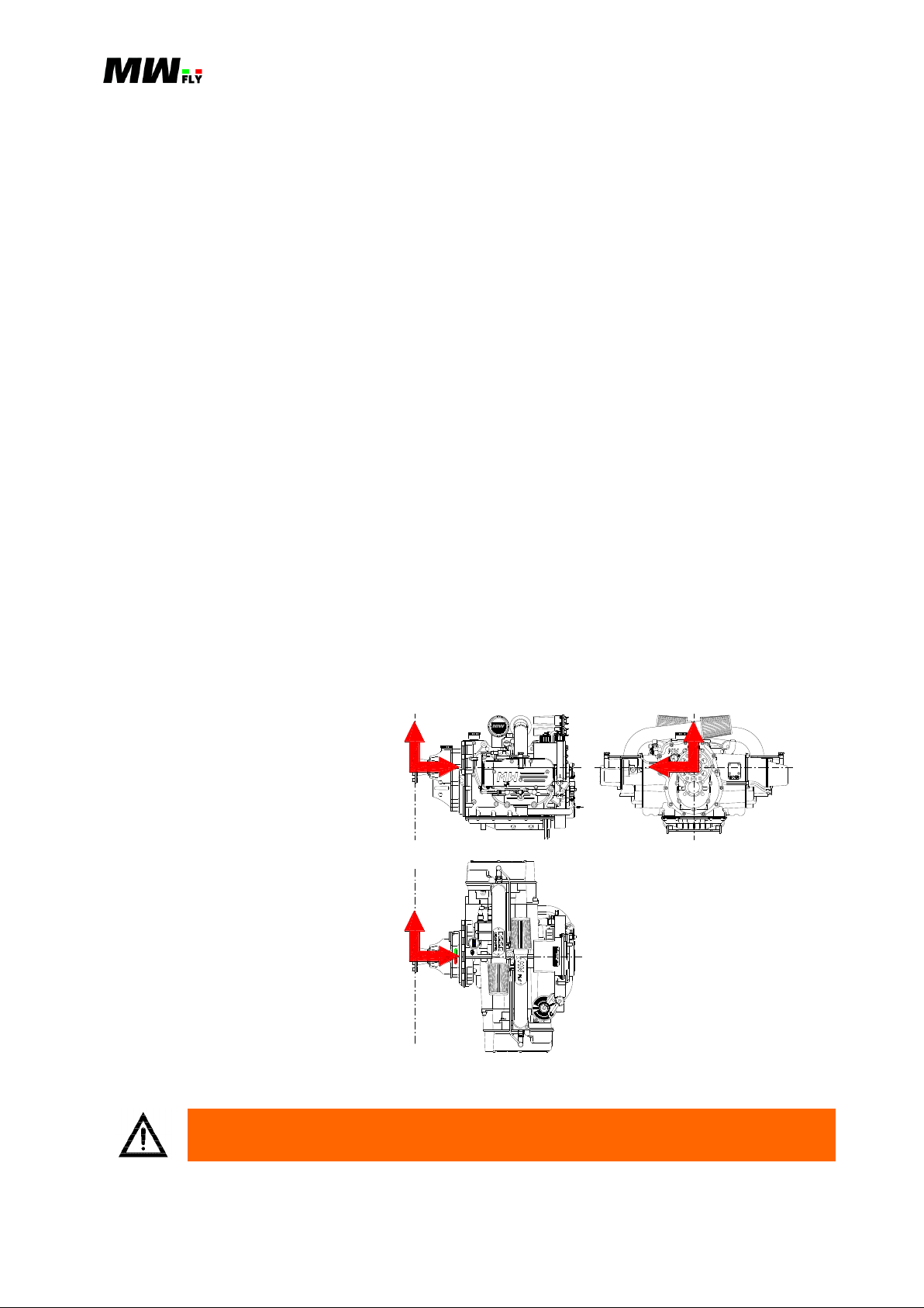
A 3D Cartesian coordinate
right hand is used in the
present manual. The axis
origin is on the propeller shaft.
In the intersection with the
propeller level on the propeller
flange, the x-axis positive
direction is towards the engine
(see picture B.2.2.1.P), the yaxis positive direction is
towards side #1, the z-axis
points up.
RAM
INTAKE
EFFECT
E
C
L
P
E
K
E
Y
D
N
A
D
R
FLY
A
N
T
S
G
S
Y
N
E
B
T
H
O
H
G
H
E
N
E
R
L
F
P
E
N
W
O
F
I
O
T
G
L
T
H
L
L
I
RESERVOIR
R
C
D
N
N
E
V
E
A
U
S
E
F
E
L
E
0
.
Y
7
A
P
A
C
I
O
C
I
L
O
L
E
T
E
H
C
E
C
K
L
V
M
O
L
A
N
T
O
T
/
2
N
E
P
U
K
N
O
3
Y
L
E
N
G
V
E
R
Y
2
C
E
H
A
E
C
Y
E
A
R
S
A
T
PRESSURIZED
Y
L
O
O
N
Y
C
L
PROTECT BEFORE WASHING
ONTROLUTHORITY
MAX OPERATING TEMPERATURE 85°C
CHECK WIRING LOOM BEFORE FLIGH T -
OPERATING ELECTRIC VOLTAGE 9-18V
NGINEIGITAL
FLY
ULL
BY
API GL-5 OR HIGHER
C
H
E
C
B
I
F
O
R
E
F
L
G
H
T
K
E
SAE 85W/140
T
I
C
A
P
A
C
3
.
0
Y
L
CTIVE AMPING ONTROL
GEAR
OIL
API SG OR HIGHER
C
H
E
C
B
I
F
O
R
E
F
L
G
H
T
K
E
SAE 15W/50
T
I
C
A
P
A
C
8
.
2
Y
L
ENGI NE
OIL
Z
X
Y
X
Y
Z
WARNING: Not following this instruction can cause severe personal injury or
loss of life.
B.2.2.1.P
The numeration is an alpha-numeric code that follows format below:
B.7.1.8.
The first letter indicates the type of manual:
A = installation manual
B = operations manual
C = maintenance manual
D = heavy maintenance manual
The first number (between the first and second dot): this number (one or two digits) indicates
the section.
The second number (between the second and third dot): this number (one or two digits)
indicates the chapter.
The third number (between the third and fourth dot): this number (one or two digit) indicates
the paragraph and is not always present.
The numeration of the pictures follows the same criteria for the first three parts of the code. The
third number is the number of the picture in the chapter. A letter P is added at the end of the code.
(e.g. B.5.8.2.P).
The numeration of the tables follows the same criteria for the first three parts of the code. The
third number is the number of the picture in the chapter. A letter C is added at the end of the code.
(e.g. B.5.8.2.C).
Specifications are given in the ST metric system (C.2.4.); in the table the measurement units are
indicated between square brackets [].
Symbols used in this manual have the following meaning:
Applicable to: B22 and B25 (all versions) Revision 1.3 – 02/24/2015
Manual B – Operations - 9
CAUTION: Not following this instruction could cause severe damage to the engine
or other components and possible engine failure.
NOTE: Refers to supplementary information to better understand or execute an
instruction.
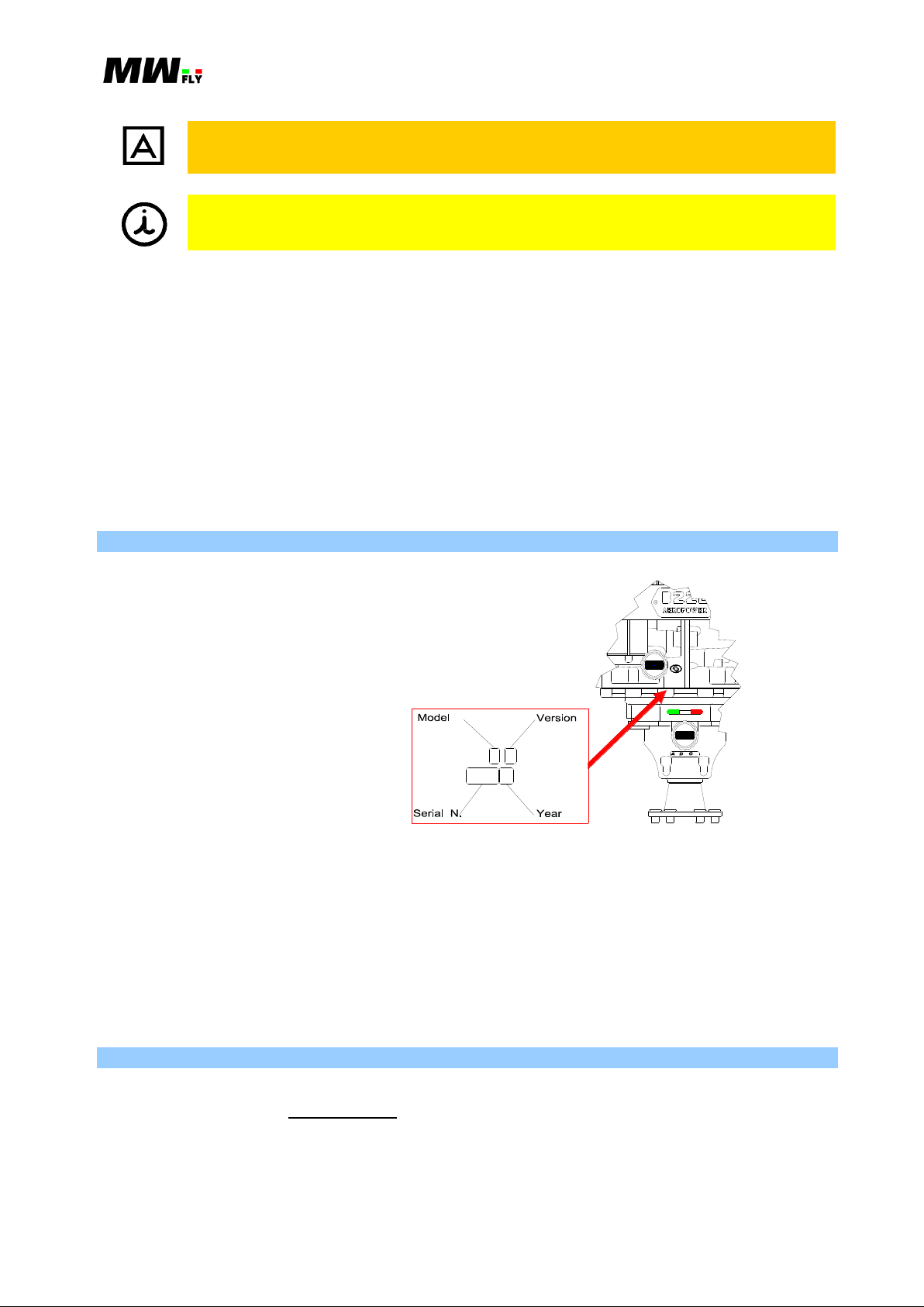
The Engine serial number is
located on the upper side of
crank case near oil dip stick.
It is composed of ten alpha
numeric codes where the third
and fourth symbol indicate
Model and Version, the
following four are the serial
number and the last two are
the year of manufacturing.
Identification code and
version is illustrated in chart
B.4.2.1.C.
API GL-5 OR HIGHER
C
H
E
C
B
I
F
O
R
E
F
L
G
H
T
K
E
SAE 85W/14 0
T
I
C
A
P
A
C
Y
3
.
0
GE A R
L
CTIVE AMPI NG ONTROL
OI L
API SG OR HI GHER
C
H
E
C
B
I
F
O
R
E
F
L
G
H
T
K
E
SAE 15W/50
T
I
C
A
P
A
C
8
.
2
Y
L
EN G IN E
OI L
B.2.3.1.P
1., 2., … This numbering is used to list tools and consumables needed to run an installation or
maintenance; it is also used to bring in parts lists or engine parts shown in the
illustrations.
a., b., … This numbering is used to indicate a list of actions or subjects with relation to inclusion:
all of the actions or options listed must be verified.
o This symbol is used to indicate a list of actions or subjects with relation to exclusion: only one
of the actions or options listed with this symbol must be verified.
This symbol is used to list the general characteristics of the engine, component specifications
or options for installation or maintenance.
B.2.3. Identification Data
The relationship between the engine serial number and the engine model is indicated in the table
B.4.2.1.C.
Deleting or modifying the serial number will revoke any warranty and obligation by MW Fly
toward current owner.
Provide the serial number on any request for an engine part or technical information.
B.2.4. MW Fly Authorized Service Centers
Contact the nearest service centre or web-site for any information regarding service, maintenance
or spare parts. (B.10. or www.mwfly.it).
Applicable to: B22 and B25 (all versions) Revision 1.3 – 02/24/2015

Manual B – Operations - 10
B.3. SAFETY
B.3.1. Statement
Just by reading this manual will not eliminate the hazards connected to the installation and use of
the engine. However the understanding and application of the information herein is essential for a
proper and safe use of the engine.
The information, components, system descriptions, pictures, tables and technical data contained in
the present manual are correct at the time of publication. MW Fly, however, maintains a policy of
continuous improvement of its products without imposing upon itself any obligation to install
them on its products previously manufactured.
The onus to install MW Fly B22 engine is at the sole discretion and responsibility of the Original
Manufacturer, Home Builder or Aircraft Owner. MW Fly cannot assume responsibility for a
successful installation in a specific airframe due to the variety of designs existing in the market.
For this reasons MW Fly declines responsibility regarding damage to engine parts, accessories or
aircraft structure during the installation and use of this engine. The owner accepts the
responsibility and the risk in using this engine.
MW Fly reserves the right at any time to discontinue or change specifications, designs, features,
models or equipment without incurring obligation. It is forbidden to copy any part of the present
manual without authorization from MW Fly.
B.3.2. Safety Elements
It very important to understand all the safety aspects and to distinguish the two different safety
types; active and passive.
B.3.2.1. Passive Safety
Passive safety concerns the engine design and the engine installation criteria. The following is a
list of the main engine features designed to increase passive safety.
CRANK SHAFT ON BALL BEARINGS: This reduces the risk of engine stoppage in case of
lubricant system default or oil leakage. Moreover, unexpected wearing of the bearings is easy
to identify because it is characterized by a clear increase in noise on the lower side of the
crank case. Plain bearings do not provide any clear signal in case of unexpected wearing.
MONOLITIC CONNECTING ROD: This reduces the risk of the default of the crank that is
often connected to the wrong installation of the rod cup.
MACHINED PISTON: This increases the safety by avoiding the risk of deformation due to
intrusion in the fusion, press residual stress, and use of low thermal dilatation coefficient
alloy.
SINGLE OVER HEAD CAMSHAFT (SOHC): By using this it is not necessary to adopt
hydraulic tappets (that are necessary with a push rod system) and it avoids the risk of breaking
the valve in case of a drop in oil pressure. Moreover, the use of SOHC reduces the dynamic
load on the timing command thereby reducing the friction and the wear of the timing
mechanical parts.
REDUCTION GEAR BOX WITH SEPARATE LUBRICATION: The use a specific oil for
the reduction gear box increases the reliability and reduces the risk of a fatigue fracture and
pitting wear of the teeth.
MONOLITIC PROPELLER SHAFT: This reduces the risk of a fatigue fracture of the
propeller shaft and also increases its strength.
Applicable to: B22 and B25 (all versions) Revision 1.3 – 02/24/2015

Manual B – Operations - 11
ELECTRO-HYDRALIC DAMPING SYSTEM (ADC): This system avoids the use of a
mechanical damping system that is a component that is subject to wear and the risk of
breakage. Moreover the ADC system does not need any maintenance or periodical
adjustment.
FUEL INJECTION AND ELECTRONIC IGNITION: This system reduces the risk of icing
in the intake manifold because it doesn’t need a venturi to work. It also eliminates the risk
connected to fuel remaining in the float chamber of the carburetor, in particular the risk of a
stoppage of the engine during takeoff due to a forgotten closed fuel valve and the risk of fire
in case of flip over.
ECUS INSTALLED ON THE ENGINE: With the ECUs installed on the engine the wiring
harness and the ECUs are subjected to the same waggle produced by the engine. This reduces
the stress on the wire terminals.
PRE-INSTALLED HIGH QUALITY ELECTRICAL HARNESS: A pre-installed electrical
harness avoids any risk of homemade and untested electrical harnesses when you consider
that the electrical harness in the most critical part of a electronic system.
PRE-INSTALLED FUEL CIRCUIT: The pre-installed fuel circuit is made with metal pipe
with a small section which is much better than a rubber tube both in terms of mechanical and
thermal resistance.
ECU CONTROLLED FUEL PUMP: The main fuel pump is controlled by the ECUs so that
it is switched off as soon as the engine stops running. This will prevent a fuel leakage in case
of accident. Moreover the fuel pumps are “no transparent” to eliminate the possibility of fuel
leakage from the fuel tank when the engine is not running.
LIQUID COOL ENGINE: A liquid cool engine provides a better distribution of heat and the
engine runs at a constant temperature. This avoids the complicated setting of cooling that an
air cooled engine needs. With the liquid cool engine the real performance of the engine is
close to the theoretical performance because engine temperature does not depend at all on
external and flight conditions.
COOLING CIRCUIT IN STAINLESS STEEL: This solution has been designed to avoid any
risk of wear or loosening of the coolant circuit hoses.
PRE- INSTALLED THERMOSTAT: The thermostat protects the engine from thermal shock
and reduces warm up time.
PRE-INSTALLED EXPANSION TANK: This reduces the risk of a cooling circuit breakage.
SEMI-DRY SUMP: The advantage in terms of safety of this solution is that the oil in the
sump is guaranteed by gravitational force and a non-return valve. In a dry sump a default in
the lubricant circuit hose and pipe or gasket will cause a non return of oil in the sump.
NO OIL RADIATOR NEEDED: This avoids one of the main causes of engine stoppage that
is caused by the leakage of oil in the pipe from the engine to the oil radiator. Moreover the
absence of the oil radiator makes the installation of the engine simpler.
PRE-INSTALLED THROTTLE CABLE WITH INTEGRATED SPLITTER: Often the
installation of the throttle cable is not very well done. The installation on this engine has been
designed to eliminate all typical mistakes in the throttle command installation. Great attention
has been paid to the fixing point. The engine is delivered with the two synchronized throttles.
DOWNWORDS EXHAUST MANIFOLD: This has been designed to reduce the risk of burn
injuries and to avoid the overheating of other engine components.
COMPONENTS CERTIFICATION: All engine components have a certification document
of material and thermal treatment.
COMPONENT TESTING AND TRACEABILITY: All engine components fundamental for
engine life are tested and enumerated to ensure the traceability of the components.
GA STANDARD FOR ASSEMBLY: The assembly of the engine is executed following the
GA standards. All engines are tested at the end of the assembly line.
Applicable to: B22 and B25 (all versions) Revision 1.3 – 02/24/2015

Manual B – Operations - 12
Check often the engine attachment, the aircraft command, the fuel line,
electrical wiring harness and the filters.
Never fill the fuel supply with the risk of spilling on hot parts of the engine.
Always use approved fuel containers, using extreme caution in transportation.
Never pour fuel in an enclosed area or where fumes may reach the point of
ignition.
Never run the engine in an enclosed space. The exhaust gases contain carbon
monoxide, a particularly poisonous gas, which if inhaled in excessive amounts
causes rapid loss of consciousness and death.
Fly only when and where conditions, topography, and airspeeds are safest.
Never fly the aircraft equipped with this engine at locations, airspeeds, altitudes,
or other circumstances from which a successful no-power landing cannot be
made, after sudden engine stoppage. This engine is restricted to DAY VFR only
use.
Always do an accurate inspection of the engine before starting the engine.
This will help to prevent accident or damage. If there is any doubt as to the
state of the engine do not fly.
Do not operate engine on the ground if bystanders are close. When the engine
is running with the propeller make sure to have a clear vision of the dangerous
area.
The aircraft must not be left unattended while the engine is running.
EASY INSTALLATION: an easy installation of the engine increases the safety and reduces
pre-flight controls. In addition the engine has been designed to have an easy access to the
control of all pre –flight control areas.
WALL MOUNTING ATTACHMENT: this has been designed to avoid a threaded fixing
point in order to increase safety.
DEDICATED OIL: Separate engine and gear box oils have been designed for the
AeroPower engines to improve engine life and reduce engine wear. A spectrographic
analysis service is also included for each oil change in order to have advance warning of
unexpected engine wear.
BORESCOPE INSPECTION: The engine has been designed to allow a borescope inspection
of the engine. This allows a complete inspection of the engine without disassembling the
engine or even having to dismount the engine from the aircraft.
B.3.2.2. Active Safety Elements
Active safety concerns the mode of operation and maintenance of the engine. The following are
some important indications that good sense and caution suggest, even if they don’t include all the
situations or behaviors that could create a dangerous situation.
Applicable to: B22 and B25 (all versions) Revision 1.3 – 02/24/2015
Manual B – Operations - 13
This engine is not suitable for acrobatics (inverted flight, etc.).
Keep the engine in perfect condition by following the maintenance table in Manual
C and by performing all the checks at the prescribed time interval.
Note any anomalies in the engine in the engine diary and do not fly until the
problem has been resolved.
Respect all government or local rules pertaining to flight operation in your flying
area.
Never run the engine over the maximum RPM limit.
Never start the engine without the propeller as this can seriously damage the engine.
On the ground avoid keeping the engine operating above to 3200RPM for more than
1 minute, because the flow of the coolant may be inadequate and cause faults in the
engine components.
It is forbidden to use a propeller with a polar moment of inertia higher than the
maximum prescribed: that will release MW fly from any liability.
The engine has not received any certification for aeronautical use. It must be used
exclusively on experimental aircraft where an engine failure will not compromise
flight safety. Its use in certified aircraft is strictly prohibited. The user is informed
about the risk connected to the use of the engine and is aware of the above
stipulation.
To eliminate possible injury or damage, ensure any loose equipment or tools are
properly secured before starting the engine.
Never operate the engine and gearbox without sufficient quantities of lubricating oil.
Allow the engine to cool at idle for several minutes before turning off the engine.
The engine should only be used by someone who has followed a recognized
training course for the use of the engine and the aircraft and who continues to keep
themselves upgraded and are well informed regarding the risk connected to the use
of the engine.
Applicable to: B22 and B25 (all versions) Revision 1.3 – 02/24/2015
Manual B – Operations - 14
The present manual for engine operation is only part of the Technical Documentation
and will be supplemented by the respective Installation Manual, Maintenance
Manual and Spare Parts List. Pay attention to references to other documentation,
found in various parts of this Manual.
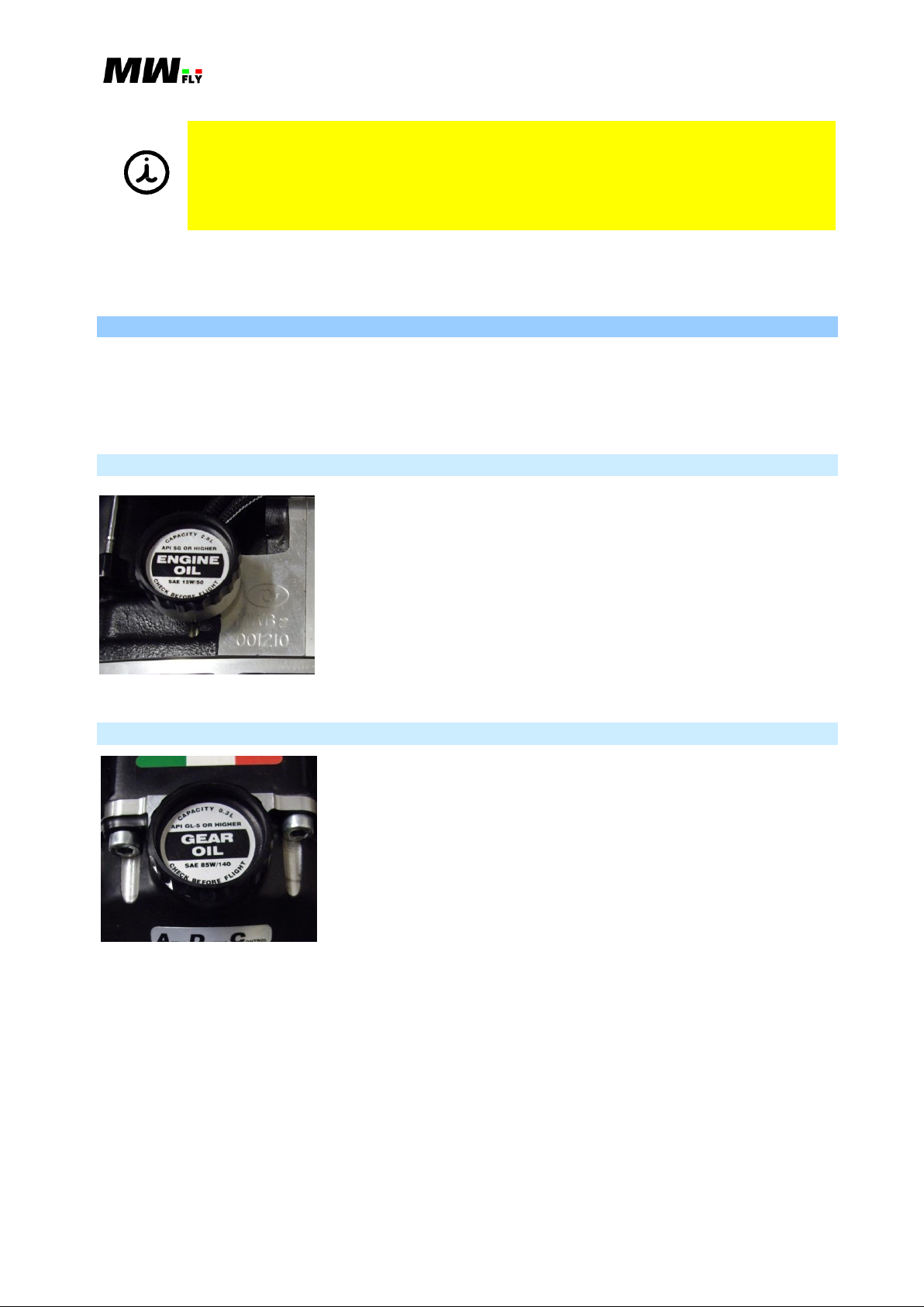
B.3.3.1.P
CAPACITY - 2.8 L
API SG OR HIGHER – this identifies the oil
specification as indicated by the American Petroleum
Institute (API)
ENGINE OIL – engine oil
SAE 15W/50 – oil thermal degree 15W/50 (to select the
correct oil thermal degree for the climate conditions of
the use of the engine refer to the Chapter A.10.3)
CHECK BEFORE FLIGHT
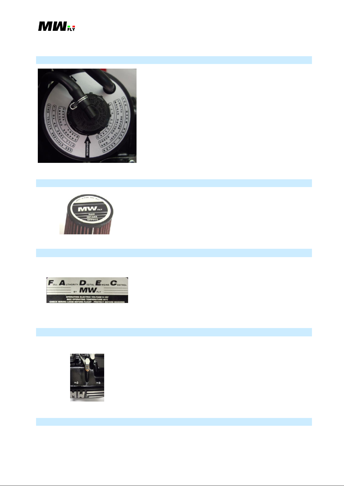
B.3.3.2.P
CAPACITY - 0.3 L
API GL-5 OR HIGHER – this identifies the oil
specification as indicated by the American Petroleum
Institute (API)
GEAR OIL
SAE 85W/140 – oil thermal degree 85W/140
CHECK BEFORE FLIGHT
Where differences exist between this Manual and regulations provided by any authority, the more
stringent regulation should be applied.
B.3.3. Warning labels
There are some warning labels on the engine that indicate the refilling requirements that need to
be done prior to flight as well as other information concerning engine characteristics and
operation. All labels are in English. The following is a list of the labels, their position and
meaning.
B.3.3.1. Engine Oil Filler Cup
B.3.3.2. Reduction Gear Box Oil Filler Cup
Applicable to: B22 and B25 (all versions) Revision 1.3 – 02/24/2015
Manual B – Operations - 15
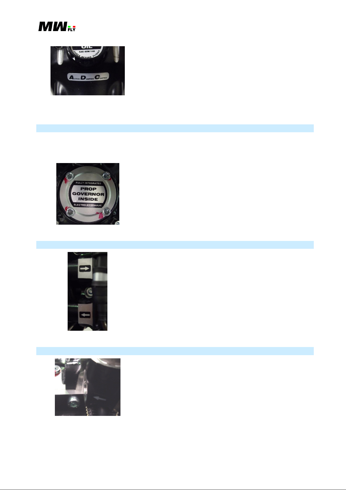
B.3.3.3.P
USE ETHYLENE GLYCOL ONLY –avoid the use of
propylene glycol or just water without ethylene glycol
FILL TANK UP TO 2/3
CHANGE COOLANT EVERY 2 YEARS
RESERVOIR – indicates the expansion tank cup (not
pressurized)
PRESSURIZED – indicates the coolant circuit filler cap
(pressurized)
CAPACITY 0.7 L – Expansion tank capacity
CHECK COOLING SYSTEM AND LEVEL BEFORE
FLIGHT
NEVER OPEN WHEN HOT – this refers to the coolant
circuit pressurized filler cap
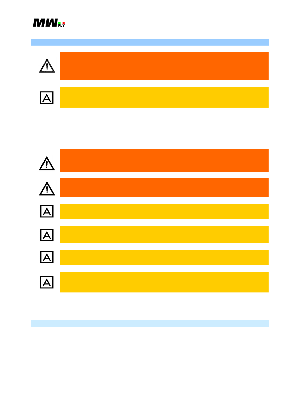
B.3.3.4.P
KEEP CLEAN AND DRY
RAM INTAKE EFFECT – the intake manifold is
designed to take advantage of the “ram effect”
B.3.3.5.P
FULL AUTHORITY DIGITAL ENGINE CONTROL
(F.A.D.E.C.)
OPERATING ELECTRICAL VOLTAGE 9-18V
MAX OPERATING TEMPERATURE 85°C
CHECK WIRING LOOM BEFORE FLIGHT
PROTECT BEFORE WASHING
B.3.3.6.P
CYL1 – Cylinder number 1
CYL2 – Cylinder number 2
CYL3 – Cylinder number 3
CYL4 – Cylinder number 4
This label is not present on the engine model without reduction gear box.
B.3.3.3 Water Expansion Tank
B.3.3.4. Air Filter
B.3.3.5. ECU
This label is placed on the rear side of the ECU‘s bracket.
B.3.3.6. Head Cover
This label, on the engine head cover, indicates the cylinder number as indicated in Chapter B.4.3.
B.3.3.7. Reduction Gear Box
This label is placed on the upper side of the reduction gear box and indicates the Active Damping
Control designed for the AeroPower (B.5.5) family of engines.
Applicable to: B22 and B25 (all versions) Revision 1.3 – 02/24/2015
Manual B – Operations - 16
B.3.3.7.P
ACTIVE DAMPING CONTROL
B.3.3.8.P
PROP GOVERNOR INSIDE
FULLY INTEGRATED ELECTRO-HYDRAULIC
B.3.3.9.P
The arrows are place in correspondence to the in and out
water pump manifold and indicate the direction of the water
flow. The lower manifold is the output line from the engine
to the radiator and the upper manifold is the inlet line from
the radiator to the engine.
B.3.3.10.P
The arrows are placed on the fuel distributor and indicate
the distributor fuel in and out flow. The arrow on side#2
(left side) indicates the inlet line from the fuel pump to the
fuel distributor and the arrow on side#1 (right side)
indicates the outlet return line from the distributor to the
fuel tanks.
This label is not present on the engine version without a reduction gear box.
B.3.3.8. Governor
The engine with reduction gear box can also have an integrated constant speed electro-hydraulic
governor (A.15.1.2.) installed. In this case there is label on the governor oil pump cover on the
front side of the reduction gear box.
B.3.3.9. Water Circuit Arrows
B.3.3.10. Fuel Circuit Arrows
Applicable to: B22 and B25 (all versions) Revision 1.3 – 02/24/2015
Manual B – Operations - 17
Any modification or removal of any part of the engine can cause a dangerous
situation. Substitution of the original parts of the engine with non-original
parts can seriously compromise the technical characteristics of the engine and
its performance.
Any kind of modification, substitution or removal of engine parts not approved by
MW Fly will cause an immediate suspension of the warranty and will release MW
Fly from any liability.
Carefully check that the accessory doesn’t interfere with any part of the
engine that is in motion. Pay particular attention to verify that it doesn’t
interfere with the throttle command or with the propeller.
For no reason modify the engine wiring harness. Do not modify the engine
map of the ECUs.
Avoid installing any accessory that can block the normal coolant flow.
Always check that the total electrical absorption of all the electronic components
installed on the aircraft is not greater than the power supplied by the generator.
It is mandatory to connect each electronic component to the battery supply by using
a fuse (better if a breaker).
The use of non MW Fly original spare parts could compromise the correct
operation of the engine. In this case the guarantee is no longer valid and will
release MW fly from any liability.
B.3.4. Modifications and Accessories
All original MW Fly accessories have been designed and tested to operate with the engine. Since
MW Fly cannot test all of the accessories available on the market so that the operator is
responsible for the choice and installation of the non OEM accessories. Choose an accessory with
respect to the following:
For the installation and the maintenance of the engine, use only the consumables, accessories and
tools indicated at the beginning of each paragraph.
B.3.4.1. Original Accessories
The following is a list of the original accessories available for the A eroP ower engine:
Adapter for bed mounting (cod. S039)
Fuel pump (cod. Q030)
Shock absorber 45Sh (cod. M028), 60Sh (cod. M034), 70Sh (cod. M038), 80Sh (cod. M039)
Standard exhaust system (cod. C075)
Standard radiator kit (cod. C101)
Fuel Delivery Module FD-m (cod. Q050)
Electric Hub Module EH-m (cod. E591)
Applicable to: B22 and B25 (all versions) Revision 1.3 – 02/24/2015

Manual B – Operations - 18
The user is responsible for the risk of not using original accessories and spare
parts. These components can seriously compromise flight safety or change
engine characteristics and performance.
Use only MW Fly original spare parts. These are available to any authorized MW
Fly service center. In case of non-fulfillment the guarantee will not any longer
valid.
Tool ES-m (cod. K472)
Accessories for PVV hydraulic constant speed (cod. C104)
Accessories for governor for constant speed control (cod. C103)
2-Blade Propeller hub for PVV system (cod. C030)
B.3.5. Use of the Technical Documentation
The technical documentation is an essential educational instrument. For complete education it is
necessary to take part in the training courses for the correct installation and use of the engine.
The information given in the engine technical documentation is based on data and experience that
is considered applicable for professionals under normal conditions.
A – Installation Manual: includes all necessary information for the correct installation of the
engine.
B – Operations Manual: includes all the necessary information to correctly operate the engine.
C – Maintenance Manual: includes all the necessary information to correctly execute the
planned maintenance program of the engine.
D – Heavy Maintenance Manual: includes all the information to correctly execute any
unplanned maintenance as the result of an engine failure.
E – Illustrated Parts Catalogue: includes the list of all of the spare parts and accessories.
F – Overhaul Manual: includes all necessary information to carry out a complete overhaul of
the engine because the engine life has reached the TBO, or as a result of a serious failure.
L – Service Letter: includes all the information to upgrade the product or to improve the use
of the engine.
Q – Quick Start Guide: The content is extracted from Manual A
S – Service Bulletin: includes the modifications, control and caution that are required to be
done not later than the date indicated.
X – Alert Service Bulletin: includes all the mandatory modifications, controls and cautions
that must be done before flying.
The rapid technical progress and variations of installation might render present laws and
regulations inapplicable or inadequate.
The illustrations in this Manual are mere sketches and show a typical arrangement. They may not
represent the actual part in all its details but depict parts of the same or similar function. Therefore
deduction of dimensions or other details from illustrations is not permitted.
All necessary documentation is available from the MW Fly Authorized Distributors or their
Service Centers.
Applicable to: B22 and B25 (all versions) Revision 1.3 – 02/24/2015

Manual B – Operations - 19
Name
Model
Version
Power
[CV]
Engine RPM
[rpm]
Prop RPM
[rpm]
B22D
MWB
A
95
3300
3300
B22H
MWB
B
131.5*
4300
---
B22L
MWB
C
114.7
3950
2280
B22R
MWB
D
130.3
4550
2320
B25D
MWC
E
110
3300
3300
B25L
MWC
F
133.1
3950
2280
B25R
MWC
G
154.2
4550
2320
B25H
MWC
H
156*
4300
---
B.4. ENGINE DESCRIPTION
B.4.1. General Characteristics
4 stroke Otto cycle
4 cylinder boxer
Single Over Head Camshaft (SOHC), timing with gears and chain, cam follower and tapper
with valve shim, two valves per cylinder.
Cooling system with a coolant and pump with two different circuits, one for each side of the
engine, expansion tank and thermostat integrated on the engine. All cooling circuit pipes are
stainless steel.
Forced lubrication with internal gear (geretor) pump, semi-dry sump without external pipe.
Mapped ignition f(RPM,MAP), with inductive coil, with dwell time mapped f(VBATT) and
ignition correction f(engine temperature)
Mapped fuel injection f (RPM,MAP), with correction f(engine temperature, air temperature)
Data transmission from the ECUs to EMS system on CAN bus
Fuel system with an electric fuel pump controlled by the ECUs, and an auxiliary electric fuel
pump, the fuel circuit is done with steel pipe, and the fuel pressure regulator is integrated in
the fuel circuit
The reduction gear box uses specific oil that is separate from the engine oil, it has a helical
gear and monolithic propeller shaft, and it is designed for an oil pump for the hydraulic
constant speed governor.
ADC (Automatic Damping Control) to control the torsional vibration up to 2500 rpm
Electric starter motor and start relay pre-installed on the engine
Oil cooled alternator and voltage regulator pre-installed on the engine.
B.4.2. Engine Models
The following table summarizes the main features of the A eroPower family of engines.
Next to the name is shown the model and the respective version, which appears in the
identification code shown on the top of each engine. (see picture B.2.3.1.P).
B.4.2.1.C
* Data refers to the version without reduction gear box
The B22H and B25H models are available with or without a reduction gear box. In the second
case the performance is reduced by 5%.
All of the engine models can be supplied with a pre-installed EMS kit which includes sensors and
cables for any EFIS and EMS instrumentation with a CAN line available to receive the data from
the ECUs. For more detail see paragraph A.16.1.
Applicable to: B22 and B25 (all versions) Revision 1.3 – 02/24/2015

Manual B – Operations - 20
ULL
UTHORITY I GITAL NGINE ONTROL
FLYBY
MAX OPERATING TEMPERATURE 85°C
CHECK WIRING LOOM BEFORE FLIGHT -
OPERATING ELECTRIC VOLTAGE 9-18V
PROTECT BEFORE WASHING
RESERVOIR
PRESSURIZED
N
E
V
E
R
O
P
E
N
W
H
E
N
O
T
H
C
A
P
A
C
I
T
0
.
Y
7
L
U
S
E
E
T
H
Y
L
E
N
E
E
C
H
A
N
G
E
C
O
O
L
A
N
T
V
E
R
Y
2
Y
E
A
R
S
E
C
E
A
H
C
O
C
K
I
L
O
N
S
T
E
L
D
N
O
F
E
B
E
R
T
H
G
I
L
F
G
S
Y
M
L
E
V
G
L
Y
C
L
O
O
N
Y
L
F
A
T
L
L
I
O
T
P
U
K
N
/
3
2
API SG OR HI GHER
C
H
E
C
B
I
F
O
R
E
F
L
G
H
T
K
E
GE A R
SAE 15W/50
T
I
C
A
P
A
C
8
.
2
Y
L
OI L
API SG OR HI GHER
C
H
E
C
B
I
F
O
R
E
F
L
G
H
T
K
E
EN G IN E
SAE 15W/50
T
I
C
A
P
A
C
8
.
2
Y
L
OI L
#1
#2
#3
#4
side #1
Side # 2
The EMS is not integrated in the engine identification code, because that option is available for all
of the engines as an aftermarket kit.
B.4.3. Cylinder Numeration and Position
The cylinders are numbered in the same order that they fire. From a top view of the engine (as
show in picture B.4.3.1.P), cylinder #1 is on the top left, cylinder #2 is on the bottom left, cylinder
#3 is on top right and cylinder #4 is on the bottom right. The same criterion is used to number the
sides of the engine; cylinder #1 and #2 are on side #1 and cylinder #3 and #4 are on side #2.
To know the position of all components of the engine see paragraph A.4.3.
Applicable to: B22 and B25 (all versions) Revision 1.3 – 02/24/2015
B.4.3.1.P

Manual B – Operations - 21
If not specified, the data refers to all engine models.
For safe use of the engine, always respect the operation limits and the
prescribed maintenance time table.
It is not possible to extend the guarantee condition for different uses of the engine.
MW Fly declines any responsibility for damage or bodily injury due to the
improper end use of the engine.
An improper end use of the engine will cause an immediate suspension of the
guarantee and will release MW fly from any liability.
The engine life cannot exceed the TBO limit (see table C.5.2.1.C): when the engine
reach the TBO limit it’s mandatory a complete overhaul check of the engine that
should be done only by an MW Fly authorized service center.
For engine safety it’s important to install and operate in correct way. It important to
use the instrumentation to control that all the engine parameters indicated in the
paragraph A.9.2, are in the operating limit in any working condition.
B.5. TECHNICAL CHARATERISTICS
B.5.1. End Use
B
22
and B25 AeroPo wer engines have been designed to equip ULM, Experimental
and LSA aircraft, two or three axis, with power requirements that conform to the power delivered
by the engine.
AeroPower engines are designed exclusively for recreational purposes in installations where
a sudden stoppage of the engine does not compromise flight safety.
Applicable to: B22 and B25 (all versions) Revision 1.3 – 02/24/2015
Manual B – Operations - 22
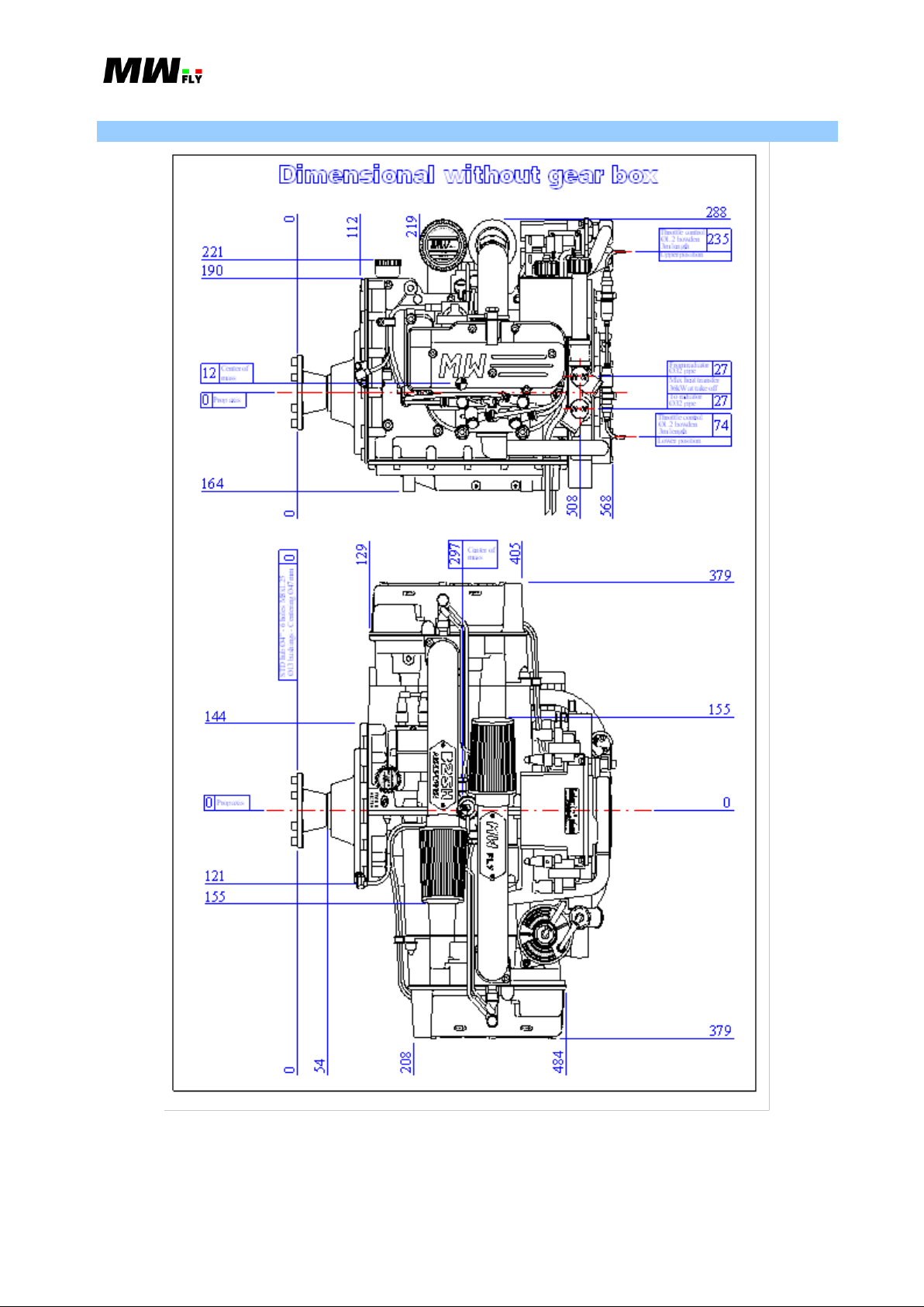
B.5.2. Dimension
Applicable to: B22 and B25 (all versions) Revision 1.3 – 02/24/2015
B.5.2.1.P

Manual B – Operations - 23
Ø13 bushings - Centering Ø47mm
STD hub Ø4" - 6 holes M8x1.25
0
209
144
121
84
0
Prop axis
OI LO IL
L
F
SAE 85W/ 140
ONTROL
T
H
G
I
AMPINGCTIVE
C
E
K
R
O
F
B
E
C
E
H
.
3
GE A RGE A R
API GL-5 OR HIGHER
L
A
P
A
C
I
T
0
Y
C
98
L
Y
C
Y
O
O
L
N
PRESSURIZ ED
560
284
3CYL CY L 4
C
E
K
C
D
O
L
C
L
E
E
V
R
V
E
E
P
O
7
L
T
O
L
I
I
Y
0
N
G
W
N
E
H
O
R
E
F
B
E
S
N
.
F
Y
M
E
L
S
T
O
H
T
I
G
H
T
G
E
K
Y
A
E
RESERVOIR
N
P
H
A
C
C
A
E
N
S
U
N
H
T
T
E
E
L
Y
A
E
N
R
E
H
C
F
I
L
A
V
N
G
E
L
S
/
L
O
A
L
O
R
A
E
Y
C
U
P
T
O
2
N
2
T
3
379
C
A
P
A
L
2
.
8
E
OI LO IL
SAE 15W/50
API SG OR HIGHER
EN G IN EE NG IN E
T
F
G
L
F
E
R
I
O
H
C
K
B
C
E
H
C
I
Y
T
CHECK WIRIN G LOOM BEFORE FLIGHT -PROTECT BEFORE WASHINGPROTECT BEFORE WASHING
MAX OPERATING TEMPERATURE 85°C
OPERATING ELECTR IC VOLTAGE 9-18V
FLY
ONTROLNGINE
BY
IGITALUTHORITYU LL
0
209
Dimensional w ith gear box
68
0
247
0 0
205
Center of
mass
Prop axis
88
107
0
188
mass
Center of
1CYL
371
481
CY L 2
644
584
379
Throttle control
Lower position
3m length
Ø1.2 bowden
Max heat transfer
34.5kW at take off
157
110
To radiator
Ø32 pipe
56
Prop axis
Ø32 pipe
From radiator
0
D
C
P
N
295
EFFECT
INTAKE
RAM
E
K
E
Y
FL Y
R
D
A
L
E
N
A
3m length
Upper position
Throttle control
Ø1.2 bowden
151
204
Applicable to: B22 and B25 (all versions) Revision 1.3 – 02/24/2015
B.5.2.2.P

Manual B – Operations - 24
Max dimension [mm]
direction -
direction +
Total
Max along X axis
10
644 (568*)
654 (578*)
Max along Y axis
379
379
758
Max along Z axis
247 (164)
204 (288)
451
Weight [Kg]
Dry
With lubricants
B22D/B25D
79.5
82.3
B22H*/B25H*
78.7
81.5
B22L/B25L
83.6
86.6
B22R/B25R
83.6
86.6
Adapter for bed mount (4 pieces)
0.37 Kg
Exhaust system
~ 5.1 Kg
Coolant radiator kit
~ 1.7 Kg
Auxiliary fuel pump
0.66 Kg
Governor**
~0.5 Kg
Propeller with hub **
---
Instrument ES-m (without wiring
loom)**
---
EH-m (Electric Hub Module)
~ 0.98 Kg
FD- m (Fuel Delivery Module)
~ 2.75 Kg
The value and the graph of the present chapter indicate the engine performance
with 15°C of air temperature and at sea level (1013 mbar) and with 0% of humidity
(condition ISA-International Standard Atmosphere).
Maximum Dimensions of the Engine
B.5.2.1.C
* model without reduction gear box
The tolerance on these dimensions is ±1 mm.
B.5.3. Weight
Table B.5.3.1.C shows the dry weight of the engine and the weight with lubricants. The weight
includes all the accessories needed to fly (internal generator, voltage regulator, starter relay,
thermostat, water expansion tank, throttle control, fuel injection wiring loom, two ECU’s, rubber
mounting, air filter). Only the radiator coolant and exhaust system are not included in the weight
shown in the table.
B.5.3.1.C
* Model without reduction gear box; with the reduction gear box the weight is 83.6 and 86.6.
B.5.3.1. Optional Accessory Weight
** Data not available
B.5.4. Performance
Applicable to: B22 and B25 (all versions) Revision 1.3 – 02/24/2015
Manual B – Operations - 25
B22 Version
Power [HP (kW)]
B22D
B22H*
B22L
B22R
Take off (max for 5 minutes)
@rpm
95 (69.8)
@3400
131.5 (96.7)
@4300
114.7 (84.3)
@3950
130.3 (95.8)
@4550
max continuous
@rpm
82 (60.3)
@3320÷3400
112.5 (82.7)
@4300
98 (72)
@4010÷4200
110 (80.9)
@4420÷4700
Smaller specific consumption
@MAP[inHg]
64 (47.1)
@24
92.5 (68)
@25.6
84.5 (62.1)
@25.6
96.5 (70.9)
@25.7
B25 Version
Power [HP (kW)]
B25D
B25H*
B25L
B25R
Take off (max for 5 minutes)
@rpm
110 (80.8)
@3400
156 (114.6)
@4300
133.1 (97.9)
@3950
154.2 (113.4)
@4550
max continuous
@rpm
95 (69.8)
@3330÷3400
133.5 (98.1)
@4300
115 (84.5)
@4070÷4200
132 (97)
@4500÷4700
Smaller specific consumption
@MAP[inHg]
74.2 (54.5)
@24
111.5 (82)
@25.7
98.5 (72.4)
@25.7
116 (85.3)
@25..8
During flight the preferred power is set with high RPM and low MAP.
The use of the engine at maximum continuous power for a long period can
seriously damage the engine and can cause a sudden stoppage of the engine.
B.5.4.1.C
* Data refers to the engine model without reduction gear box
B.5.4.2.C
* Data refers to the engine model without reduction gear box
The use of the engine at maximum power is only allowed for 5 minutes continuous. The
maximum continuous power is a function of the MAP and RPM: the limit at high RPM is due to
the thermodynamics; the limit at low RPM is to avoid overload on the reduction gear box.
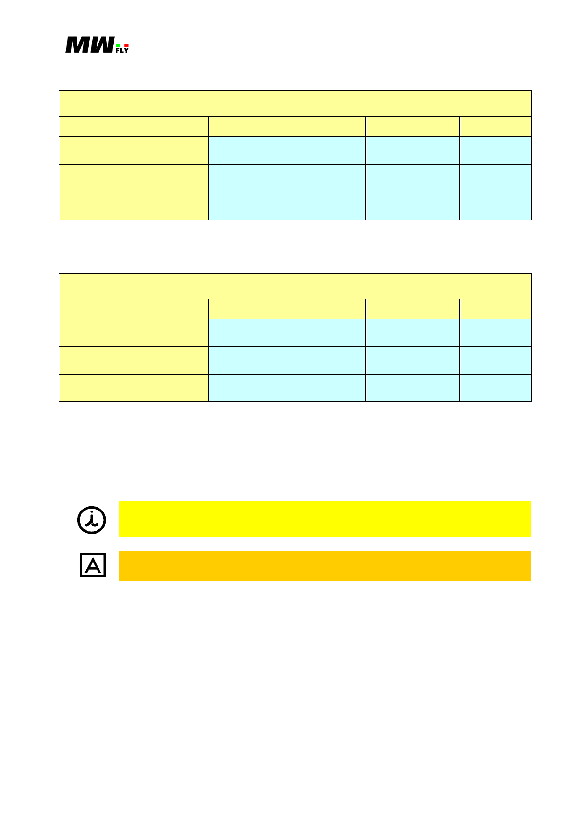
In the following paragraph there is the performance graph for each engine model:
Graph POWER/RPM and TORQUE/RPM: this is the maximum power and the maximum
torque with the engine at full throttle in function of RPM.
Graph NECESSARY POWER/AVAILABLE POWER: this is the range of use of the engine,
(the area between the two graphs), the graph of the available power, is the power output of the
engine, the necessary power is the power that is required to keep the speed of the propeller
constant (a propeller that makes the engine run at maximum RPM limit and not over). The
graph also indicates, in bold, the maximum continuous power.
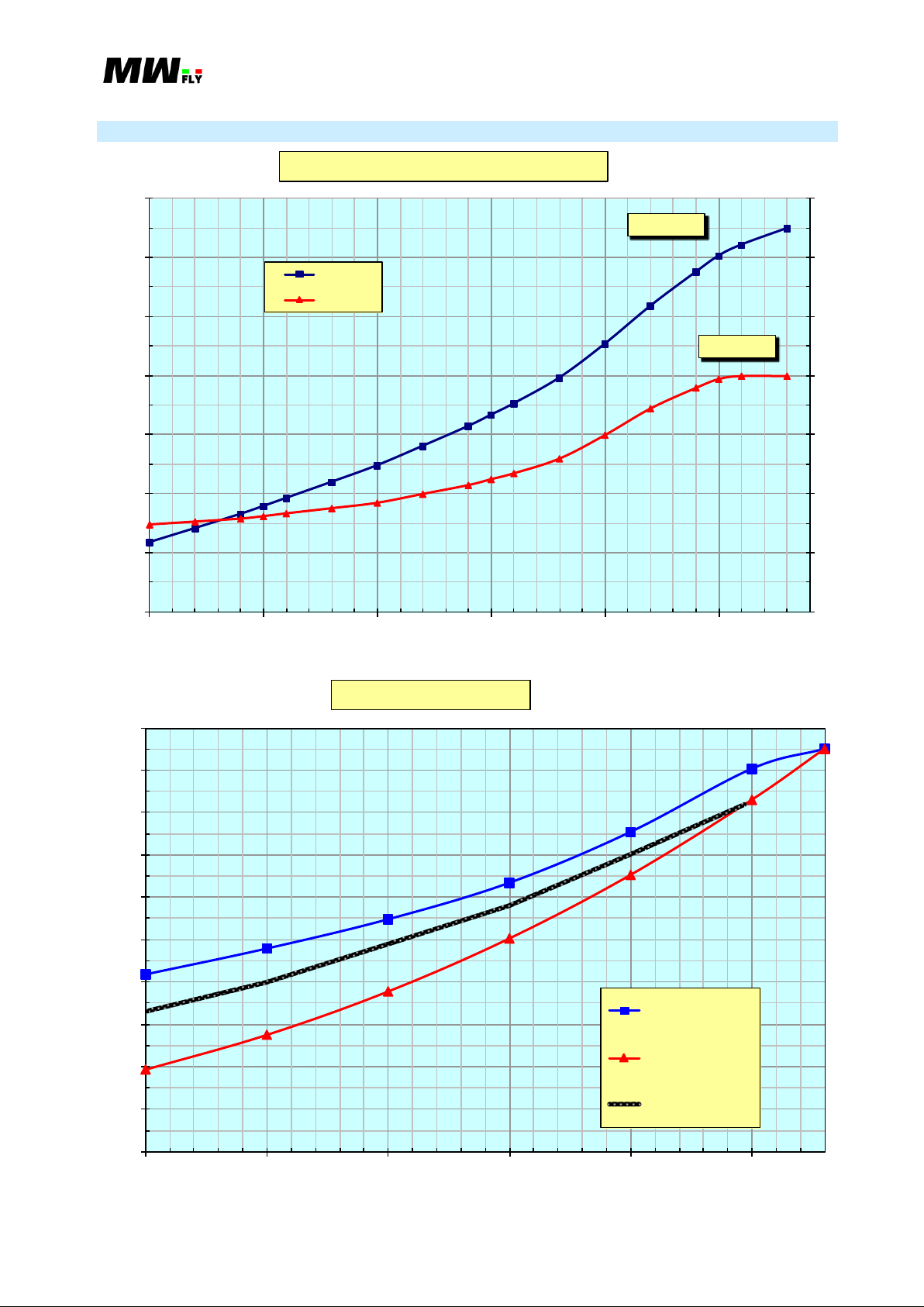
Graph POWER/RPM with constant MAP: each graph refers to a different value of MAP as
indicated in inches of mercury (inHg) and indicates the power in function of the RPM. The
bold indicates the maximum continue power in function of the RPM.
Applicable to: B22 and B25 (all versions) Revision 1.3 – 02/24/2015

Manual B – Operations - 26
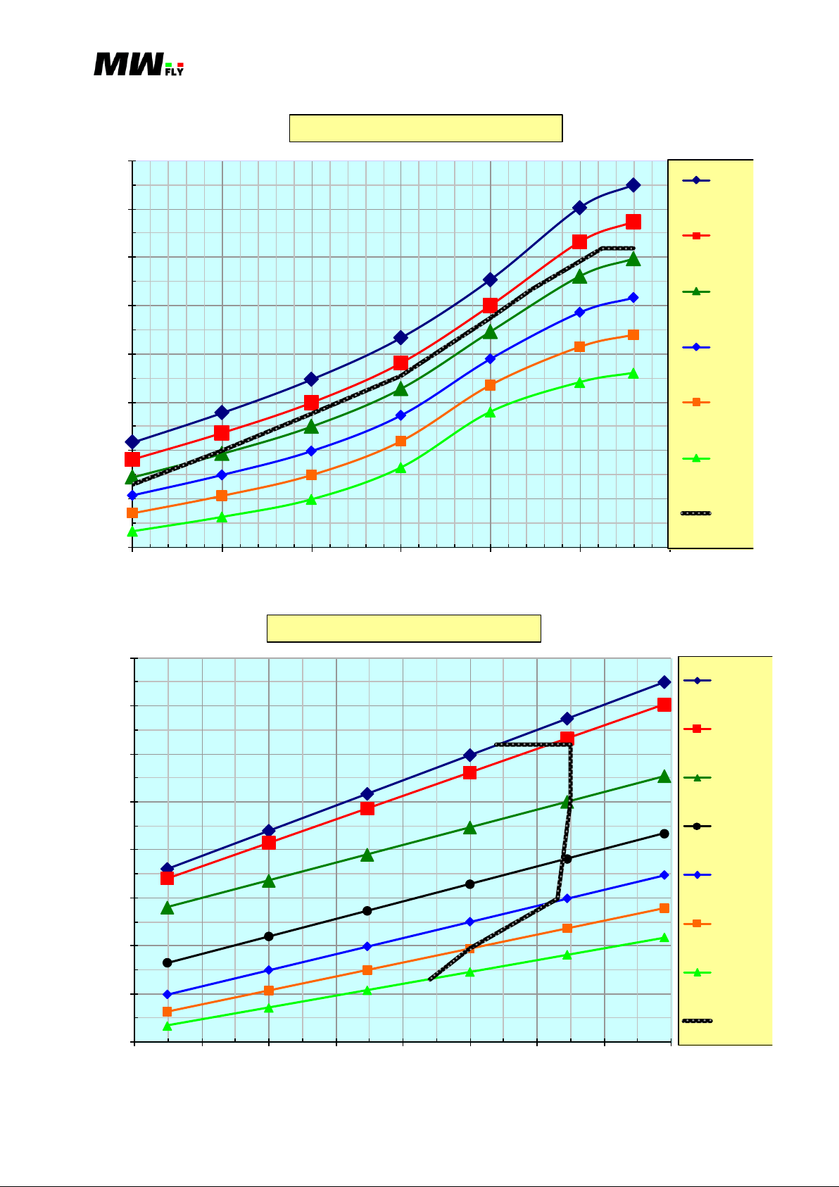
5% difference from the graph is permitted.
Graph POWER/MAP with constant RPM: each graph indicates the power output in reference
to the different values of RPM in function of MAP. The bold indicates the maximum
continuous power in function of the MAP.
Applicable to: B22 and B25 (all versions) Revision 1.3 – 02/24/2015
Manual B – Operations - 27
B.5.4.1. B22D
20@3400
95@3400
12
14
16
18
20
22
24
26
30
40
50
60
70
80
90
100
2000 2250 2500 2750 3000 3250
[HP]
[Kgm]
[RPM]
B22D Performance @ full throttle
Power
Torque
0
10
20
30
40
50
60
70
80
90
100
2000 2250 2500 2750 3000 3250
[HP]
[RPM]
Range of use B22D
Available power
Necessary power
Max cont. power
B.5.4.3.C
Applicable to: B22 and B25 (all versions) Revision 1.3 – 02/24/2015
B.5.4.4.C
Manual B – Operations - 28
20
30
40
50
60
70
80
90
100
2000 2250 2500 2750 3000 3250 3500
[[HP]
[RPM]
B22D Power @ constant MAP
29.9
28.5
27
25.5
24
22.5
max
cont.
20
30
40
50
60
70
80
90
100
22 23 24 25 26 27 28 29 30
[HP]
[inHg]
B22D Power @ constant RPM
3400
3250
3000
2750
2500
2250
2000
max cont.
B.5.4.5.C
Applicable to: B22 and B25 (all versions) Revision 1.3 – 02/24/2015
B.5.4.6.C
 Loading...