

Manual B – Operations - 1
Manual B
OPERATIONS MANUAL
B22
B25
Applicable to: B22 and B25 (all versions) Revision 1.3 – 02/24/2015
AeroPower
AeroPower

Manual B – Operations - 2
Before attempting any engine start carefully read Manual A containing
important safety information. Not following safety procedures could cause
severe injury or loss of life. Consult the aircraft instruction manual for more
information on safety.
All information, illustrations, instructions and technical data contained in this manual has been upgraded
before printing. MW Fly reserves the right to modify, correct or upgrade general data at any time without any
obligation or prior consent from third parties. Publication of any part of this document without written consent
of MW Fly is strictly prohibited.
This Manual forms part of the engine and must be kept safe. It must accompany the engine in case of sale to a
new owner. The original document is written in Italian and this language will be used to settle any dispute of a
legal or technical nature.
Applicable to: B22 and B25 (all versions) Revision 1.3 – 02/24/2015

Manual B – Operations - 3
B.1. SUMMARY 7
B.2. INTRODUCTION 7
B.2.1. Statement 7
B.2.2. Consultation Notes 7
B.2.3. Identification Data 9
B.2.4. MW Fly Authorized Service Centers 9
B.3. SAFETY 10
B.3.1. Statement 10
B.3.2. Safety Elements 10
B.3.2.1. Passive Safety 10
B.3.2.2. Active Safety Elements 12
B.3.3. Warning labels 14
B.3.3.1. Engine Oil Filler Cup 14
B.3.3.2. Reduction Gear Box Oil Filler Cup 14
B.3.3.3 Water Expansion Tank 15
B.3.3.4. Air Filter 15
B.3.3.5. ECU 15
B.3.3.6. Head Cover 15
B.3.3.7. Reduction Gear Box 15
B.3.3.8. Governor 16
B.3.3.9. Water Circuit Arrows 16
B.3.3.10. Fuel Circuit Arrows 16
B.3.4. Modifications and Accessories 17
B.3.4.1. Original Accessories 17
B.3.5. Use of the Technical Documentation 18
B.4. ENGINE DESCRIPTION 19
B.4.1. General Characteristics 19
B.4.2. Engine Models 19
B.4.3. Cylinder Numeration and Position 20
B.5. TECHNICAL CHARATERISTICS 21
B.5.1. End Use 21
B.5.2. Dimension 22
B.5.3. Weight 24
B.5.3.1. Optional Accessory Weight 24
B.5.4. Performance 24
B.5.4.1. B22D 27
B.5.4.2. B22H 29
B.5.4.3. B22L 30
B.5.4.4. B22R 32
B.5.4.5 B25D 34
B.5.4.17.C 34
Applicable to: B22 and B25 (all versions) Revision 1.3 – 02/24/2015

Manual B – Operations - 4
5
10
15
20
25
30
35
40
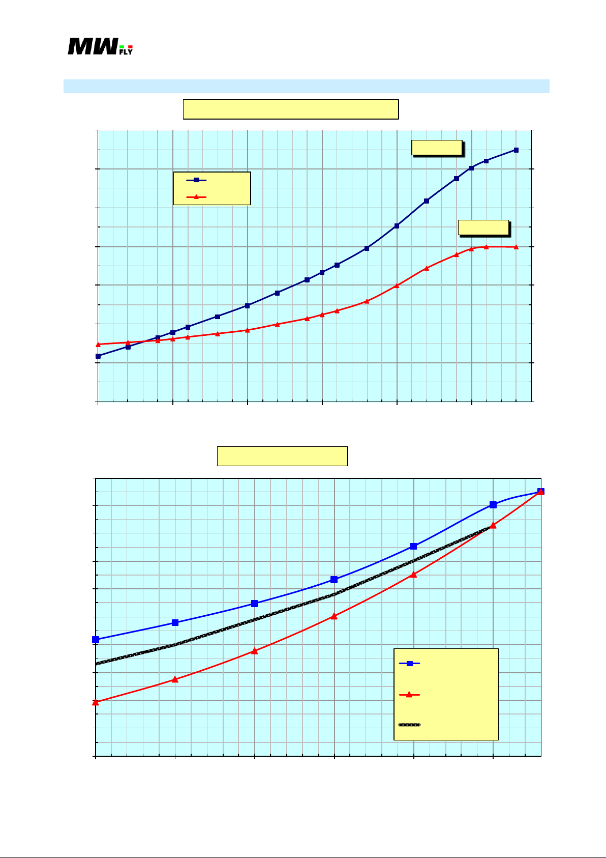
2000 2250 2500 2750 3000 3250 3500 3750 4000 4250
[L/h]
[RPM]
B25L Consumption @ constant MAP
29.9
28.5
27
25.5
24
22.5
B.5.4.6. B25H 36
B.5.4.7. B25L 37
B.5.4.8. B25R 39
B.5.4.9. Performance Variation 41
B.5.5. Ratio Power/Weight 42
B.5.6. Fuel Consumption 42
B.5.6.1. B22D 44
B.5.6.2. B22H 46
B.5.6.3. B22L 47
B.5.6.4. B22R 49
B.5.6.5. B25D 51
B.5.6.6. B25H 53
B.5.6.7. B25L
54
B.5.6.8. B25R 56
B.5.7. Propeller speed 58
B.5.8. Direction of the Rotation of the Propeller 58
B.6. DESCRIPTION OF THE SYSTEMS 60
B.6.1. Cooling system 60
B.6.2. Lubricant system 61
B.6.3. Fuel system 62
B.6.4. Electric system 63
B.6.4.1. ES-m Instrumentation 64
Applicable to: B22 and B25 (all versions) Revision 1.3 – 02/24/2015

Manual B – Operations - 5
B.7. OPERATING INSTRUCTION 65
B.7.1. Operating limits 65
B.7.1.1. RPM 65
B.7.1.2. Fuel Pressure 66
B.7.1.3. Engine oil pressure 66
B.7.1.4. Engine Oil Temperature 67
B.7.1.5. Reduction Gear Box Oil Temperature 67
B.7.1.6. Coolant Temperature 68
B.7.1.7. Air Intake Temperature 68
B.7.1.8. Load Factor 69
B.7.1.9. Inclination Angle 69
B.7.1.10 Electrical Voltage 70
B.7.2. Operative Fluid 70
B.7.2.1. Cooling Fluid 70
B.7.2.2. Engine Oil 70
B.7.2.3. Reduction Gear Box Oil 71
B.7.2.4. Fuel 71
B.7.3. General Criteria to Operate the Engine 72
B.7.3.1. Check Before Start 72
B.7.3.2. Start Operation 75
B.7.3.3. Engine Warm Up 76
B.7.3.4. Before Take Off 77
B.7.3.5. Take Off 78
B.7.3.6. Cruise 78
B.7.3.7. Landing 78
B.7.3.8. Engine Switch off 79
B.7.3.9. Use of the Engine in Winter Season 79
B.7.4. Behavior in Case of Emergency 81
B.7.4.1. Accidental Engine Stop – Start During Flight 81
B.7.4.2. Over Rev 81
B.7.4.3. Exceeding the Maximum Coolant Temperature 81
B.7.4.4. Exceeding the Maximum Oil Temperature 82
B.7.4.5. Oil Pressure Below the Limit in Flight 82
B.7.4.6. Oil Pressure Below the Limit on the Ground 82
B.7.4.7. Fuel Pressure Below the Limit in Flight 82
B.7.4.8. Fuel Pressure Below the Limit on the Ground 83
B.7.4.9. Battery Voltage Over the Limit 83
B.7.4.10. Battery Voltage Below the Limit 83
B.7.4.11. ECU Alarm 84
B.7.4.12. Generator Alarm 84
B.7.4.13. Abnormal Vibration 84
B.7.4.14. Irregular Operation 85
Applicable to: B22 and B25 (all versions) Revision 1.3 – 02/24/2015

Manual B – Operations - 6
B.8. ENGINE CONTROL 86
B.8.1. List of Tool Kit for the Pre-flight Checks or Emergency 86
B.8.2. Shelter from Service for Extended Period of Time 86
B.8.3. Return to Service After Long Inactivity 86
B.8.4. Engine Protection When Used in Cold Climates 87
B.9. MALFUNCTION RESOLUTION 88
B.9.1. Operation Malfunctions and Their Resolution 88
B.9.2. Anomalies to the Injection and Ignition Systems 89
B.9.3. Signal Engine Malfunction 90
B.10. AUTHORIZED DISTRIBUTOR 92
B.11. MANUAL UPDATE LIST 93
Applicable to: B22 and B25 (all versions) Revision 1.3 – 02/24/2015

Manual B – Operations - 7
This engine has not received any certification for aeronautical use.
It must be used exclusively on experimental aircraft where an engine failure
will not compromise flight safety. Its use in cetified aircraft is strictly
prohibited.
Operate the engine in compliance with the local rules and laws.
B.1. SUMMARY
B.2. INTRODUCTION
The A eroPower series of engines are designed and manufactured using the most modern
motor technology with the purpose of achieving good performance combined with a high level of
passive safety. If the engine is used correctly it will return years of pleasure and reliable service.
Please read this manual carefully before using the engine and apply all safety standards contained
in it, in addition to those that your experience and common sense suggest.
Remember that regular maintenance and careful inspection of the engine before flight are essential
safety factors.
MW Fly will be happy to provide additional information and all the technical support you will
need.
B.2.1. Statement
The purpose of this operations manual is to provide the users of the AeroPower engine
family with the basic operating instructions and safety information. Prior to commencing to
operate the engine it is crucial to read and understand the contents of this document. If any part of
this manual is unclear or there are any doubts on the interpretation, contact an MW Fly service
center.
For additional or more detailed information consult the Maintenance Manual and the Additional
Maintenance Manual.
It is fundamental to integrate the information of this manual with the safety precautions of the
aircraft manufacturer and with safety conditions from your personal experience.
B.2.2. Consultation Notes
This manual was originally printed in Italian. This will be the only language used for any
reference or dispute.
This manual is divided into sections, chapters and paragraphs. The paragraphs could be partitioned
into one or more topics. The title of each section, chapter and paragraph is indicated as follows:
SECTION
Chapter
Paragraph
Topic
Applicable to: B22 and B25 (all versions) Revision 1.3 – 02/24/2015
Manual B – Operations - 8
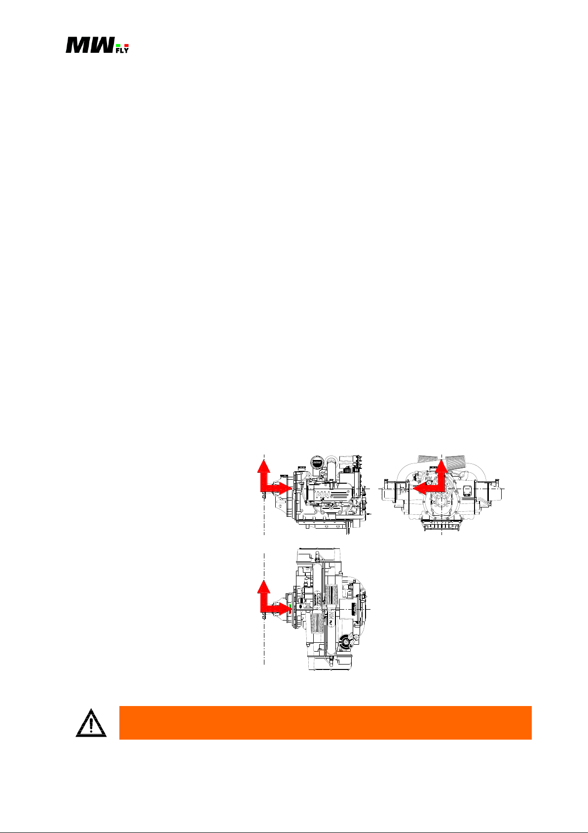
A 3D Cartesian coordinate
right hand is used in the
present manual. The axis
origin is on the propeller shaft.
In the intersection with the
propeller level on the propeller
flange, the x-axis positive
direction is towards the engine
(see picture B.2.2.1.P), the yaxis positive direction is
towards side #1, the z-axis
points up.
RAM
INTAKE
EFFECT
E
C
L
P
E
K
E
Y
D
N
A
D
R
FLY
A
N
T
S
G
S
Y
N
E
B
T
H
O
H
G
H
E
N
E
R
L
F
P
E
N
W
O
F
I
O
T
G
L
T
H
L
L
I
RESERVOIR
R
C
D
N
N
E
V
E
A
U
S
E
F
E
L
E
0
.
Y
7
A
P
A
C
I
O
C
I
L
O
L
E
T
E
H
C
E
C
K
L
V
M
O
L
A
N
T
O
T
/
2
N
E
P
U
K
N
O
3
Y
L
E
N
G
V
E
R
Y
2
C
E
H
A
E
C
Y
E
A
R
S
A
T
PRESSURIZED
Y
L
O
O
N
Y
C
L
PROTECT BEFORE WASHING
ONTROLUTHORITY
MAX OPERATING TEMPERATURE 85°C
CHECK WIRING LOOM BEFORE FLIGH T -
OPERATING ELECTRIC VOLTAGE 9-18V
NGINEIGITAL
FLY
ULL
BY
API GL-5 OR HIGHER
C
H
E
C
B
I
F
O
R
E
F
L
G
H
T
K
E
SAE 85W/140
T
I
C
A
P
A
C
3
.
0
Y
L
CTIVE AMPING ONTROL
GEAR
OIL
API SG OR HIGHER
C
H
E
C
B
I
F
O
R
E
F
L
G
H
T
K
E
SAE 15W/50
T
I
C
A
P
A
C
8
.
2
Y
L
ENGI NE
OIL
Z
X
Y
X
Y
Z
WARNING: Not following this instruction can cause severe personal injury or
loss of life.
B.2.2.1.P
The numeration is an alpha-numeric code that follows format below:
B.7.1.8.
The first letter indicates the type of manual:
A = installation manual
B = operations manual
C = maintenance manual
D = heavy maintenance manual
The first number (between the first and second dot): this number (one or two digits) indicates
the section.
The second number (between the second and third dot): this number (one or two digits)
indicates the chapter.
The third number (between the third and fourth dot): this number (one or two digit) indicates
the paragraph and is not always present.
The numeration of the pictures follows the same criteria for the first three parts of the code. The
third number is the number of the picture in the chapter. A letter P is added at the end of the code.
(e.g. B.5.8.2.P).
The numeration of the tables follows the same criteria for the first three parts of the code. The
third number is the number of the picture in the chapter. A letter C is added at the end of the code.
(e.g. B.5.8.2.C).
Specifications are given in the ST metric system (C.2.4.); in the table the measurement units are
indicated between square brackets [].
Symbols used in this manual have the following meaning:
Applicable to: B22 and B25 (all versions) Revision 1.3 – 02/24/2015
Manual B – Operations - 9
CAUTION: Not following this instruction could cause severe damage to the engine
or other components and possible engine failure.
NOTE: Refers to supplementary information to better understand or execute an
instruction.
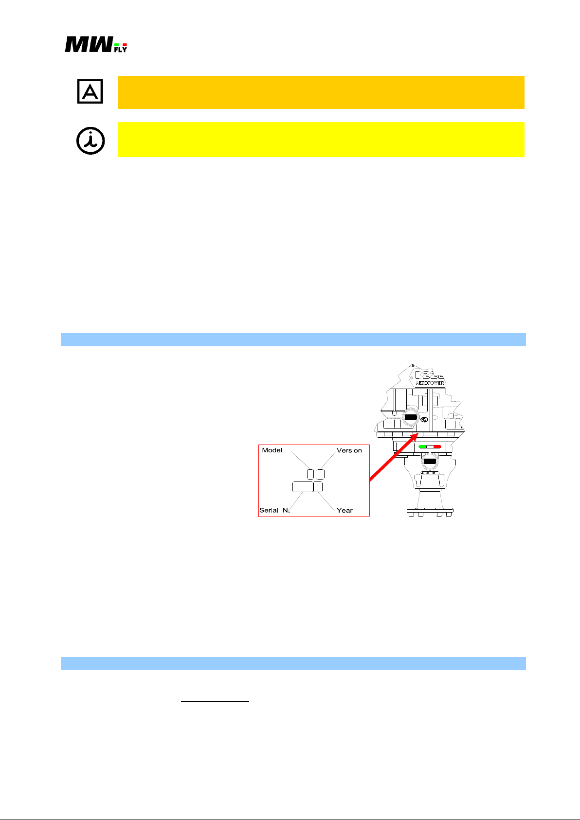
The Engine serial number is
located on the upper side of
crank case near oil dip stick.
It is composed of ten alpha
numeric codes where the third
and fourth symbol indicate
Model and Version, the
following four are the serial
number and the last two are
the year of manufacturing.
Identification code and
version is illustrated in chart
B.4.2.1.C.
API GL-5 OR HIGHER
C
H
E
C
B
I
F
O
R
E
F
L
G
H
T
K
E
SAE 85W/14 0
T
I
C
A
P
A
C
Y
3
.
0
GE A R
L
CTIVE AMPI NG ONTROL
OI L
API SG OR HI GHER
C
H
E
C
B
I
F
O
R
E
F
L
G
H
T
K
E
SAE 15W/50
T
I
C
A
P
A
C
8
.
2
Y
L
EN G IN E
OI L
B.2.3.1.P
1., 2., … This numbering is used to list tools and consumables needed to run an installation or
maintenance; it is also used to bring in parts lists or engine parts shown in the
illustrations.
a., b., … This numbering is used to indicate a list of actions or subjects with relation to inclusion:
all of the actions or options listed must be verified.
o This symbol is used to indicate a list of actions or subjects with relation to exclusion: only one
of the actions or options listed with this symbol must be verified.
This symbol is used to list the general characteristics of the engine, component specifications
or options for installation or maintenance.
B.2.3. Identification Data
The relationship between the engine serial number and the engine model is indicated in the table
B.4.2.1.C.
Deleting or modifying the serial number will revoke any warranty and obligation by MW Fly
toward current owner.
Provide the serial number on any request for an engine part or technical information.
B.2.4. MW Fly Authorized Service Centers
Contact the nearest service centre or web-site for any information regarding service, maintenance
or spare parts. (B.10. or www.mwfly.it).
Applicable to: B22 and B25 (all versions) Revision 1.3 – 02/24/2015

Manual B – Operations - 10
B.3. SAFETY
B.3.1. Statement
Just by reading this manual will not eliminate the hazards connected to the installation and use of
the engine. However the understanding and application of the information herein is essential for a
proper and safe use of the engine.
The information, components, system descriptions, pictures, tables and technical data contained in
the present manual are correct at the time of publication. MW Fly, however, maintains a policy of
continuous improvement of its products without imposing upon itself any obligation to install
them on its products previously manufactured.
The onus to install MW Fly B22 engine is at the sole discretion and responsibility of the Original
Manufacturer, Home Builder or Aircraft Owner. MW Fly cannot assume responsibility for a
successful installation in a specific airframe due to the variety of designs existing in the market.
For this reasons MW Fly declines responsibility regarding damage to engine parts, accessories or
aircraft structure during the installation and use of this engine. The owner accepts the
responsibility and the risk in using this engine.
MW Fly reserves the right at any time to discontinue or change specifications, designs, features,
models or equipment without incurring obligation. It is forbidden to copy any part of the present
manual without authorization from MW Fly.
B.3.2. Safety Elements
It very important to understand all the safety aspects and to distinguish the two different safety
types; active and passive.
B.3.2.1. Passive Safety
Passive safety concerns the engine design and the engine installation criteria. The following is a
list of the main engine features designed to increase passive safety.
CRANK SHAFT ON BALL BEARINGS: This reduces the risk of engine stoppage in case of
lubricant system default or oil leakage. Moreover, unexpected wearing of the bearings is easy
to identify because it is characterized by a clear increase in noise on the lower side of the
crank case. Plain bearings do not provide any clear signal in case of unexpected wearing.
MONOLITIC CONNECTING ROD: This reduces the risk of the default of the crank that is
often connected to the wrong installation of the rod cup.
MACHINED PISTON: This increases the safety by avoiding the risk of deformation due to
intrusion in the fusion, press residual stress, and use of low thermal dilatation coefficient
alloy.
SINGLE OVER HEAD CAMSHAFT (SOHC): By using this it is not necessary to adopt
hydraulic tappets (that are necessary with a push rod system) and it avoids the risk of breaking
the valve in case of a drop in oil pressure. Moreover, the use of SOHC reduces the dynamic
load on the timing command thereby reducing the friction and the wear of the timing
mechanical parts.
REDUCTION GEAR BOX WITH SEPARATE LUBRICATION: The use a specific oil for
the reduction gear box increases the reliability and reduces the risk of a fatigue fracture and
pitting wear of the teeth.
MONOLITIC PROPELLER SHAFT: This reduces the risk of a fatigue fracture of the
propeller shaft and also increases its strength.
Applicable to: B22 and B25 (all versions) Revision 1.3 – 02/24/2015

Manual B – Operations - 11
ELECTRO-HYDRALIC DAMPING SYSTEM (ADC): This system avoids the use of a
mechanical damping system that is a component that is subject to wear and the risk of
breakage. Moreover the ADC system does not need any maintenance or periodical
adjustment.
FUEL INJECTION AND ELECTRONIC IGNITION: This system reduces the risk of icing
in the intake manifold because it doesn’t need a venturi to work. It also eliminates the risk
connected to fuel remaining in the float chamber of the carburetor, in particular the risk of a
stoppage of the engine during takeoff due to a forgotten closed fuel valve and the risk of fire
in case of flip over.
ECUS INSTALLED ON THE ENGINE: With the ECUs installed on the engine the wiring
harness and the ECUs are subjected to the same waggle produced by the engine. This reduces
the stress on the wire terminals.
PRE-INSTALLED HIGH QUALITY ELECTRICAL HARNESS: A pre-installed electrical
harness avoids any risk of homemade and untested electrical harnesses when you consider
that the electrical harness in the most critical part of a electronic system.
PRE-INSTALLED FUEL CIRCUIT: The pre-installed fuel circuit is made with metal pipe
with a small section which is much better than a rubber tube both in terms of mechanical and
thermal resistance.
ECU CONTROLLED FUEL PUMP: The main fuel pump is controlled by the ECUs so that
it is switched off as soon as the engine stops running. This will prevent a fuel leakage in case
of accident. Moreover the fuel pumps are “no transparent” to eliminate the possibility of fuel
leakage from the fuel tank when the engine is not running.
LIQUID COOL ENGINE: A liquid cool engine provides a better distribution of heat and the
engine runs at a constant temperature. This avoids the complicated setting of cooling that an
air cooled engine needs. With the liquid cool engine the real performance of the engine is
close to the theoretical performance because engine temperature does not depend at all on
external and flight conditions.
COOLING CIRCUIT IN STAINLESS STEEL: This solution has been designed to avoid any
risk of wear or loosening of the coolant circuit hoses.
PRE- INSTALLED THERMOSTAT: The thermostat protects the engine from thermal shock
and reduces warm up time.
PRE-INSTALLED EXPANSION TANK: This reduces the risk of a cooling circuit breakage.
SEMI-DRY SUMP: The advantage in terms of safety of this solution is that the oil in the
sump is guaranteed by gravitational force and a non-return valve. In a dry sump a default in
the lubricant circuit hose and pipe or gasket will cause a non return of oil in the sump.
NO OIL RADIATOR NEEDED: This avoids one of the main causes of engine stoppage that
is caused by the leakage of oil in the pipe from the engine to the oil radiator. Moreover the
absence of the oil radiator makes the installation of the engine simpler.
PRE-INSTALLED THROTTLE CABLE WITH INTEGRATED SPLITTER: Often the
installation of the throttle cable is not very well done. The installation on this engine has been
designed to eliminate all typical mistakes in the throttle command installation. Great attention
has been paid to the fixing point. The engine is delivered with the two synchronized throttles.
DOWNWORDS EXHAUST MANIFOLD: This has been designed to reduce the risk of burn
injuries and to avoid the overheating of other engine components.
COMPONENTS CERTIFICATION: All engine components have a certification document
of material and thermal treatment.
COMPONENT TESTING AND TRACEABILITY: All engine components fundamental for
engine life are tested and enumerated to ensure the traceability of the components.
GA STANDARD FOR ASSEMBLY: The assembly of the engine is executed following the
GA standards. All engines are tested at the end of the assembly line.
Applicable to: B22 and B25 (all versions) Revision 1.3 – 02/24/2015

Manual B – Operations - 12
Check often the engine attachment, the aircraft command, the fuel line,
electrical wiring harness and the filters.
Never fill the fuel supply with the risk of spilling on hot parts of the engine.
Always use approved fuel containers, using extreme caution in transportation.
Never pour fuel in an enclosed area or where fumes may reach the point of
ignition.
Never run the engine in an enclosed space. The exhaust gases contain carbon
monoxide, a particularly poisonous gas, which if inhaled in excessive amounts
causes rapid loss of consciousness and death.
Fly only when and where conditions, topography, and airspeeds are safest.
Never fly the aircraft equipped with this engine at locations, airspeeds, altitudes,
or other circumstances from which a successful no-power landing cannot be
made, after sudden engine stoppage. This engine is restricted to DAY VFR only
use.
Always do an accurate inspection of the engine before starting the engine.
This will help to prevent accident or damage. If there is any doubt as to the
state of the engine do not fly.
Do not operate engine on the ground if bystanders are close. When the engine
is running with the propeller make sure to have a clear vision of the dangerous
area.
The aircraft must not be left unattended while the engine is running.
EASY INSTALLATION: an easy installation of the engine increases the safety and reduces
pre-flight controls. In addition the engine has been designed to have an easy access to the
control of all pre –flight control areas.
WALL MOUNTING ATTACHMENT: this has been designed to avoid a threaded fixing
point in order to increase safety.
DEDICATED OIL: Separate engine and gear box oils have been designed for the
AeroPower engines to improve engine life and reduce engine wear. A spectrographic
analysis service is also included for each oil change in order to have advance warning of
unexpected engine wear.
BORESCOPE INSPECTION: The engine has been designed to allow a borescope inspection
of the engine. This allows a complete inspection of the engine without disassembling the
engine or even having to dismount the engine from the aircraft.
B.3.2.2. Active Safety Elements
Active safety concerns the mode of operation and maintenance of the engine. The following are
some important indications that good sense and caution suggest, even if they don’t include all the
situations or behaviors that could create a dangerous situation.
Applicable to: B22 and B25 (all versions) Revision 1.3 – 02/24/2015
Manual B – Operations - 13
This engine is not suitable for acrobatics (inverted flight, etc.).
Keep the engine in perfect condition by following the maintenance table in Manual
C and by performing all the checks at the prescribed time interval.
Note any anomalies in the engine in the engine diary and do not fly until the
problem has been resolved.
Respect all government or local rules pertaining to flight operation in your flying
area.
Never run the engine over the maximum RPM limit.
Never start the engine without the propeller as this can seriously damage the engine.
On the ground avoid keeping the engine operating above to 3200RPM for more than
1 minute, because the flow of the coolant may be inadequate and cause faults in the
engine components.
It is forbidden to use a propeller with a polar moment of inertia higher than the
maximum prescribed: that will release MW fly from any liability.
The engine has not received any certification for aeronautical use. It must be used
exclusively on experimental aircraft where an engine failure will not compromise
flight safety. Its use in certified aircraft is strictly prohibited. The user is informed
about the risk connected to the use of the engine and is aware of the above
stipulation.
To eliminate possible injury or damage, ensure any loose equipment or tools are
properly secured before starting the engine.
Never operate the engine and gearbox without sufficient quantities of lubricating oil.
Allow the engine to cool at idle for several minutes before turning off the engine.
The engine should only be used by someone who has followed a recognized
training course for the use of the engine and the aircraft and who continues to keep
themselves upgraded and are well informed regarding the risk connected to the use
of the engine.
Applicable to: B22 and B25 (all versions) Revision 1.3 – 02/24/2015
Manual B – Operations - 14
The present manual for engine operation is only part of the Technical Documentation
and will be supplemented by the respective Installation Manual, Maintenance
Manual and Spare Parts List. Pay attention to references to other documentation,
found in various parts of this Manual.
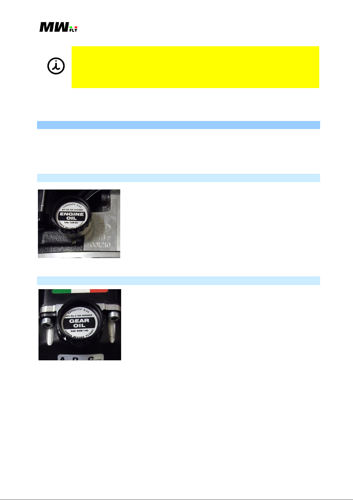
B.3.3.1.P
CAPACITY - 2.8 L
API SG OR HIGHER – this identifies the oil
specification as indicated by the American Petroleum
Institute (API)
ENGINE OIL – engine oil
SAE 15W/50 – oil thermal degree 15W/50 (to select the
correct oil thermal degree for the climate conditions of
the use of the engine refer to the Chapter A.10.3)
CHECK BEFORE FLIGHT
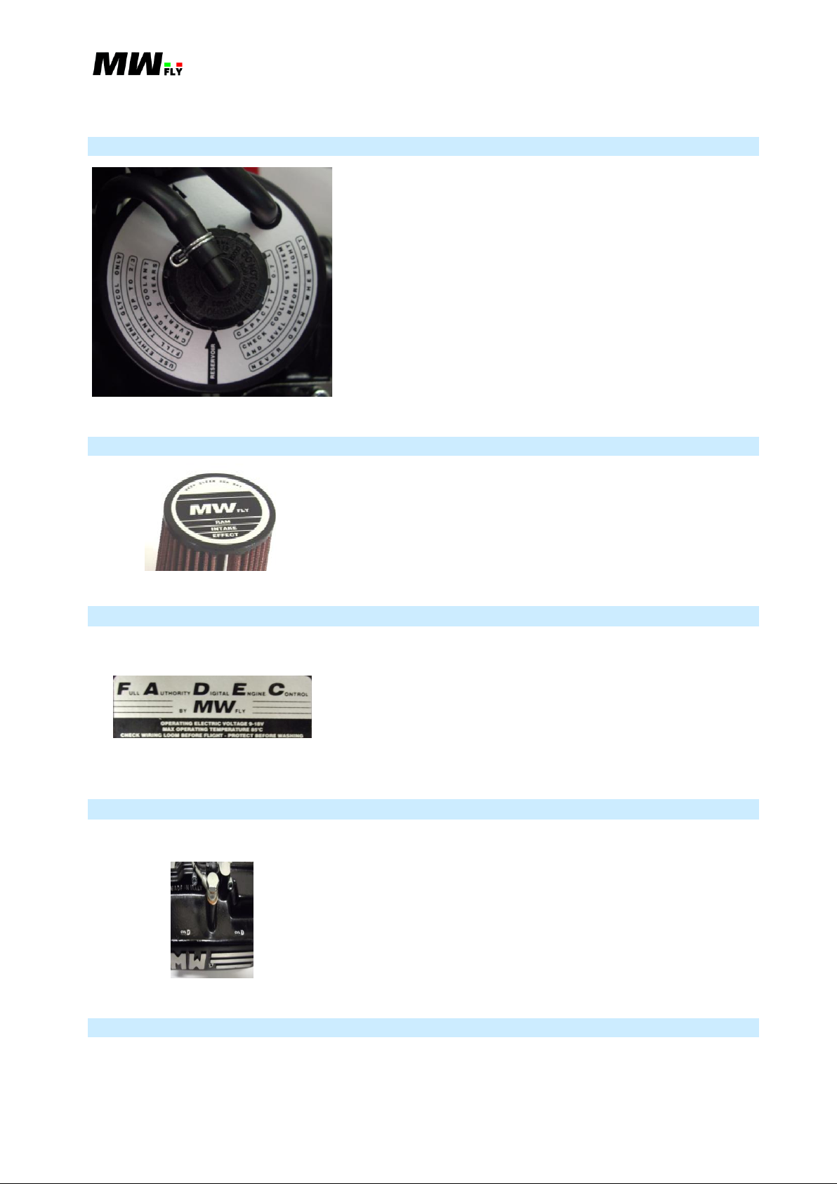
B.3.3.2.P
CAPACITY - 0.3 L
API GL-5 OR HIGHER – this identifies the oil
specification as indicated by the American Petroleum
Institute (API)
GEAR OIL
SAE 85W/140 – oil thermal degree 85W/140
CHECK BEFORE FLIGHT
Where differences exist between this Manual and regulations provided by any authority, the more
stringent regulation should be applied.
B.3.3. Warning labels
There are some warning labels on the engine that indicate the refilling requirements that need to
be done prior to flight as well as other information concerning engine characteristics and
operation. All labels are in English. The following is a list of the labels, their position and
meaning.
B.3.3.1. Engine Oil Filler Cup
B.3.3.2. Reduction Gear Box Oil Filler Cup
Applicable to: B22 and B25 (all versions) Revision 1.3 – 02/24/2015
Manual B – Operations - 15
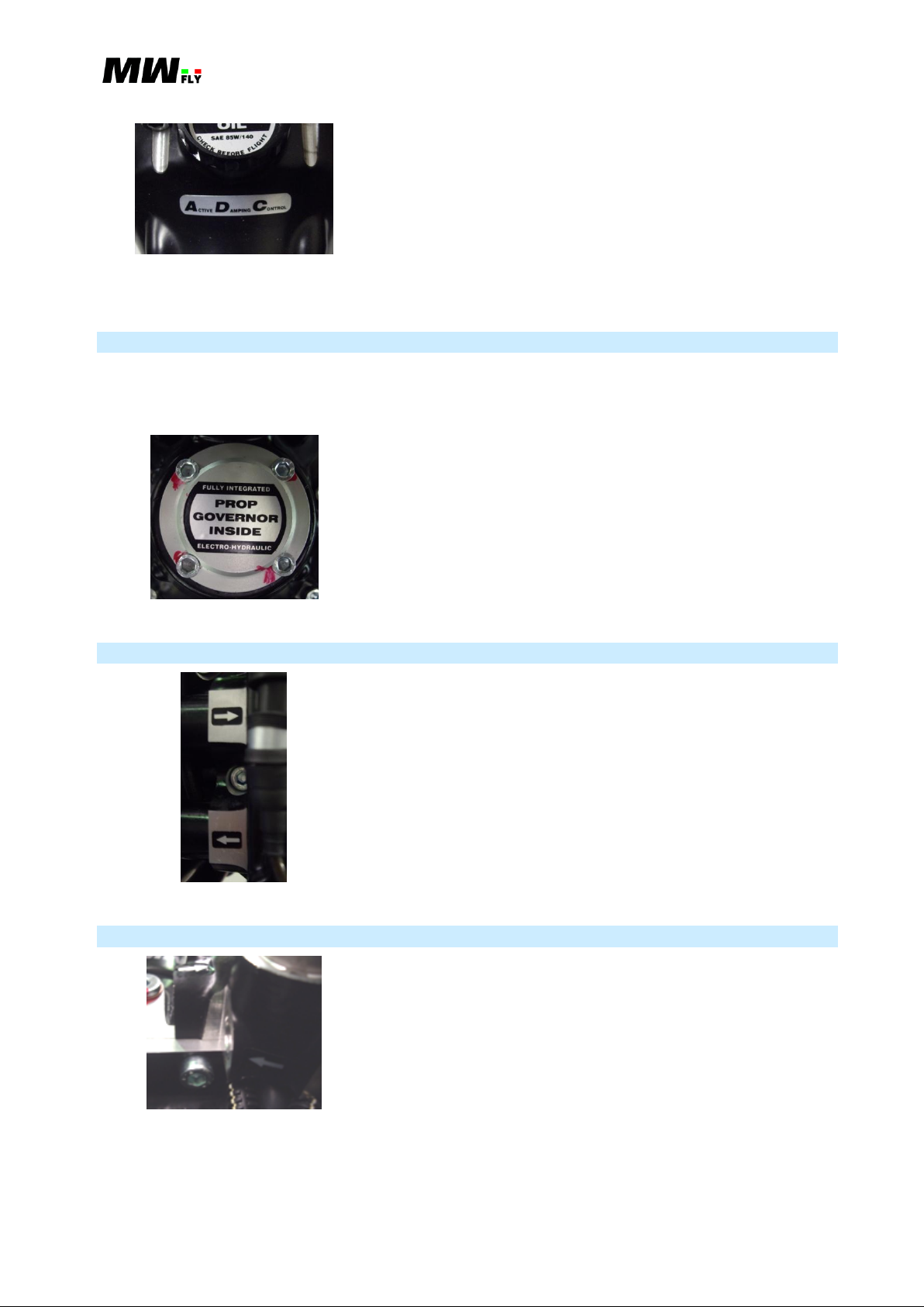
B.3.3.3.P
USE ETHYLENE GLYCOL ONLY –avoid the use of
propylene glycol or just water without ethylene glycol
FILL TANK UP TO 2/3
CHANGE COOLANT EVERY 2 YEARS
RESERVOIR – indicates the expansion tank cup (not
pressurized)
PRESSURIZED – indicates the coolant circuit filler cap
(pressurized)
CAPACITY 0.7 L – Expansion tank capacity
CHECK COOLING SYSTEM AND LEVEL BEFORE
FLIGHT
NEVER OPEN WHEN HOT – this refers to the coolant
circuit pressurized filler cap
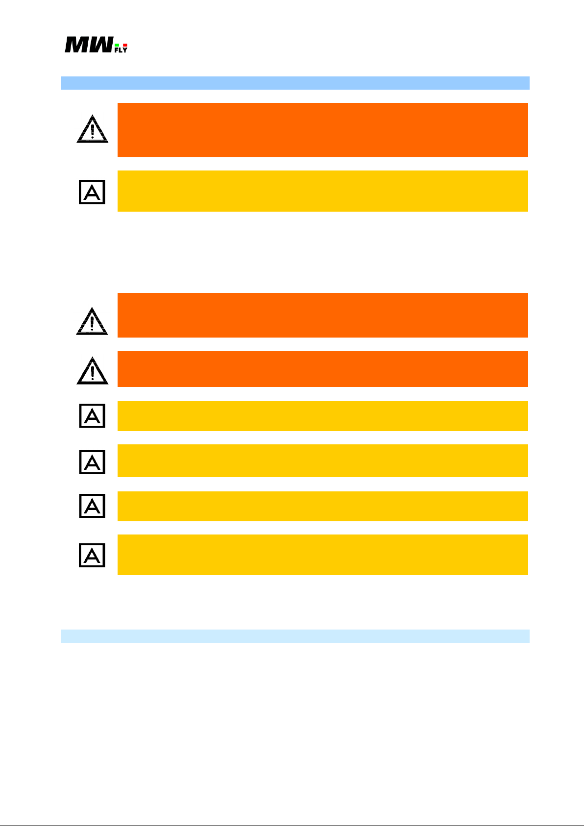
B.3.3.4.P
KEEP CLEAN AND DRY
RAM INTAKE EFFECT – the intake manifold is
designed to take advantage of the “ram effect”
B.3.3.5.P
FULL AUTHORITY DIGITAL ENGINE CONTROL
(F.A.D.E.C.)
OPERATING ELECTRICAL VOLTAGE 9-18V
MAX OPERATING TEMPERATURE 85°C
CHECK WIRING LOOM BEFORE FLIGHT
PROTECT BEFORE WASHING
B.3.3.6.P
CYL1 – Cylinder number 1
CYL2 – Cylinder number 2
CYL3 – Cylinder number 3
CYL4 – Cylinder number 4
This label is not present on the engine model without reduction gear box.
B.3.3.3 Water Expansion Tank
B.3.3.4. Air Filter
B.3.3.5. ECU
This label is placed on the rear side of the ECU‘s bracket.
B.3.3.6. Head Cover
This label, on the engine head cover, indicates the cylinder number as indicated in Chapter B.4.3.
B.3.3.7. Reduction Gear Box
This label is placed on the upper side of the reduction gear box and indicates the Active Damping
Control designed for the AeroPower (B.5.5) family of engines.
Applicable to: B22 and B25 (all versions) Revision 1.3 – 02/24/2015
Manual B – Operations - 16
B.3.3.7.P
ACTIVE DAMPING CONTROL
B.3.3.8.P
PROP GOVERNOR INSIDE
FULLY INTEGRATED ELECTRO-HYDRAULIC
B.3.3.9.P
The arrows are place in correspondence to the in and out
water pump manifold and indicate the direction of the water
flow. The lower manifold is the output line from the engine
to the radiator and the upper manifold is the inlet line from
the radiator to the engine.
B.3.3.10.P
The arrows are placed on the fuel distributor and indicate
the distributor fuel in and out flow. The arrow on side#2
(left side) indicates the inlet line from the fuel pump to the
fuel distributor and the arrow on side#1 (right side)
indicates the outlet return line from the distributor to the
fuel tanks.
This label is not present on the engine version without a reduction gear box.
B.3.3.8. Governor
The engine with reduction gear box can also have an integrated constant speed electro-hydraulic
governor (A.15.1.2.) installed. In this case there is label on the governor oil pump cover on the
front side of the reduction gear box.
B.3.3.9. Water Circuit Arrows
B.3.3.10. Fuel Circuit Arrows
Applicable to: B22 and B25 (all versions) Revision 1.3 – 02/24/2015
Manual B – Operations - 17
Any modification or removal of any part of the engine can cause a dangerous
situation. Substitution of the original parts of the engine with non-original
parts can seriously compromise the technical characteristics of the engine and
its performance.
Any kind of modification, substitution or removal of engine parts not approved by
MW Fly will cause an immediate suspension of the warranty and will release MW
Fly from any liability.
Carefully check that the accessory doesn’t interfere with any part of the
engine that is in motion. Pay particular attention to verify that it doesn’t
interfere with the throttle command or with the propeller.
For no reason modify the engine wiring harness. Do not modify the engine
map of the ECUs.
Avoid installing any accessory that can block the normal coolant flow.
Always check that the total electrical absorption of all the electronic components
installed on the aircraft is not greater than the power supplied by the generator.
It is mandatory to connect each electronic component to the battery supply by using
a fuse (better if a breaker).
The use of non MW Fly original spare parts could compromise the correct
operation of the engine. In this case the guarantee is no longer valid and will
release MW fly from any liability.
B.3.4. Modifications and Accessories
All original MW Fly accessories have been designed and tested to operate with the engine. Since
MW Fly cannot test all of the accessories available on the market so that the operator is
responsible for the choice and installation of the non OEM accessories. Choose an accessory with
respect to the following:
For the installation and the maintenance of the engine, use only the consumables, accessories and
tools indicated at the beginning of each paragraph.
B.3.4.1. Original Accessories
The following is a list of the original accessories available for the A eroP ower engine:
Adapter for bed mounting (cod. S039)
Fuel pump (cod. Q030)
Shock absorber 45Sh (cod. M028), 60Sh (cod. M034), 70Sh (cod. M038), 80Sh (cod. M039)
Standard exhaust system (cod. C075)
Standard radiator kit (cod. C101)
Fuel Delivery Module FD-m (cod. Q050)
Electric Hub Module EH-m (cod. E591)
Applicable to: B22 and B25 (all versions) Revision 1.3 – 02/24/2015

Manual B – Operations - 18
The user is responsible for the risk of not using original accessories and spare
parts. These components can seriously compromise flight safety or change
engine characteristics and performance.
Use only MW Fly original spare parts. These are available to any authorized MW
Fly service center. In case of non-fulfillment the guarantee will not any longer
valid.
Tool ES-m (cod. K472)
Accessories for PVV hydraulic constant speed (cod. C104)
Accessories for governor for constant speed control (cod. C103)
2-Blade Propeller hub for PVV system (cod. C030)
B.3.5. Use of the Technical Documentation
The technical documentation is an essential educational instrument. For complete education it is
necessary to take part in the training courses for the correct installation and use of the engine.
The information given in the engine technical documentation is based on data and experience that
is considered applicable for professionals under normal conditions.
A – Installation Manual: includes all necessary information for the correct installation of the
engine.
B – Operations Manual: includes all the necessary information to correctly operate the engine.
C – Maintenance Manual: includes all the necessary information to correctly execute the
planned maintenance program of the engine.
D – Heavy Maintenance Manual: includes all the information to correctly execute any
unplanned maintenance as the result of an engine failure.
E – Illustrated Parts Catalogue: includes the list of all of the spare parts and accessories.
F – Overhaul Manual: includes all necessary information to carry out a complete overhaul of
the engine because the engine life has reached the TBO, or as a result of a serious failure.
L – Service Letter: includes all the information to upgrade the product or to improve the use
of the engine.
Q – Quick Start Guide: The content is extracted from Manual A
S – Service Bulletin: includes the modifications, control and caution that are required to be
done not later than the date indicated.
X – Alert Service Bulletin: includes all the mandatory modifications, controls and cautions
that must be done before flying.
The rapid technical progress and variations of installation might render present laws and
regulations inapplicable or inadequate.
The illustrations in this Manual are mere sketches and show a typical arrangement. They may not
represent the actual part in all its details but depict parts of the same or similar function. Therefore
deduction of dimensions or other details from illustrations is not permitted.
All necessary documentation is available from the MW Fly Authorized Distributors or their
Service Centers.
Applicable to: B22 and B25 (all versions) Revision 1.3 – 02/24/2015

Manual B – Operations - 19
Name
Model
Version
Power
[CV]
Engine RPM
[rpm]
Prop RPM
[rpm]
B22D
MWB
A
95
3300
3300
B22H
MWB
B
131.5*
4300
---
B22L
MWB
C
114.7
3950
2280
B22R
MWB
D
130.3
4550
2320
B25D
MWC
E
110
3300
3300
B25L
MWC
F
133.1
3950
2280
B25R
MWC
G
154.2
4550
2320
B25H
MWC
H
156*
4300
---
B.4. ENGINE DESCRIPTION
B.4.1. General Characteristics
4 stroke Otto cycle
4 cylinder boxer
Single Over Head Camshaft (SOHC), timing with gears and chain, cam follower and tapper
with valve shim, two valves per cylinder.
Cooling system with a coolant and pump with two different circuits, one for each side of the
engine, expansion tank and thermostat integrated on the engine. All cooling circuit pipes are
stainless steel.
Forced lubrication with internal gear (geretor) pump, semi-dry sump without external pipe.
Mapped ignition f(RPM,MAP), with inductive coil, with dwell time mapped f(VBATT) and
ignition correction f(engine temperature)
Mapped fuel injection f (RPM,MAP), with correction f(engine temperature, air temperature)
Data transmission from the ECUs to EMS system on CAN bus
Fuel system with an electric fuel pump controlled by the ECUs, and an auxiliary electric fuel
pump, the fuel circuit is done with steel pipe, and the fuel pressure regulator is integrated in
the fuel circuit
The reduction gear box uses specific oil that is separate from the engine oil, it has a helical
gear and monolithic propeller shaft, and it is designed for an oil pump for the hydraulic
constant speed governor.
ADC (Automatic Damping Control) to control the torsional vibration up to 2500 rpm
Electric starter motor and start relay pre-installed on the engine
Oil cooled alternator and voltage regulator pre-installed on the engine.
B.4.2. Engine Models
The following table summarizes the main features of the A eroPower family of engines.
Next to the name is shown the model and the respective version, which appears in the
identification code shown on the top of each engine. (see picture B.2.3.1.P).
B.4.2.1.C
* Data refers to the version without reduction gear box
The B22H and B25H models are available with or without a reduction gear box. In the second
case the performance is reduced by 5%.
All of the engine models can be supplied with a pre-installed EMS kit which includes sensors and
cables for any EFIS and EMS instrumentation with a CAN line available to receive the data from
the ECUs. For more detail see paragraph A.16.1.
Applicable to: B22 and B25 (all versions) Revision 1.3 – 02/24/2015

Manual B – Operations - 20
ULL
UTHORITY I GITAL NGINE ONTROL
FLYBY
MAX OPERATING TEMPERATURE 85°C
CHECK WIRING LOOM BEFORE FLIGHT -
OPERATING ELECTRIC VOLTAGE 9-18V
PROTECT BEFORE WASHING
RESERVOIR
PRESSURIZED
N
E
V
E
R
O
P
E
N
W
H
E
N
O
T
H
C
A
P
A
C
I
T
0
.
Y
7
L
U
S
E
E
T
H
Y
L
E
N
E
E
C
H
A
N
G
E
C
O
O
L
A
N
T
V
E
R
Y
2
Y
E
A
R
S
E
C
E
A
H
C
O
C
K
I
L
O
N
S
T
E
L
D
N
O
F
E
B
E
R
T
H
G
I
L
F
G
S
Y
M
L
E
V
G
L
Y
C
L
O
O
N
Y
L
F
A
T
L
L
I
O
T
P
U
K
N
/
3
2
API SG OR HI GHER
C
H
E
C
B
I
F
O
R
E
F
L
G
H
T
K
E
GE A R
SAE 15W/50
T
I
C
A
P
A
C
8
.
2
Y
L
OI L
API SG OR HI GHER
C
H
E
C
B
I
F
O
R
E
F
L
G
H
T
K
E
EN G IN E
SAE 15W/50
T
I
C
A
P
A
C
8
.
2
Y
L
OI L
#1
#2
#3
#4
side #1
Side # 2
The EMS is not integrated in the engine identification code, because that option is available for all
of the engines as an aftermarket kit.
B.4.3. Cylinder Numeration and Position
The cylinders are numbered in the same order that they fire. From a top view of the engine (as
show in picture B.4.3.1.P), cylinder #1 is on the top left, cylinder #2 is on the bottom left, cylinder
#3 is on top right and cylinder #4 is on the bottom right. The same criterion is used to number the
sides of the engine; cylinder #1 and #2 are on side #1 and cylinder #3 and #4 are on side #2.
To know the position of all components of the engine see paragraph A.4.3.
Applicable to: B22 and B25 (all versions) Revision 1.3 – 02/24/2015
B.4.3.1.P

Manual B – Operations - 21
If not specified, the data refers to all engine models.
For safe use of the engine, always respect the operation limits and the
prescribed maintenance time table.
It is not possible to extend the guarantee condition for different uses of the engine.
MW Fly declines any responsibility for damage or bodily injury due to the
improper end use of the engine.
An improper end use of the engine will cause an immediate suspension of the
guarantee and will release MW fly from any liability.
The engine life cannot exceed the TBO limit (see table C.5.2.1.C): when the engine
reach the TBO limit it’s mandatory a complete overhaul check of the engine that
should be done only by an MW Fly authorized service center.
For engine safety it’s important to install and operate in correct way. It important to
use the instrumentation to control that all the engine parameters indicated in the
paragraph A.9.2, are in the operating limit in any working condition.
B.5. TECHNICAL CHARATERISTICS
B.5.1. End Use
B
22
and B25 AeroPo wer engines have been designed to equip ULM, Experimental
and LSA aircraft, two or three axis, with power requirements that conform to the power delivered
by the engine.
AeroPower engines are designed exclusively for recreational purposes in installations where
a sudden stoppage of the engine does not compromise flight safety.
Applicable to: B22 and B25 (all versions) Revision 1.3 – 02/24/2015
Manual B – Operations - 22
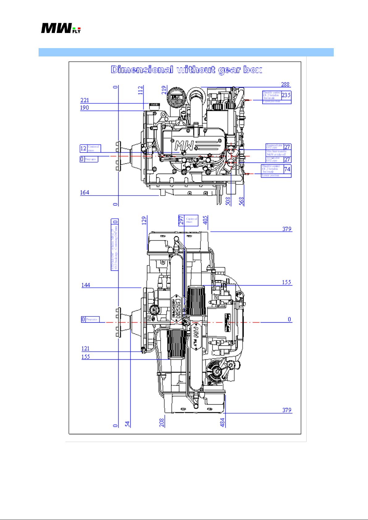
B.5.2. Dimension
Applicable to: B22 and B25 (all versions) Revision 1.3 – 02/24/2015
B.5.2.1.P

Manual B – Operations - 23
Ø13 bushings - Centering Ø47mm
STD hub Ø4" - 6 holes M8x1.25
0
209
144
121
84
0
Prop axis
OI LO IL
L
F
SAE 85W/ 140
ONTROL
T
H
G
I
AMPINGCTIVE
C
E
K
R
O
F
B
E
C
E
H
.
3
GE A RGE A R
API GL-5 OR HIGHER
L
A
P
A
C
I
T
0
Y
C
98
L
Y
C
Y
O
O
L
N
PRESSURIZ ED
560
284
3CYL CY L 4
C
E
K
C
D
O
L
C
L
E
E
V
R
V
E
E
P
O
7
L
T
O
L
I
I
Y
0
N
G
W
N
E
H
O
R
E
F
B
E
S
N
.
F
Y
M
E
L
S
T
O
H
T
I
G
H
T
G
E
K
Y
A
E
RESERVOIR
N
P
H
A
C
C
A
E
N
S
U
N
H
T
T
E
E
L
Y
A
E
N
R
E
H
C
F
I
L
A
V
N
G
E
L
S
/
L
O
A
L
O
R
A
E
Y
C
U
P
T
O
2
N
2
T
3
379
C
A
P
A
L
2
.
8
E
OI LO IL
SAE 15W/50
API SG OR HIGHER
EN G IN EE NG IN E
T
F
G
L
F
E
R
I
O
H
C
K
B
C
E
H
C
I
Y
T
CHECK WIRIN G LOOM BEFORE FLIGHT -PROTECT BEFORE WASHINGPROTECT BEFORE WASHING
MAX OPERATING TEMPERATURE 85°C
OPERATING ELECTR IC VOLTAGE 9-18V
FLY
ONTROLNGINE
BY
IGITALUTHORITYU LL
0
209
Dimensional w ith gear box
68
0
247
0 0
205
Center of
mass
Prop axis
88
107
0
188
mass
Center of
1CYL
371
481
CY L 2
644
584
379
Throttle control
Lower position
3m length
Ø1.2 bowden
Max heat transfer
34.5kW at take off
157
110
To radiator
Ø32 pipe
56
Prop axis
Ø32 pipe
From radiator
0
D
C
P
N
295
EFFECT
INTAKE
RAM
E
K
E
Y
FL Y
R
D
A
L
E
N
A
3m length
Upper position
Throttle control
Ø1.2 bowden
151
204
Applicable to: B22 and B25 (all versions) Revision 1.3 – 02/24/2015
B.5.2.2.P

Manual B – Operations - 24
Max dimension [mm]
direction -
direction +
Total
Max along X axis
10
644 (568*)
654 (578*)
Max along Y axis
379
379
758
Max along Z axis
247 (164)
204 (288)
451
Weight [Kg]
Dry
With lubricants
B22D/B25D
79.5
82.3
B22H*/B25H*
78.7
81.5
B22L/B25L
83.6
86.6
B22R/B25R
83.6
86.6
Adapter for bed mount (4 pieces)
0.37 Kg
Exhaust system
~ 5.1 Kg
Coolant radiator kit
~ 1.7 Kg
Auxiliary fuel pump
0.66 Kg
Governor**
~0.5 Kg
Propeller with hub **
---
Instrument ES-m (without wiring
loom)**
---
EH-m (Electric Hub Module)
~ 0.98 Kg
FD- m (Fuel Delivery Module)
~ 2.75 Kg
The value and the graph of the present chapter indicate the engine performance
with 15°C of air temperature and at sea level (1013 mbar) and with 0% of humidity
(condition ISA-International Standard Atmosphere).
Maximum Dimensions of the Engine
B.5.2.1.C
* model without reduction gear box
The tolerance on these dimensions is ±1 mm.
B.5.3. Weight
Table B.5.3.1.C shows the dry weight of the engine and the weight with lubricants. The weight
includes all the accessories needed to fly (internal generator, voltage regulator, starter relay,
thermostat, water expansion tank, throttle control, fuel injection wiring loom, two ECU’s, rubber
mounting, air filter). Only the radiator coolant and exhaust system are not included in the weight
shown in the table.
B.5.3.1.C
* Model without reduction gear box; with the reduction gear box the weight is 83.6 and 86.6.
B.5.3.1. Optional Accessory Weight
** Data not available
B.5.4. Performance
Applicable to: B22 and B25 (all versions) Revision 1.3 – 02/24/2015
Manual B – Operations - 25
B22 Version
Power [HP (kW)]
B22D
B22H*
B22L
B22R
Take off (max for 5 minutes)
@rpm
95 (69.8)
@3400
131.5 (96.7)
@4300
114.7 (84.3)
@3950
130.3 (95.8)
@4550
max continuous
@rpm
82 (60.3)
@3320÷3400
112.5 (82.7)
@4300
98 (72)
@4010÷4200
110 (80.9)
@4420÷4700
Smaller specific consumption
@MAP[inHg]
64 (47.1)
@24
92.5 (68)
@25.6
84.5 (62.1)
@25.6
96.5 (70.9)
@25.7
B25 Version
Power [HP (kW)]
B25D
B25H*
B25L
B25R
Take off (max for 5 minutes)
@rpm
110 (80.8)
@3400
156 (114.6)
@4300
133.1 (97.9)
@3950
154.2 (113.4)
@4550
max continuous
@rpm
95 (69.8)
@3330÷3400
133.5 (98.1)
@4300
115 (84.5)
@4070÷4200
132 (97)
@4500÷4700
Smaller specific consumption
@MAP[inHg]
74.2 (54.5)
@24
111.5 (82)
@25.7
98.5 (72.4)
@25.7
116 (85.3)
@25..8
During flight the preferred power is set with high RPM and low MAP.
The use of the engine at maximum continuous power for a long period can
seriously damage the engine and can cause a sudden stoppage of the engine.
B.5.4.1.C
* Data refers to the engine model without reduction gear box
B.5.4.2.C
* Data refers to the engine model without reduction gear box
The use of the engine at maximum power is only allowed for 5 minutes continuous. The
maximum continuous power is a function of the MAP and RPM: the limit at high RPM is due to
the thermodynamics; the limit at low RPM is to avoid overload on the reduction gear box.
In the following paragraph there is the performance graph for each engine model:
Graph POWER/RPM and TORQUE/RPM: this is the maximum power and the maximum
torque with the engine at full throttle in function of RPM.
Graph NECESSARY POWER/AVAILABLE POWER: this is the range of use of the engine,
(the area between the two graphs), the graph of the available power, is the power output of the
engine, the necessary power is the power that is required to keep the speed of the propeller
constant (a propeller that makes the engine run at maximum RPM limit and not over). The
graph also indicates, in bold, the maximum continuous power.
Graph POWER/RPM with constant MAP: each graph refers to a different value of MAP as
indicated in inches of mercury (inHg) and indicates the power in function of the RPM. The
bold indicates the maximum continue power in function of the RPM.
Applicable to: B22 and B25 (all versions) Revision 1.3 – 02/24/2015

Manual B – Operations - 26
5% difference from the graph is permitted.
Graph POWER/MAP with constant RPM: each graph indicates the power output in reference
to the different values of RPM in function of MAP. The bold indicates the maximum
continuous power in function of the MAP.
Applicable to: B22 and B25 (all versions) Revision 1.3 – 02/24/2015
Manual B – Operations - 27
B.5.4.1. B22D
20@3400
95@3400
12
14
16
18
20
22
24
26
30
40
50
60
70
80
90
100
2000 2250 2500 2750 3000 3250
[HP]
[Kgm]
[RPM]
B22D Performance @ full throttle
Power
Torque
0
10
20
30
40
50
60
70
80
90
100
2000 2250 2500 2750 3000 3250
[HP]
[RPM]
Range of use B22D
Available power
Necessary power
Max cont. power
B.5.4.3.C
Applicable to: B22 and B25 (all versions) Revision 1.3 – 02/24/2015
B.5.4.4.C
Manual B – Operations - 28
20
30
40
50
60
70
80
90
100
2000 2250 2500 2750 3000 3250 3500
[[HP]
[RPM]
B22D Power @ constant MAP
29.9
28.5
27
25.5
24
22.5
max
cont.
20
30
40
50
60
70
80
90
100
22 23 24 25 26 27 28 29 30
[HP]
[inHg]
B22D Power @ constant RPM
3400
3250
3000
2750
2500
2250
2000
max cont.
B.5.4.5.C
Applicable to: B22 and B25 (all versions) Revision 1.3 – 02/24/2015
B.5.4.6.C

Manual B – Operations - 29
B.5.4.2. B22H
131,5@4300
22@4200
14
16
18
20
22
24
26
28
30
32
50
60
70
80
90
100
110
120
130
140
2250 2500 2750 3000 3250 3500 3750 4000 4250
[HP]
[Kgm]
[RPM]
B22H performace @ full throttle
Power
Torque
Max cont.
112,5@27,8inHg
60
70
80
90
100
110
120
130
140
22 23 24 25 26 27 28 29
[HP]
[inHg]
B22H Power @ 4300 giri
B.5.4.7.C
Applicable to: B22 and B25 (all versions) Revision 1.3 – 02/24/2015
B.5.4.8.C

Manual B – Operations - 30
B.5.4.3. B22L
20,8@3950
114,7@3950
14
16
18
20
22
24
26
28
50
60
70
80
90
100
110
120
2250 2500 2750 3000 3250 3500 3750 4000
[HP]
[Kgm]
[RPM]
B22L Performance @ full throttle
Power
Torque
0
20
40
60
80
100
120
2500 2750 3000 3250 3500 3750 4000
[HP]
[RPM]
B22L Range of use
Available power
Necessary power
Max cont. power
B.5.4.9.C
Applicable to: B22 and B25 (all versions) Revision 1.3 – 02/24/2015
B.5.4.10.C

Manual B – Operations - 31
30
40
50
60
70
80
90
100
110
120
2750 3000 3250 3500 3750 4000 4250
[HP]
[RPM]
B22L Power @ constant MAP
29,9
28,5
27
25,5
24
22,5
max cont.
30
40
50
60
70
80
90
100
110
120
22 23 24 25 26 27 28 29 30
[HP]
[inHg]
B22L Power @ constant RPM
4200
4000
3750
3500
3250
3000
2750
max cont.
B.5.4.11.C
Applicable to: B22 and B25 (all versions) Revision 1.3 – 02/24/2015
B.5.4.12.C

Manual B – Operations - 32
B.5.4.4. B22R
21@4200
130,3@4550
14
16
18
20
22
24
26
28
30
32
50
60
70
80
90
100
110
120
130
140
2250 2500 2750 3000 3250 3500 3750 4000 4250 4500
[HP]
[Kgm]
[RPM]
B22R Performace @ full throttle
Power
Torque
0
20
40
60
80
100
120
140
2500 2750 3000 3250 3500 3750 4000 4250 4500
[HP]
[RPM]
B22R Range of use
Available Power
Necessary Power
Max. cont. Power
B.5.4.13.C
Applicable to: B22 and B25 (all versions) Revision 1.3 – 02/24/2015
B.5.4.14.C

Manual B – Operations - 33
30
40
50
60
70
80
90
100
110
120
130
140
2750 3000 3250 3500 3750 4000 4250 4500 4750
[HP]
[RPM]
B22R Power @ constant MAP
29.9
28.5
27
25.5
24
22.5
max cont.
30
40
50
60
70
80
90
100
110
120
130
140
22 23 24 25 26 27 28 29 30
[HP]
[inHg]
B22R Power @ constant RPM
4700
4500
4250
4000
3750
3500
3250
3000
max cont.
B.5.4.15.C
B.5.4.16.C
Applicable to: B22 and B25 (all versions) Revision 1.3 – 02/24/2015

Manual B – Operations - 34
B.5.4.5 B25D
23,2@3400
110@3400
12
14
16
18
20
22
24
26
28
30
30
40
50
60
70
80
90
100
110
120
2000 2250 2500 2750 3000 3250
[HP]
[Kgm]
[RPM]
B25D Performance @ full throttle
Power
Torque
0
20
40
60
80
100
120
2000 2250 2500 2750 3000 3250
[HP]
[RPM]
B25D Range of use
Available power
Necessary power
Max. cont. power
B.5.4.17.C
Applicable to: B22 and B25 (all versions) Revision 1.3 – 02/24/2015
B.5.4.18.C

Manual B – Operations - 35
20
30
40
50
60
70
80
90
100
110
120
2000 2250 2500 2750 3000 3250 3500
[HP]
[RPM]
B25D Power @ constant MAP
29.9
28.5
27
25.5
24
22.5
max cont.
20
30
40
50
60
70
80
90
100
110
120
22 23 24 25 26 27 28 29 30
[CV]
[inHg]
B25D Power @ constant RPM
3400
3250
3000
2750
2500
2250
2000
max cont.
B.5.4.19.C
Applicable to: B22 and B25 (all versions) Revision 1.3 – 02/24/2015
B.5.4.20.C

Manual B – Operations - 36
B.5.4.6. B25H
156@4300
26,1@4200
16
18
20
22
24
26
28
30
32
34
36
60
70
80
90
100
110
120
130
140
150
160
2250 2500 2750 3000 3250 3500 3750 4000 4250
HP]
[Kgm]
[RPM]
B25H Performance @ full throttle
Power
Torque
Max cont.
133,5@27,8inHg
60
70
80
90
100
110
120
130
140
150
160
22 23 24 25 26 27 28 29
[HP]
[inHg]
B25H at 4300 RPM
B.5.4.21.C
Applicable to: B22 and B25 (all versions) Revision 1.3 – 02/24/2015
B.5.4.22.C

Manual B – Operations - 37
B.5.4.7. B25L
24,1@3950
133,1@3950
16
18
20
22
24
26
28
30
32
60
70
80
90
100
110
120
130
140
2250 2500 2750 3000 3250 3500 3750 4000
[HP]
[Kgm]
[RPM]
B25L Performance @ full throttle
Power
Torque
0
20
40
60
80
100
120
140
2500 2750 3000 3250 3500 3750 4000
[HP]
[RPM]
B25L Range of use
Available power
Necessary power
Max. cont. power
B.5.4.23.C
Applicable to: B22 and B25 (all versions) Revision 1.3 – 02/24/2015
B.5.4.24.C

Manual B – Operations - 38
30
40
50
60
70
80
90
100
110
120
130
140
2750 3000 3250 3500 3750 4000 4250
[HP]
[RPM]
B25LPower @ constant MAP
29.9
28.5
27
25.5
24
22.5
max cont.
30
40
50
60
70
80
90
100
110
120
130
140
22 23 24 25 26 27 28 29 30
[HP]
[inHg]
B25L Power @ constant RPM
4200
4000
3750
3500
3250
3000
2750
max cont.
B.5.4.25.C
Applicable to: B22 and B25 (all versions) Revision 1.3 – 02/24/2015
B.5.4.26.C

Manual B – Operations - 39
B.5.4.8. B25R
24,9@4200
154,2@4550
16
18
20
22
24
26
28
30
32
34
36
60
70
80
90
100
110
120
130
140
150
160
2250 2500 2750 3000 3250 3500 3750 4000 4250 4500
[HP]
[Kgm]
[RPM]
B25R Performance @ full throttle
Power
Torque
0
20
40
60
80
100
120
140
160
2500 2750 3000 3250 3500 3750 4000 4250 4500
[HP]
[RPM]
B25R Range of use
Available power
Necessary power
Max. cont. power
B.5.4.27.C
Applicable to: B22 and B25 (all versions) Revision 1.3 – 02/24/2015
B.5.4.28.C

Manual B – Operations - 40
30
40
50
60
70
80
90
100
110
120
130
140
150
160
2750 3000 3250 3500 3750 4000 4250 4500 4750
[HP]
[RPM]
B25R Power @ constant MAP
29.9
28.5
27
25.5
24
22.5
max cont.
30
40
50
60
70
80
90
100
110
120
130
140
150
160
22 23 24 25 26 27 28 29 30
[HP]
[inHg]
B25R Power @ constant RPM
4700
4500
4250
4000
3750
3500
3250
3000
max cont.
B.5.4.29.C
Applicable to: B22 and B25 (all versions) Revision 1.3 – 02/24/2015
B.5.4.30.C

Manual B – Operations - 41
50%
60%
70%
80%
90%
100%
0 500 1000 1500 2000 2500 3000 3500 4000
[m]
% performance variation based on height
80%
85%
90%
95%
100%
105%
110%
115%
120%
-20 -10 0 10 20 30 40
[°C]
% performance variation based on air temperature
B.5.4.9. Performance Variation
Outside of the ISA conditions, the performance of the engine can vary based on height, air
temperature and humidity.
The variation of engine performance based on height is approximately 1% every 100 meters of
height. The graph B.5.4.18.C shows the variation of engine performance based height.
B.5.4.31.C
The variation of the engine performance not in the standard ISA conditions can be calculated with
the following formula:
Q=Q(ISA)*288/T(K)
Where Q is the power calculated, Q(ISA) is the power in standard ISA condition and T(K) is the
temperature in Kelvin degree : T(K)= T(°C)+273.
The graph B.5.4.19.C shows the power variation based on air temperature.
Applicable to: B22 and B25 (all versions) Revision 1.3 – 02/24/2015
B.5.4.32.C

Manual B – Operations - 42
The fuel injection system automatically changes the quantity of fuel based on the
air temperature and height, so that the engine will run with the correct air//fuel ratio
in any atmospheric condition.
Ratio power
weight [HP/Kg]
Dry weight
Engine with
lubricant
B22D
1.19
1.15
B22H*
1.67
1.61
B22L
1.37
1.32
B22R
1.56
1.50
B25D
1.38
1.34
B25H*
1.98
1.91
B25L
1.59
1.54
B25R
1.84
1.78
All consumption data indicated in the manual refers to the engine running with the
“Power” mode (engine fuel map “Power”). With the engine running in “Economy”
mode the fuel consumption is 10% less than the value indicated.
B22 Version
Consumption[l/h]
@rpm/MAP [inHg]
B22D
B22H*
B22L
B22R
Take off
23.7@3400/29.9
29.8@4300/29.9
29.6@4200/29.9
32.5@4700/29.9
Max continuous
19.6@3320/27.7
25@4300/27.8
23.8@4010/27.7
25.5@4420/27.7
At 75% max cont.
15.5@3020/26
19.2@4300/24.6
17.2@3640/25.7
19.6@4020/25.5
At 65% max cont.
14.2@2880/25.5
---
16@3470/24.8
17.2@3830/24.5
At 55% max cont.
12.8@2720/25
---
13.9@3280/23.7
14.8@3620/23.7
There is no significant variation in engine performance based on the humidity.
B.5.5. Ratio Power/Weight
Table B.5.5.1.C shows the value of the power/weight ratio for all engine models both with and
without lubricant.
B.5.5.1.C
* Data refers to the model without reduction gear box.
B.5.6. Fuel Consumption
The fuel consumption is a function of the power output and the fluid-dynamic conditions.
The following table indicates the consumption in 5 different flight conditions.
B.5.6.1.C
* Data refers to the engine model without reduction gear box
Applicable to: B22 and B25 (all versions) Revision 1.3 – 02/24/2015

Manual B – Operations - 43
B25 Version
Consumption[l/h]
@rpm/MAP [inHg]
B25D
B25H*
B25L
B25R
Take off
27.6@3400/29.9
35.4@4300/29.9
34.5@4200/29.9
38.5@4700/29.9
Max continuous
23@3330/27.7
29.6@4300/27.8
28@4070/27.7
30.3@4500/27.7
At 75% max cont.
17.8@3030/25.7
22.8@4300/24.6
20.9@3700/25.6
23.5@4090/25.5
At 65% max cont.
16.2@2880/25.3
---
18.7@3530/24.6
20.6@3900/24.5
At 55% max cont.
14.7@2730/24.8
---
15.9@3330/23.4
17.4@3690/23.4
Deviations from the curves shown are possible to the extent of 5%, as a result of
dimensional tolerances and assembly.
B.5.6.2.C
* Data refers to the engine model without reduction gear box
The fuel consumption indicated in the table refers to an engine working with a fixed pitch
propeller, so that the engine power output is unequivocally related to the propeller speed. In the
case of a variable pitch propeller, it is possible to calculate the fuel consumption using the
following graph. As a general consideration, with the same power output, the consumption is
lower at higher RPM and lower throttle position.
The following paragraph indicates the fuel consumption of each engine model:
Graph CONSUMPTION PER H/RPM with constant MAP: each curve refers to a value of
MAP (indicated in inches of mercury inHg), and it is the fuel consumption in liters per hour,
in function of the RPM.
Graph CONSUMPTION PER H/MAP constant speed: each curve refers to a regime of
rotation of the motor and returns the hourly consumption expressed in liters, obtained as a
function of pressure in the inlet manifold pressure (MAP).
Graph CONSUMPTION PER H/RPM at constant power: each curve is related to a certain
value of power and represents the consumption per hour, expressed in liters, depending on the
engine regime. This graph is particularly useful, if you use a variable pitch propeller in flight,
to evaluate which is the best consumption with the same horsepower output.
Graph specific consumption / MAP constant speed: each curve refers to a regime of rotation
of the engine and is the hourly consumption, expressed in liters, per horse power output,
expressed in grams of fuel.
Applicable to: B22 and B25 (all versions) Revision 1.3 – 02/24/2015

Manual B – Operations - 44
B.5.6.1. B22D
5
7
9
11
13
15
17
19
21
23
25
2000 2250 2500 2750 3000 3250 3500
[L/h]
[RPM]
B22D Consumption @ constant MAP
29,9
28,5
27
25,5
24
22,5
5
7
9
11
13
15
17
19
21
23
25
22 23 24 25 26 27 28 29 30
[L/h]
[inHg]
B22D consumption @ constant RPM
3400
3250
3000
2750
2500
2250
2000
B.5.6.3.C
B.5.6.4.C
Applicable to: B22 and B25 (all versions) Revision 1.3 – 02/24/2015

Manual B – Operations - 45
9
10
11
12
13
14
15
16
17
18
19
20
21
22
23
24
2000 2250 2500 2750 3000 3250
[L/h]
[RPM]
B22D consumption @ constant power
90
85
80
75
70
65
60
55
50
45
40
35
30
170
180
190
200
210
220
230
240
250
260
22 23 24 25 26 27 28 29 30
[gHP/h]
[inHg]
B22D specific consumption @ constant RPM
3400
3250
3000
2750
2500
2250
2000
B.5.6.5.C
Applicable to: B22 and B25 (all versions) Revision 1.3 – 02/24/2015
B.5.6.6.C

Manual B – Operations - 46
B.5.6.2. B22H
5
10
15
20
25
30
35
22 23 24 25 26 27 28 29
[L/h]
[inHg]
B22H consumption @ 4300 RPM
160
170
180
190
200
22 23 24 25 26 27 28 29
[gHP/h]
[inHg]
B22H specific consumption @ 4300 RPM
B.5.6.7.C
Applicable to: B22 and B25 (all versions) Revision 1.3 – 02/24/2015
B.5.6.8.C

Manual B – Operations - 47
B.5.6.3. B22L
5
10
15
20
25
30
35
2000 2250 2500 2750 3000 3250 3500 3750 4000 4250
[L/h]
[RPM]
B22L consumption @ constant MAP
29,9
28,5
27
25,5
24
22,5
5
10
15
20
25
30
35
22 23 24 25 26 27 28 29 30
[L/h]
[inHg]
B22L consumption @ constant RPM
4200
4000
3750
3500
3250
3000
2750
B.5.6.9.C
Applicable to: B22 and B25 (all versions) Revision 1.3 – 02/24/2015
B.5.6.10.C

Manual B – Operations - 48
12
13
14
15
16
17
18
19
20
21
22
23
24
25
26
27
28
29
30
2750 3000 3250 3500 3750 4000 4250
[L/h]
[RPM]
B22L consumption @ constant power
110
105
100
95
90
85
80
75
70
65
60
55
50
170
180
190
200
210
220
230
22 23 24 25 26 27 28 29 30
[gHP/h]
[inHg]
B22L specific consumption @ constant RPM
4200
4000
3750
3500
3250
3000
2750
B.5.6.11.C
Applicable to: B22 and B25 (all versions) Revision 1.3 – 02/24/2015
B.5.6.12.C

Manual B – Operations - 49
B.5.6.4. B22R
5
10
15
20
25
30
35
2500 2750 3000 3250 3500 3750 4000 4250 4500 4750
[L/h]
[RPM]
B22R Consumption @ constant MAP
29,9
28,5
27
25,5
24
22,5
5
10
15
20
25
30
35
22 23 24 25 26 27 28 29 30
[L/h]
[inHg]
B22R consumption @ constant RPM
4700
4500
4250
4000
3750
3500
3250
3000
B.5.6.13.C
Applicable to: B22 and B25 (all versions) Revision 1.3 – 02/24/2015
B.5.6.14.C

Manual B – Operations - 50
12
13
14
15
16
17
18
19
20
21
22
23
24
25
26
27
28
29
30
31
32
2750 3000 3250 3500 3750 4000 4250 4500 4750
[L/h]
[RPM]
B22R Consumption @ constant power
125
120
115
110
105
100
95
90
85
80
75
70
65
60
55
50
170
180
190
200
210
220
230
22 23 24 25 26 27 28 29 30
[gHP/h]
[inHg]
B22R specific consumption @ constant RPM
4500
4700
4000
4250
3750
3500
3250
3000
2750
B.5.6.15.C
Applicable to: B22 and B25 (all versions) Revision 1.3 – 02/24/2015
B.5.6.16.C

Manual B – Operations - 51
B.5.6.5. B25D
5
10
15
20
25
30
2000 2250 2500 2750 3000 3250 3500
[L/h]
[RPM]
B25D Consumption @ constant MAP
29.9
28.5
27
25.5
24
22.5
5
10
15
20
25
30
22 23 24 25 26 27 28 29 30
[L/h]
[inHg]
B25D Consumption @ constant RMP
3400
3250
3000
2750
2500
2250
2000
B.5.6.17.C
Applicable to: B22 and B25 (all versions) Revision 1.3 – 02/24/2015
B.5.6.18.C

Manual B – Operations - 52
9
10
11
12
13
14
15
16
17
18
19
20
21
22
23
24
25
26
27
2000 2250 2500 2750 3000 3250
[L/h]
[RPM]
B25D Consumption @ constant power
105
100
95
90
85
80
75
70
65
60
55
50
45
170
180
190
200
210
220
230
240
250
260
22 23 24 25 26 27 28 29 30
[gCv/h]
[inHg]
B25D Specific consuption @ constant RPM
3400
3250
3000
2750
2500
2250
2000
B.5.6.19.C
Applicable to: B22 and B25 (all versions) Revision 1.3 – 02/24/2015
B.5.6.20.C

Manual B – Operations - 53
B.5.6.6. B25H
5
10
15
20
25
30
35
40
22 23 24 25 26 27 28 29
[L/h]
[inHg]
B25H Consumption @ 4300 RPM
160
170
180
190
200
22 23 24 25 26 27 28 29
[gCv/h]
[inHg]
B25H Specific consumption @ 4300 RPM
B.5.6.21.C
B.5.6.22.C
Applicable to: B22 and B25 (all versions) Revision 1.3 – 02/24/2015

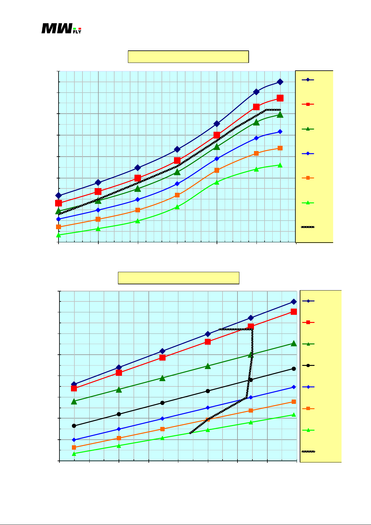
Manual B – Operations - 54
B.5.6.7. B25L
5
10
15
20
25
30
35
40
2000 2250 2500 2750 3000 3250 3500 3750 4000 4250
[L/h]
[RPM]
B25L Consumption @ constant MAP
29.9
28.5
27
25.5
24
22.5
5
10
15
20
25
30
35
40
22 23 24 25 26 27 28 29 30
[L/h]
[inHg]
B25L Consumption @ constant RPM
4200
4000
3750
3500
3250
3000
2750
B.5.6.23.C
Applicable to: B22 and B25 (all versions) Revision 1.3 – 02/24/2015
B.5.6.24.C

Manual B – Operations - 55
12
14
16
18
20
22
24
26
28
30
32
34
2750 3000 3250 3500 3750 4000 4250
[L/h]
[RPM]
B25L Consumption @ constant Power
130
125
120
115
110
105
100
95
90
85
80
75
70
65
60
55
170
180
190
200
210
220
230
22 23 24 25 26 27 28 29 30
[gCv/h]
[inHg]
B25L Specific consumption @ constant RPM
4200
4000
3750
3500
3250
3000
2750
B.5.6.25.C
B.5.6.26.C
Applicable to: B22 and B25 (all versions) Revision 1.3 – 02/24/2015

Manual B – Operations - 56
B.5.6.8. B25R
5
10
15
20
25
30
35
40
2500 2750 3000 3250 3500 3750 4000 4250 4500 4750
[L/h]
[RPM]
B25R Consumption @ constant MAP
29.9
28.5
27
25.5
24
22.5
5
10
15
20
25
30
35
40
22 23 24 25 26 27 28 29 30
[L/h]
[inHg]
B25R Consumption @ constant RPM
4700
4500
4250
4000
3750
3500
3250
3000
B.5.6.27.C
Applicable to: B22 and B25 (all versions) Revision 1.3 – 02/24/2015
B.5.6.28.C

Manual B – Operations - 57
12
14
16
18
20
22
24
26
28
30
32
34
36
38
2750 3000 3250 3500 3750 4000 4250 4500 4750
[L/h]
[RPM]
B25R Consumption @ constant power
150
145
140
135
130
125
120
115
110
105
100
95
90
85
80
75
70
65
60
50
170
180
190
200
210
220
230
22 23 24 25 26 27 28 29 30
[gCv/h]
[inHg]
B25R Specific consumption @ constant RPM
4500
4700
4000
4250
3750
3500
3250
3000
2750
B.5.6.29.C
Applicable to: B22 and B25 (all versions) Revision 1.3 – 02/24/2015
B.5.6.30.C

Manual B – Operations - 58
Model
Gear box ratio
Max engine
RPM[rpm]
Max prpeller speed
[rpm]
B22D/B25D
1÷1
3400
3400
B22H*/B25H*
1÷1
4300
---
B22L/B25L
1÷1,731
4200
2426
B22R/B25R
1÷1,958
4700
2400
B.5.7. Propeller speed
The maximum propeller speed varies depending on the motor model used. Below is a summary:
B.5.7.1.C
* Also available with reduction gear with a ratio of 1 to 1,731 or 1 to 1,958
The models B22D, B25D, B22H and B25H are not provided with a reduction gear box. The
propeller shaft rests on two ball bearings of large dimensions and is keyed directly on the engine
crank shaft.
In the other models with reduction gear box and helical gears, whose ratio is specified in the table,
splash lubrication occurs with specific oil for the gears contained in the gearbox itself. This oil
does not participate in the lubrication of any other mechanical parts. The shafts of the gear box
are made integrally with the gear. Each wheel shaft runs on ball bearings of a significant size.
The gearbox is not equipped with any mechanical damper. Torsional vibrations are reduced by an
electro-hydraulic system placed in the engine block and controlled by the ECU. This system
reduces the degree of irregularity of the engine at low speeds (below 2500 rpm in versions with a
reduction gear box and under 1400 rpm in direct drive versions), making it unnecessary to adopt a
mechanical damper.
B.5.8. Direction of the Rotation of the Propeller
Propeller rotation is viewed by standing in front of propeller (see picture B5.8.1P and B5.8.2P). It
is counter clockwise for the version without gear box and clockwise for the version with gear box.
B.5.8.1.P
Applicable to: B22 and B25 (all versions) Revision 1.3 – 02/24/2015

Manual B – Operations - 59
Version w ith gear box
Never manually rotate the propeller in the opposite direction. This operation can
damage the automatic timing chain tensioner and also disengage the system on the
engine starter.
For engines with a reduction gear box, the counterclockwise rotation of the
propeller produces a drift to the right of the aircraft. Counter this on the ground
with the left pedal and properly balance in flight with aerodynamic surfaces of
compensation. For versions without a gear box it is the opposite.
B.5.8.2.P
Applicable to: B22 and B25 (all versions) Revision 1.3 – 02/24/2015

Manual B – Operations - 60
Optional
Supplied (standard equipm ent)
Thermostate
full
Over
Head
Cylinder
valve
effec t
Double
Pum p
Cylinder
Side 1
Head
Side 2
Radiator
T> 75°C
Vaso espansione
Tem perature
sensor
Tem perature
sensor
T< 75°C
Hot circuit
Cold circuit
Water tank
B.6. DESCRIPTION OF THE SYSTEMS
B.6.1. Cooling system
For a detailed description of the system, see the paragraph A.9.1.
Applicable to: B22 and B25 (all versions) Revision 1.3 – 02/24/2015
B.6.1.1.C

Manual B – Operations - 61
Dec om pr.
Cra nk case
Scondary shaft
Rods
lubrication
Spray
Oil filter
Non-ret urn valve
By-pass valve
Pressuruzed
lubrication
Oil sum p
oil st rainer
Pump
tim ing c hain 1
Pressure
sensor
Pistons
valve
ADC
Head 1
bearings
Camshaft
Tappet
Start
sensor
gears
Splash
lubrication
gears
Tim ing
Tem erature
Tim ing chain 2
Bearings
Tappet
bearings
Camshaft
Head 2
Generator
Dec om pr.
The temperature of the coolant is measured by two temperature sensors (optional), installed in
each head.
B.6.2. Lubricant system
For a detailed description of the system, see the paragraph A.10.1.
An oil temperature sensor is mounted on the right rear of the oil sump. The data from the sensor
is sent to the injection control unit: do not remove or intercept the signal from this sensor for any
reason. If you need to add an oil temperature sensor read paragraph A.16.3. The engine lubricant
pressure is measured by a sensor placed on the upper left side of the crankcase under the injection
control unit.
Applicable to: B22 and B25 (all versions) Revision 1.3 – 02/24/2015
B.6.2.1.C

Manual B – Operations - 62
net
valve
filter
Airc raft fuel circ uit
Optional to be insta lled on the aircraft
installed on the engine
cylinder 3/4
Auxliary
in line
fuel pum p
n et
Filt er
Non-ret urn
Fuel
Injector
fuel pum p
Main
in line
Filt er
n et
water
Ga scoletor
Non-ret urn
valve
filter
Fuel
Pressure
sensor
Filt er net
fuel dist ributor
Pressure
regulator
Fuel t ank
Filt er
net
Filt er
cylinder 1/2
Injector
Fuel
valve
Fuel tank
In case of the use of two tanks it is essential to install a dual flow valve, which
can act on both the delivery branch and on the return to the tank. A valve
with these characteristics is available as an accessory with the cod. C107.
In case a safety valve is installed on the return to the fuel tank it is important
to install a non-return valve, as close as possible to the tank: this valve is to
prevent the fuel contained in the tanks from flowing to the engine or into the
cabin in the event of rollover or serious damage to 'fuel system.
B.6.3. Fuel system
B.6.3.1.C
Applicable to: B22 and B25 (all versions) Revision 1.3 – 02/24/2015

Manual B – Operations - 63
It is important to avoid the risk of vapor lock in the return line to the fuel tanks.
Coc k pit
Instrum ent Panel
F.D.U.
Elect ric-Hub
Battery A Battery B
Engine
Connector
Instrum ent
Push Button
sw itch
EngineCabin
E-Safe
Starter
Start
GND
Engine
GND
StartAAux
pum p laneBlane
Master
The measurement of fuel pressure is performed by a sensor positioned on the left side of the
engine on fuel distributor.
B.6.4. Electric system
B.6.4.1.C
The engine is equipped with two injection ECUs and electronic ignition mapped with barometric
and altimeter compensation and totally independent electrical circuits.
The ignition system is electronic inductive discharge with resistive shielding against radio
interference. The firing order is 1-2-3-4, with the numbering shown in Figure B.4.2.1.P
Applicable to: B22 and B25 (all versions) Revision 1.3 – 02/24/2015

Manual B – Operations - 64
If the engine is operated with generator disconnected from the controller, you need
to check and possibly replace the generator.
Read and understand the instruction manual of the instruments before performing
flight or ground tests.
Do not start the engine before connecting the instruments to the electrical wiring
since the system would detect the event as an anomaly.
The injection system is equipped with two high impedance injectors (one per bank). The mixture
is adjusted by varying the injection time.
The recharging circuit uses a 300 Watt generator with anti-phased windings, oil cooled, and a 26
A voltage regulator.
Carrying out the aircraft wiring loom according to the schema defined in the installation manual
allows the engine to also be operated with the battery disconnected or broken. This is possible
only if the engine speed is greater than 1500 rpm. Under 1500 rpm the current requested by the
one fuel pump and the injection and ignition system is greater than the current produced by the
generator.
B.6.4.1. ES-m Instrumentation
ES-m and EMS-m instrumentation is an integral part of every engine, ensuring the correct and
safe use of the engine. Through this instrumentation the operator can monitor the operating status
of the ECUs, fuel pumps, batteries and generator. The HSA-M can also record the values of all
the operating parameters of the engine (rpm, temperatures, pressures, hours of operation and
more), and all of which is available on a CAN line with the standard CAN Aerospace protocol.
This makes is very easy to connect additional instruments to the system. For a list of the functions
and the correct method of use, refer to the respective user manuals.
Applicable to: B22 and B25 (all versions) Revision 1.3 – 02/24/2015

Manual B – Operations - 65
B22 Version
RPM
B22D
B22H
B22L
B22R
Take Off (max 5 minuts)
3400
4300
3950÷4200
4550÷4700
Max Continuous Power (MCP)
3320
4010
4420
95% MCP
3260
3940
4350
90% MCP
3210
3870
4270
85% MCP
3150
3800
4190
80% MCP
3080
3720
4100
75% MCP
3020
3640
4020
70% MCP
2950
3560
3930
65% MCP
2880
3470
3830
60% MCP
2800
3380
3730
55% MCP
2720
3280
3620
50% MCP
2640
3180
3510
idle
950÷1050
1350÷1700*
950÷1050
950÷1050
Best range**
2700÷3000
---
3400÷3750
3400÷4200
B25 Version
RPM
B25D
B25H
B25L
B25R
Take Off (max 5 minuts)
3400
4300
3950÷4200
4550÷4700
Max Continuous Power (MCP)
3330
4070
4500
95% MCP
3270
4000
4420
90% MCP
3220
3930
4350
85% MCP
3150
3860
4260
80% MCP
3090
3780
4180
75% MCP
3030
3700
4090
70% MCP
2960
3610
4000
65% MCP
2880
3530
3900
60% MCP
2810
3430
3800
55% MCP
2730
3330
3690
50% MCP
2640
3230
3570
idle
950÷1050
1350÷1700*
950÷1050
950÷1050
Best range**
2700÷3000
---
3400÷3750
3400÷4200
B.7. OPERATING INSTRUCTION
B.7.1. Operating limits
B.7.1.1. RPM
The two ECUs use a pick up (one for each ECUs) to read the engine RPM. The RPM are the one
read from the ECUs.
B.7.1.1.C
B.7.1.2.C
* operation in neutral
** only with constant speed propeller
Applicable to: B22 and B25 (all versions) Revision 1.3 – 02/24/2015

Manual B – Operations - 66
Exceeding the maximum allowable engine speed is a condition of potential risk to
the integrity of the engine and must be prevented by using propellers with
appropriate characteristics for power output.
Fuel Pressure [bar]
B22D/B25D
B22H/B25H
B22L/B25L
B22R/B25R
Max
3.6.
3.6
3.6
3.6
Min
2.9
2.9
2.9
2.9
Max variation with auxiliary pump on
0.15
0.15
0.15
0.15
In the case of pressures above or below the values shown, the engine operates
in an irregular manner. Do not fly until the problem is identified and resolved.
It is mandatory to monitor the fuel pressure during the flight, in order to detect any
abnormalities that may affect safety.
It is strongly suggested to install an auxiliary fuel pump, to be used in case of
failure of the main pump in flight or in conditions of safety critical flight (takeoff
and landing).
Engine oil pressure [bar]
B22D/B25D
B22H/B25H
B22L/B25L
B22R/B25R
Max
2.2
2.2
2.2
2.2
Nominal @ max rpm
1.4÷1.8
1.7÷2.2
1.6÷2.0
1.7÷2.2
Min below 2500 (1400*) rpm
0.05
0.05
0.05
0.05
Max below 2500 (1400*) rpm
0.6
0.6
0.6
0.6
Min over 2500(1400*) rpm
1.2
1.2
1.2
1.2
Nominal @ 3000 rpm
1.5÷1.7
1.5÷1.7
1.5÷1.7
1.5÷1.7
The power percentages expressed in the table refers to installations with a fixed pitch propeller
and it is supposed that the propeller, in flight, reaches the maximum permissible engine speed.
B.7.1.2. Fuel Pressure
The fuel pressure is detected by a sensor (optional) mounted on the shunt fuel. The fuel pressure
increases as the opening of the throttle control, and then the value of MAP.
B.7.1.3.C
The minimum value is reached in release conditions of release (low throttle and high engine
speed).
B.7.1.3. Engine oil pressure
The engine oil pressure is read by a sensor placed on the main rail of the oil circuit, before the oil
filter and after the valve ADC. The oil pressure is strongly affected by the temperature and
viscosity of the oil.
B.7.1.4.C
* Engine version without reduction gear box
The oil pressure is electronically regulated below 2500 rpm (1400 rpm in versions without
gearbox). In case of an anomaly of the control system it is possible to read the oil pressure value
different from the one shown in idle conditions. Sometimes it may happen that there is an
increase in vibration to a minimum or below 2500 rpm during the first minutes of engine operation
Applicable to: B22 and B25 (all versions) Revision 1.3 – 02/24/2015

Manual B – Operations - 67
It is mandatory to monitor the engine oil pressure during the flight to detect any
abnormalities that may affect safety.
Such an eventuality is not dangerous for flight conditions, but it must be corrected
to avoid inducing abnormal stress to the mechanical and structural components of
the aircraft when the engine is idling.
B22 Version
Engine Oil Temperature [°C]
B22D
B22H
B22L
B22R
Max
130
130
130
130
Min before flight
50
50
50
50
Nominal
85÷100
100÷120
85÷105
95÷110
Typical
90
110
95
102
B25 Version
Engine Oil Temperature [°C]
B25D
B25H
B25L
B25R
Max
130
130
130
130
Min before flight
50
60
50
50
Nominal
85÷100
100÷120
90÷100
95÷115
Typical
92
115
100
106
It is mandatory to monitor the temperature of the lubricant during flight in order to
detect any abnormalities that may affect safety.
with cold starts, particularly in cold climates (ambient temperature less than 5 ° C), even when
with automatic procedure ended. In this case, by varying the position of the throttle, look for the
engine speed that produces less vibration. This is usually about 1800 rpm.
The fault of the oil pressure control of the ADC system produces an increase of vibration in idle
condition.
B.7.1.4. Engine Oil Temperature
The engine oil temperature is read by a sensor mounted in the rear of the oil sump.
B.7.1.5.C
B.7.1.6.C
The engine oil temperature is an important indicator of the thermal state of the motor, more so
than the temperature of the coolant and must be considered for the purpose of engine warm up.
B.7.1.5. Reduction Gear Box Oil Temperature
The gearbox oil temperature is not detected by any specific sensor as it is not critical or binding
for engine reliability. It can be read with adhesive thermometers as described in the installation
manual.
Applicable to: B22 and B25 (all versions) Revision 1.3 – 02/24/2015

Manual B – Operations - 68
Version without governor
Reduction Gear Box Temperature [°C]
B22L/B25L
B22R/B25R
Max
100
100
Min in flight
/
/
Nominal
45÷70
45÷80
Typical
55
60
Version with governor
Reduction Gear Box Temperature [°C]
B22L/B25L
B22R/B25R
Max
125
125
Min in flight
/
/
Nominal
60÷95
65÷105
Typical
90
95
Coolant Temperature [°C]
B22D/B25D
B22H/B25H
B22L/B25L
B22R/B25R
Max
102
102
102
102
Min in flight
72
72
72
72
Nominal
75÷90
85÷98
75÷90
80÷95
Typical
85
92
87
90
It is mandatory to monitor the temperature of the coolant during the flight in order
to detect any abnormalities that may affect safety.
Air Intake Temperature [°C]
All versions
Max
-70
Min
-20
Normal
25
B.7.1.7.C
B.7.1.8.C
The oil temperature reducer represents an index of the efficiency of the gears of the transmission.
In case of overheating is necessary to overhaul the gearbox.
B.7.1.6. Coolant Temperature
The temperature of the cooling liquid is detected by a sensor, one for each bank.
B.7.1.9.C
B.7.1.7. Air Intake Temperature
The air intake temperature is detected in the intake manifold of the cylinder bank # 1 with the
sensor prepared for the injection system. This temperature can be read using an EFIS system with
a CAN interface.
B.7.1.10.C
Applicable to: B22 and B25 (all versions) Revision 1.3 – 02/24/2015

Manual B – Operations - 69
A supply temperature above the reported value indicates a mechanical or
electronic problem. Do not fly until the problem is identified and resolved.
At temperatures below 15°C with particular environmental conditions, frost may
form and impact negatively on the butterfly valve.
The minimum temperature required for ignition must be understood for a cold
engine.
Acceleration [g]
All versions
Longitudinal axis X
± 10
Trasversal axis Y
± 10
Vertical axis Z
+10/-0.5 (max 5 second)
Angle [deg]
All versions
Minimum Oil Level
Maximum Oil Level
Pitch axis
+55/-10
+55/-18
Roll axis
+36/-47
+49/-53
Yaw axis
± 90
±90
With temperatures below 0° C it can be difficult to start the engine if the battery is not fully
charged. If necessary, for cold starting, it is possible to connect a fully charged second battery in
parallel to the one installed on the aircraft.
B.7.1.8. Load Factor
The operating limits of the engine to contingency are due to the need to allow adequate lubricant
to the mechanical action. The fuel injector system is instead substantially insensitive to the
conditions of contingency.
B.7.1.11.C
B.7.1.9. Inclination Angle
Similar as to what is described for the load factor, the limits on the angles of inclination of the
engine with respect to the horizontal position are to guarantee adequate lubrication to the
mechanical action.
B.7.1.12.C
The angles are referred to the condition of minimum and maximum oil levels. On the pitch axis it
consider a positive angle when the flange propeller pull up; on the roll axis it’s consider a positive
angle when the side # 1 to rotate downward.
These angles should be interpreted as angle of skidding relative to the direction of flight: in case
the angle is accompanied by a centrifugal force implicit in maneuvers coordinates, the angles of
inclination may also be more.
Applicable to: B22 and B25 (all versions) Revision 1.3 – 02/24/2015

Manual B – Operations - 70
Electrical Voltage [volt]
All versions
Maximum
14.8
Minimum
9
Normal
12.5÷13.5
The voltage read on a voltmeter is the average between the charging voltage and the
battery voltage. For this reason, with low battery voltage values, the values that are
read are also lower than the normal voltage reported. This condition does not
indicate a failure in charging.
Before performing any maintenance on the aircraft or engine, electronically isolate
the ECU’s from the plant.
The recommended coolant is the SYNAVIO M AF concentrate, which, unlike other
anti-freezes, can be diluted with water even with a high lime content (tap water).
Do not use propylene glycol coolants: the use of these coolants will render void any
conditions or warranties on the engine or on the components of the engine.
The recommended lubricant is SYNAVIO ME 40 Engine Lubricant which is
specifically formulated for heavy-duty on aircraft engines. Synavio provides a free
service of spectrographic analysis of the oil removed (C.6.7.6.).
B.7.1.10 Electrical Voltage
The injection system is able to function properly compensating for any variations in the voltage of
the recharging system within the limits indicated.
B.7.1.13.C
B.7.2. Operative Fluid
B.7.2.1. Cooling Fluid
Use only ethylene glycol based coolants: these liquids must be mixed with water. The protection
from freezing is guaranteed up to -40 ° C when diluted 50%: for different dilutions, refer to the
graph A.9.5.1.C.
B.7.2.2. Engine Oil
Use only synthetic lubricants or those mixed for use in gasoline engines. The multi-grade oil SAE
10W/40 covers a very wide range of ambient temperatures and is therefore to be considered the
first choice for temperate climates such as Europe. Only use lubricants with specific API SG or
higher.
Applicable to: B22 and B25 (all versions) Revision 1.3 – 02/24/2015

Manual B – Operations - 71
If the oil consumption is higher than specified it is necessary to revise the engine.
The use of oil different from the one recommended, even if it is of equal degree and
specific heat, is not recommended as the effectiveness has not been verified in
testing.
After the first 10 hours of operation it is necessary to replace the oil and oil filter.
Not replacing the oil and filter can cause engine performance degradation and
possible damage to the engine.
The recommended lubricant is the SYNAVIO MG 90 Gear Lubricant which is
specifically formulated for heavy-duty gears with high stress. Synavio provides a
free service of spectrographic analysis of the oil removed (C.6.12.5.).
A lubricant consumption higher than that specified is probably due to the
overheating of the transmission gears or leakages from the seals during operation.
In such a case it is necessary to overhaul the gearbox.
The use of oil different from the one recommended, even if it is of equal degree and
specific heat, is not recommended as the effectiveness has not been verified in
testing.
After the first 10 hours of operation it is necessary to change the gearbox oil. Not
doing this can cause damage to the gear reduction or the propeller pitch adjustment
system, if installed.
The choice of the optimal viscosity of the oil to be used should be determined on the basis of the
average atmospheric temperature of the area of use (A.10.3.1.C). If the engine is used in hot
climates it is recommended to increase the frequency of oil changes.
The maximum permissible oil consumption is 0.5 liters every 10 hours of operation regime.
If the engine has not been used for a prolonged period of time it is advisable to change the oil
before use.
B.7.2.3. Reduction Gear Box Oil
Use specific lubricants for use with hypoid gears of thermal grade 80W-90.
The maximum gearbox oil consumption is 0.05 liters every 10 hours.
B.7.2.4. Fuel
The following fuel type can be used:
Unleaded gasoline RON 91 or higher
Leaded gasoline 91 octane or higher
Applicable to: B22 and B25 (all versions) Revision 1.3 – 02/24/2015

Manual B – Operations - 72
The use of AVGAS gasoline has not been verified during testing. Do not use
this type of fuel for any reason as it could severely damage the injectors and
the engine and cause the engine to shutdown.
Replace the fuel filter according to the maintenance schedule. Failure to do so
may cause performance degradation or possible engine failure.
The use of fuel with lower anti-knock characteristics than prescribed may cause
damage to the mechanical components of the engine. In case of accidental use of
these fuels, it is mandatory a check at an authorized service centre.
The formulation of gasoline varies between summer and winter. It is important to
make sure to use fuel prepared for the climatic condition in which the engine
operates.
Risk of burns: always perform pre-flight checks on a cold engine.
Always make sure, before proceeding to the controls, the ECUs switches are in
the off position.
Make sure the master switch is in the off position.
In case of anomalies identified during pre-flight checks do not use the engine
before they are removed.
There is a possibility that there may be water residue or small intrusions present in the fuel. It is
advisable to filter the fuel before placing in the tanks in order to preserve the fuel circuit from
impurities that may damage the components.
Avoid storing fuel for months with the risk of using winter fuel in summer time. Summer fuel has
less evaporation capacity because the more volatile components are removed and this decreases
the risk of vapor lock in the fuel system.
B.7.3. General Criteria to Operate the Engine
To preserve the integrity and efficiency of your engine you need to follow the instructions
contained in the operating and maintenance manuals.
B.7.3.1. Check Before Start
a. General check
Remove the cowling of the engine and check that there is no slack in the tightening, especially
in the radiator, hoses, fuel and cooling system hoses. Check the state of wear of all the
connections made of plastic material and the shock absorbers for the suspension of the engine.
Check there are no cracks or looseness in the engine mounts.
Applicable to: B22 and B25 (all versions) Revision 1.3 – 02/24/2015

Manual B – Operations - 73
Any excess liquid refrigerant is ejected from the system through the tube
arranged on the cap of the expansion tank, once the engine has reached
operating temperature.
Unscrew the cap of the pressurized circuit only when the engine is turned
off and cold otherwise this could result in personal injury and severe
burns.
Check the tightness of the propeller and the absence of any play between the propeller blades
and hub.
b. Leaks Inspection
Check for the leakage of fuel, coolant or lubricant. In particular, before moving the aircraft, it
is good to check the floor below the engine or tanks for the presence of stains or smudges due
to defects in onboard systems. Also consider the fact that, due to the presence of the
propeller, a possible loss of liquid in flight can cause stains or halos far away from the point
where the leak occurs.
c. Cooling Fluid Level Check
Check the coolant level in the expansion tank. The verification shall be carried out by
unscrewing the cap of the expansion tank and checking the level of the refrigerant visually or
with a dipstick. The expansion tank must be filled to at least two thirds of the height (about
0.45 liters). The total capacity of the expansion tank is 0.7 liters.
If necessary, top up coolant with the same quality as the one in the engine.
Make sure you have tightened the seal cap (you should feel some resistance when tightening). In
case the level of the liquid contained in the expansion tank is zero or very low, it is also necessary
to unscrew the cap of the pressurized circuit.
B.7.3.1.P
If the liquid level inside the duct for topping up the pressurized circuit is full, it is sufficient to
unscrew the cap and top up the level in the expansion tank. If the level in the duct for topping
Applicable to: B22 and B25 (all versions) Revision 1.3 – 02/24/2015

Manual B – Operations - 74
If the engine requires frequent topping up of the water circuit is likely that
there is a leak from the head gasket: running the engine in this condition can
cause a detonation phenomena, resulting in serious mechanical damage.
Avoid placing more oil in the engine than the maximum allowed, as it may
cause reflux into the intake system and result in erratic operation and spark
plug fouling.
For tightening and removing the filler cap use the tool code. X283.
For tightening and removing the filler cap you can use the tool code. X283.
In case of considerable gaps, roughness or variation in the propeller rotation
smoothness, contact an authorized service center for the appropriate
inspections.
Avoid turning the propeller in the opposite direction as it may damage the
automatic chain tension distribution system or the starter system.
up the pressurized circuit is low, it is necessary bleed the cooling system as described in
section A.9.6., but not before isolating the cause that led to the low level.
d. Engine Oil Level Check
Check the oil level in the engine and top up if necessary. The oil level should be between the
two notches on the dipstick: the quantity between the two marks is about 0.8 liters.
e. Reduction Gear Box Check
Check the state of wear of the gears and lubricant: this verification shall be performed by
unscrewing the cap on the top of the gearbox and visually assessing the state of the contact
surfaces on the driven gear (helical gear), which must be free of cracks, pitting or yellowing
and have a uniform glossy appearance.
Apply a light load on the end of a propeller blade by hand, first in one direction, then in the
opposite. Do not turn the engine shaft. This makes it possible to evaluate the clearance
between the gears of the gearbox. When the engine is cold the movement of the blade should
be about 1.5 millimeter and should not exceed 3 millimeters.
Rotate the propeller by hand in the direction of normal engine operation by completing at
least one turn: it should be smooth and no suspicious noises should be heard. If so it is
mandatory to check the gear box before flight. The compression of the cylinders with the
engine stopped is very low due to the presence of the decompressor.
f. Fuel System Check
From the cockpit switch on the auxiliary pump for about 5 seconds and then check with the
instrumentation that the fuel system line is pressurized. This means that the fuel pressure is
3.5 bar. After turning off the auxiliary pump and ensuring that the master switch is in the off
Applicable to: B22 and B25 (all versions) Revision 1.3 – 02/24/2015

Manual B – Operations - 75
In the case of leaks or even in doubt, avoid starting the engine and contact
a service center.
A damaged exhaust system causes a reduction in engine performance and
may cause poisoning, burns or fire.
Do not leave the aircraft unattended with the engine running.
Before starting the engine, make sure that nobody is in the proximity of the
aircraft or in the area considered dangerous.
Thanks to the injection system, to perform the start, both with the engine hot, or
with engine cold, it is not necessary to manually adjust the mixture, as the
enrichment is operated in automatic mode.
position follow the fuel line from tank up to the engine and check for leaks or even small
leakages of fuel. Carefully check the area of the shunt fuel, which has to be clean and free of
sludge or smudges of greenish color.
If the FD-m group is installed it is necessary to remove the cover and check for leaks from the
fuel lines and components; also check the clamps holding the pumps.
g. Throttle Command Check
Completely push the throttle command in the cab and return to the idle position: pay attention
to any jamming or roughness in the command.
h. Exhaust System Check
Carefully observe the exhaust manifolds and the muffler and verify the absence of cracks, loss
of lubricant or fuel, or vented exhaust gases, especially in the area of coupling to the engine.
Also check the condition of the springs and retaining screws.
i. Electric System Check
Inspect all electrical connectors and especially the state of the cables from the connectors,
check the tightness of the ground connections and the positive power and check the spark plug
wires and the clamping on the spark plug. Check that all the fixing points of the wiring to the
engine are properly tightened. Check the efficiency of all the fuses and if the fuse and relays
in the engine compartment are properly connected. If the EH-m group is installed check the
efficiency of the damping elements assembly mounting to firewall.
In case of the use of a dual battery system, before starting the engine, check the state of
efficiency of both batteries, bringing the first master switch in position A and then in position
B: in both cases the voltage read must be greater than 11.7 volts, otherwise it is necessary to
recharge the battery before starting the engine.
B.7.3.2. Start Operation
The start-up sequence is as follows.
a. Set the throttle to the idle position.
Applicable to: B22 and B25 (all versions) Revision 1.3 – 02/24/2015

Manual B – Operations - 76
Do not start the engine with throttle in fully open position: this not only makes
starting more difficult, but also may cause damage to the starter system.
Automatic control of the fuel pump is done for safety reasons. If there is a
breakage of the fuel system by accident or any other reason, since the motor
has stopped, the pump will not run so there is no circulation of fuel. The pump
is not of a transparent type so that if it stops it does not allow the passage of
fuel.
The injection system adjusts the idle speed automatically, the idle is set around
1700 ÷ 2300 rpm when the engine is cold (depending on the version and the
propeller mounted), and the idle speed goes down to 950 ÷ 1050 rpm when the
engine is hot.
Do not turn off the engine immediately after starting as this can cause erratic
operation of the ADC system, with the risk of damaging the engine. If you
need to turn off the engine without completing the heating process, it is
mandatory to wait at least 1 minute before trying to start the engine again.
Set the master switch to the on position.
b. Power on the main fuel pump for about 3 seconds, so as to pressurize the fuel system, the
pump will restart automatically when the engine starts and will automatically turn off when
the engine stops.
c. Bring both injection switches to the on position.
d. Checking fuel pressure: if the fuel pressure is greater than 3.1 bar you can operate the engine
starter if the pressure is less than this value it is necessary to activate the auxiliary fuel pump
to pressurize the fuel system; if the auxiliary fuel pump is not installed, you must set the ECU
switch in the off position, wait about 5 seconds, and then set it again in the on position, so as
to switch on the fuel pump again.
e. Push the starter button. The start button should not be pressed for more than 10 seconds
continuously. If after this period the engine has not started, before a second attempt it is
necessary to wait at least 1 minute. This is to safeguard the electric starter from overheating. If
after the third attempt the engine does not start, desist from any further attempts, and perform
the checks in paragraph B.9.1. It is important to operate the starter only if the engine is
completely stopped.
f. After about 30 seconds after the engine start check the oil pressure. It must be within the
allowable limits.
B.7.3.3. Engine Warm Up
The engine warm up procedure is performed in a completely automatic way by the FADEC
system as described below:
a. When starting, with the oil temperature below 50° C, the engine will automatically run at
approximately 1300 rpm and after a few seconds then goes to between 1700 and 2300 rpm.
Applicable to: B22 and B25 (all versions) Revision 1.3 – 02/24/2015

Manual B – Operations - 77
On the ground avoid running the engine above 3200 RPM for more than one
minute because cooling may be inadequate and may cause faults in the engine
components.
Never exceed 3000 RPM with the water temperature below 72° C and the oil
temperature below 50° C. Doing so will cause severe mechanical damage,
recorded in the ES-m memory, and will cancel the warranty on the engine and its
components.
The ES-m instrument facilitates the management of the heating phase and
indicates the condition of “warm up”.
Upon reaching 50° C, the FADEC system will impose a new engine idling speed of between
950 and 1050 RPM.
b. If the oil temperature is above 50° C then the engine will immediately run at a speed of
between 950 and 1050 RPM after starting.
c. The warm up procedure is considered to be finished when the coolant temperature of both
cylinder sides is above 72° C: in case this condition is not verified, it is necessary to keep the
engine at about 2000 RPM to accelerate heating.
B.7.3.4. Before Take Off
When the warm-up period is finished, before take-off, it is necessary to perform some checks and
some operational tests of the engine, as described below:
a. Verify that the fuel pressure in idle condition is greater than 2.9 bar.
b. Verify that the oil pressure in idle condition in greater than 0.1 bar.
c. Run the engine at 2700 rpm and perform the following checks:
d. Rendundancy Check
Alternately turn off each of the two injection systems. After a short period of time, necessary
for re-timing the control units, there must not be any significant variation in either of the RPM
or the regularity of the engine operation.
e. Charging System Check
Turn off the master switch. The engine must remain continue to run without any hesitation.
At the same time the voltage value will increase. The magnitude of the increase depends on
the state of charge of the battery: the increase in voltage is usually between 0.5 and 1.5 volts.
In the case of systems with dual battery you need to check the efficiency of both batteries,
bringing the master switch to position A, B, Both and finally in the off position. The engine
must operate regularly with variations in voltage between 0.5 and 1.5 volts.
f. Auxiliary Fuel Pump Check
Switch on the auxiliary pump. There will be an increase in fuel pressure of about 0.1 bar and
there must be no significant difference in speed.
g. Throttle Response Check
Applicable to: B22 and B25 (all versions) Revision 1.3 – 02/24/2015

Manual B – Operations - 78
If even one of these checks fails, or if there are doubts, it is mandatory not
to fly, and perform all the necessary ground checks.
Never take off with the engine cold, as it can cause serious damage to the
engine and may cause a dangerous situation by stopping the engine in flight.
In cruise condition, by using the ES-m instrumentation, it is possible to activate
the injection map in Economy mode, which provides a fuel saving of about
10%.
Bring the throttle into full open position. The engine should reach the expected RPM.
Bring the throttle back into idle position. The engine should neither turn off nor manifest
irregularities.
Also check that the throttle runs regularly without jamming.
B.7.3.5. Take Off
a. Make sure you have activated the auxiliary fuel pump (if present), and have switched on both
ECUs.
b. Bring the throttle to full open position and execute the take off.
c. Keep the throttle in full open position for the time necessary to gain altitude as quickly as
possible but not for more than five minutes.
d. Bring the throttle to cruise position.
e. Switch off the auxiliary fuel pump while monitoring the pressure in the system. If the
pressure drops after the pump is turned off then switch the auxiliary pump on again and land
as soon as possible to remove the anomaly.
During the climb constantly keep monitoring the values of the motor parameters (waterT, oilT,
oilP and fuelP) checking that they are within the limits specified in section B.7.1.
To avoid overloading the transmission system, do not act on the throttle suddenly to either
increase or decrease the engine rpm.
B.7.3.6. Cruise
a. Set the throttle in order to get the desired cruise attitude, in compliance with the operating
limits listed in Section B.7.1.
b. If using a constant speed propeller, avoid flying at high loads and low rpm because this causes
stress on the gears of the transmission and enhances degradation. It also does not produce any
positive effect on fuel consumption. It is better to set the propeller pitch that makes the
engine run with a MAP value between 24inHg and 27.5inHg and within the range of
maximum continuous power expressed in charts B.5.4.3, B.5.4.9 and B.5.4.13.
c. Monitor engine parameters during flight to detect any malfunctions before they produce
mechanical damage. In particular, avoid flying with the coolant and oil temperatures lower
than the lower limit value. If it this happens reduce the radiant cooling surfaces.
B.7.3.7. Landing
a. Switch on the auxiliary fuel pump if installed.
Applicable to: B22 and B25 (all versions) Revision 1.3 – 02/24/2015

Manual B – Operations - 79
Thanks to the adoption of the liquid cooling system the risk of the sudden drop
of oil and water temperature is avoided during prolonged descent with the
engine idling.
This procedure prevents jerking the propeller while stopping the engine. The ADC
system is handled by the main ECU only. Acting in a different way can cause
problems to the starter.
b. Gradually reduce the rotation speed by adjusting the throttle.
c. When using a constant speed propeller, put the propeller in the minimum pitch, while
reducing the speed by adjusting the throttle.
d. Always gradually control the throttle, without subjecting the engine to rapid regime changes.
B.7.3.8. Engine Switch off
a. After landing, keep the engine running at low speed for at least 1 minute, in order to
standardize the temperatures of all components and avoid thermal shock.
b. Switch off all utilities in the meantime, including the auxiliary fuel pump if present.
c. Stop the engine using the auxiliary ECU first and then the main ECU.
d. After stopping the engine, switch off the main switch (master).
B.7.3.9. Use of the Engine in Winter Season
If using the engine during winter or in a cold climate area you must follow the instructions below:
a. Coolant
Increase the proportion of water-antifreeze mixture in accordance with the paragraph B.7.2.1
and the manufacturer's instructions.
b. Lubricant
Make sure the engine and gearbox lubricant thermal grade used is in compliance to what is
specified in B.7.2.2 and B.7.2.3.
c. Cold Start
Throttle closed.
Make sure that the battery is fully charged to run the engine at least 150-180 RPM. Otherwise
recharge before attempting to start. In case the installed battery is not enough to ensure an
adequate start regime, use a second battery connected in parallel to the first.
Use the electric starter for short periods (10 seconds maximum). During starting attempts
power off and on the main ECU switch: this produces a further enrichment in the carburetion.
d. If the Engine Doesn’t Start
o Open the throttle slightly.
o Replace the spark plug.
o Reduce the spark plug air gap to 0.5 mm (regardless of the type of candle used), to
facilitate the ignition of the spark.
o Use an engine oil that is less viscous.
o Run the engine for 20 seconds without spark plug.
Applicable to: B22 and B25 (all versions) Revision 1.3 – 02/24/2015

Manual B – Operations - 80
It is necessary to use fuel specific to the season in which the engine is used. The
formulation of the fuel varies with the presence of some components or additives,
particularly alcohol, which contains water and may cause condensation under certain
conditions.
If the engine does not start it is likely that there is condensation or ice in the intake
system, due to high relative humidity. In this case it is appropriate to blow or replace
the spark plugs. In addition to this, there is also the possibility of the presence of
water condensation in the fuel. To avoid problems due to the presence of water in
the fuel it is necessary to provide the fuel circuit with a gascolator to be placed at the
lowest point in the circuit itself before the fuel pumps. This will collect, by gravity,
the water which may be present in the tanks.
Be aware that under certain conditions the presence of small drops of water on the
electrodes of the spark plugs can cause irreversible damage.
An advantage of the fuel injection system is that there is no venturi which is present
with a carburetor. The venturi facilitates the formation of ice inside of the intake by
subjecting the air to an expansion.
In extreme cases, even in a fuel injection system, icing can occur in the intake duct
due to the cooling of the condensate on the surface of the throttle valve. This
phenomenon is very rare and occurs only when the engine is cold and there are low
throttle angles (i.e. when the presence of the throttle valve in the inlet manifold
constitutes a barrier for more than 2/3 of the total cross-section).
o Warm up the engine with hot air jets direct to the oil sump and engine heads.
Applicable to: B22 and B25 (all versions) Revision 1.3 – 02/24/2015

Manual B – Operations - 81
If during use, the engine surpasses the limits prescribed in paragraph B.7.1, it
is mandatory to contact an authorized service center before using the engine
again.
Exceeding the operating limits is recorded in the ES-m instrument and will cause
the termination of the product warranty.
The operation of the auxiliary pump and the selection of the auxiliary rpm
sensor serves to exclude prior two possible causes of the shutdown without
wasting time in their detection.
B.7.4. Behavior in Case of Emergency
Each time the operating limits are exceeded it must be noted in the engine booklet, detailing the
value reached and the length of time spent outside the limit. This is required for engine
maintenance or in case the engine is sold.
For additional controls refer to the service manual.
B.7.4.1. Accidental Engine Stop – Start During Flight
a. Exclude all unnecessary electrical loads for the flight.
b. Check and reset the fuse which protects the injection system.
c. According to the failure code highlighted by the ES-m instrument, turn off the unit affected
by the problem. If the ES-m instrument is not installed and the malfunction indicator light
unit is on, exclude the main ECU otherwise exclude the auxiliary ECU.
d. Switch on the auxiliary fuel pump.
e. Put the throttle lever to the idle position.
f. Push the starter switch. If the engine fails to start, repeat the operation by selecting the second
ECU.
g. Land as soon as possible to identify and remove the cause of the failure.
B.7.4.2. Over Rev
The engine is equipped with an electronic system that implements a decrease of controlled power
above the maximum speed allowed. So in case of a propeller setting that is not adequate for the
engine power output, the full performance of the engine is not exploited, but without producing
any particular damage to the engine.
In the event of a dive at full throttle, the engine can be dragged from the propeller caused by the
loss of altitude. In such cases may occur an over rev. If the over rev is limited to 300 rpm over
the operating limits, it is not necessary to make any verification: Write down the event, however,
on the engine booklet. If the over rev is greater than 300 rpm operating limit, see Section C.7.3.8
or contact an authorized service center before taking further flights.
B.7.4.3. Exceeding the Maximum Coolant Temperature
a. Reduce the power to the minimum necessary for the flight as soon as possible and according
to the flight conditions.
Applicable to: B22 and B25 (all versions) Revision 1.3 – 02/24/2015

Manual B – Operations - 82
The engine can run for short periods even with extremely low oil pressure: in
such a case, however, the power drops by about 30%, because the
decompressor cannot be maintained in the closed position by oil pressure. It is
necessary to take this limit into account while operating in emergency
maneuvers.
Do not fly until the cause of the loss of pressure has been determined and
corrected.
b. In the case of installations with constant speed propeller, privilege high speeds with low MAP
value.
c. Land as soon as possible.
B.7.4.4. Exceeding the Maximum Oil Temperature
a. Reduce the power to the minimum necessary for the flight as soon as possible and according
to the flight conditions.
b. In the case of installations with constant speed propeller, privilege high speeds with low MAP
value.
c. Land as soon as possible.
B.7.4.5. Oil Pressure Below the Limit in Flight
a. Reduce the power to the minimum necessary for the flight as soon as possible and according
to the flight conditions.
b. In the case of installations with constant speed propeller, privilege high speeds with low MAP
value.
c. Land as soon as possible.
B.7.4.6. Oil Pressure Below the Limit on the Ground
a. Stop the engine.
b. Check the amount of lubricant in the oil sump and, if necessary, top up.
c. Check for leaks in the lubrication system by checking the area close to the oil filter and on the
top of the engine where the leaked lubricant can easily collect.
B.7.4.7. Fuel Pressure Below the Limit in Flight
a. Open any reserve fuel tanks and activate the auxiliary pump as soon as possible.
o If the fuel pressure increase
b. Bring the aircraft to the closest airfield and land.
o If the fuel pressure do not increase
c. Switch off the auxiliary fuel pump reduce the power to the minimum necessary for the
flight as soon as possible and according to flight condition.
d. Prepare for the possibility that the engine stops due to lack of fuel, identifying areas for
an emergency landing.
Applicable to: B22 and B25 (all versions) Revision 1.3 – 02/24/2015

Manual B – Operations - 83
Gasoline and its vapors are extremely flammable. Do not operate indoors,
near sources of heat or open flame. Avoid using electrical or electronic
equipment in proximity fuel spills.
A fully charged 16Ah battery will keep the motor running for at least 50 minutes
after the generator failure.
If this condition arises, reducing engine speed may cause the engine to stop.
After a generator failure, the entire charging system must be inspected and possibly
replaced.
B.7.4.8. Fuel Pressure Below the Limit on the Ground
Stop the engine and wait at a safe distance while the engine cools down and then run some checks
as summarized below:
o Fill the fuel tanks.
o Look for any fuel leaks below the aircraft or in the upper part of the engine where any leaked
fuel can easily collect.
o If a fuel leak is detected turn off the fuel valve and empty the fuel tanks.
o Do not start the engine until the leak has been corrected.
o Try to operate the auxiliary pump: if the pressure is restored, it means that the main pump is
faulty, do not make any flights until the main pump is replaced.
o Replace the fuel filter.
o Do any further testing pursuant to the instructions in the maintenance manual.
B.7.4.9. Battery Voltage Over the Limit
a. Check the position of the main switch (master) to ensure it is in the “on” position.
b. If the voltage does not reduce the engine speed decreases, according to the flight conditions to
prevent damage to electronic components.
c. Land as soon as possible.
B.7.4.10. Battery Voltage Below the Limit
Check for generator alarm or the status of generator alarm light.
o In case the generator alarm is on
a. There is probably a failure of the voltage regulator: turn off all non essential loads for
the flight.
b. Turn off the control unit and the auxiliary fuel pump in order to decrease power
consumption as much as possible.
c. Set the speed and the engine to about 3500 RPM and, in the case of a variable pitch
propeller increase the speed in order to cover the maximum distance.
d. Land as soon as possible while reducing the speed only just before landing so as to
avoid the engine stopping.
Applicable to: B22 and B25 (all versions) Revision 1.3 – 02/24/2015

Manual B – Operations - 84
Having flown without a battery connected to the system it is necessary to replace
the voltage regulator even if it appears to working.
A fully charged 16Ah battery will keep the motor running for at least 50 minutes
after the generator failure.
If this condition arises, reducing engine speed may cause the engine to stop.
After a generator failure, the entire charging system must be inspected and possibly
replaced.
o In case the generator alarm is off
a. There is probably a battery failure: turn off all non essential loads for the flight.
b. Disconnect the battery from the electrical circuit by switching off the master switch.
c. In proximity of landing site, exclude the main control unit (circuit A): this way the
engine automatically remains above 1500 rpm.
d. Land as soon as possible while paying attention to engine speed.
B.7.4.11. ECU Alarm
o On the ES-m instrument, the ECU lights indicate the type of error (fatal or non-fatal) and the
ECU on which it occurred. In case of a serious error you need to exclude the ECU and land
as soon as possible. In case of a non-fatal error you can continue the flight with both ECUs
running but perhaps with some functional limitation which does not affect flight safety.
o If there is no ES-m instrument, when the ECU alarm light is on it is necessary to switch off
the main ECU, reduce the engine RPM and land as soon as possible.
B.7.4.12. Generator Alarm
a. Check the status of the 30A fuse mounted to protect the charging system, and if possible
restore it.
b. Verify the presence of overload in the electrical system and possibly disconnect utilities
unnecessary or faulty.
c. Turn off the control unit and the auxiliary fuel pump (circuit B) on order to decrease power
consumption as much as possible.
d. Set the speed of the engine to about 3500 RPM and in the case of a variable pitch propeller
increase the speed in order to cover the maximum distance.
e. Land as soon as possible while reducing the speed only just before landing so as to avoid the
engine stopping.
B.7.4.13. Abnormal Vibration
o If the vibrations are very high and may cause structural damage to the aircraft, immediately
stop the engine and prepare for an emergency landing.
o If the vibrations are such that the structural integrity of the aircraft is not compromised:
o Check the ES-m instrument for the presence of errors on the ECUs or the fuel pumps
and act accordingly by turning off any component failure. If the ES-m instrument is not
Applicable to: B22 and B25 (all versions) Revision 1.3 – 02/24/2015

Manual B – Operations - 85
installed exclude the main ECU, if the fault persists, turn on the main ECU and exclude
the auxiliary ECU.
o Gradually reduce the engine RPM to look for a setting in which the vibrations are
lower.
o if it does doesn’t work increase the RPM looking for a new setting in which the
vibrations are lower
o Land as soon as possible.
B.7.4.14. Irregular Operation
o Verify on the ES-m instrument the operational status of the ECUs and fuel pumps and
eventually exclude the component in failure. If the ES-m instrument is not installed, select the
auxiliary ECU or the auxiliary RPM sensor, depending on the engine version.
o Make sure the fuel valve is not accidentally closed.
o If installed, turn on the auxiliary fuel pump.
o Vary the engine RPM to try to improve regularity of operation.
o Land as soon as possible.
Applicable to: B22 and B25 (all versions) Revision 1.3 – 02/24/2015

Manual B – Operations - 86
Only qualified and trained technicians on this particular type of engine are authorized
to perform maintenance work and repairs.
B.8. ENGINE CONTROL
All checks must be carried out according to the methods described in the latest revision of the
maintenance manual.
Keep in mind the directives contained in the Service Bulletins according to their priorities
compared to those described in the manuals.
B.8.1. List of Tool Kit for the Pre-flight Checks or Emergency
It is necessary to have a small set of tools that can be used for pre-flight checks and to bring it in
flight, to perform small jobs in the event of malfunction during the trip.
Scissors
Needle Nose pliers
Phillip screwdriver
5 mm Allen key
6 mm Allen key
8 mm Allen key
8 mm wrench
10 mm wrench
13 mm wrench
17 mm wrench
19 mm wrench
Oil filler lever cod. X283
B.8.2. Shelter from Service for Extended Period of Time
The cylinder liners are made of cast iron so it is necessary to protect them from moisture and
acidic compounds that may be formed during operation of the engine. In addition, valves, valve
guides and valve seats are subject to deterioration during inactivity if not properly protected.
a. Warm up the engine to operating temperatures, then turn it off and change the engine oil and
filter.
b. Remove the air filters and put into the intake collectors about 30 cm3 of anti-corrosion oil
while the engine running at about 1500 rpm. Turn off the engine.
c. When the engine is cold, close the intake manifolds and exhaust pipe with the appropriate
plugs delivered with the engine, or similar, to prevent the entry of foreign matter and
moisture.
d. Spray a corrosion protection on all external engine parts that are made of steel.
B.8.3. Return to Service After Long Inactivity
a. Remove the spark plugs cap.
b. Change the engine oil and gearbox oil if it is scheduled in the maintenance program.
c. Slowly recharge the battery before attempting to start the engine.
d. Check all the connections of the cooling circuit and the fuel tubes. There must be no leaks or
cracks of any kind or damage made by rodents.
e. Check the level of coolant, engine oil and gearbox oil and top up if necessary.
Applicable to: B22 and B25 (all versions) Revision 1.3 – 02/24/2015

Manual B – Operations - 87
f. Purge, through the gascolator, the fuel system in order to remove the possible presence of
water condensation.
g. Turn the engine acting on the propeller in the direction of normal operation and doing at
least 10 turns of the propeller.
h. Replace the spark plugs and the relative cap after checking the integrity (C.6.11.2).
i. Start the pump and check that the auxiliary fuel system reaches operating pressure (3.5 bar).
j. Perform a test engine on the ground, according to the procedure described in paragraph
C.6.5.9.
k. Replace fuel filter according to the procedure described in paragraph C.6.8.4.
B.8.4. Engine Protection When Used in Cold Climates
a. Make sure to use the most correct thermal grade for the engine and gearbox oil.
b. Change the mixing of the antifreeze liquid with water to ensure the right protection against
icing. Check table B.7.2.1.C and the instructions of the manufacturer's recommendation.
c. Use fuel specifically formulated to work in cold climates.
d. Always keep the battery in optimum efficiency.
e. Warm up the engine properly before taking off.
f. Before turning off the engine after use, wait a few minutes for uniform temperatures.
Applicable to: B22 and B25 (all versions) Revision 1.3 – 02/24/2015

Manual B – Operations - 88
The engine must not be used until any problem has been identified and
resolved.
B.9. MALFUNCTION RESOLUTION
Only qualified and trained technicians on this particular type of engine are authorized to perform
maintenance work and repairs.
If the following collection of solutions will not solve the problem you should contact an
authorized service center.
B.9.1. Operation Malfunctions and Their Resolution
The malfunction and remedies are listed in order of frequency.
The engine is hard to start at low temperatures
o Check, and if necessary, correct the battery charge level: at least 11.8 volts.
o Open the throttle slightly.
o Reduce the air gap of the spark plugs to 0.5 mm (regardless of the type of candle used).
o Replace the spark plugs.
The engine doesn’t start
o Make sure that the main switch is in the on position.
o Make sure that the power switch of the ECU is in the on position.
o Check, and if necessary, correct the battery charge level: at least 11.8 volts.
o Make sure that the fuel pressure is at least 3.3 bar, otherwise switch on the auxiliary fuel
pump or, in the case that is not installed, power off and on the ECU switch.
o Select the auxiliary rpm sensor (only not dual version).
o Check that there is fuel in the tanks.
o Replace the fuel filter.
o Replace the spark plugs.
Coolant temperature too low
o The radiator dimensions are too big. Reduce the radiating surface with adhesive tape or cowl
flaps.
o In case of a faulty thermostat it will be hard to even reach the operating temperature. Replace
if necessary.
Oil temperature too low
o Reduce the amount of oil in the sump.
o Increasing the operating temperature of the engine, the radiator, reducing radiator surface and
the air intake vents on the cowling.
Oil pressure low
o Check and if necessary correct engine oil level.
o Replace oil filter.
o Identify possible lubricant leaks under pressure from the head gasket or oil filter.
o Use a lubricant with higher thermal grade.
Take off maximum RPM too low
o Reduce the pitch or diameter of the propeller.
o Possible failure of one of four spark plugs: in this case we note also a marked increase of the
vibrations; change the spark plugs.
o Check the level of engine oil into the sump and top up if necessary.
Applicable to: B22 and B25 (all versions) Revision 1.3 – 02/24/2015

Manual B – Operations - 89
If the engine is hard to start and has a very irregular cold low idle it is likely there is
a problem with the injection system. In this circumstance avoid flying and contact
an authorized service center for encoding and resolution of the anomaly.
o Check the fuel pressure at full throttle: if it does not reach at least 3.5 bar is necessary to
revise the fuel distributor and fuel pumps.
o Check the efficiency of the ADC system and decompression valve.
The coolant in the expansion tank is frequently below the level
o Check the pressurized cap is correctly closed.
o Locate possible leaks from the cooling circuit, corresponding circuit junction.
o Locate possible leaks from the elements of the radiator, due to excessive stress induced by
vibration. If necessary, replace the radiator.
o Check the efficiency of the pressurization valve in the cap: if necessary, replace the cap.
Coolant temperature too high
o Purge the cooling system circuit to remove any air in the cooling circuit.
o Coolant level in the expansion tank too low. Restore level.
o Check the presence of leaks in the cooling circuit which can cause loss of fluid of the system.
o Glycol-water mixture is incorrect, with excess glycol. Correct the percentage in relation to
environment.
Oil temperature too high
o Check the amount of oil into the sump and top up if necessary.
o Possible engine damage: make a thorough inspection of the engine.
Presence of oil emulsion under the oil filler cap or the engine vent system
o Engine operating temperature too low: reduce the surface area of the radiator.
o Head gasket failure: it is necessary to intervene by reviewing the engine.
Excessive vibration
o Propeller tightening incorrect: restore it.
o Propeller is unbalanced due to the presence of deposits or damage.
o Spark plugs dirty or damaged: replace them.
o Try both ECUs: in case the vibration is only with one of the two ECUs, replace the damaged
unit.
o Cylinder banks are not synchronized correctly: contact an authorized service center.
o ADC system is not working correctly: contact an authorized service center.
B.9.2. Anomalies to the Injection and Ignition Systems
The injection system has internal diagnosis capable of detecting errors on the inputs and on the
controls. The system is also equipped with a “Limp Home” strategy which assigns a default value
to the inputs in which the error was detected (with the exception of the entrance pickup) allowing
the engine to continue running. If the strategy is activated, the next cold engine start will be
considerably difficult and the operation erratic.
Very often the anomalies to the injection and ignition systems are caused by problems with the
wiring or the connectors. It is important to devote full attention to these components during
maintenance to avoid pulling or putting unnecessary stress on the wiring or connectors. It is also
important to both periodically and prior to flight to check the positioning of each wiring branch
and fixing it with other elements if there is a danger of unwanted shaking caused by propeller
wash or vibration.
Applicable to: B22 and B25 (all versions) Revision 1.3 – 02/24/2015

Manual B – Operations - 90
Type of Failure
Error
Classification
Limp Home
Management
Default
Value
Input engine RPM
Serious
No
-
Input throttle angle
Non-serious
Yes
100 %
Input oil temperature
Non-serious
Yes
80 °C
Input air temperature
Non-serious
Yes
30 °C
Input water temperature
Non-serious
Yes
80 °C
Input oil pressure
Non-serious
Yes
80 °C
Input fuel pressure
Non-serious
Yes
0 bar
Input barametric pressure
Non-serious
Yes
0 bar
Coil control
Serious
No - Injector control
Serious
No
-
Microprocessor consistancy
Serious
No
-
In case of a serious error it is necessary to exclude the circuit that presents the
anomaly and land as soon as possible.
If the error is non-serious the flight may continue but it will be necessary to
subject the engine to an inspection at an authorized service center.
If the ES-m instrument is installed each error is sent to the CAN line and classified by the
instrument itself as a serious error or as a non-fatal error. The tool is also able to report any error
to circuit A or circuit B. The following table show the classification of errors, whether or not it can
be handled by the “Limp Home” strategy and the default value that is assigned to them.
B.9.2.1.C
B.9.3. Signal Engine Malfunction
Any malfunction should be identified and resolved before proceeding fly.
In order to improve and fix any defects it is important that the user communicate to MW Fly any
anomalies and their resolution or any other consideration that can improve the safety in the use of
the engine and clarity of the information contained in these manuals.
Communications shall be made by filling out the form below. The form can be downloaded from
www.mwfly.it and sent to the closest authorized MW Fly service center or directly by e-mail to
info@mwfly.it.
Applicable to: B22 and B25 (all versions) Revision 1.3 – 02/24/2015

Manual B – Operations - 91
Malfunction format
Date
Serial N°
Last name
Fist name
Tel. N.
E-mail
Aircraft manufacturer
Aircraft model
Propeller model
N° of blades
Tractor
Pushing
N.° of hours
Main use
School
Flight > 1 hour
Flight < 1 hour
Frequency of use
Daily
Weekly
Occasional
Environment temp.
Less than 10°C
>10; < 35°C
More than 35°C
Malfunction desciption
Recursion
Permanent
Frequent
Occasional
Note
Applicable to: B22 and B25 (all versions) Revision 1.3 – 02/24/2015

Manual B – Operations - 92
B.10. AUTHORIZED DISTRIBUTOR
SOUTH AFRICA Albasera Aircraft
NORTH AMERICA MW Fly Sales and Service North America
AUSTRALIA and NEW ZEALAND Corvus Aero Australia
CHINA and ASIA Bushcaddy International Inc.
The complete list and full name of the authorized service centers is available on the website
http://www.mwfly.it.
Applicable to: B22 and B25 (all versions) Revision 1.3 – 02/24/2015
B.9.3.1.C

Manual B – Operations - 93
Version
Pertinence
Paragraph
Pages
Date modif
1
Da #001911
B.1. Summary
All
07/02/2013
1
Da #001911
B.2. Introduction
All
07/02/2013
1
Da #001911
B.3. Safety
All
07/02/2013
1
Da #001911
B.4. Engine Description
All
07/02/2013
1
Da #001911
B.5. Technical Characteristics
All
07/02/2013
1
Da #001911
B.6. Description of the Systems
All
07/02/2013
1
Da #001911
B.7. Operating Instruction
All
07/02/2013
1
Da #001911
B.8. Engine Control
All
07/02/2013
1
Da #001911
B.9. Malfunction resolution
All
07/02/2014
1
Da #001911
B.10. Authorized Distributor
All
07/02/2014
1
Da #001911
B.7.1.10 Electrical Voltage
All
05/05/2014
3
Da #001911
B.1. Summary
All
02/24/2015
3
Da #001911
B.2. Introduction
All
02/24/2015
3
Da #001911
B.3. Safety
All
02/24/2015
3
Da #001911
B.4. Engine Description
All
02/24/2015
3
Da #001911
B.5. Technical Characteristics
All
02/24/2015
3
Da #001911
B.6. Description of the Systems
All
02/24/2015
3
Da #001911
B.7. Operating Instruction
All
02/24/2015
3
Da #001911
B.8. Engine Control
All
02/24/2015
3
Da #001911
B.9. Malfunction resolution
All
02/24/2015
3
Da #001911
B.10. Authorized Distributor
All
02/24/2015
B.11. MANUAL UPDATE LIST
Applicable to: B22 and B25 (all versions) Revision 1.3 – 02/24/2015
 Loading...