


Metal and Water Finder
User Manual
MF 1500 SMART
The user manual for MF 1500 Smart
Four searching systems .
WWW.MWF-USA.COM
Page
1

Contents
Metal and Water Finder
Contents
Safety information
Technical specification
Device parts
Main control unit
Settings
Start work
Line Tracker System
HandHeld LRL System
iON Sensor System
Ground Sensor System
Charge setting
Notes
Page
Page
Page
Page
Page
Page
Page
Page
Page
Page
Page
Page
Page5152
1
2
3
5
9
12
19
19
26
35
43
The operating in high voltage areas would
limit the results and performance
The cell signal interferes with the device
signal, so turn o the cell while operating
Don't operate two devices with same
method of search at the same place
Disconnect the batteries before long
time storage
Any attempt to tamper the device or
unapproved maintenance would void
the warranty
Don't store in high temperature or high
humidity
The operator Must remove any metals
that might aect the opreatin e.g.:
Rings,watch, belt....
For devices that work on replaceable
batteries, use good quality batteries to work
longer hours.
The user must practice before starting the detecting operations and
discoveries
Store in Cool and dry place 15-40 C 5%-75% humidity
Read & Understand
The User's manual
before using this device
Page
2 2
2
2
Page

Technical
Search System:
Search Principle:
Operating Processor:
Operating Frequency:
Power Rating:
Multiple Search Systems:
1- Long Range Locator ( Hand-held)
2- Long Range Locator (Line Tracking)
3- iON Sense
4- Ground Sense
1- Digital Frequency Signal Processing (DFSP)
To receive the electrostatic fields of target.
2- Digital Frequency Signal Processing (DFSP)
To receive the electrostatic fields of target.
3- Processing the ionic levels in the field.
4- Magnetic fields sensing and evaluating
MICROCONTLLER PIC18 & ARM 7
1- From 1 KHz to 30 KHz
2- From 1 KHz to 30 KHz
3- 20.000 MHz
4- Magnetic Field Measurement
7.4 V / 6000 mAh
Power Consumption: Max power @ 150 mAh
3
Battery Endurance:
Charger
Display:
Targets
15 Working hours
5.1 V DC / 3 Amps
3.2 ” TFT LCD Display, 16 bit color depth
CDMA GPU @ 48 MHz
Gold - Gold ore -Silver - Copper - Brass - Bronze - Iron -
Groundwater - Voids and cavities - Gems
Page
3

Technical
Target Discrimination: YES
Selective Target Mode:
Search Depth
Search Distance:
Search Results:
Bluetooth: NO
YES, selective target search mode or auto search for
discovered targets
40 Mt with Selective Depth control system in the depth
menu. and 450 m for water.
2000 Mt with Selective Distance Control system in the
distance menu.
1- Signal and Guidance towards the target location
2- Signal and Guidance towards the target location
3-Visual data with digital information about the target
size and location
4- Visual indicator (10 Bar-graph LED) and Sound
Indicator
Wireless
communications:
Smart Auto guiding
System:
Audio notications:
Vibration notications:
Operating Temperature: From (5° F) to (140° F) / From (-15 °C) to ( 60 °C)
YES
no
YES
YES ,For Ionic System
Page
4

Technical
Storing Temperature
Humidity:
Weight:
Dimensions:
Case Dimensions:
From (5° F) to (140° F) / From (-15 °C) to ( 60 °C)
Store and operate within 90% humidity ratio
7.75 Lbs (3.5Kg) with all the Accessories, 12.25 Lbs (5.5 Kg)
for the case.
mm 185X135X53
mm 400x520x180
Page
5
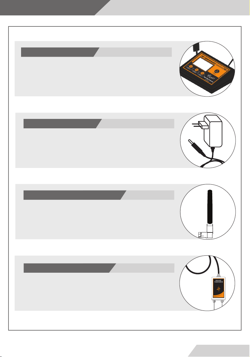
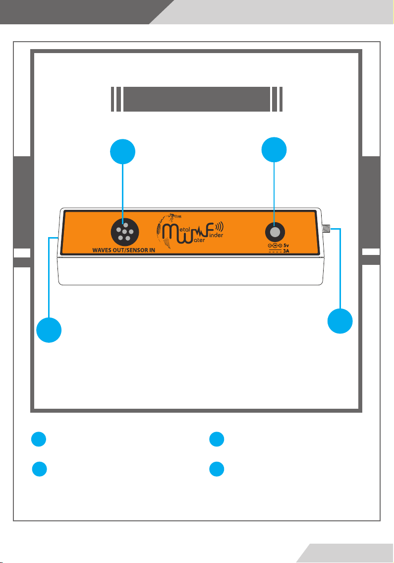
Device parts
Main Unit
The Main Control Unit for the device to set the search and device
parameters. Communicate with the other search systems via wireless
link.
Charge Adapter
This charger is used to recharge the battery, make sure the power
switch is on before starting the search or a screen would appear on
the display prompting doing so.
Ratings: input 100-240v DC 50-60Hz 0.4A - Output:5v AC 3A 15W
Wireless Antenna
Antenna for boosting the signal for transmitting the data to the
other search systems.
Ground Transmitter
Connect this unit to the Main unit and plant it in the ground to send
the waves and reinforce the signal.
The ground transmitter should be connected for both systems to
work.
Page
6
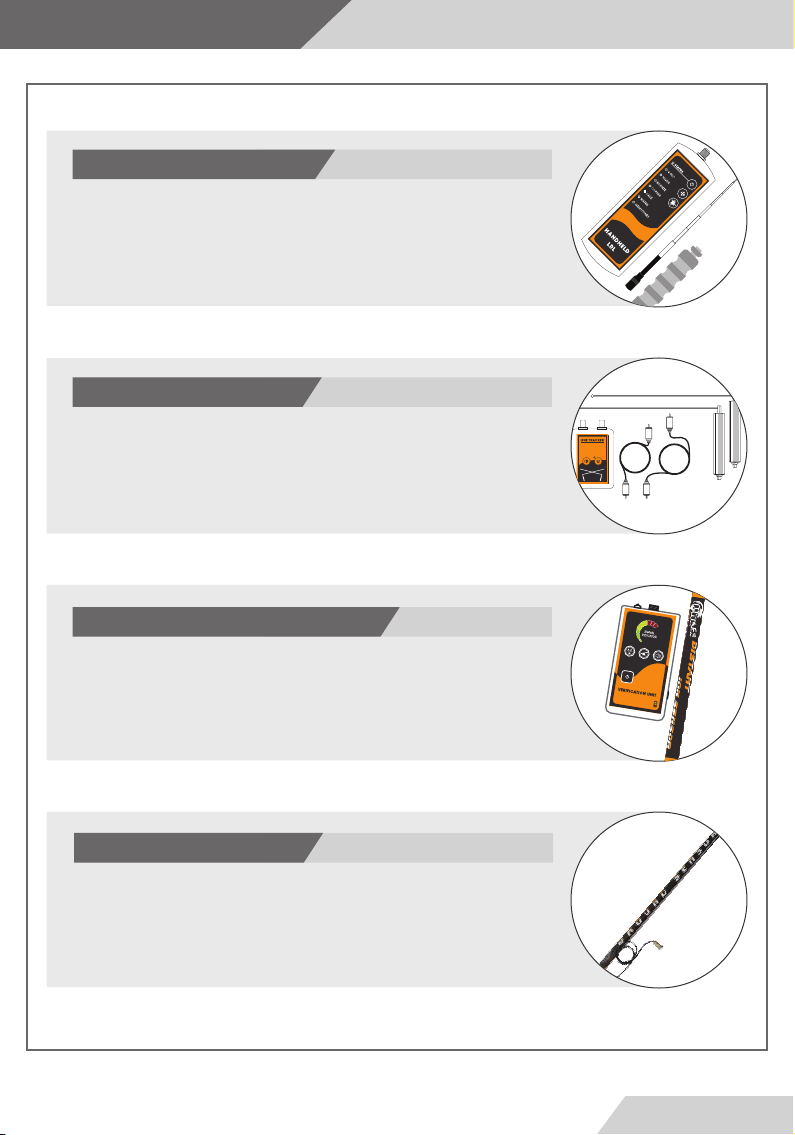
Device parts
Hand-held Unit
The LRL unit consist of the main unit, transceiver antenna, and the
grip.
The unit runs on 4xAA batteries.
Line Tracker and Antennas
Connect the cable to the rods and the Line Receiver.
Use this unit with the Line Tracking search method.
The unit runs on a 9v battery.
Verication Unit and iON Sensor
This unit is for detecting the ionic elds of the precious metals.
This unit is set by the Main Unit Wirelessly.
Ground Sensor
Connect to the Main Unit with the Ground Sensor System or Ground Scan System
to Measure the magnetic levels of the ground to determine and locate targets.
Equipped with high sensitivity sensors for best performance.
Page
7

Device parts
Headphones
Connect to the Main unit headphone jack or the
Verication Unit.
Page
8
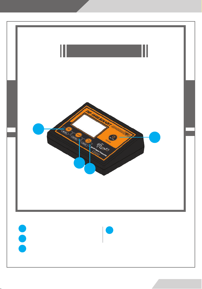
Main control unit
2
Front View
1
1
Power Button
Move Button
2
Enter button
3
3
4
Back Button
4
Page
9
Maine control unit
Back View
7
9
Charger Jack
7
Ground Transmitter Connector
6
86
Wireless antenna connection
Jack
9
Headphone Jack
8
Page
10

Maine control unit
2
Assembly
1
Connect Wireless antenna connection like drawing
1
Ground Transmitter Connector. Connect when using Long
2
Range Locator system or Line Tracking.
Page
1
2
11

Settings
Turn on the device by press and hold the power button in th front.
The device will start and show a loading screens
,Then show the main menu.
Note: The rst run for the device you will be prompted to choose
the system language.
Page
12
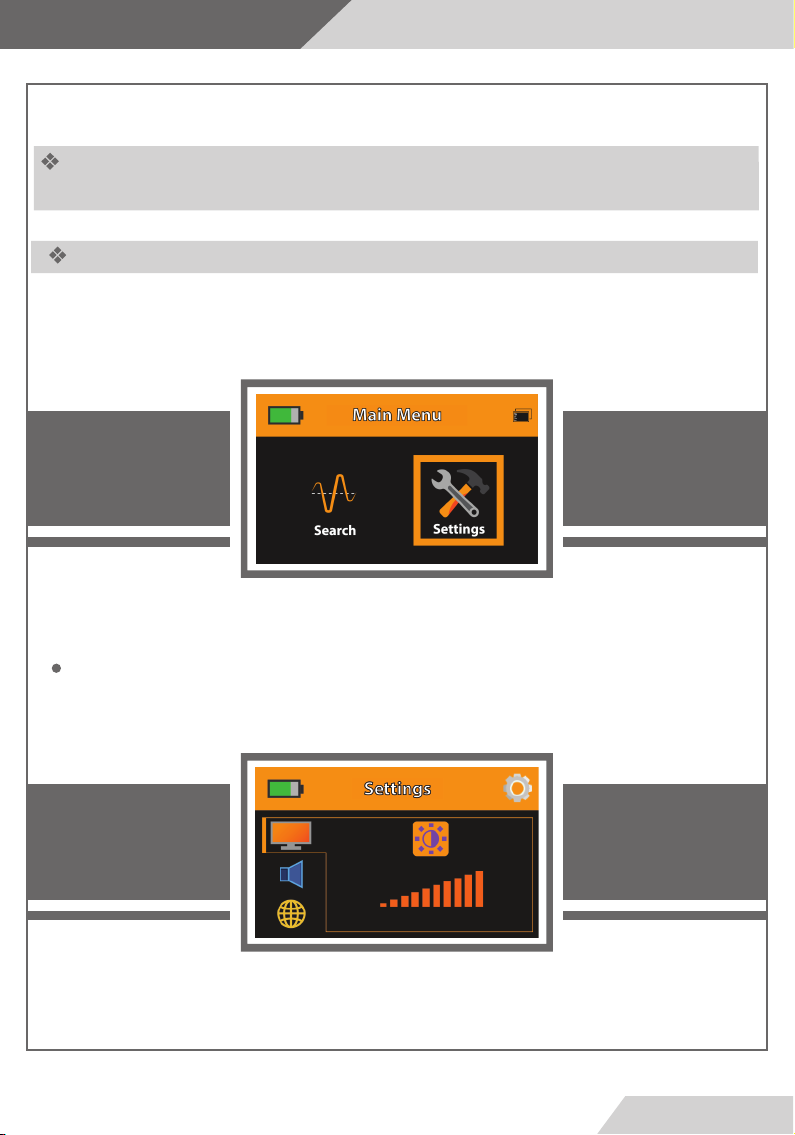
Settings
Use the (Move) button to navigate through menus on the display and press (Enter) to
select or conrm. Press (Back) to go to the previous Menu
Settings Menu
To access the Settings Menu select the gear icon in the Main Menu and press (Enter) to
the settings.
To set the screen brightness select the icon and press(Enter) to change the brightness
from 10% to 100%.
Page
13
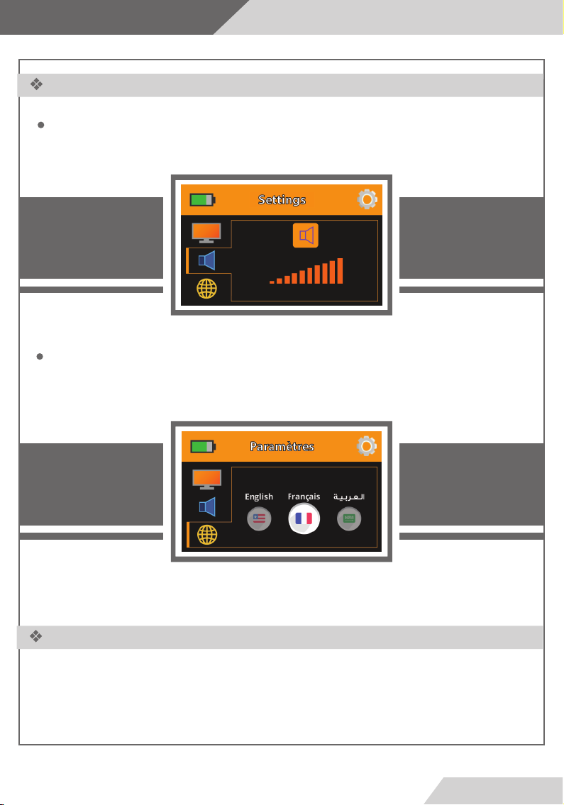
Settings
Settings Menu
To set volume select the Speaker icon and press (Enter) to change the Volume from 1
to 5 or mute.
To change the System language select and press(Enter) the device will load the
language and display the menus in the designated language.
تداﺪﻋا ﺔﻤﺋﺎﻗ
Press (Back) to exit the Settings Menu and go back to the Main Menu.
Page
14
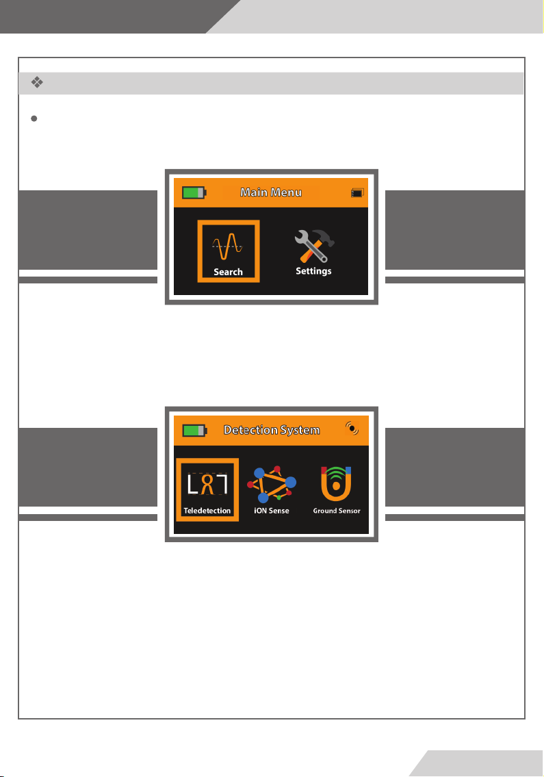
Settings
Starting the Search
To start the search process select the Search option from the Main Menu to access
the search systems.
The search systems will appear on the display:
Select the Long Range System
After selecting the Long Range System two options will appear on the screen (Line TrackingHand-held LRL)
These systems are the remote sensing methods.
Select a method to start with and press (Enter)
Page
15

Settings
: فاﺪﻫا ﻢﺋاﻮﻗ
Metal Meniu : contains the following objectives (Gold - Silver - Copper - Bronze)
Water Menu : contains the following objectives (All Type - Salty - Mineral - Natural)
Gem Menu : contains the following objectives (Diamond - Emeral - Meeority - All Gems)
Cavity Menu : contains the following objectives (Cavity)
Page
16

Settings
ﺚﺤﺒﻟﺎﺑ ءﺪﺒﻟا
After selecting the desired target type, the system will move to the list of criteria. Then
specify the distance and depth parameters by using the (Move) button to move between
the values of the distance and the depth
When you have finished selecting search options go to the start option and press the
(Enter) button to go and select the search method
Select the desired search method and press the (Enter) button to confirm
Note:
Make sure that the (Hand-held LRL) Unit or the ( Line Tracker) is turned on and
working before conrming the start of the search
Page
17

Settings
Select the desired search method and start searching
(Line tracker) search interface
(Handheld LRL) Search Interface
Page
18

Start work
Line
Tracking
Page
19

ﻂﺨﻟا ﺐﻘﻌﺗ مﺎﻈﻧ
Method of installation
Line Tracker and Antennas
1
2
3
4
5
Power Switch
Slide down to switch ON
Make sure the Tracker is o
before storage.
Status LED
Indicates the Line Tracker
connectivity
with the main unit.
Red = Disconnected
Green = Connected
Volume Button
Press to change the volume or to
mute the unit.
Speaker
in the back of the Tracker
Battery Compartment
To connect a 9VDC battery as
shown in the gure below
6
4
3
2
+-
5
1
Connect the rods to the antennas then connect the unit in the top to the antennas by the attached
6
cable.
Page
20

ﻂﺨﻟا ﺐﻘﻌﺗ مﺎﻈﻧ
Start work
Soil
1 3
4
2
Target
The Target is aected by the earth electrostatic and magnetic elds
1
The tuning and transmitting unit transmits a electro-frequency waves to determine target
2
location
The out waves spread through the earth which stimulate the formed elds around the target
3
identify it and forming a power lines
The line Tracker device receives the power lines that connected to the target to determine the
4
location
Page
1
21

ﻂﺨﻟا ﺐﻘﻌﺗ مﺎﻈﻧStart work
If you selected the Line Tracking search method, make sure that the Line Tracker is switched on and
the indication LED is on then the Main Unit will send the start command to the Line Tracker with the
selected parameters.
Note:
If there is Target, the device would form a frequency power line between the Target and the device.
If there is no target in the search area there would be no connection between the device waves and
the selected target type.
Soil
Location
Soil
Target
If there is Target, power lines would be
formed by the device and the target
If there is no target the device would not
form any power lines
Page
22

ﻂﺨﻟا ﺐﻘﻌﺗ مﺎﻈﻧ
Start work
Then rotate around the ground transmitter unit
A-If there is target in the search area a signal will be received which represented by the intersecting of
the antenna at some point which is the power line direction point between the device and the Target
location.
B- but if the user rotates a full circle and no intersection happened,then the selected search target
does not exist in the search area.
AB
No Target Exists
There is Target
Tuning and
Transmitting
Unit
2 M
Page
23

ﻂﺨﻟا ﺐﻘﻌﺗ مﺎﻈﻧ
Start work
How to locate Target (Stage one):
After setting and conguring the receiving device for search. fasten the Line Receiver Device on the belt
or put it in pocket then measure a two meters distance from the ground transmitter unit which
transmits the waves then hold the receiving antennas horizontally to the ground. hold an antenna in
each hand with a 25 cm distance between and make sure that the right antenna is 2 cm above the left
antenna as shown in gure
2 CM
20 CM
Tuning and
Transmitting
Unit
2 M
Page
24

Start work
ﻂﺨﻟا ﺐﻘﻌﺗ مﺎﻈﻧ
when passes the target point there
will be no more intersecting again
which means that the antennas are
beyond the target point and they
will turn back .
walk and track the power line
through the intersection of the
antennas over the power line
the midpoint between the last
intersecting point and the rst
rotation point is the target point
The antennas will intersect towards
the power line leading to the Target
location
the antennas will get parallel and
open when exit the power line
Rotate around the device
with 2 meters radius
Page
25

Start work
Hand-held Long
Range
Locator
Page
26

لﻮﻤﺤﻤﻟا ﺚﺣﺎﺒﻟا مﺎﻈﻧ
Start work
2
Hand-held LRL Unit
1
Transceiver Antenna
2
Handling Grip
3
1
3
Page
27

لﻮﻤﺤﻤﻟا ﺚﺣﺎﺒﻟا مﺎﻈﻧ
Method of installation
1
2
-
+
-
+
+
-
4xAA
Batteries
Plug the antenna to the jack in
1
front of the Handheld LRL Unit.
Connect the grip to the socket
2
in the bottom of the Unit.
Put 4xAA Batteries in the battery compartment
3
and pay attention to the polarity.
Note:
For the best product life use High quality batteries and remove them before storage.
+
-
Page
3
28

لﻮﻤﺤﻤﻟا ﺚﺣﺎﺒﻟا مﺎﻈﻧ
Start work
7
1
6
5
Antenna Jack
1
Status indicator
5
2
3
4
Power Button
2
Target Selection Button
3
Laser Button
4
Target LEDs
6
Laser Pointer Out
7
Page
29

لﻮﻤﺤﻤﻟا ﺚﺣﺎﺒﻟا مﺎﻈﻧ
Start work
The user must carry the device by grip horizontally slightly sloped towards ground as shown in
the gure below
Soil
Then stimulate the device’s waves and output elds by moving the device right and left slowly
then stop the device.
Left
Right
Moving sideways
Page
30

لﻮﻤﺤﻤﻟا ﺚﺣﺎﺒﻟا مﺎﻈﻧ
Start work
In the case of a located target , the device will receive signal and a reading that will divert the
device from the normal track to another track which is the target point track,
then the device will steady at the same direction ,in the meantime rotate fully around the direction
that the device went toward until reaching the opposite and notice the track change once more
and go toward the target.
then get 30 m sideway from the rst reading point and stimulate the device’s waves and steady the
device and wait for the result if the target is legit the device will rotate towards the same point
again therefore the target have been conrmed.
For more accurate reading and determining repeat the step from dierent points , and if all the
tracks intersect in a point then it is the target point.
2nd Reading
3rd Reading User
User
1st Reading
User
Target
To conrm after the target location, select a lower space value and repeat the previous steps.
Intersection
Point
Page
31

لﻮﻤﺤﻤﻟا ﺚﺣﺎﺒﻟا مﺎﻈﻧ
Start work
How to Locate Target
Initially the user must direct the scanning antennas down slightly towards the ground.
After ensuring multiple readings towards the target. Start walking in the same direction holding
the device normally . until you reach the passing point you will notice that the device rotates
around the normal track towards the point. Rotate with device slowly and start walking towards
the target slowly until you reach the point where the device rotates right and left then you have
located the target point.
Soil
Device rotates around the track
when passes the target point
Target
Page
32

لﻮﻤﺤﻤﻟا ﺚﺣﺎﺒﻟا مﺎﻈﻧ
Start work
There is another way to locate the target point more accurately, (Square method) take 4 dierent
readings for the target from 4 angles forming a square 3 m from target point the intersection
point of the for readings is the target point.
User
User
Device Direction
Device Direction
Target
Device Direction
Device Direction
User
User
The user can see the approximate depth of the target by going back to the main menu, Select the search
settings again, and changing the depth level through the depth list. For example, if the depth specied is
the rst time 5 meters we reduce the depth to 3 meters and enter the information, And we move away
from the target location 20 meters and carry the device and wait for reading the target location, if there
is a reading of the target site here we know that the depth may be between 3 meters, and we do this
process to reduce the depth until we know the approximate depth of the target.
- Second method of depth determination:
After conrming the point of the target, we reduce the search distance to the lowest level and
maintain the depth of the search to the highest level and complete the steps of work, and stand in
the detection unit specied above the target directly and we go in a dierent direction of the
transmission unit at medium speed until the unit circumvent the target location and measure the
distance resulting from this The point to the target location is the depth of the target
Page
33

Start work
How to Locate Target Debth
Different direction of the broadcasting unit
Medium speed
The device turns off
Towards the target location
Target
This distance is equal to the depth of the target
The depth of the target
Page
Soil
34

Start work
iON
Sense
Page
35

ﻲﻧﻮﻳا ﻒﺸﻜﻟا مﺎﻈﻧ
Start work
Verification Unit
This unit will detect the buried metals by sensing
the ionic fields that formed around the metal in
which the sensor will locate the metals location and
beep in the area of the detected field.
This unit implement the ionic detection system. In
which the device will identify the metals and burials
ions underground that formed from being buried for
a long period of time
Search Operation: Metals and Burials Detection
Search System: iON sense
Operating Processor: Microcontroller
Processor Frequency: 20.000 MHz
Processing Type:
Indicators:
Digital Signal Processing ( DSP )
Visual indicator (10 Bargraph LED) and Sound Indicator
Page
36

ﻲﻧﻮﻳا ﻒﺸﻜﻟا مﺎﻈﻧ
Start work
If you selected the iON Sense search method, make sure that the Verication Unit is switched on and
the indication LED is on
Select the target type for the search from the target menu then press “Enter”.
Then press Start “Enter” again to conrm the target and start the search.
The “Verication Unit” will switch on and set to the selected target from the main unit wirelessly.
Note:
Make sure that the verifaction unit is switched on and within distance.
Page
37

ﻲﻧﻮﻳا ﻒﺸﻜﻟا مﺎﻈﻧ
Start work
2
3
4
1
6
7
8
iON Sensor Connector
1
Flash LED
2
Visual Signal indicator
3
Power button
4
Battery indicator
5
5
Flash LED button
6
Volume button
7
Calibration button
8
Page
38

Start work
ﻲﻧﻮﻳا ﻒﺸﻜﻟا مﺎﻈﻧ
12
9
Speaker out
9
Power Switch ON/OFF
10
DC in 5v-3A
11
iON Sensor: Connect to the iON Connector (1)
12
10
11
Page
39

Start work
ﻲﻧﻮﻳا ﻒﺸﻜﻟا مﺎﻈﻧ
Power button: Press and hold to turn on the unit after
switching the power switch ON.
LED ashlight button: press the button to turn the
ashlight in the front of the unit for ease of use in night.
Keep in mind that working with ashlight increases the
power consumption and therefore less working hours.
Volume button: press the button to select the sound level
Ground calibration key: With this key, the user can adjust
the unit to adapt to the terrain and environment in which
the device operates. The device gives the normal and
stable adjustment of the search tool for better results.
Note: We may start searching in an area where the device
is issuing a signal in general
We press the calibrate key once and wait for the signal to
stabilize
If this continues to sound in any direction we press the
key again until we get a stable result and then go to the
search area to determine the targets.
There are three levels to adjust the calibration if the
device is not calibrated. You are located in areas where
there is high noise from high voltage, etc.
Page
40

ﻲﻧﻮﻳا ﻒﺸﻜﻟا مﺎﻈﻧ
Start work
To use the Verication Unit ,First move away from suspected target
location and calibrate the device by pressing the balance button, then
start moving around the target location. The unit will react according to
the target ionic eld indicating sound and visual signals.
The signal will increase when the unit is near the target.
Note:
The ionic eld intensity depends on the metal type and the period
that been underground.
Note:
The approximate depth of the target can be determined by using this
unit. After the target point is determined, direct the target to the
target and walk in any direction until the acoustic indicator is discon-
nected. We measure the distance from this point to the target point,
which is the approximate distance to the depth of the target.
Soil
Target
Audio Indicator
Level
Visual Indicator
Level
Page
41

ﻲﻧﻮﻳا ﻒﺸﻜﻟا مﺎﻈﻧ
Start work
Caution
-Charge the battery immediately after use.
-When the battery is full disconnect the charger.
-Only use the charge adapter that is attached with the prod-
uct.
-Charge and store the unit away from ammable objects.
-Turn the unit o after use and don’t leave it idle.
Description
LED
Indicator
Battery Status while workingBattery Status while charging
Description
LED
Indicator
Flashing Red: The battery is
starting to charge in rst stage
The red indicator stops ashing and the
yellow start to ash indicating the start
of the second stage of the charging
process
The yellow indicator stops ashing and
the green start to ash indicates the
third and nal stage of the charge
process
All lights on full battery charge
achieved disconnect the charger
Charge Adapter for the Verication Unit :5V DC / 3-A 15W
Battery at 100%
Battery at 50%
Battery at 25%
Flashing Red: The battery is low
and the unit will shut-down
automatically
Page
42

Start work
Ground Sensor
Page
43

ﻲﺿرا ﺮﻌﺸﺘﺴﻤﻟا مﺎﻈﻧ
Start work
Ground Sensor System
The Ground Sensor System works on scanning the soil layers and
identifying the contents by reading the magnetic elds to determine
and locate the metals and voids underground.
A smart User Interface with all the needed data and ease of use about the
search process
Discimination system to dierentiete between metals and voids
Waveform logging to keep track of the target size and place
Advanced sensors to provide instant results in real-time
Accurate obtaining to the target point with on screen display.
Search System:
Search Principle:
Frequencey:
Search Results:
Ground Sensor
Sensing the magnatic elds of the target and display the
results i real-time
Magnatic Measurement
Visual and audio signals with indicators in addition to
waveform for logging
Page
44

ﻲﺿرا ﺮﻌﺸﺘﺴﻤﻟا مﺎﻈﻧ
Start work
To start working with the Ground Sensor System go to main menu then select the system
and press (ENTER) to go the system interface.
If the Ground Sensor is not connectoed, a notication will appear on the display indicating that the user must connect the Ground Sensor to continue working with the system.
Page
45

ﻲﺿرا ﺮﻌﺸﺘﺴﻤﻟا مﺎﻈﻧ
Start work
Connect the Ground Sensor plug to the sensor in jack in the back of the Main Unit as shown in
the gure below.
A notication will appear on the display indicating that the Ground Sensor has been connected
successfully. As shown in the gure below.
Page
46

ﻲﺿرا ﺮﻌﺸﺘﺴﻤﻟا مﺎﻈﻧ
Start work
To start the scanning process put the carrying belt across the shoulders and
hold the Ground Sensor 15-20 cm away from the earth surface perpendicularly to the earth.
Soil
Before starting the user has to balance the device and adjust the sensitivity according to the
ground by pressing ENTER or the Button on the top of the Ground Sensor to take a balancing
measurement in a stable place unaected.
The ux density is aected by the location of the search so in dense magnetic ux areas the
readings will indicates to a false metal readings.
It might be necessary to take several balancing measures due to dierent soils and layers might
have dierent ux elds.
15 - 25 cm
Page
47

ﻲﺿرا ﺮﻌﺸﺘﺴﻤﻟا مﺎﻈﻧ
Start work
The user has to walk toward the search area holding the Ground Sensor, After making a balance
measurement.
The results of sentivity will appear on the display in Real-time.
123
ﺔﺑﺮﺘﻟا
Void
Metal No Target
Page
48

ﻲﺿرا ﺮﻌﺸﺘﺴﻤﻟا مﺎﻈﻧ
Start work
A stable indicator in the middle range indicates no targets in the search area.
Void
In case of metal target in the search are the indicator will show a high values in the
high range of the display .
An increasement in the waveform above the midline will indicate the sensitivty of the
target showing the contours of the target dimensions and size
Void
Void
Page
49

ﻲﺿرا ﺮﻌﺸﺘﺴﻤﻟا مﺎﻈﻧ
Start work
In this case the existing target is void and the interactive indicator with high values of blue
according to the received signals and the target size in the search area
A dirential signals on the waveform will show the an increasment over the midline when cavity
is sensed and the waveform would decrease below the midline after passing the target which
will give the user an estimation of the cavity or void size and dimensions.
Void
Page
50

The Charge
Notes:
-The device will make a beeping sound when the battery is full and the charging is done, so
disconnect the charger when the notication is heard.
-An indicator will show the charging progress in the upper corner while the device is working.
-To ensure the performance of the device is kept in best state, Turn the device o and remove
any batteries before storing.
Page
51

Notes
Page
52

Metal and Water Finder
United States of America - illinois
www.mwf-usa.com
info@mwf-usa.com
+1 ( 708 ) 364 9602
Turkey - istanbul
www.mwf-metaldetectors.com
info@mwf-metaldetectors.com
+90 ( 212 ) 222 0946
+90 ( 212 ) 222 0947
 Loading...