

Page 1

Operating instructions
MVVS 26 IFS no.: 3094I
MVVS 35 IFS no.: 3098I
MVVS, spol. s r.o.
tř. Kpt. Jaroše 35
60200 Brno
Czech Republic
Version 1.3
Page 2
Congratulations on choosing the gas engine MVVS 26 ccm (35ccm).
MVVS 26 and 35 has been designed and manufactured for propeller-powered radio-controlled model planes. It is able to
meet all of your expectations of an acrobatic racing engine.
Before using the engine, carefully read these instructions
MVVS 26ccm
Bore
Stroke
Weight of complete engine
without ignition*
Weight of ignition unit
RpM range
MVVS 35ccm
Bore
Stroke
Weight of complete engine
without ignition*
Weight of ignition unit
RpM range
* The value in the table above stands for the weight of a completely assembled engine, including the spark plug,
carburetor, drive washer and prop screws.
** Power output varies with the exhaust used. The value given in the table stands for the maximum available power
output.
33 mm
30.1 mm
936 g
165 g
1400 – 9500
35.5 mm
35.2 mm
1493 g
165 g
1400 – 9000
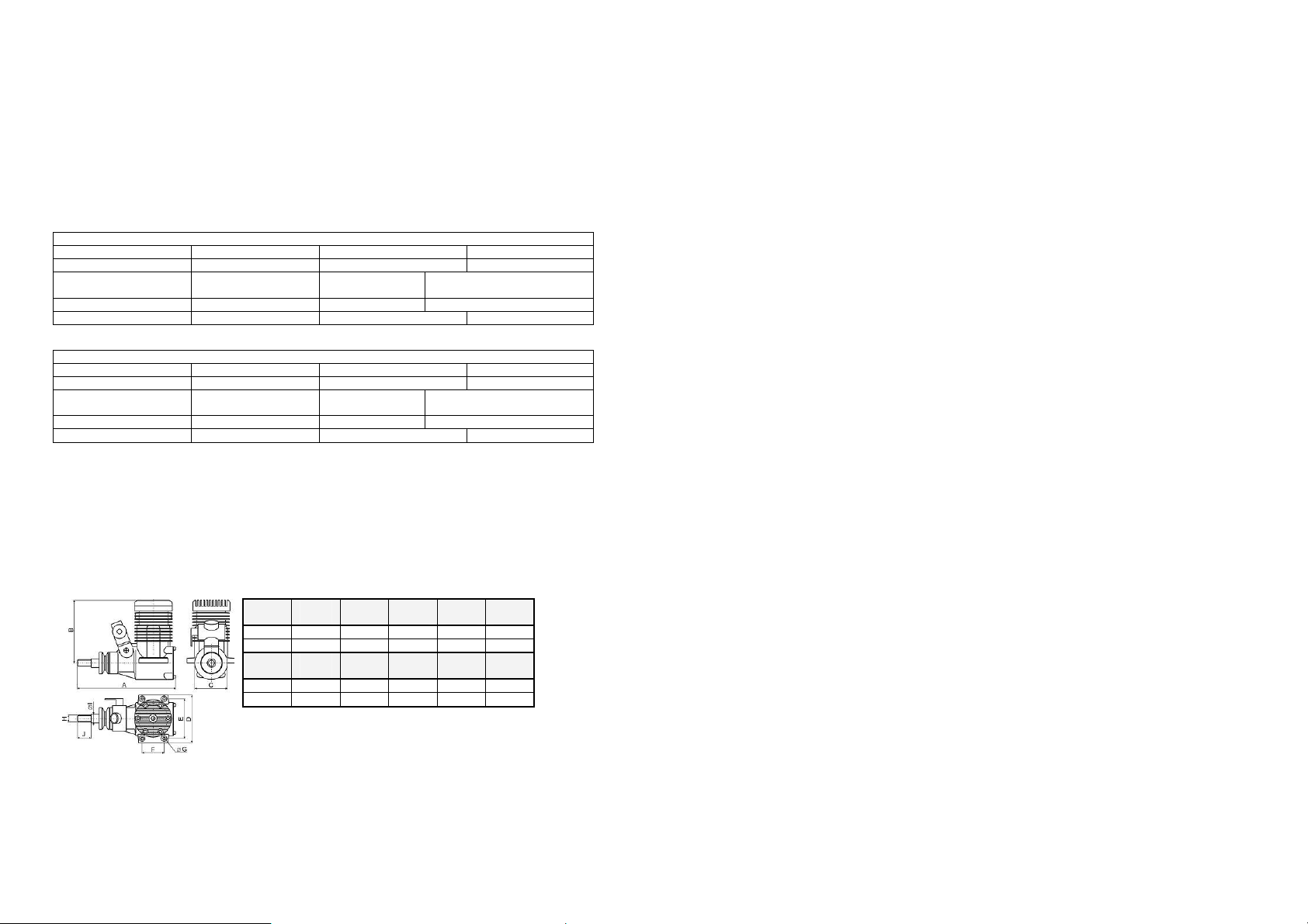
Engine’s dimensions
Technical specifications
Maximum power output **
Maximum torque **
Fuel
Lubrication
Maximum power output **
Maximum torque **
Fuel
Lubrication
A
mm B mm C mm D mm E mm
26 IFS 146 99 50 70 60
35 IFS 182 118 60 84 70
F
mm G mm H mm I mm J mm
26 IFS 31 4,3 M10x1 10 33
35 IFS 41 5,3 M10x1 10 45
Unleaded 95-octane fuel
Oil with petrol in mixture 1:40
Unleaded 95-octane fuel
Oil with petrol in mixture 1:40
2
3.8 PS/9000 RpM
3.1Nm/8000 RpM
4.1 PS/8500 RpM
3.8 Nm/7500 RpM
Notes:
11
Page 3

Notes:
10
Safety precautions:
1) Never use the engine for any manned vehicles.
2) When operating model planes, always follow the rules and laws in effect in your country.
3) The manufacturer declines all responsibility for all damages arising from the operation of models and other
appliances droved by MVVS engine.
4) Always use original spare parts.
5) Never tamper with the engine construction.
6) Before each flight check that all the propeller screws are tightened up and in good condition. If you use a
spinner, check that it is tightened up, too. When mounting the spinner always follow the assembly
instructions.
7) Before each flight check that all the propeller screws are tightened up and in good condition. If you use a
spinner, check that it is tightened up, too. When mounting the spinner always follow the assembly
instructions.
8) Periodically check that the engine is firmly fixed to the engine mounts. Never start a loose engine!
9) Always use a balanced propeller! Always replace the propeller when damaged!
10) Make sure that no part of your body intersects the plane of the spinning propeller.
11) Always wear close-fitting, well-fastened clothes when starting or operating the running engine. Never wear
loosely hanging clothes (ties, scarf, etc.).
12) Never try to stop the engine by any part of your body.
13) Always stop the engine either by turning off the ignition switch or by completely closing the carburetor
throttle valve.
14) Before starting the engine always make sure that the model is safely fixed in place and cannot start moving.
15) Fuel is combustible and therefore must be kept in an enclosed container at a safe distance from the engine
when it is running.
16) When preparing fuel carefully follow the manufacturer’s or dealer’s instructions.
17) Small objects must be kept at a safe distance from the engine when it is running. Never throw any objects
towards the spinning propeller.
18) Be careful in choosing the location where you wish to start the engine. Avoid dusty or sandy areas.
19) Start the engine in well-ventilated areas only. Never start the engine indoors.
20) When starting the engine make sure that bystanders, especially children, are at a safe distance of at least 10
meters.
21) The engine power output makes it possible to fly big models. Mal-operation of such models may cause
serious damage. Start using the MVVS 58 in model planes only after you have mastered operating smaller
It is usually the case that propellers of the same dimensions coming from different manufacturers are not the same.
Oftentimes not even propellers of the same dimensions produced by a same manufacturer are not the same. The engine
power is best utilized when the propeller dynamics curve and engine power curve (revolutions / power output) intersect
in the area of the engine top power output. Unfortunately, no propeller manufacturer provides this information. Engine
power output is also a variable quality. It depends above all on the silencer used and can considerably vary. The situation
is further complicated by environmental parameters (temperature and atmospheric pressure in particular): low
temperature and high pressure increase propellers’ input requirements by 20% in comparison with input at hot weather.
MVVS 26 and 36 has been designed to generate maximum power at 8500 RpM, according to the type of exhaust used. If
you wish to utilize the maximum power output, choose a propeller which allows the engine to reach these revolutions, or
slightly lower revolutions (given the unloading of the propeller depending on the speed of flight) on the ground.
We do not recommend to use propellers with which the engine reaches more than 9000 RpM. on the ground.
models.
Selecting a suitable propeller
Suggested propeller dimensions:
MVVS 26: MVVS 35:
16x8, 16x10, 16x11, 16x12, 17x8, 17x10, 17x 12, 18x8 18x8, 18x10, 20x8, 20x10, 20x12,21x8, 21x10
3
Page 4

Always use unleaded 95-octane petrol mixed in the proportion 40 volume units of petrol to 1 unit of Mobil Racing 2T
oil. If necessary, quality brand-name synthetic oil intended for racing two-stroke engines can be used too.
Mix it in the proportion 30:1.
Never use inexpensive oil developed for garden appliances or synthetic oils intended for the operation of methanol
model engines. The manufacturer declines all responsibility for all engine damages arising from the use of low-quality
fuel.
Fuel
Assembly
The engine is fastened in place with four holders built in the rear cover. The rear cover is adjustable by 90° which
ensures easy access to the carburetor’s operating elements. The engine can be mounted directly to the firewall or an
assembly kit can be used (special accessories). Use M6 screws or screws M4 with a reduction kit (special accessories). If
you decide to fasten the engine using flexible motor mounts, always choose parts with enough solidity and strength.
Make sure to secure the screws against loosening and regularly check that they are tightened up and in good condition.
Since air is used to cool the engine, sufficient air circulation under the cowl must be ensured. Never forget about a hot air
outlet – which must be bigger than the intake. Gas engines heat up to a much greater degree than methanol ones!
Do not forget that the engine needs oxygen from the air to be able to operate. Therefore ensure access of air to the engine
intake as well. Caution: intake of warm air from beneath the cowl may cut the engine power output.
Caution!
When mounting the engine in the model use seals to protect all openings and prevent the pollution of the engine’s
inside with sawdust, residual abrasives etc.
Exhaust
Use only factory-made exhausts pipes designed for this type of engine, preferably brand-name MVVS engines with
which you also get the power output guaranteed.
The manufacturer declines all responsibility for all engine damages arising from the use of improper exhaust systems.
When mounting the exhaust follow the manufacturer’s instructions. Make sure to secure sufficient cooling of the
exhaust.
3298/26 (3298/35) – ultra compact, the lowest power output
3270 (3271) – compact, medium level of power output
3266 (3268) – tuned pipe, with adaptor 3265 (3269) provides the highest power output, with the flat torque curve, useful
for the model planes
3266
3268
3298/26 - 3298/35 3270 - 3271 3265 -3269
4
The MVVS gas engines come with a two-year guarantee against defects in workmanship and materials. Only original
buyers of the engines are eligible warranty claimants. The warranty cannot be transferred with a change in ownership.
This guarantee does not cover:
Produced by: MVVS, spol. s r.o., tř. Kpt. Jaroše 35, 60200 Brno, Czech Republic
- any normal wear that might occur
- damage arising from accidents
- damage arising from the use of an unbalanced or damaged propeller
- damage arising from the use of a too small or a too big propeller
- damage arising from the use of low-quality fuel
- damage arising from the use of other than original spare parts and accessories
- damage arising from sucking a foreign object into the engine
- damage arising from any improper use
Ph.: +420 545 211 683, fax: +420 545 211 418
E - Mail:
mvvs@mvvs.cz
Http: www.mvvs.cz
Warranty
Certificate of Warranty
Date: Serial Number:
Dealer: Buyer’s name and address:
9
Page 5

No: Description:
0101 Crankcase
0304 Pressure nipple
0202 Front bearing
0203 Rear bearing
0301 Rear cover
0302 Rear cover screws - set
0303 Rear cover „O“ - ring
0501 Cylinder head
0502 Cylinder head screws - set
0503 Cylinder head gasket
0650 Cylinder-piston assembly
0701 Piston
0702 Piston ring
0801 Piston pin
0802 Piston pin circlips
0901 Connecting rod
Spare parts list
No: Description:
1001 Crankshaft
1101 Drive washer
1102 Drive washer key
1103 Propeller nut
1104 Propeller washer
1106 Drive washer shim
3224 Carburetor
0306 Carburetor flange
0305 Isolation underlay
0307 Carburetor flange gasket
1307 Carburetor screws
3309 Spark plug
3314L Electronic ignition unit
1405 Ignition sensor fixing screws
8
Carburetor adjustment:
Basic setting:
(Minutes refer to hands of a clock)
The new engine comes adjusted to the basic setting. This setting should be kept during running the engine in!
After the engine has been run in, adjust it following the instructions below:
- start the engine and warm it up
- let the engine run at idle speed for approx. 5 seconds
adjusting needle ( L ) for low RpM range 1turn and 50 minutes
adjusting needle ( H ) for high RpM range 1 turn and 35 minutes
adjusting needle ( L ) for low RpM range 1turn and 45 minutes
adjusting needle ( H ) for high RpM range 1 turn and 45 minutes
for WT 481
for WT 561
Step I
engine accelerates quickly and without a hiccup go to Step III. If acceleration is not smooth go on to Step II.
Step II
- Faulty acceleration with hiccups and a tendency to cut out is usually attributable to a poor fuel mixture in
the medium-revolutions range. Stop the engine and recheck the fuel feed (the hose-pipe must not be pinched or broken;
if fitted, check also the fuel filter permeability). Restart the engine and test acceleration again. If problems persist adjust
the carburetor. Open the adjusting needle L by 5 min and retest acceleration. If acceleration is smooth, open the needle
by another 3-5 min - this should be done because the needle was previously set at a boundary value; if atmospheric
conditions changed during flight, the problems might recur.
If the engine continues to not accelerate properly open the low speed needle by 10 minutes. If the engine’s
operation does not improve, shut it off and check the basic setting. Set the adjusting needle L at 1 turn and 50 min and
the adjusting needle H at 1 turn and 10 min., restart the engine and test the acceleration. If the engine runs correctly go to
Step III. If it continues to not accelerate properly, open the low speed needle by another 10 minutes. If acceleration is
faulty, the defect is likely to lie somewhere other than an adjustment.
Step III
If the engine accelerates correctly, according to the above test, set it at idle speed and accelerate to full
speed. Repeat twice more. If the engine functions correctly, go to Step IV. If it cuts out, open the L needle by 5-10
minutes more.
If the engine does not respond to acceleration fast enough, keep closing the L needle until the engine starts
to cut out in response to throttle opening. At that point reopen the L nozzle by 5-10 minutes.
Step IV
successfully. If revolutions seem to drop, open the adjusting needle H by about 5-10 minutes.
Caution!!! The engine must be stopped while you adjust the carburetor in order to prevent injury by the propeller.
- Accelerate to 2/3 of the throttle range within approx. 1 sec (faster acceleration). Repeat three times – if the
If the engine reacts correctly set it at full speed. If revolutions do not drop, the engine has been adjusted
5
Page 6

Before you first start the engine, make sure that the plug is screwed in and tightened up and that the plug socket is fitted
in place and fastened down properly.
Fix the ignition sensor in proper position above the magnet with screws enclosed.
Unless the spark plug is inserted in plug socket, never turn the engine with ignition turned on.
This could lead to ignition damage!
1) Make sure that the ignition is switched off, the choke valve is closed and the throttle valve is about half opened. Then
give the engine 3-4 turns, provided that carburetor is not overflowing. If it is overflowing, only give the engine 1-2 turns.
2) Switch the ignition on, open the choke valve, set the throttle at slightly higher idle speed and give the engine a few
quickly turns. If even after the fourth turn, with the choke valve closed, you do not hear a suggestion of the engine
starting, give the engine 2 turns following the instructions in paragraph 1 above. Then proceed according to instructions
given in paragraph 2.
3) If the engine does not start even after another set of turns open the throttle to maximum and give the engine approx. 4
turns. Switch the ignition off and on again and restart the engine with throttle turned slightly down and the choke valve
set open.
4) If the engine still would not start, unscrew the plug and check its contacts. Clean any possible petrol moisture (i.e. an
indication of engine overflow) and screw it in again. Further starting should only be done with the throttle turned down.
If the plug is dry then probably not enough fuel has been drawn into the carburetor. If that is the case, check the fuel feed
and then return to the instructions given in paragraph 1.
Having started the engine, leave it running for about 5 minutes at a higher idle speed. Then run it in for about 20 min,
while changing revolutions from idle to 1/2-3/4 of the range and shortly holding each position - gradually prolong the
holding periods. After 10 minutes of operation, open the throttle at maximum for a period of about one minute. At this
point stop the engine and let it cool down. Then restart it and check the adjustment. If everything is all right, you can first
take off. During first few flights do not overload the engine and do not let it run at high revolutions for long periods of
time (very important at hot weather). Use up all fuel that was produced as a mixture with the oil that is included in the
package. From now on, fuel and oil should be mixed in the proportion 40:1.
The engine does not start:
You should get following results if the engine is settled up and in run correctly
These values are only approximate and may vary with the factors described in the previous section, as well as with the
type of the exhaust system used.
- check and possibly replace the spark plug (check the spark: put the plug into the cable end and by
turning the engine you’ll see the necessary spark. Note: The plug must touch a metal part of the
engine.)
- check the fuel lines.
- turn the engine to check its mechanical condition
- check that the carburetor nozzles are adjusted correctly
- remove the carburetor and visually examine the condition of the carbonfibre reed valve
- unscrew the carburetor cover on the side of the pressure inlet, check the fuel screen possibly give the
carburetor a blow with a current of air; when reassembling, make sure you arrange the membrane and
gasket in a correct order
- recheck the pressure hose attached to the carburetor
Engine Propeller RpM Silencer Engine Propeller RpM Silencer
26 IFS
APC 16/12 7300-7400 3266 APC 20/8 7600-7700 3268
APC 16/10 8100-8300 3266 Mejzlik 20/10 7200-7300 3268
Mejzlik 18/8 8100-8200 3266 Mejzlik 20/8 8200-8400 3268
7200-7300 3270 Mejzlik 21/10 6600-6700 3268
6700-6800 3298 Mejzlik 20/8 7100-7200 3268
Mejzlik 20/10 6300-6400 3271
Mejzlik 20/8 7300-7500 3271
Starting and running in a new engine:
Problem guide
35 IFS
Mejzlik 20/8 6700-6800 3298
6
Possible faults of the engine and how to dispose those
If the engine does not start:
- check and possibly replace the spark plug (check the spark: put the plug into the cable end and by
turning the engine you’ll see the necessary spark. Note: The plug must touch a metal part of the
engine.)
- check fuel lines
- check for proper mechanical function by turning the engine over
- check that carburetor’s nozzles are settled correctly
- remove the carburetor cover from the feed side; check the filter and blow off carburetor with
compressed air; (Caution: When using compressed air, use eye protection.) When re-assembling be
careful of maintain the proper order of the components
- check the vacuum feed line
Mechanical faults:
- If the engine can not be turned over easily:
- a likely cause is the piston in the cylinder is seized: loosen and unscrew the M5 bolts under the
cylinder (to loose the nuts use exclusively a special wrench which you can order as an accessory)
- carefully remove the cylinder
- visually examine the piston and crankcase to find the likely cause of the engine’s mechanical problem
- mechanical repairs must always be completed by a professional service department
Service suggestions
After each 20 hours of running or 1 year change the spark plug.
After 100 hours of operation time commit the engine to the professional service department for check-up.
Re-assembling
These operations are very complicated and it is not recommended to do it on your own. Please commit to professional
service.
Possible guide instructions we publish are as follows:
Demount rear cover, head and carburetor. It is not possible to re-assemble the engine unless the cylinder part of the
engine is heated up to 80° - 100°C. Then it is possible to remove steel piston insert without rotating (!). Next step is
piston and connecting rod removal. Crankshaft has to be in the top dead centre (TDC). Pull off the connecting rod from
pin on the crankshaft in direction to rear cover out of the crankcase. After getting off the drive washer and Woodruff
(safety) key, it is possible to pull out the crankshaft again in direction to rear cover out of the crankcase. You will get the
bearing out after heating up (again between 80°- 100°C). Assembling passes off in opposite meaning.
7
 Loading...