

Page 1
TECHNICAL MANUAL
REV:201509.01
Page 2
INSTALLATION, OPERATION AND CARE
OF MODEL AX-M60P
GENERAL
The AX-M60 planetary mixer is an advance design, highly reliable professional food processing tool,
and is ideal for mixing all types of dough as well as eggs, cream, mayonnaise, etc.
There are 2 speeds and various style attachments which can be selected. They are made of alloy
aluminum to meet with hygiene standard.
This model mixers is equipped with powerful 3 HP motors and strong gear drive design. The gears are
made of heat-treated alloy steel and a harnessed steel worm wheel.
If your operation and maintenance are correct, then it will give you years of service, and obtain the best
using result.
INSTALLATION
UNPACKING
Immediately before unpacking mixer, check it for possible shipping damage. If you find the packaging
material or the machine is damaged before unpacking, contact the carrier within 3 days of delivery.
Prior to installation, test the electrical service to assure it agrees with the specifications on the machine
data place located on the backside of the pedestal.
LOCATION
Place the Mixer in a convenient location, and allow working space on the hand-wheel or power bowl lift
switch side. All maintenance can be handled from this side, the top and the front. Set the mixer level
and use shims if the floor is uneven, the machined edge on the top of the transmission case makes an
excellent surface for leveling.
2
Page 3
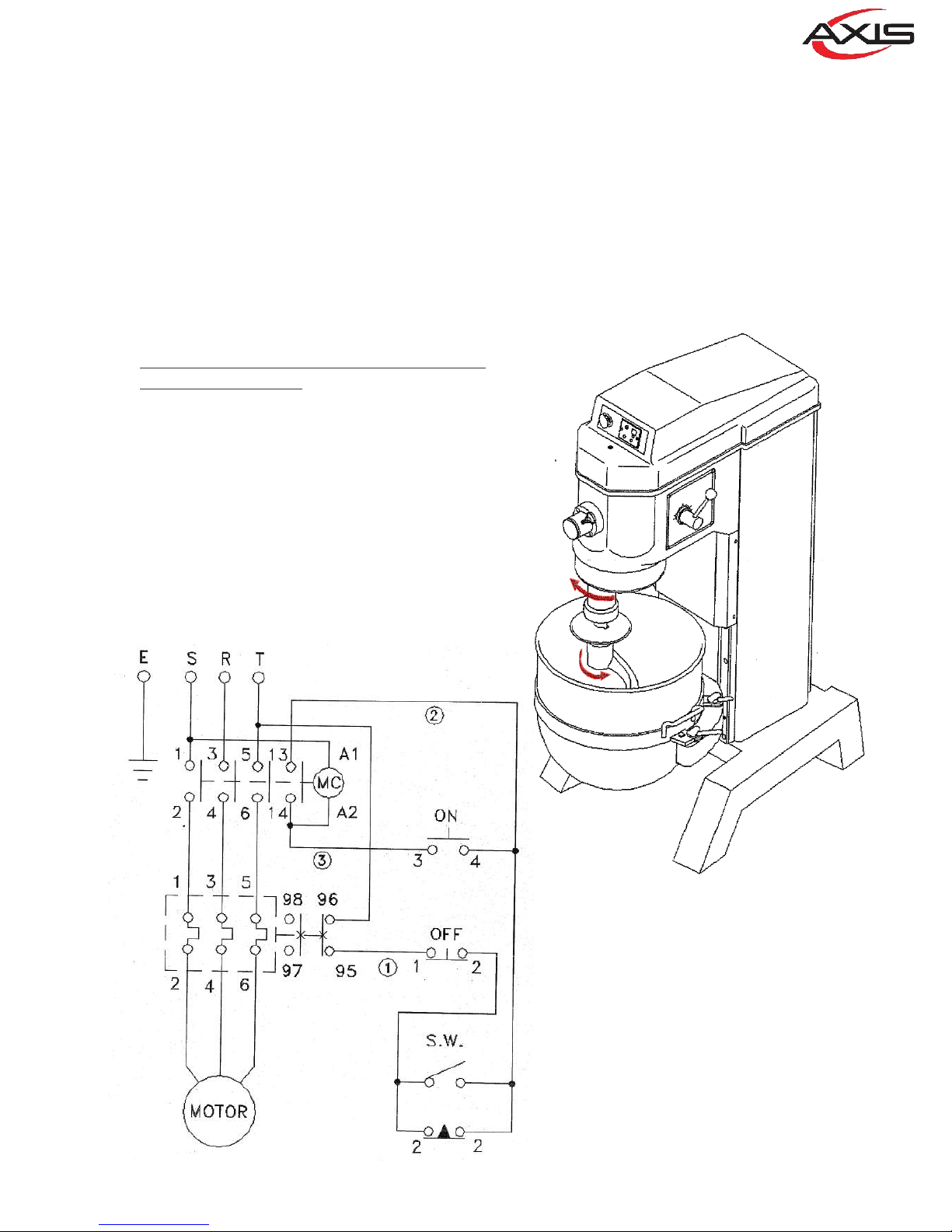
Electrical Connections (Cord Connected Mixers)
· Before making the electrical connections, read the specifications on the nameplate to
make sure that they agree with those of your electric service.
· Electrical connections should be made by qualified technician or electrician, who will
observe all applicable Safety Codes and the
National Electrical Code.
· Be sure the planetary runs in the direction
shown by the arrow in the planetary head.
Reverse direction is forbidden.
· To start motor, push ON button. The speed
selector handle must be at one of the
numbers indicating a speed, not at an
intermediate position.
On a 3 Phase Mixer, the installer must check the
mixing rotation of the planetary when the
electrical is connected.
3
Page 4
4
Page 5
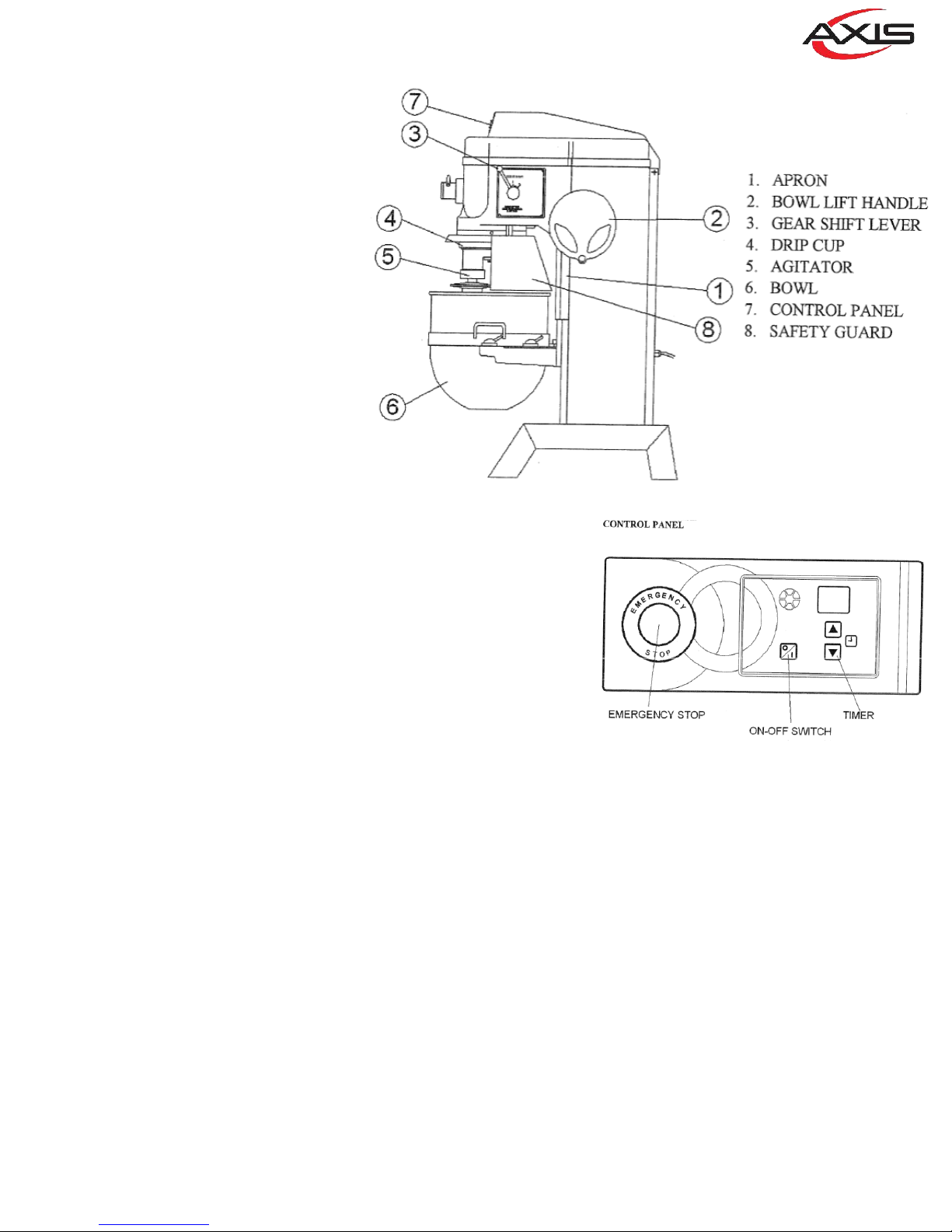
OPERATION
WARNING: MOVING PARTS,
BEATER OR HOOK IN BOWL; KEEP
HANDS, CLOTHING, AND UTENSILS
OUT WHILE IN OPERATION.
All models are furnished with two
buon-switches, which control
power to the mixer.
The GEAR SHIFT LEVER (No.3) is
used to change speed. Always stop
the mixer before changing speeds.
To change speeds, turn the switch
OFF, move the gearshi lever to
the desired speed, and turn the
switch back ON.
· Speed 1 (low) – This speed
is for heavy mixtures such
as bread dough, heavy
baers, and potatoes.
· Speed 2 (medium) – This speed is for light dough which
must rise quickly, heavy baers, and some whipping
operaons.
DOUGH HOOK:
To install the dough hook (No 5), the bowl must be installed and
fully lowered. Place the hook in the bowl, push it up on agitator
sha, and turn it clockwise to seat the sha pin in the slot of the
agitator shank.
It is frequently used for heavy bread dough, and preferable to be
use at low speed.
The moisture content of heavy dough is a crical when selecng
proper mixing speed. You should never use 2 speed when
nd
mixing heavy dough with an Absorpon Rao (AR) of 50% or
less.
BOWL – CAPACITY: 60 QUART
New mixers bowls and dough hook should be removed and thoroughly washed with hot water and mild soap
soluon, rinsed with either a mild soda or vinegar soluon, and thoroughly rinsed with clean water BEFORE
being put into service. This cleaning procedure should also be done daily or aer each use.
The bowl must be installed before the agitator. To install the bowl, fully lower the bowl support. Posion the
bowl so the alignment bracket on the back of the bowl is in the bowl retainer and the alignment pins on the
front of the bowl support fit in the holes on the sides of the bowl.
ATTACHMENTS
To install an aachment, loosen the thumbscrew on the aachment hub and remove the plug. Insert the
aachment into the aachment hub making certain that the square shank of the aachment is in the square
driver of the mixer. Secure the aachment by ghtening the thumbscrew.
Move the gearshi lever to the desired speed and star the mixer to operate the aachment.
The meat and food chopper aachment should be operated in second or third speed. If material in the cylinder
stalls the mixer, stop the mixer at once. DO NOT aempt to restart the mixer in a lower speed – remove the
adjusng ring, knife, plate, and worm and clear the obstrucon.
5
Page 6
MAINTENANCE
CAPACITY (QTS. LIQUID) 60 qt.
Egg Whites Wire Whip 2 qt.
Mashed Potatoes Flat Beater 40 lbs.
Mayonnaise (Qts. Oil) Flat Beater 18 qt.
Meringue (Qts. Water) Wire Whip 1.5 qt.
Waffle/Pancake Batter Flat Beater 24 qts.
Whipped Cream Wire Whip 12 qts.
Sheet Cake Batter Flat Beater 45 lbs.
Cup Cake Flat Beater 50 dz.
Layer Cake Flat Beater 70 lbs.
Pound Cake Flat Beater 55 lbs.
Sugar Cookie Flat Beater 100 dz.
Bread or Roll Dough (Light/Medium,
60% AR, =) Dough Hook 80 bs.**
Bread or Roll Dough (Heavy, 55% AR, =) Dough Hook 60 lbs.**
Pie Dough Flat Beater 50 lbs.
Thin Pizza Dough (40% AR, = , 5
min.max. mix time) Dough Hook 40 lbs.**
Medium Pizza Dough (50% AR, =) Dough Hook 70 lbs.*
Thick Pizza Dough (60% AR, =) Dough Hook 70 lbs.**
Raised Donut Dough (65% AR) Dough Hook 30 lbs.*
Whole Wheat Bread Dough (70% AR) Dough Hook 70 lbs.**
Egg & Sugar for Sponge Cake Flat Beater 24 lbs.*
* 1st speed ** 2nd Speed
* = If high gluten flour is used, reduce above dough batch size by
NOTE: All maintenance work should be done only aer unit has been disconnected from electrical power
and grounding.
CLEANING
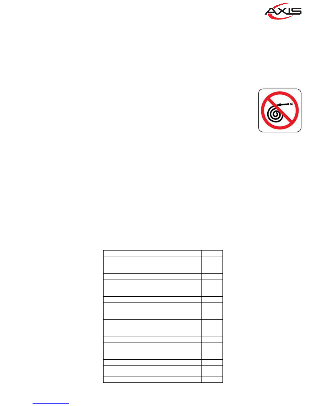
Never use a metal or sff brush to clean mixer. Never clean the mixer with a water hose
or any fluid under pressure.
The mixer should be thoroughly cleaned daily.
Bowl and agitators should be removed from the mixer and cleaned in a sink.
The transmission case and planetary mechanism should be inspected weekly for leaks,
damage, etc. should it become necessary to repack the ball bearings; an authorized
service technician or the manufacturer should be contacted. Use of unapproved grease of
lubricants may lead to damage and void the unit's warranty.
The bowl li track should be lubricated semi-annually, or more oen under heavy usage. Disconnect the unit
from power supply before removing the top housing or apron. The drip cup (Fig. 1)? should be inspected
periodically for moisture or lubricant dripping. Remove the cup and wipe it with a so cloth.
DO NOT use a hose to clean the mixer – it should be washed with a clean damp cloth.
MIXING HEAVY DOUGH
The moisture content of heavy dough is a crical factor when selecng proper mixing speed. You should never
nd
use 2 speed when mixing heavy dough with an Absorpon Rao (AR) of 50% or less.
To determine the Absorpon Rao (AR) of a product, divide the water weight by the flour weight.
Example: Calculate the Absorpon Rao of a mixture containing 10 lbs. of flour and 5 lbs. of water.
10 ÷ 5 = 0.50 = 50% = AR
6
Page 7
1
01
7
Page 8
Description or Name Parts No. Qty
TOP COVER
1
RETAINER- MAIN SHAFT
2
RETAINER- TRANSMISSION SHAFT
3
GEAR HOUSE COVER
4
TRANSMISSION CASE
5
SUPPORT TO TOP COVER
6
SCREW
7
SPRING WASHER 1/2"
8
COVER PLATE
9
SCREW
10
BOLT 5/16*3/4
11
BOLT 3/8*1- 1/4
12
SPRING PIN 6*28
13
11091-01-001A 1
1109S-01-002 1
1109S-01-003 2
1109S-01-004 1
11100B-01-005 1
1109S-01-006 1
S-C-1/2*1-1/4 2
SW-1/2 6
BM10-01-006 1
S+BR-1/4*3/8 1
S-5/16*3/4 5
S-3/8*1-1/4 8
SPP-6*28 4
SPRING PIN 10*50
14
SCREW
15
MACH SCREW 3/16*3/8
16
OIL COCK
17
MACH SCREW 3/16*3/8
18
BOLT 5/16*1/2
19
CONTROL PANEL
20
SPP-10*50 2
S-C-1/2*2-1/4 4
S+R3/16*3/8 4
712-050 1
S+R3/16*3/8 4
S-5/16*1/2 8
11091-01-011B 1
8
Page 9
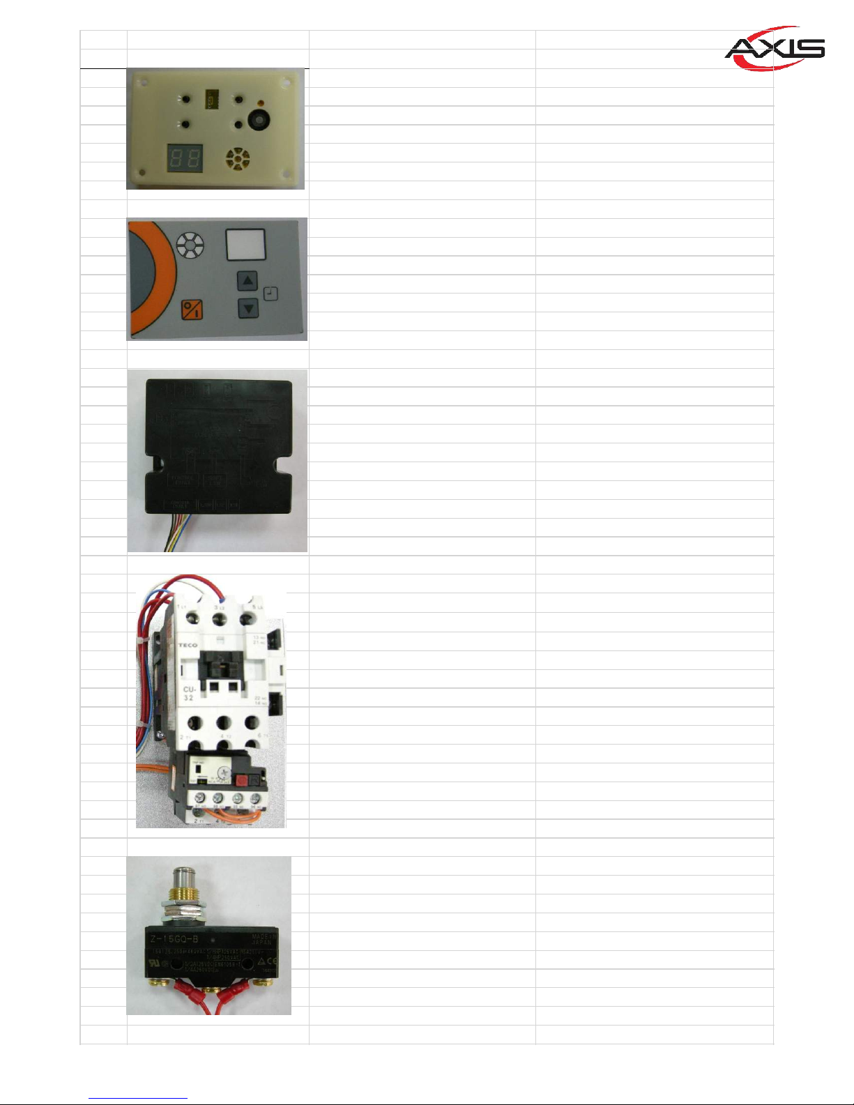
NO. PI CTURE PARTS NUMBER PARTS NAME
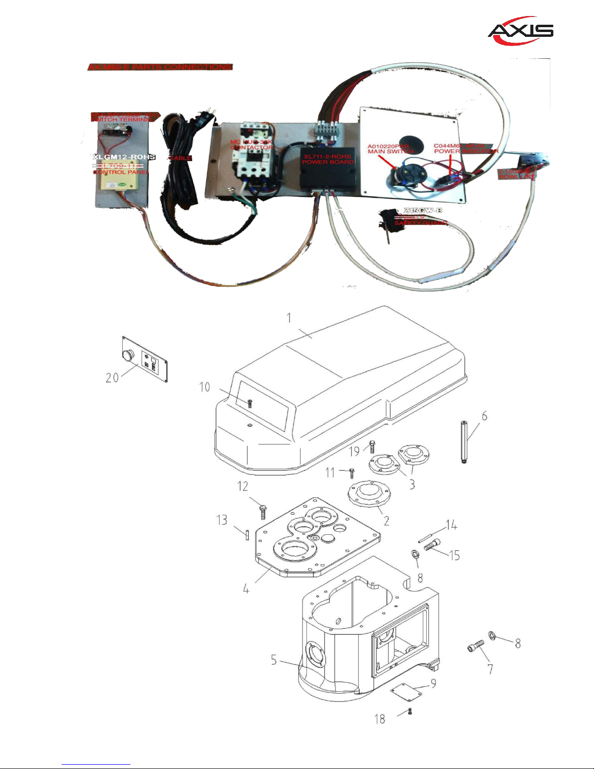
1 XL709-11A CONTROL PANEL W/BOX
2 D11001R STICKER OF PANEL
3 XL711-2-ROHS Power Board W/ BOX
4
MC HUO-11AK/2HP CONTACTOR-220V-3 PHASE
5 Z-15GQ-B LIMIT SWITCH FOR GUARD
9
Page 10
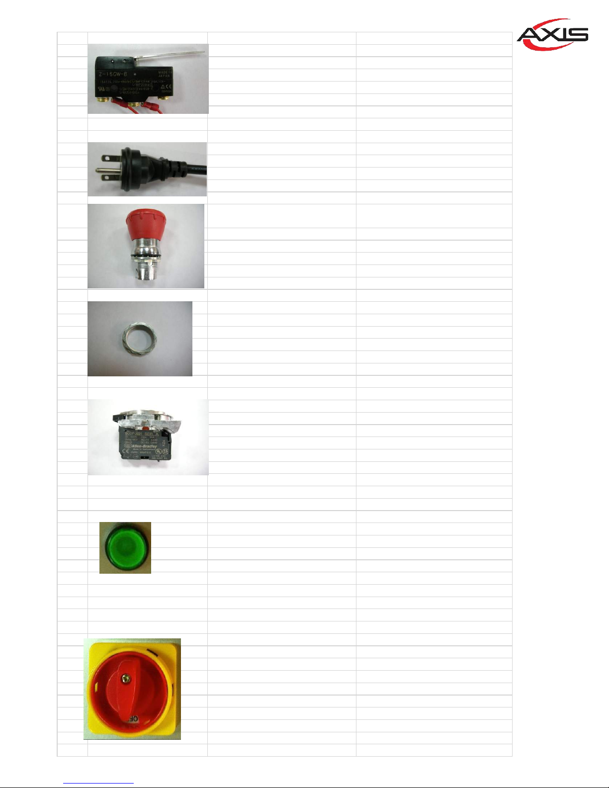
6 Z-15GW-B LIMIT SWITCH FOR BOWL LIFT
10
7
8
9
CABLE-12-3C-NEMA6-15P-UL POWER CABLE W/PLUG
EMERGENCY STOP (RED
ABESMT44
ABMS800M
ABAU8F01
BUTTON)
LOCK NUT
SWITCH TERMINAL
(800F-X01)
11
12
10
C044M6L-AS-02 POWER INDICATOR
A010220PSR MAIN SWITCH
Page 11
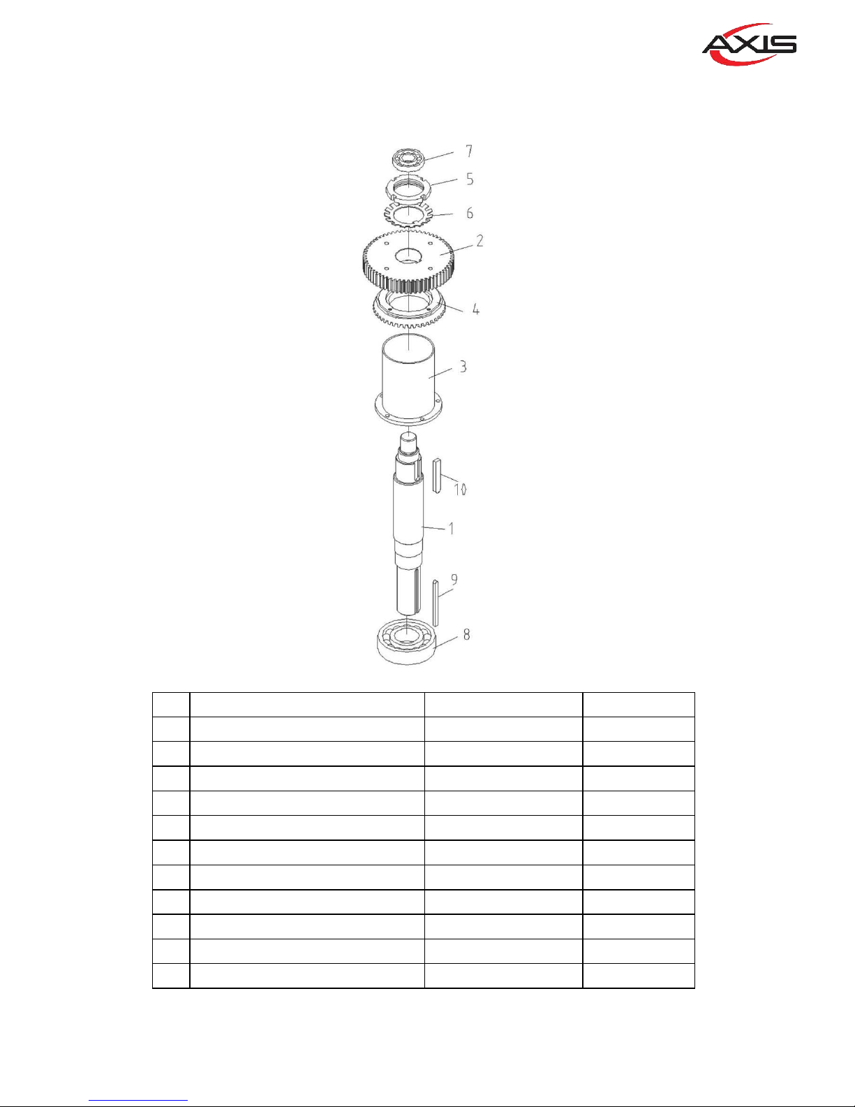
Description or Name Part No. Qty
1
AGITATING SHAFT
11100B-02-001B 1
2
GEAR(50T)
11100B-02-003 1
3
Resistance oil casing
11100B-02-004 1
4
Bevel gear
11193-02-006 1
4
WASHER
11193-02-006A 1
5
LOCK WASHER
M55 1
6
LOCK NUT
MN55 1
7
BALL BEARING 6207Z
BR-6207 1
8
BALL BEARING 6010Z
BR-6010 2
9
KEY
KR-1/4*1/4*100 1
10
KEY
KR-09*14*52 1
02
11
Page 12
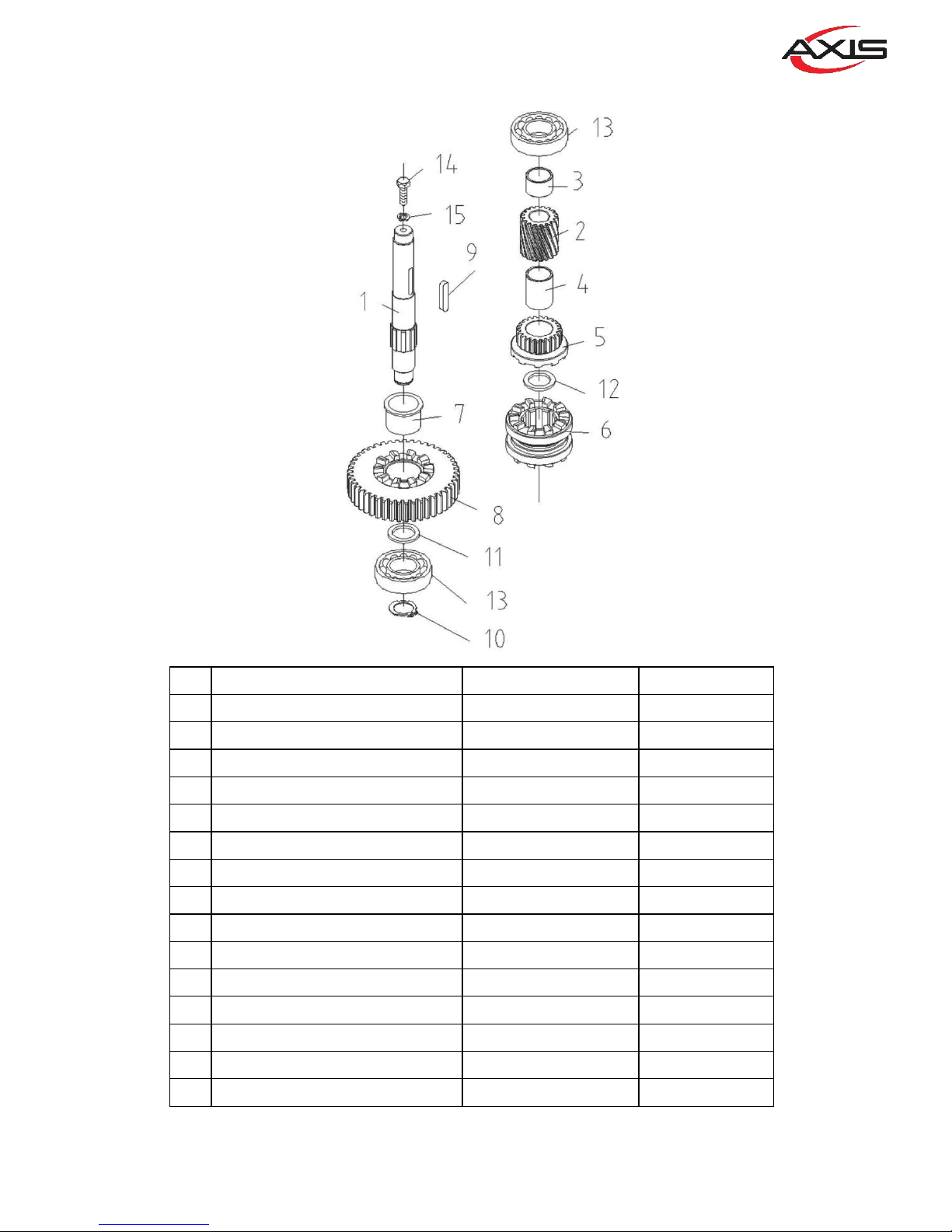
Description or Name Part No. Qty
1
GEAR SHAFT
11100B-03-001 1
2
GEAR(16T)
11100B-03-002 1
3
WASHER
11100B-03-003 1
4
CLUTCH COPPER BUSHING
11100B-03-004 1
5
GEAR(19T)
11100B-03-005 1
6
SHIFTING CLUTCH
11091-03-002 1
7
CLUTCH COPPER BUSHING
11100B-03-007 1
8
GEAR(32T)
11100B-03-008 1
9
KEY
KRR-08*08*43 1
10
C- TYPE SNAP RING S25
STW-S25 1
11
WASHER
1100B-03-011 1
12
WASHER
11100B-03-012 1
13
BALL BEARING 6205
BR-6205 1
14
BOLT 3/8*1/2
S-3/8*1/2 1
15
SPRING WASHER
SW3/8 1
03
12
Page 13
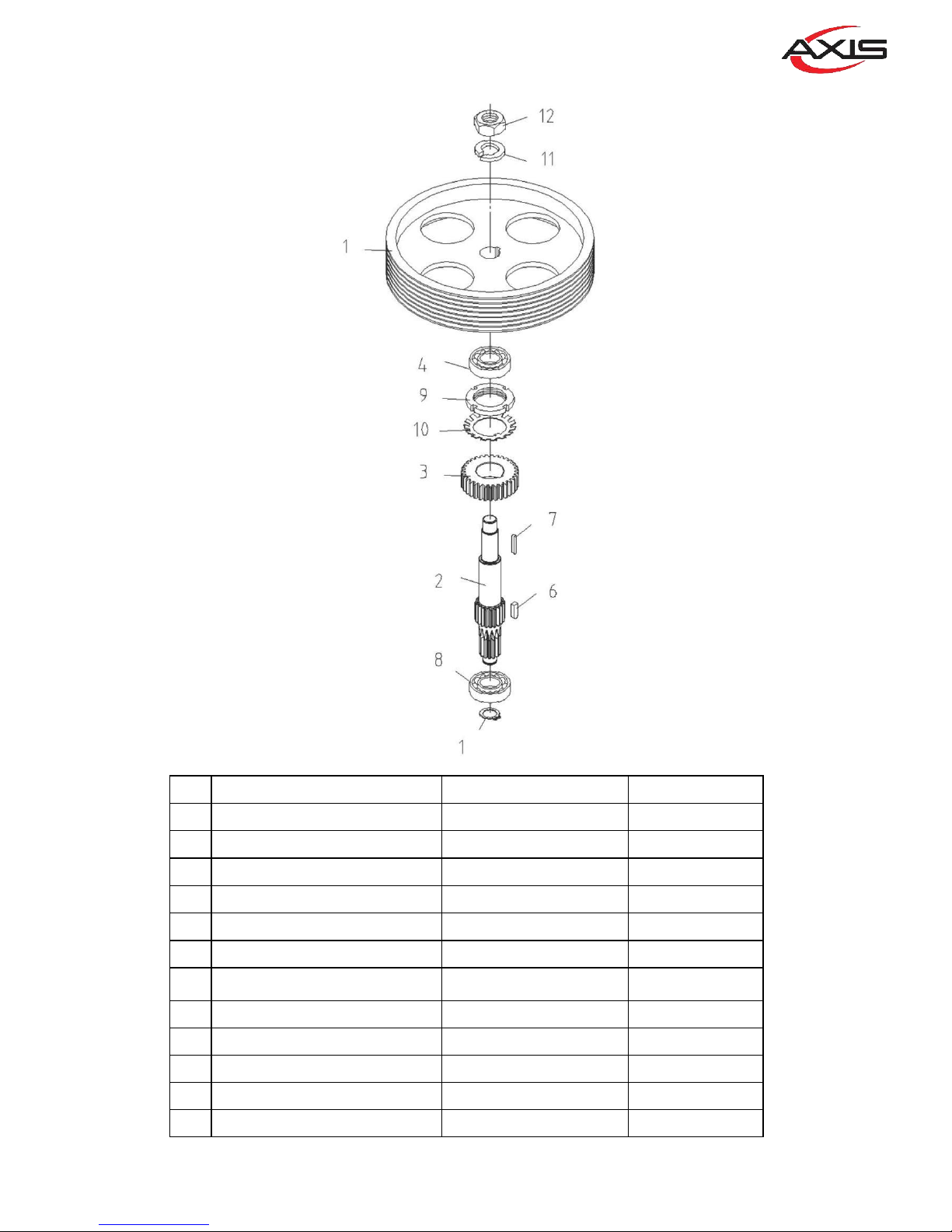
Description or Name Part No. Qty
1
PULLEY
11092-03-001 1
2
GEAR SHAFT
11100B-04-001 1
3
GEAR(22T)
11100B-04-004 1
4
BALL BEARING 6206
BR-6206 1
5
C- TYPE SNAP RING S25
STW-S25 1
6
KEY 1/4*1/4*50
KR-1/4*1/4*50 1
7
KEY
KRR-10*08*28 1
8
BALL BEARING 6205
BR-6205 1
9
LOCK WASHER
M40*1.5P 1
10
LOCK NUT
MN40 1
11
SPRING WASHER
SW-1/2 1
12
NUT
W1*12NF 1
04
13
Page 14
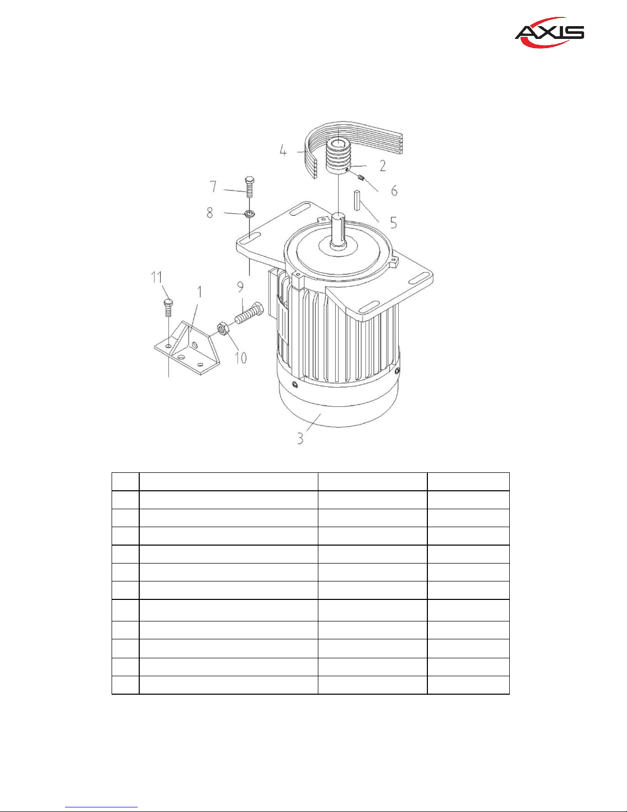
Description or Name Part No. Qty
1 Motor Fixed Seat 11092-05-006 1
2
MOTOR PULLEY
11092-05-003 1
3
MOTOR
11092-05-005 1
4
BELT
M7*1320 8
5
KEY 7*7*40
KR-7*7*40 1
6
SET SCREW 1/4*5/8
S-S1/4*5/16 1
7
BOLT 3/8*3/4
S-3/8*3/4 4
8
WASHER 3/8"
W-3/8 4
9
BOLT 1/2*4
S-1/2*4 1
10
NUT
NUT-W1/2"*12NC 1
11
BOLT 3/8*3/4
S-3/8*3/4 2
05
14
Page 15
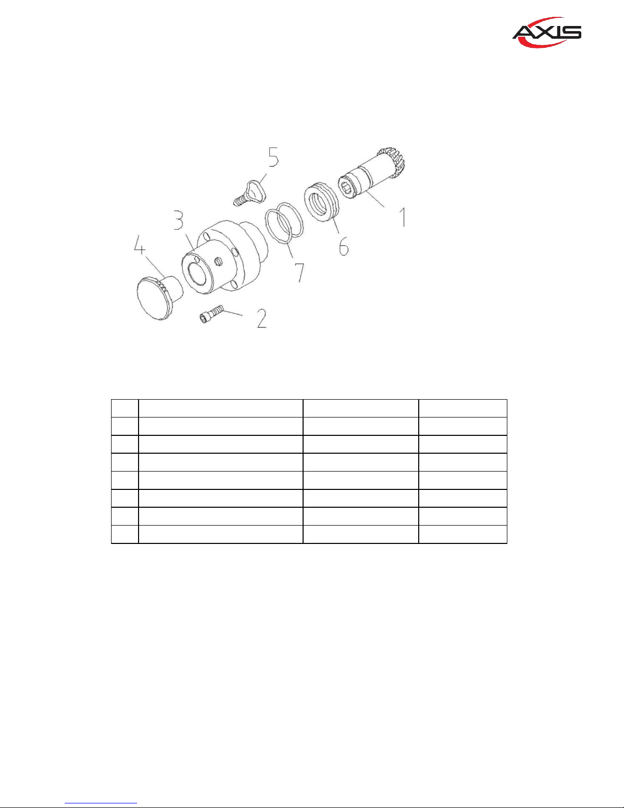
Description or Name Part No. Qty
1
GEAR (14T)
11093-06-001 1
2
CAP SCREW 5/16*1- 1/4
S-C-5/16*1-1/4 4
3
HUB ATTACHMENT
11093-06-002 1
4
ATTACHMENT HOLE PLUG
11091-06-004 1
5
THUMB SCREW
11031-06-005 1
6
BALL BEARING 2907
BR-2907 1
7 O SNAP RING P35 OR-P35 2
06
15
Page 16
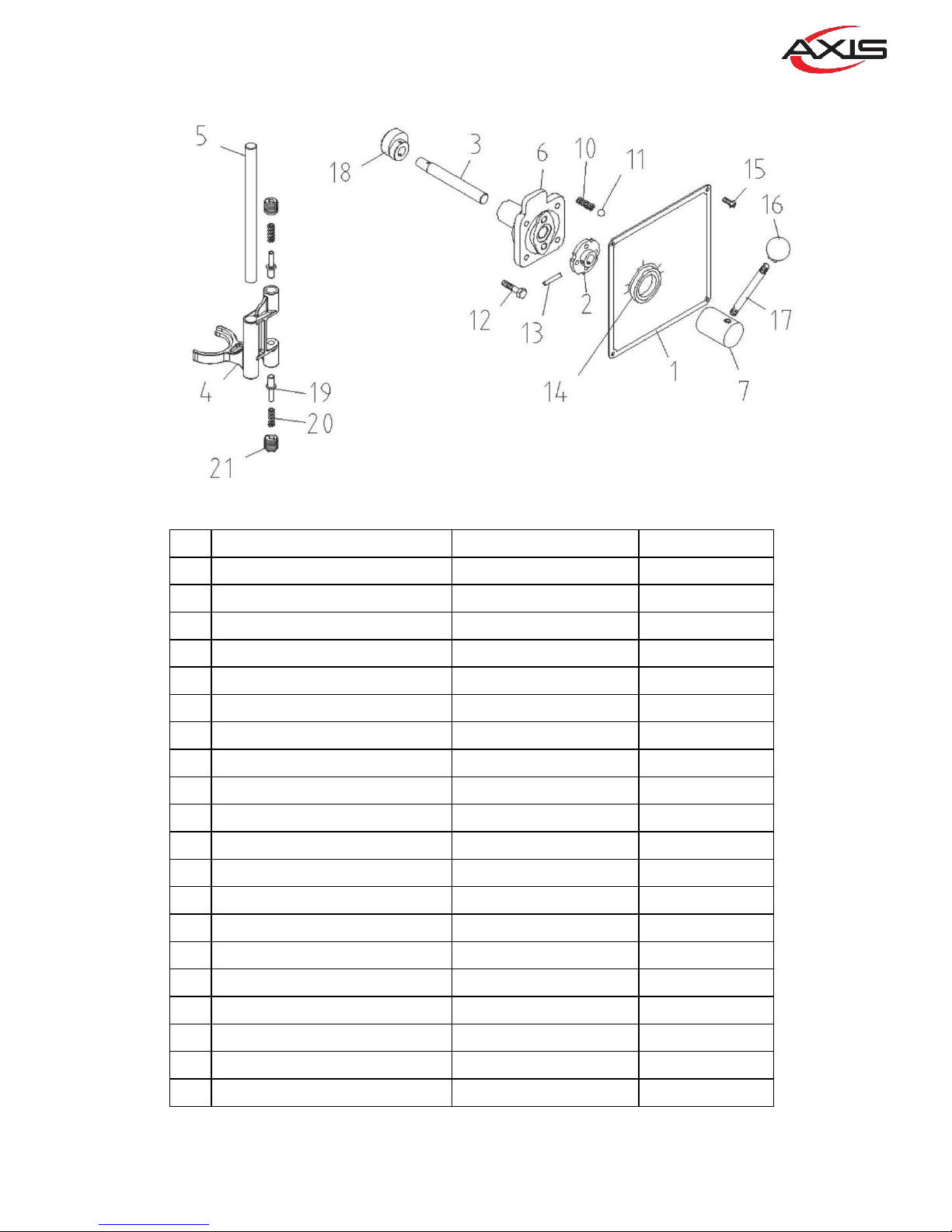
Description or Name Part No. Qty
1
CONTROL PANEL
1109S-01-006D 1
2
HUB & CAM ASSY.
1109S-07-013B 1
3
ECCENTRIC SHIFT SHAFT
1109S-07-003B 1
4
SHAFT FORK
11091S-07-004B 1
5
SHIFTER FIXED SHAFT
11091S-07-005B 1
6
BRACKET GEAR SHIFT
11091-07-006 1
7
HANDLE SEAT
11092-07-007 1
8
NUT 1/2*12NC
NUT-1/2*12NC 1
10
COMPRESSION SPRING
11091-07-018 2
11
STEEL BALL 6
SB-6 2
12
SCREW
S-C5/16*5/8 4
13
SPRING PIN 5*28
SPP-5*28 1
14
OIL SEAL TC38*50*07
OS-TC38*50*07 1
15
MACH SCREW 3/16*3/8
S+R3/16*3/8 4
16
SHIFT HANDLE KNOB
11091-07-012 1
17
SHIFT HANDLE
11091-07-001 1
18
SHIFTING CAM
11091S-07-008B 1
19
PLUNGER
11091S-07-009B 1
20
COMPRESSION SPRING
11091-07-010 2
21
SET SCREW
11091-07-011 2
07
16
Page 17
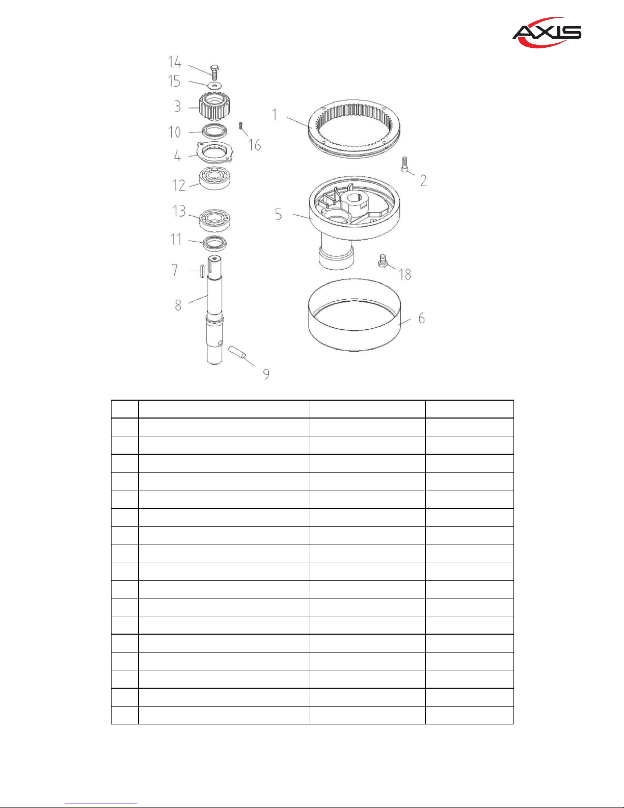
Description or Name Part No. Qty
1 INTERNAL DRIVE GEAR(59T) 11091-08-001 1
2
CAP SCREW 3/8*1- 1/4
S-C-3/8*1-1/4 4
3 INTERNAL PINION (18T) 11091-08-003 1
4
RETAINER
11091-08-004 1
5
PLANETARY HEAD
11091-08-005 1
6
HEAD RING
11091-08-006 1
7
KEY 6*6*35
KR-6*6*35 1
8
AGITATING SHAFT
11091-08-008 1
9
TAPERED PIN
11091-08-009 1
10
OIL SEAL TC43*58*08
OS-TC43*58*08 1
11
OIL SEAL TC40*72*10
OS-TC40*72*10 1
12
BALL BEARING 6306Z
BR-6306Z 1
13
BALL BEARING 6207Z
BR-6207Z 1
14
CAP SCREW 3/8*1
S-C-3/8*1 1
15
WASHER 3/8"
WB-3/8 1
16
MACH SCREW 1/4*5/8
S+R1/4*5/8 2
18
BOLT 1/2*3/4
S-1/2*3/4 1
08
17
Page 18
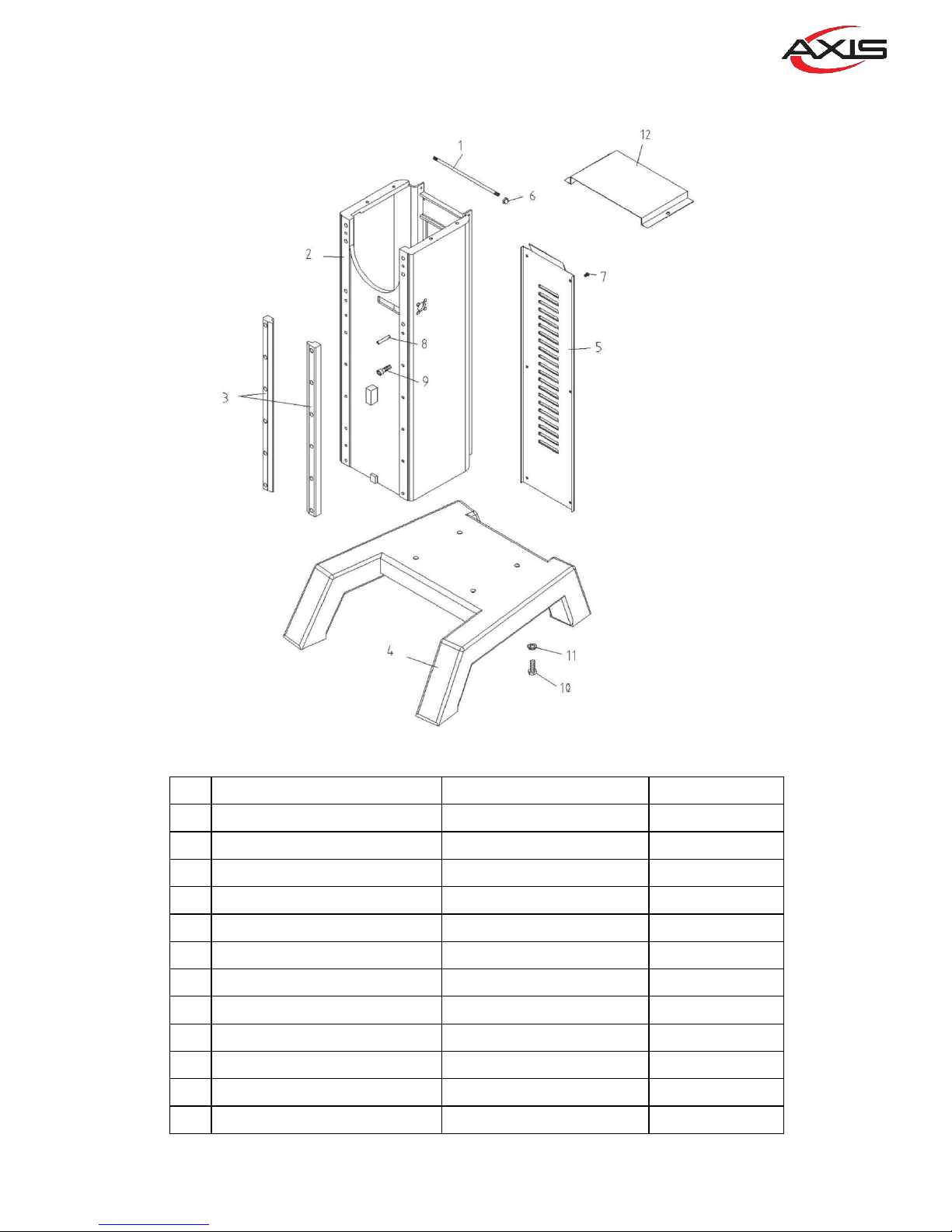
Description or Name Part No. Qty
1
HINGE SCREW
11091-09-001 1
2
COLUMN
BM60-09-002 1
3
SLIDEWAY
11091-09-003 2
4
BASE
11091S-09-004C 1
5
COLUMN COVER
11091-09-005 1
6
NUT 5/16*18NC
NUT-5/16*18NC 2
7
BOLT 1/4*3/8
S-1/4*3/8 8
8
SPRING PIN 8*50
SPP-8*50 4
9
CAP SCREW 3/8*1- 1/2
S-C-3/8*1-1/2 12
10
BOLT 5/8*3
S-5/8*3 4
11
SPRING WASHER 5/8"
SW-5/8 4
12
APRON
AXM60-09-016 1
09
18
Page 19

Description or Name Part No. Qty
1
BOWL CLAMP(LEFT)
11091-10-001A 2
1
BOWL CLAMP(RIGHT)
11091-10-001B 2
2
NUT 5/8*11NC
NUT-5/8*11NC 4
3
BOWL SUPPORT
11091-10-003 1
4
BOWL RETAINER
11091-10-004 1
5
BOWL LOCATING PIN
11091-10-005 2
6
APRON
11091-10-006 1
7
MACH SCREW 3/16*1/4
S+R3/16*1/4 4
8
CAP SCREW 1/4*3/4
S-C-1/4*3/4 2
9
NUT 1/2*12NC
NUT-1/2*12NC 2
10
SPRING WASHER 1/2"
SW-1/2 2
10
19
Page 20
11
20
Page 21
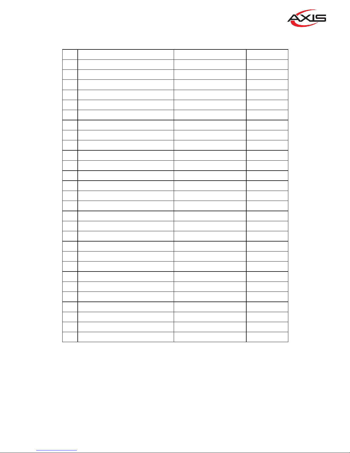
Description or Name Part No. Qty
1
WHEEL HANDLE
11091-11-001 1
2
LIFTING WHEEL
11091-11-002 1
3
CLAMPING ARM
11091-11-003 1
4
WHEEL HANDLE
11091-11-004 1
5
WHEEL BRACKET
11091-11-005 1
6 LIFTING GEAR (41T) 11091-11-006 1
7
LIFTING SCREW
BM60-11-007 1
8
LIFTING NUT
11091-11-008 1
9
RETAINER
11091-11-009 1
10 GEAR (31T) 11091-11-010 1
11 BEVEL GEAR (23T) LIFTING 11091-11-011 1
12
SHAFT
11091-11-012 1
13 BEVEL GEAR (23T) WHEEL 11091-11-013 1
14
CAP SCREW 5/16*1- 1/2
S-C-5/16*1-1/2 4
15
TAPERED PIN 4*32
TP-4*32 2
16
C- TYPE SNAP RING S19
STW-S19 1
17
KEY 5*5*15
KR-5*5*15 1
18
OIL CUP ( 五) OIL-BELL-1/8*3/4
1
19
NUT 1/2*12NC
NUT-1/2*12NC 1
20
KEY 5*5*10
KRR-5*5*10 1
21
FLAT WASHER
WB-3/4 1
22
KEY 5*5*13
KRR-5*5*13 1
23
BALL BEARING 2903
BR-2903 1
24
BALL BEARING 6203
BR-6203 1
25
LOCK WASHER 17
M17 1
26
LOCK NUT
MN17 1
27
SPRING WASHER 3/8"
SW-3/8 2
28
BOLT 3/8*1
S-3/8*1 2
21
Page 22
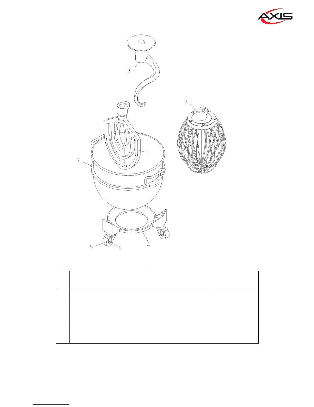
Description or Name Part No. Qty
1
BEATER
11091-12-001 1
2
SS WHIP
11091-12-002 1
3
HOOK
11091-12-003 1
4
TROLLEY BASE
11091-12-011 1
5
WHEEL 2.5"
WHEEL-001 3
6
NUT 1/2*12NC
NUT-1/2*12NC 3
7
BOWL
11091-12-008 1
12
22
Page 23
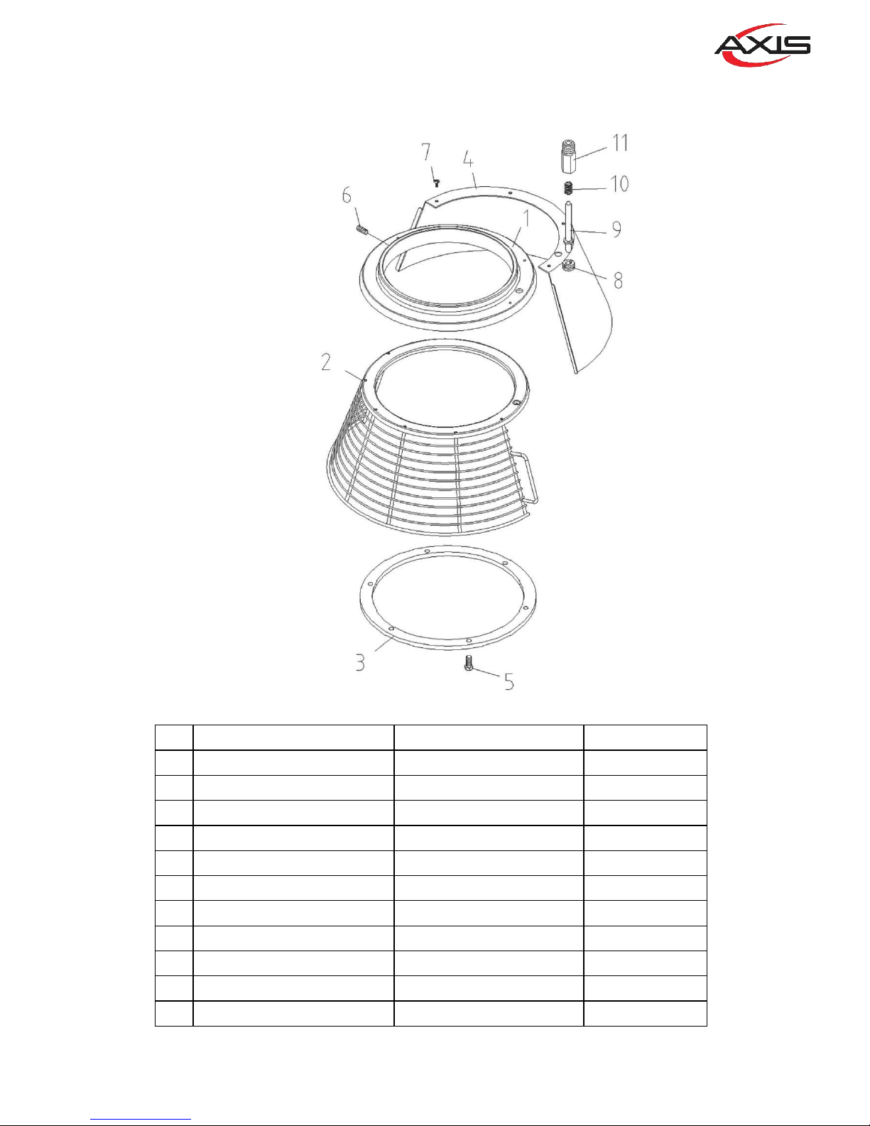
Description or Name Part No. Qty
1
BACK COVER
GM60-13-001A
1 只
2
FRONT COVER (WIRE)
GM60-13-002B
1 只
3
FIXED RING
11091-13-003A
1 只
4
FIXED SHEET
11091-13-004
1 只
5
BOLT 3/16*1/2
S-3/16*1/2
6 支
6
SET SCREW 5/16*3/8
S-S5/16*3/8
3 只
7
SCREW
S+BR-3/16*1/4
4 支
8
SCREW
1109P-13-008
1 只
9
CONTROL SHAFT
11091-13-007
1 只
10
COMPRESSING SPRING
11091-13-012
1 只
11
CONTROL SHAFT SEAT
1109P-13-006
1 只
13
23
Page 24

24
 Loading...