

MV Heating MV Airo 4 Instruction Manual
+44 (0)23 8052 2345
1
MV Heating UK Ltd
MV Airo 4
MV Airo 4
Diesel Powered
Air Heater
Instruction Manual
Ed. 2.01
MV Heating UK Ltd
Unit 6
Second Avenue Business Park
Millbrook
Southampton
SO15 0LP

+44 (0)23 8052 2345
2
MV Heating UK Ltd
Preface
Thank you for purchasing the MV Airo 4 diesel heater (hereinafter referred to
as ‘the heater’). This manual will attempt to describe the structure, working
principle, installation and operation of the heater. For future reference please
keep this manual in a safe and convenient place.
Note
• This instruction booklet is subject to revision without notice but the
instruction book is in conformity to the purchased product.
• The manual will attempt to answer any and all questions the user
may have. If you have and further questions or find anything
incorrect within this manual, please contact us directly.
• Please check that the heater is not damaged when first unpacking it
and contact the dealer immediately if any problems are found.
• If any problems or faults arise during installation or operation, please
contact us directly or any other customer service station authorised
by our company. We shall do our best to offer you our full support.

+44 (0)23 8052 2345
3
MV Heating UK Ltd
Contents
Uses and Applications ................................................................................................................... 5
Safety Information ................................................................................................................... 6
Technical Data .............................................................................................................................. 7
Kit Contents ............................................................................................................................. 8
MV Airo 4 Dimensions ............................................................................................................. 9
Installation: ................................................................................................................................. 10
Installation Positions .............................................................................................................. 10
Installation Angle ................................................................................................................... 12
Wiring Harness Connector Positions ................................................................................. 13
Installation: Mounting ........................................................................................................... 14
Installation: Ducting and Pipework ........................................................................................ 16
Exhaust System ................................................................................................................. 17
Combustion Air Intake ...................................................................................................... 18
Installation: Fuel Lines ........................................................................................................... 19
Fuel Line Connectors ......................................................................................................... 20
Fuel Line Length and Order ............................................................................................... 21
Fuel Pump Angle for Installation ....................................................................................... 22
Fuel Tank Head ................................................................................................................. 23
Fuel Standpipe .................................................................................................................. 24
Electrics: ..................................................................................................................................... 26
Components .......................................................................................................................... 26
Wiring Diagram ...................................................................................................................... 27
Control Connections .............................................................................................................. 28
Operation: .................................................................................................................................. 30
Rheostat Control .................................................................................................................... 30

+44 (0)23 8052 2345
4
MV Heating UK Ltd
Mini Timer ............................................................................................................................. 30
Manual Start Up and Shut Down ...................................................................................... 32
Pre-setting Heating Time .................................................................................................. 32
Pre-setting Starting and Heating Times ............................................................................ 32
Checking Temperature ...................................................................................................... 33
Converting to Thermostatic Mode .................................................................................... 33
Fault Information .............................................................................................................. 33
Remote Operation ............................................................................................................ 34
Installation Fuel Priming Feature ...................................................................................... 34
LCD Digital 7-Day Timer ......................................................................................................... 35
Changing Language ........................................................................................................... 36
Changing the Date and Time ............................................................................................. 37
Manual On/Off .................................................................................................................. 38
Switching to Thermostatic Mode ...................................................................................... 39
Fan Mode .......................................................................................................................... 39
Pre-setting Heating Times ................................................................................................. 40
Installation Fuel Priming Feature ...................................................................................... 42
Checking Error Codes ........................................................................................................ 43
Resetting Digital Controller to Factory Settings ................................................................ 44
Maintenance............................................................................................................................... 45
Fault Codes: ................................................................................................................................ 46
Rheostat Control .................................................................................................................... 46
Timers .................................................................................................................................... 47

+44 (0)23 8052 2345
5
MV Heating UK Ltd
Uses and Applications
The heater works independently from the vehicle’s engine, but is best fitted
using the vehicle’s battery and fuel tank. An auxiliary battery and/or fuel tank
can be used if necessary.
The heater will operate under normal conditions in most vehicles from
industrial and machinery sectors to leisure craft like yachts and motor homes.
The heater is best uses for heating various cabins and compartments, engine
preheating and glass defrosting.
It is not recommended for constant long-term operation for residential
rooms, garages, holiday homes etc.
Note:
The most common faults that occur are generally down to poor fuel
conditions due to dirty (or empty) fuel tanks or drops in voltage; particularly
in older vehicles like live aboard narrowboats or used, commercial vehicles.

+44 (0)23 8052 2345
6
MV Heating UK Ltd
Safety Information
Follow the installation guidelines carefully to ensure the heater has the
appropriate amount of clearance between surfaces, so as not to become a
fire hazard and that the various parts of the heater that get hot, like the
exhaust, are not exposed or contaminated by possible fuel and oil.
Sufficient ventilation is required allowing proper air-flow to the heater. If the
heater is to be installed in a box or compartment, please ensure an air vent is
installed for this reason. The air must also be fresh and not contaminated by
exhaust fumes or other polluted sources. Make sure that the air intakes and
exhaust do not get blocked by other objects.
Take care to ensure that the exhaust outlet is installed in a way that prevents
fumes entering the vehicle or in the direction of the fresh air intake and
ensure the use of heat shields where necessary to again avoid fire damage.
If work is to be carried out on or around the heater, turn it off at least an hour
before so, so that it is sufficiently cool enough to be handled. If necessary,
wear safety gloves.
The fuel line must not be routed through the passenger compartment or the
driver’s cab in any vehicle. Ensure that they are also installed so that the exits
are not at risk or in danger of becoming a possible fire hazard.
Finally, take care and follow any and all precautions when installing the
heater to minimize injuries to yourself and damage to the heater.

+44 (0)23 8052 2345
7
MV Heating UK Ltd
Technical Data
Heat Power (W)
4000
Fuel
Diesel
Output (W)
900 - 4000
Fuel Consumption (l/h)
0.11 - 0.51
Run Time Power Consumption (w)
8 - 40
Working Temperature
-40°C - 20°C
Weight (kg)
4.5
Variable Output
Current Draw
Position
(Amps)
PO1
0.4
PO2
0.6
PO3
0.8
PO4
1.3
PO5
1.4
PO6
1.9
PO7
2.4
+44 (0)23 8052 2345
8
MV Heating UK Ltd
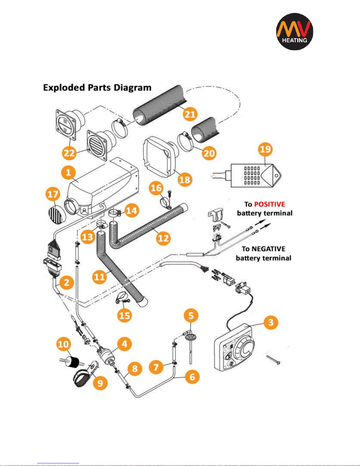
Kit Contents
The kit includes everything necessary for installation.
Figure I
+44 (0)23 8052 2345
9
MV Heating UK Ltd
1. Main heater unit 2. Main wiring harness
3. Control switch/timer 4. Fuel pump
5. Fuel standpipe 6. Fuel pipe
7. Fuel line connector hose clip 8. Fuel line connector
9. Fuel pump clamp 10. Anti-vibration mount
11. Combustion air pipe 12. Exhaust pipe
13. Combustion air pipe clamp 14. Exhaust pipe clamp
15. Combustion air pipe fixing clamp 16. Exhaust pipe fixing clamp
17. Grill 18. Outlet Cover
19. Temperature probe (optional) 20. Hose clip (optional)
21. Hot air ducting (optional) 22. Out vents (optional)
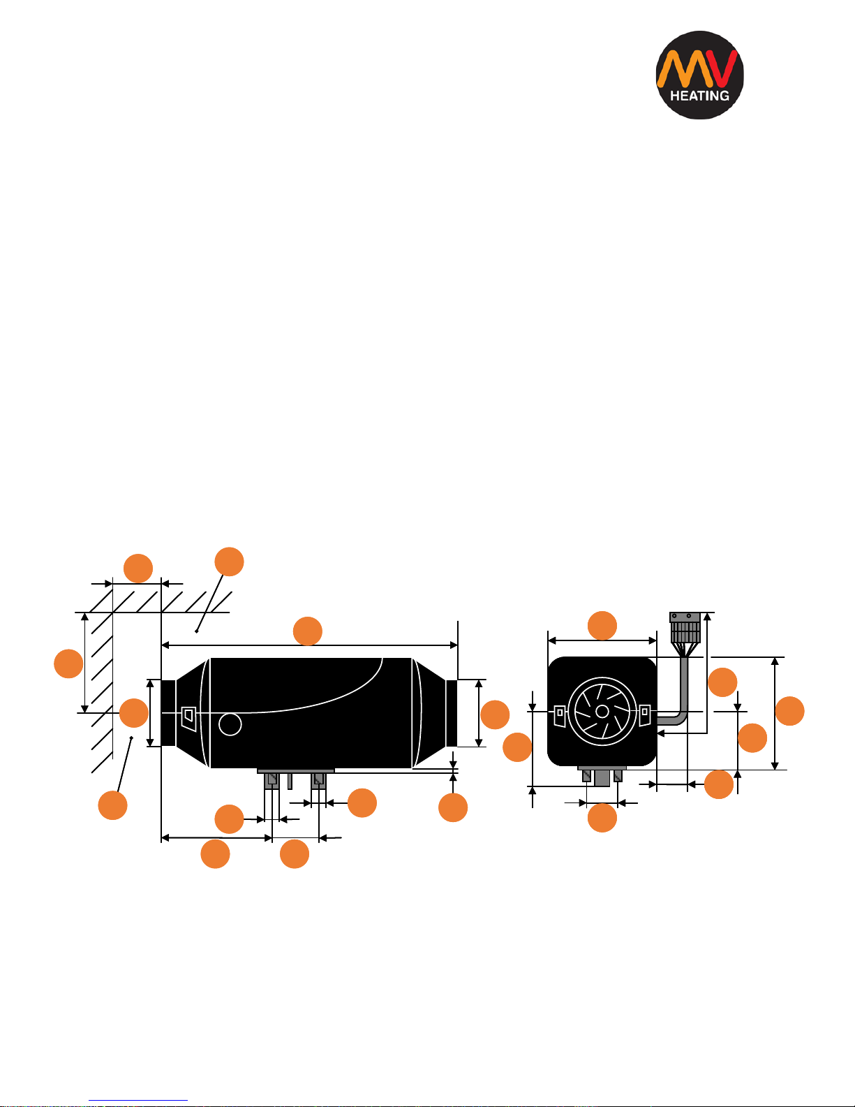
MV Airo 4 Dimensions
A: Minimum installation clearance for opening the lid and dismantling glow
pin and E.C.U.
B: Minimum installation clearance for the air intake
376
A
B
30
75
90
130
133
25
24
55
7
140
105
44
17
80
150
325
140
105
44
17
80
150
325
DIMENSIONS: mm
376
A
B
30
75
90
130
133
25
24
55
7
140
105
44
17
80
150
325
DIMENSIONS: mm
+44 (0)23 8052 2345
10
MV Heating UK Ltd
Installation:
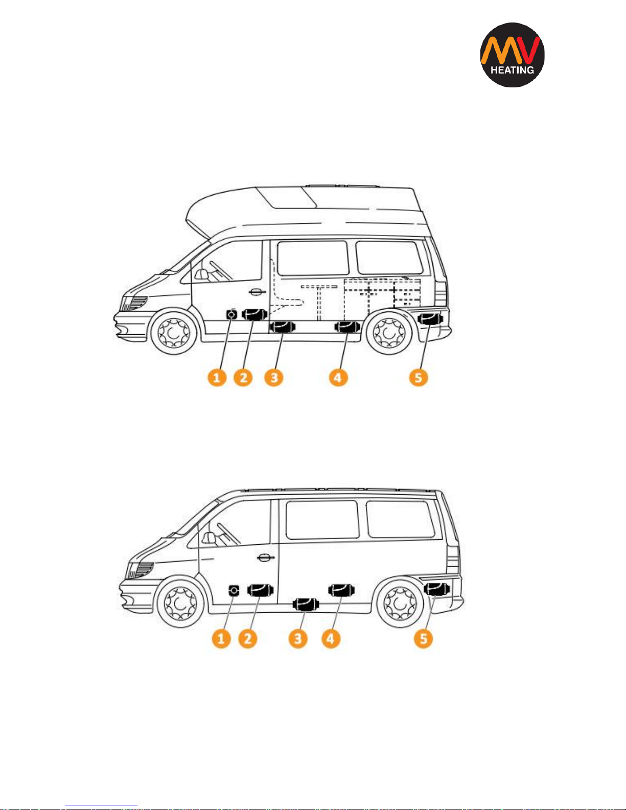
Installation Positions
Motorhome Figure II
1. In front of the passenger seat 2. Between the passenger and driver’s seat
3. Under the vehicle floor 4. Under the rear seat
5. Inside the boot
Minivan Figure III
1. In front of the passenger seat 2. Between the passenger and driver’s seat
3. Under the vehicle floor 4. Under the rear seat
5. Inside the boot
+44 (0)23 8052 2345
11
MV Heating UK Ltd
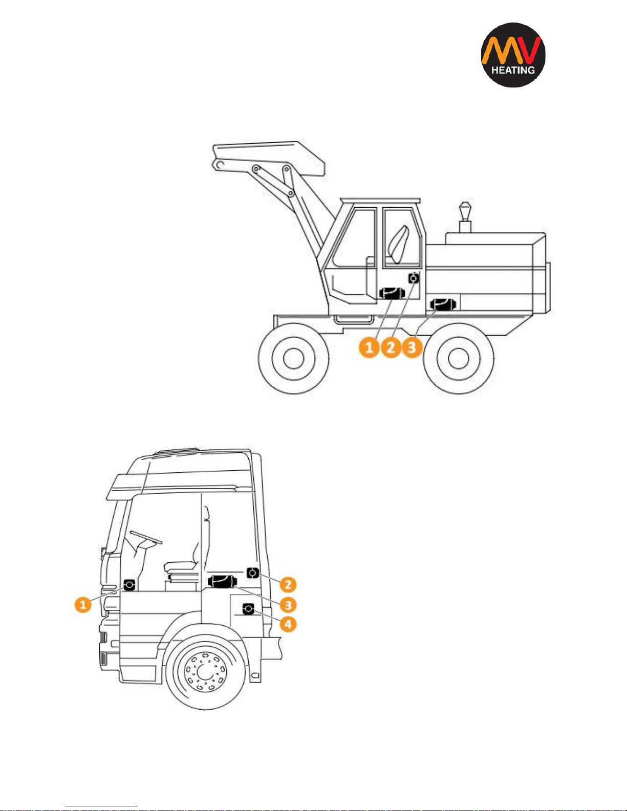
Crane Figure IV
1. In seat box
2. On the rear wall
3. In a protective
case
Lorry Figure V
1. In passenger footwell
2. On the cabin rear wall
3. Under the bed
4. In the tool box
+44 (0)23 8052 2345
12
MV Heating UK Ltd
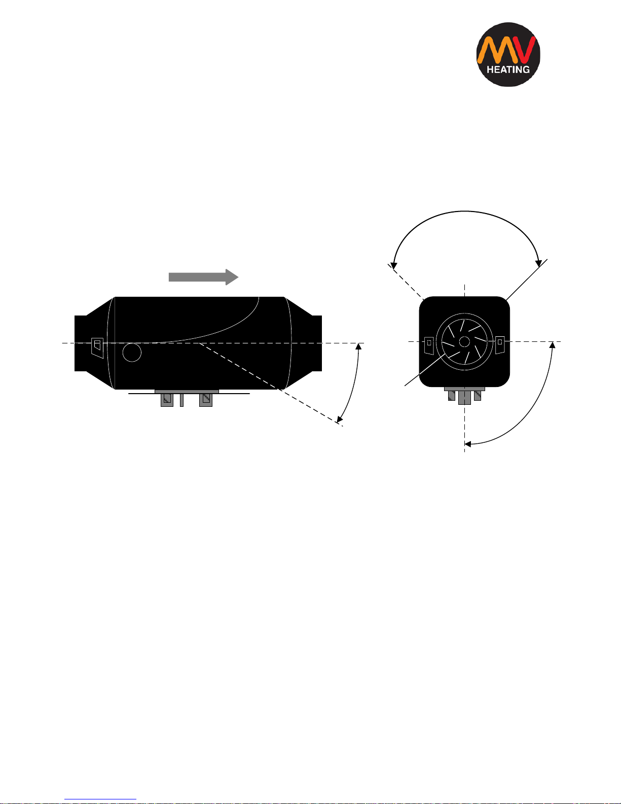
Installation Angle
All positions suggested are examples. Other locations are possible so long as
they correspond to the proper installation guidelines and requirements.
1. Heater air intake 2. Glow pin position 3. Direction of air flow
Figure VI
Figure VI shows the ideal installation position of the heater; with exhaust
pointing downward. Depending on its location it can be tilted by 30° with the
air flow and hot air outlet facing the bottom. It can also be tilted on its
longitudinal axis by 90° so long as the glow pin position points upward. During
usual operation the heater can deviate by 15° each way with vehicle
movement without impaired function of the heater.
1
30°
3
90°
2
1
+44 (0)23 8052 2345
13
MV Heating UK Ltd
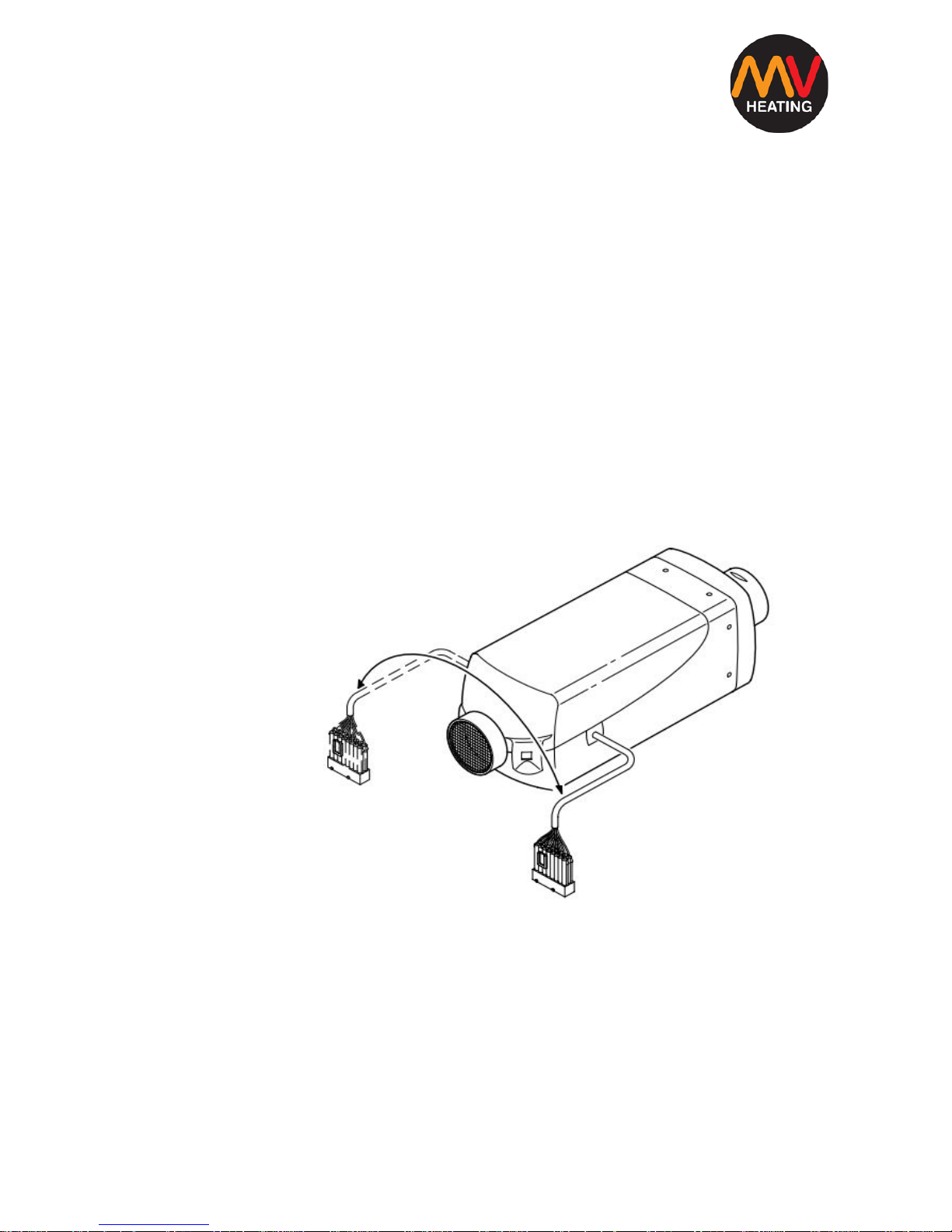
Wiring Harness Connector Positions
The main connector coming off the heater can be moved to the other side of
the heater if necessary. In order to do you must first remove the air inlet grill
by twisting it so it’s clear of its securing lip and then simply pull it off. Next,
remove the top cover by lifting up the two front flaps near the air inlet. You
can then lift out the entire innards of the heater (heat exchanger to fan motor
and all) removing the cable from the rubber securing bush and rerouting it
underneath the fan motor where it can then sit in the cut-out on the opposite
side. Ensure the rubber bush is properly inserted and the heat exchanger is
back securely in position, then simply replace the lid and grill back in position.
Note: Ensure the
bottom cover fits
correctly inside the
groove of the lid.
Figure VII
+44 (0)23 8052 2345
14
MV Heating UK Ltd
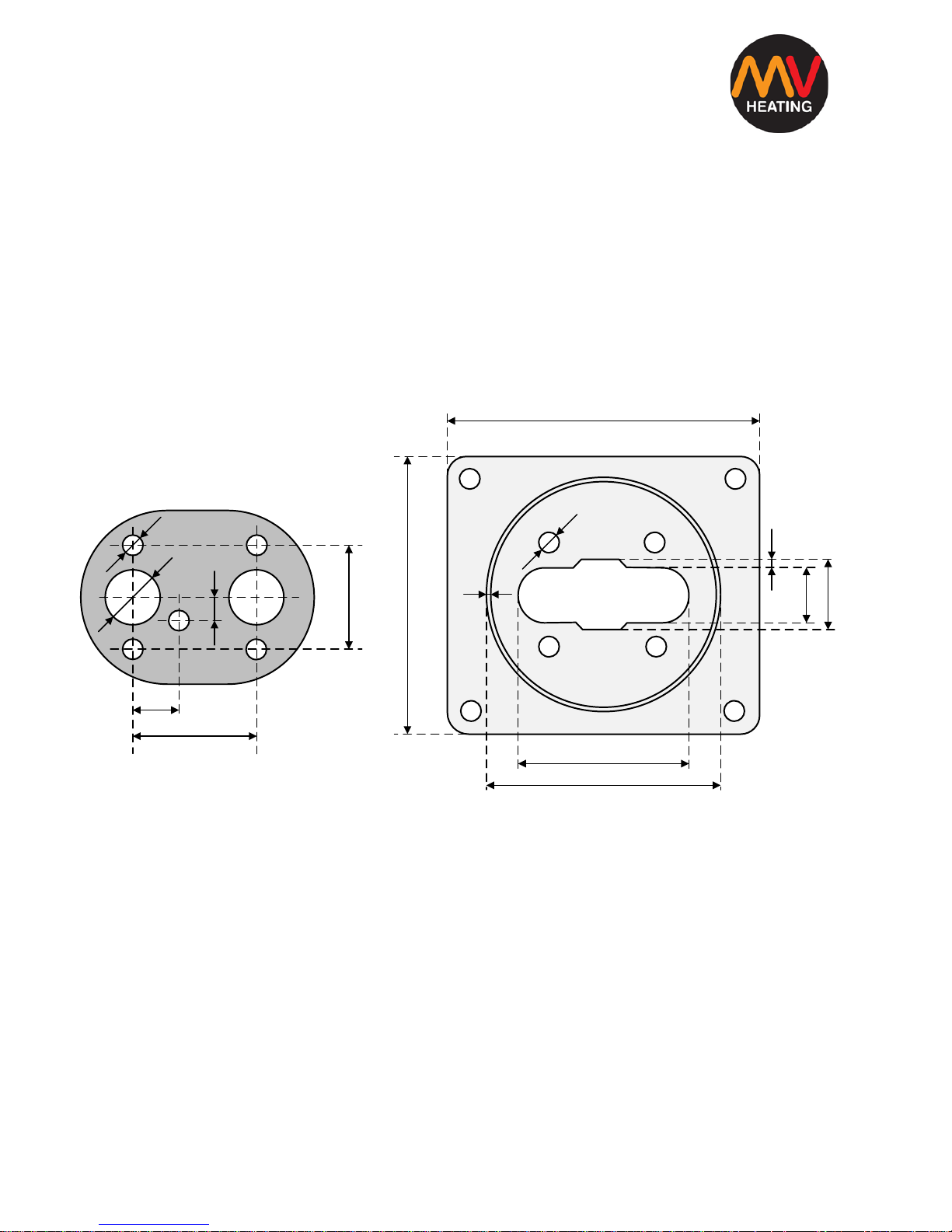
Installation: Mounting
The chosen mounting surface should be flat and you will need to drill the
appropriate size hole for the exhaust, combustion air inlet, fuel inlet and
mounting bolts. It is a good idea to mount the heater on the supplied
mounting bracket, particularly if the original mounting surface is thinner than
1.5mm.
A. Mounting Gasket B. Mounting Plate
Figure VII
Note: The mounting plate shown in figure VII may differ in overall size and
the circular flange may not be present, however the heater footprint will
remain the same.
148
7.5
170
85
125
2
5
25
35.5
7.5
26
12
44
18
55
DIMENSIONS: MM
A
B
+44 (0)23 8052 2345
15
MV Heating UK Ltd
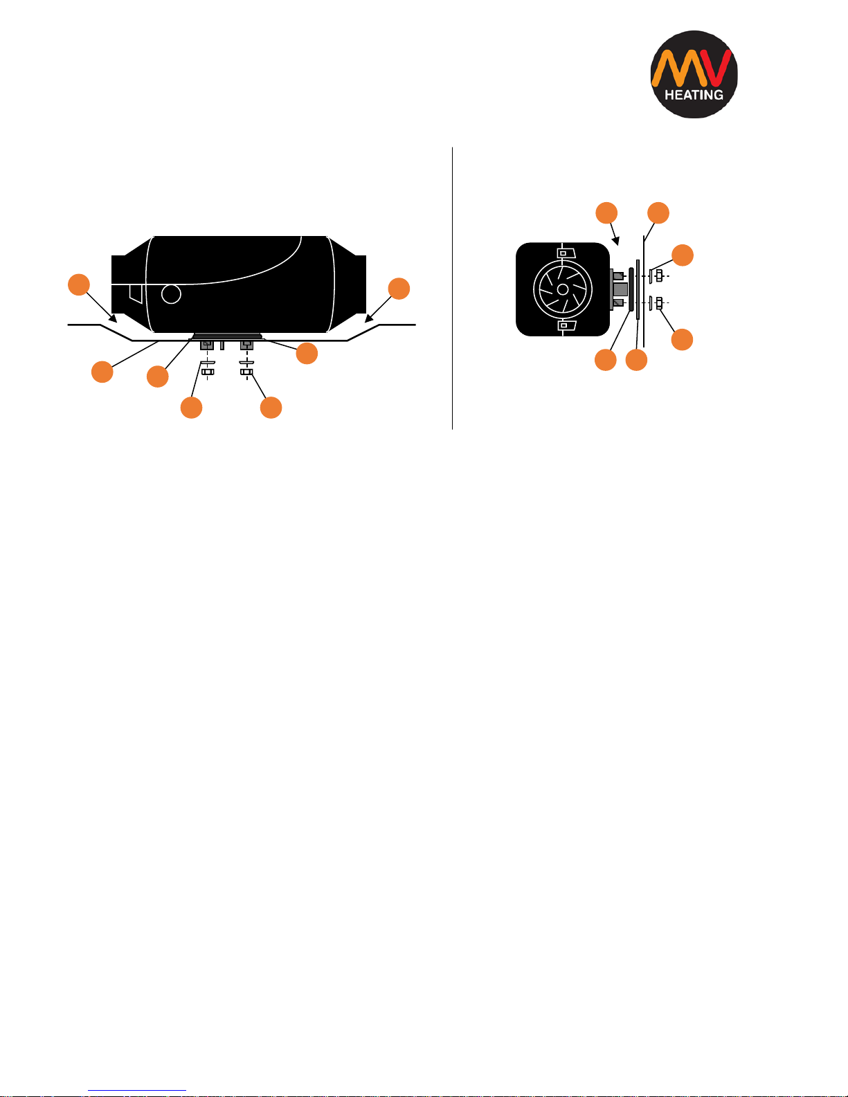
Installation: Mounting (Cont’d)
(Above) (Above)
Securing the heater to the floor Securing the heater to the wall
Figure VIII
1. Check that the fan wheel spins freely and 2. Ensure that the mounting surface is
that there is sufficient clearance between the flat and smooth
heater and the vehicle floor
3. The mounting gasket supplied must be fitted 4. The vehicle wall must be flat and
smooth
5. Mounting bracket 6. M6 Washer
7. M6 Nut
Figure VIII shows the mounting positions on a vehicle’s floor and wall.
1
4
6
5
3
2
1
43
6
5
21
 Loading...