

MV Heating MV Airo 2 Instruction Manual

+44 (0)23 8052 2345
1
MV Heating UK Ltd
MV Airo 2
MV Airo 2
Air Heater
Instruction Manual
Ed. 3.01
MV Heating UK Ltd
Unit 6
Second Avenue Business Park
Millbrook
Southampton
SO15 0LP

+44 (0)23 8052 2345
2
MV Heating UK Ltd
Preface
Thank you for purchasing the MV Airo 2 Air heater. This instruction book
describes the structures, working principles, installation and operation of the
MV Airo 2. For correct use of the heater, please read this instruction book
carefully before installation and use. The instruction book should be saved in
a convenient place for reference later.
Note
• This instruction book is subject to revision without notice, but the
instruction book is in conformity to the purchased product.
• Our effort is to explain all questions you may have. If you have any
doubts or find anything incorrect in this manual, please contact us
directly.
• Check the heater for any damage when unpacking and contact the
dealer immediately if anything is found.
• If any troubles arise during application, please contact MV Heating or
other customer service stations authorized by this company. We shall
do our best to provide service to you.
Comply with the operation manual for installation and use, to ensure
prolonged and reliable operation.

+44 (0)23 8052 2345
3
MV Heating UK Ltd
Contents
Introduction ....................................................................................................... 5
Technical Data .................................................................................................... 6
MV Airo 2 Internal Structure ...................................................................... 7
Structures and Working Principles ............................................................. 8
Case Assembly ............................................................................................ 9
Installation ....................................................................................................... 10
Installation of the Main Heater Body ....................................................... 12
Air Inlet & Outlet ...................................................................................... 14
Additional Ducting (Optional) .................................................................. 15
Installation of Combustion Air Pipe and Exhaust ..................................... 16
Fuel Lines...................................................................................................... 18
Fuel Standpipe ............................................................................................. 21
MV Airo2 Wiring Diagram – Brushless Version ............................................ 23
Timer and Rheostat Control Plugs ........................................................... 25
Wiring Loom Plug for Timer and Rotary Control ..................................... 26
Circuit Interfaces ...................................................................................... 27
Operation ......................................................................................................... 28
Rheostat Control .......................................................................................... 28
Mini Timer .................................................................................................... 29
Manual Start Up and Shut Down ............................................................. 30
Pre-setting Heating Time ......................................................................... 30

+44 (0)23 8052 2345
4
MV Heating UK Ltd
Pre-setting Starting and Heating Times ................................................... 30
Checking Temperature ............................................................................. 31
Converting to Thermostatic Mode ........................................................... 31
Fault Information ..................................................................................... 31
Remote Operation ................................................................................... 32
Installation Fuel Priming Feature ............................................................. 32
LCD Digital 7-Day Timer ............................................................................... 33
Changing Language .................................................................................. 34
Changing the Date and Time .................................................................... 35
Manual On/Off ......................................................................................... 36
Switching to Thermostatic Mode ............................................................. 37
Fan Mode ................................................................................................. 37
Pre-setting Heating Times ........................................................................ 38
Installation Fuel Priming Feature ............................................................. 40
Checking Error Codes ............................................................................... 41
Resetting Digital Controller to Factory Settings ....................................... 42
Maintenance .................................................................................................... 43
Fault Codes ....................................................................................................... 44
Rheostat Control .......................................................................................... 44
Fault Codes .......................................................... Error! Bookmark not defined.
Timers........................................................................................................... 45
+44 (0)23 8052 2345
5
MV Heating UK Ltd
Introduction
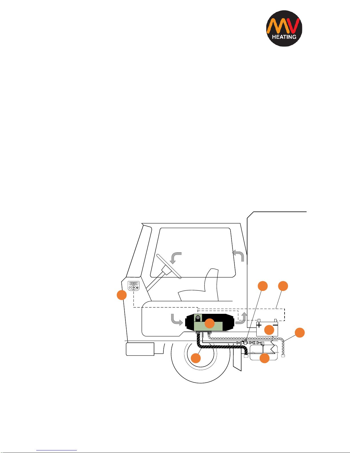
The main equipment of the MV Airo 2 air heater (hereinafter referred to as
‘the heater’) is a small fuel furnace controlled by a single-chip microprocessor. Its furnace body (the heat exchanger) is located in the hood
shaped case, which serves as an independent air passage. Cold air is drawn
into the air passage by the fan and blown out when it becomes hot.
The heat can be supplied by the heater to the driver’s cab and passenger’s
compartment independently from the engine. The schematic diagram is
shown in Fig I.
The heater is fully automatically controlled. It features a compact structure,
easy installation, low running costs, easy maintenance and is safe and
reliable.
1. Control switch
2. Heater Body
3. Fuel Pump
4. Wiring Harness
5. Vehicle’s Battery
6. Vehicle’s Fuel Tank
7. Exhaust Pipe
8. Combustion Air
Intake
Figure I
1
2
5
6
3 4
8
7

+44 (0)23 8052 2345
6
MV Heating UK Ltd
Technical Data
Output (w)
2000
Fuel
Petrol
Diesel
Voltage
12/24V
12/24V
Fuel Consumption (l/h)
0.14 - 0.27
0.12 - 0.24
Power Consumption
14 - 29
Working Temperature
-40°C - 20°C
Weight (KG)
2.6
Dimensions (mm)
323x120x121
Variable Output
Current Draw
Position
(Amps)
PO1
0.9
PO2
1.1
PO3
1.2
PO4
1.3
PO5
1.5
PO6
1.7
PO7
1.9
+44 (0)23 8052 2345
7
MV Heating UK Ltd
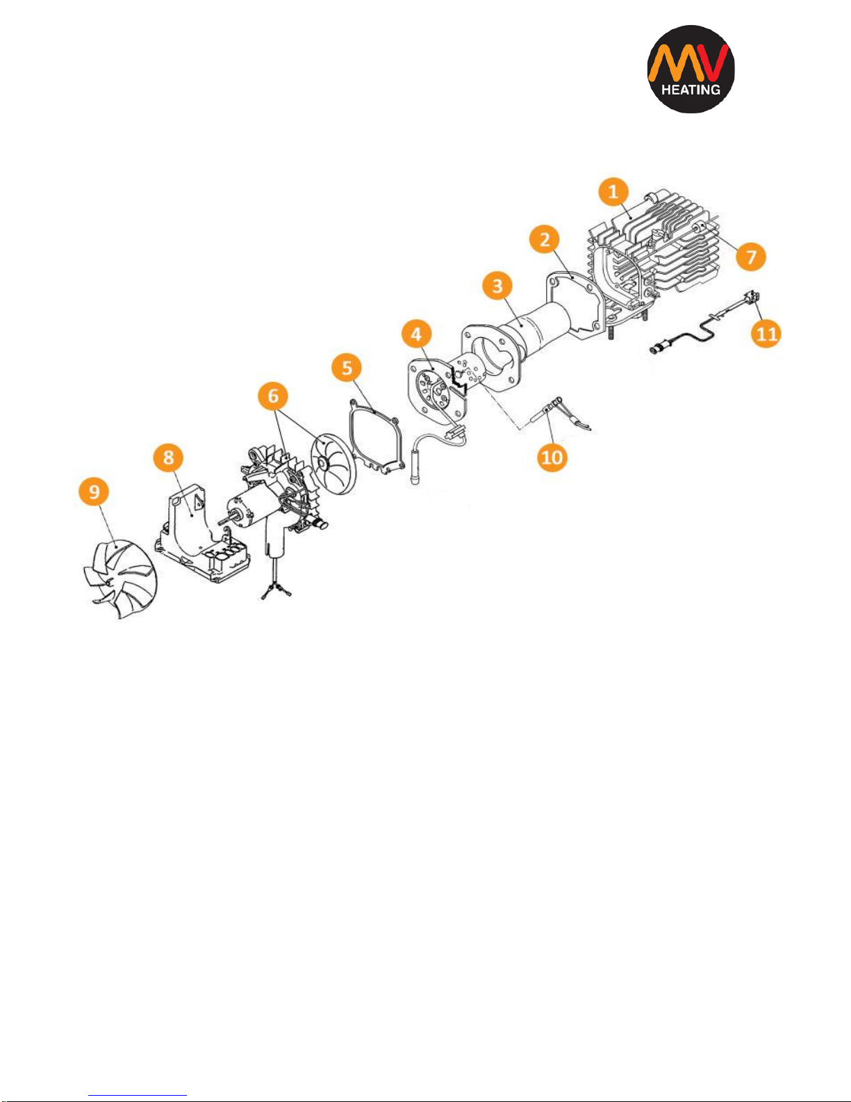
MV Airo 2 Internal Structure
Figure II
1. Heat exchanger 2. Gasket 1 (4 hole)
3. Combustion chamber 4. Burner Assembly
5. Gasket 2 (5 hole) 6. Air Motor Assembly
7. Insulating bush 8. ECU
9. Air Fan Wheel 10. Glow Pin
11. Overheat Sensor
+44 (0)23 8052 2345
8
MV Heating UK Ltd
The heat exchanger is made of die-cast aluminium, with radiating fins around
the rear. The combustion chamber fits inside the inner cavity of the heat
exchanger. The burner assembly and glow pin, fit into the end of the
combustion chamber. Fuel comes to the burner assembly through the fuel
pipe and is ignited by the glow pin. The flame is passed up the combustion
chamber and returns between the inner walls of the heat exchanger and
discharged through the exhaust outlet vent to the outside of the vehicle or
boat.
The air supporting combustion of the furnace, comes from the combustion air
inlet port and is sent down the combustion pipe by the combustion
supporting air blades of the fan motor.
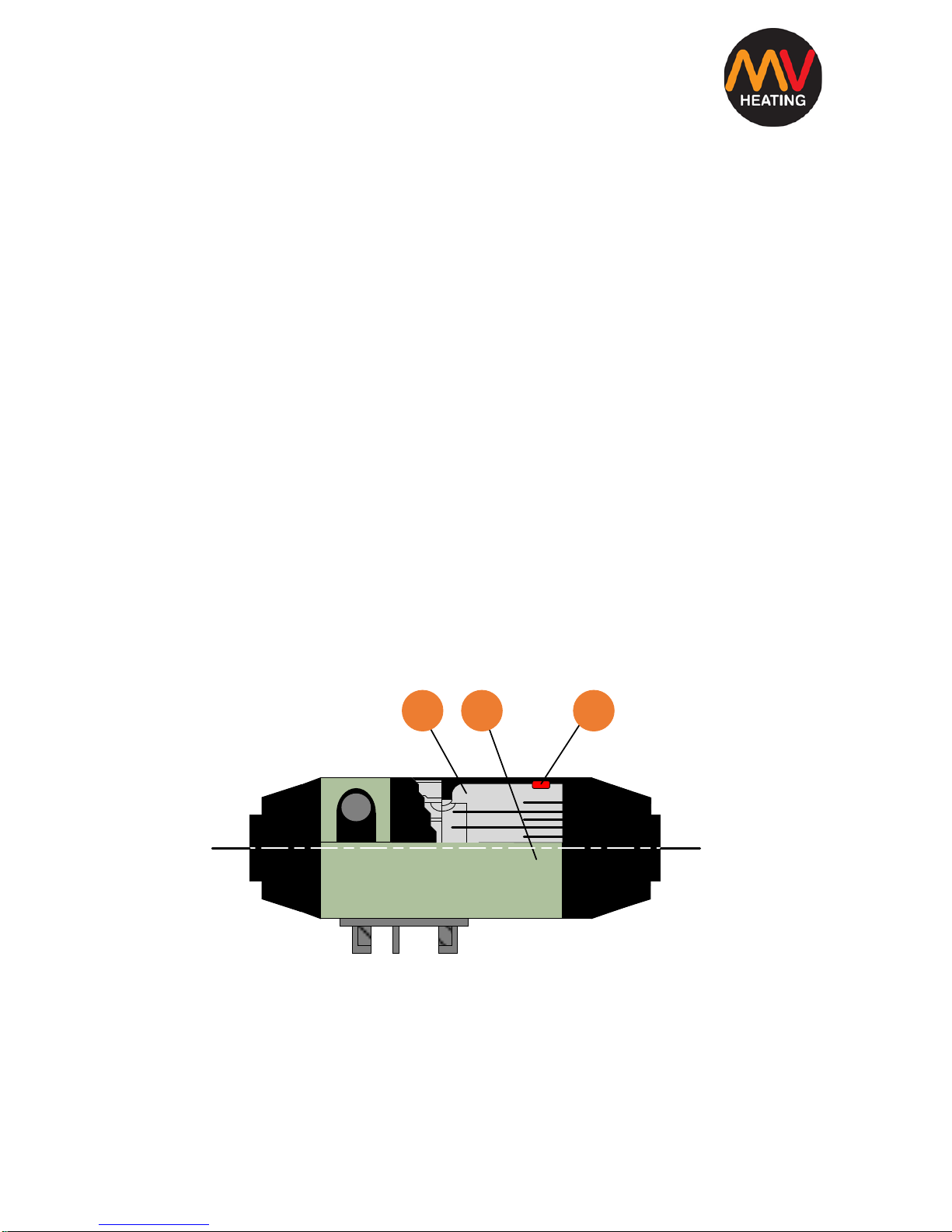
Structures and Working Principles
The structure of the main heater is shown in Fig. III
1. Heat Exchanger 2. Heater Case
3. Insulating Bush
Figure III
321
+44 (0)23 8052 2345
9
MV Heating UK Ltd
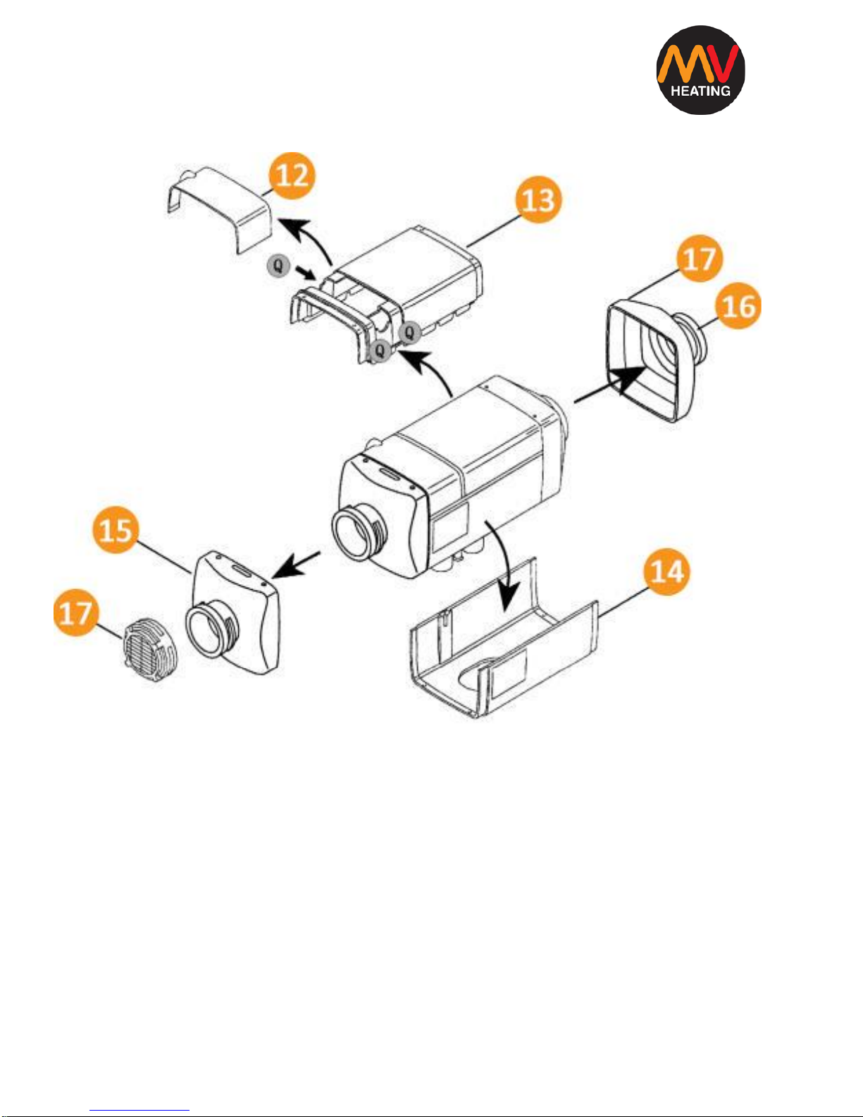
Case Assembly
Figure IV
12. Junction box cover 13. Top Case
14. Hot air outlet 15. Inlet Cover
16. Outlet Cover 17. Grill
+44 (0)23 8052 2345
10
MV Heating UK Ltd
Installation
The kit includes everything necessary for installation.

+44 (0)23 8052 2345
11
MV Heating UK Ltd
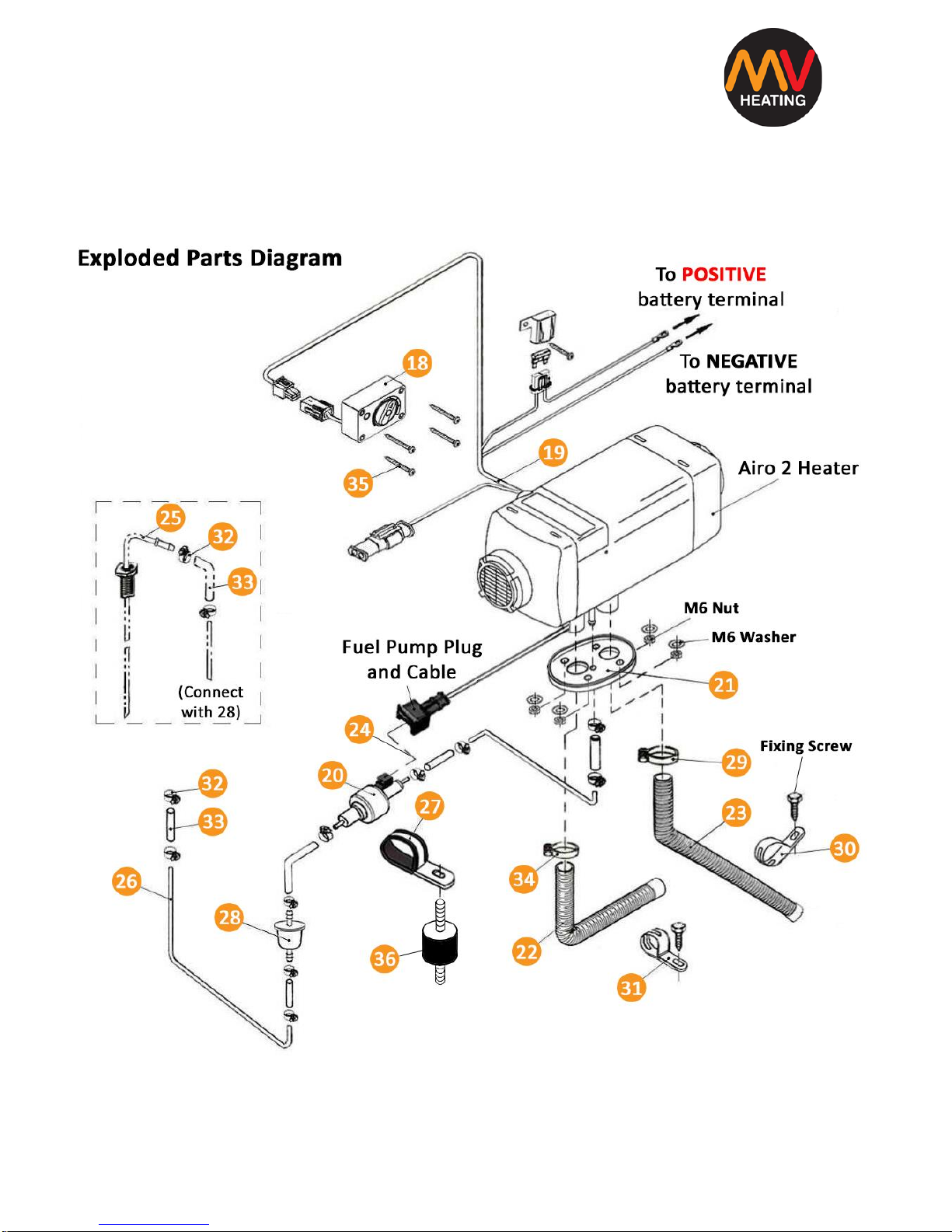
Figure V
18. Control Switch/Timer 19. Main Wire Harness
20. Fuel Pump 21. Mounting Gasket
22. Combustion Air Inlet Pipe 23. Exhaust Pipe
24. Fuel Pump Extension Loom 25. Fuel Standpipe
26. Fuel Pipe 27. Fuel Pump Bracket
28. Fuel Filter 29. Exhaust Pipe Clip
30. Exhaust Pipe Fixing Clip 31. Air Inlet Fixing Strap
32. Fuel Connector Hose Clip 33. Fuel Line Connector
34. Air Inlet Hose Clip 35. Control Fixing Screw
36. Anti-Vibration Mount (M6)
Figure V shows the diagram for installation. The position and ways of fixing of
various parts may vary from one vehicle/boat to another, but the general
principles remain the same.
Attention:
• Do not mount the heater near any flammable sources
• Do not install the heater in closed spaces without ventilation
• Do not place the heater near anything that can cause a blockage
• Do not mount the heater near any water sources and protect it from
any splashing
+44 (0)23 8052 2345
12
MV Heating UK Ltd
Installation of the Main Heater Body
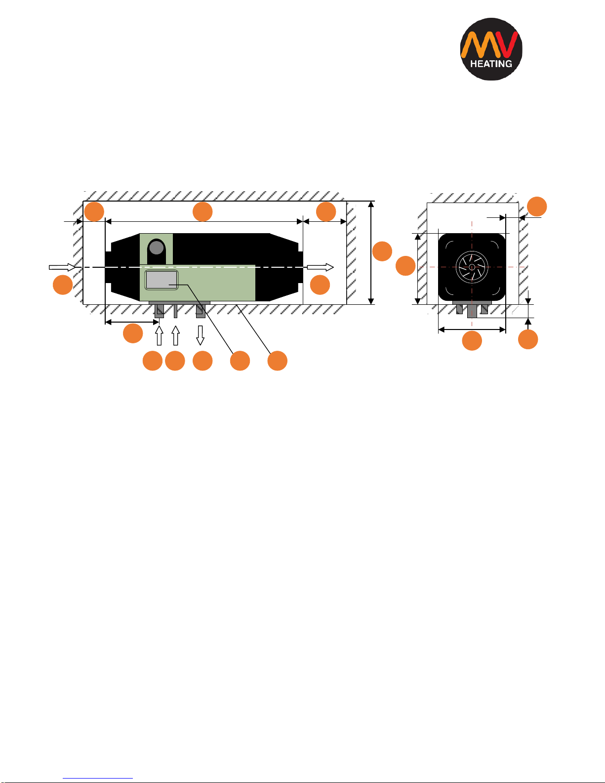
For the ease of servicing, fault finding and air flow it’s recommended that the
main body is placed in an area with easy access. Figure VI shows the
minimum distances required.
Figure VI
A. Air heating inlet B. Air heating outlet
C. Combustion air inlet D. Fuel inlet
E. Exhaust outlet F. Non-interference area
G. Information label H. Installation surface
I. Gasket
Choose a flat installation surface, any undulations could cause the case to
twist and will not ensure an even mount. Make sure there are no foreign
bodies between the bottom of the heater and the installation surface itself.
This will ensure a good seal between the two. File down any drill holes to
again ensure an even mounting surface. Tighten the M6 bolts provided to a
torque setting of 6Nm+1Nm.
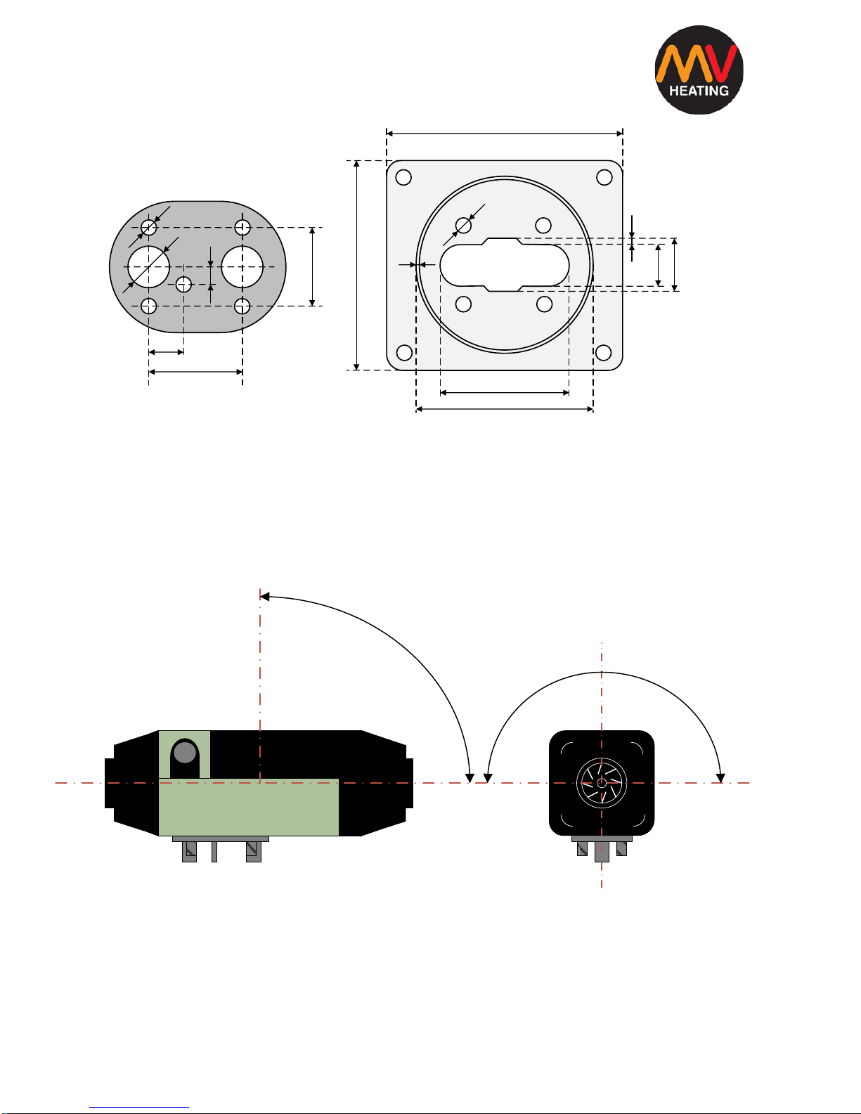
Figure VII shows the position of the installation holes. If the installation area
is less than 1.5mm thick a mounting plate will be required (Figure VIII).
32320 50
155
120
A B
C ED FG
29
120
20
121
+44 (0)23 8052 2345
13
MV Heating UK Ltd
A. Mounting Gasket B. Mounting Plate
Figure VII Figure VIII
If the heater is being reinstalled, a new gasket should be used.
Figure IX
148
7.5
170
85
125
2
5
25
35.5
7.5
26
12
44
18
55
DIMENSIONS: MM
A
B
0 - 90°
0 - 90°

+44 (0)23 8052 2345
14
MV Heating UK Ltd
The direction of the heater for installation is shown in figure IX.
Ensure you do not exceed the inclination angle or normal operation will be
affected.
After installation, make sure there is no friction between the fan and other
nearby parts to ensure smooth operation and make sure the heater label is
clearly visible for ease of maintenance in the future.
Air Inlet & Outlet
Make sure that the hot air outlet does not exit onto any parts affected by
heat and that it isn’t directed toward the flow of anything that can cause a
blockage, near splashing water or near the vehicles exhaust.
Correct Wrong
Figure X
Avoid re-entering of the supplied hot air into the inlet port (as shown in
Figure X). If no inlet pipe is required, make sure the grill is installed at the inlet
port instead (Figure IV no. 17).
 Loading...