


USER MANUAL
4G terminal
BROADBAND
2
MVG INDUSTRIES
User Manual
MUT.269.1.17.SATB.B
Notice
© Copyright 2017 by MVG Industries.
All rights reserved. No part of this document may be reproduced or distributed, in any form or by any method,
whether electronic or mechanical, including photocopying, recording or saving to any information storage or retrieval system, without written authorization from MVG Industries, 17 avenue
de Norvège, 91953 Courtaboeuf, France.
Trademarks
All product names and brands mentioned
in this document are trademarks or brand
names owned by their respective holders.
Conditions
In order to improve the design, reliability
or operating functions of its products,
MVG Industries reserves the right to
modify any of the items described in this
document without notice.
CONTACT
Telephone: +33(0) 1 69 29 02 47
Fax: +33(0) 1 69 29 02 27
Web: www.neptulink.com
Email: contact@neptulink.com
Usage precautions
•
To ensure a safe and correct operation,
please read this user manual and all precautions carefully before using the terminal.
•
Once the terminal is installed and in use,
make sure to maintain a minimum distance of
20 cm from the device.
•
Should a dysfunctional error occur, turn off
and unplug the terminal from the power supply immediately.
•
This manual must be kept with the product’s
end user. It must be transferred with the product if the terminal is passed on to a new
user.
•
The available functions may vary depending
on the terminal, the software version, or the
telephone service provider.
•
MVG Industries cannot be held responsible
for any performance problems or incompatibility issues resulting from user modifications to the operating system or the settings. Any attempt to customize the operating system may cause your terminal to malfunction.
Conventions used
in this manual
Please familiarize yourself with the symbols
used in these operating instructions before setting up your terminal.
SYMBOL
DESCRIPTION
Remarks, user tips or additional
infor-
mation.
Situation likely to damage your terminal.

3
EN
FCC statement
This device complies with Part 15 of the
FCC Rules. Operation is subject to the following two conditions: (1) this device may
not cause harmful interference, and (2) this
device must accept any interference received, including interference that may
cause undesired operation.
NOTE:
The grantee is not responsible for any
changes or modifications not expressly
approved by the party responsible for compliance. Such modifications could void the
user’s authority to operate the equipment.
This equipment has been tested and
found to comply with the limits for a Class B
digital device, pursuant to part 15 of the
FCC Rules. These limits are designed to
provide reasonable protection against harmful interference in a residential installation.
This equipment generates, uses and can
radiate radio frequency energy and, if not
installed and used in accordance with the
instructions, may cause harmful interference to radio communications. However,
there is no guarantee that interference will
not occur in a particular installation.
If this equipment does cause harmful interference to radio or television reception,
which can be determined by turning the
equipment off and on, the user is encouraged to try to correct the interference by
one or more of the following measures:
—Reorient or relocate the receiving antenna.
—Increase the separation between the equip-
ment and receiver.
—Connect the equipment into an outlet on a
circuit different from that to which the re-
ceiver is connected.
—Consult the dealer or an experienced ra-
dio/TV technician for help.

4
Contents
TECHNICAL FEATURES 05
PACK 06
PACK CONTENTS 06
DESCRIPTION OF THE TERMINAL 06
•
View of the interface with covers in position 06
•
View of the interface with covers removed 06
PREREQUISITES 07
•
Required SIM configuration 07
GETTING STARTED 07
•
Inserting the SIM card 07
•
Removing the SIM card 08
•
Electrical connections 08
•
Standard power connection 09
•
PoE connection 09
•
Switching off the terminal 10
•
Configuring the terminal 10
•
4G configuration 11
•
Unblock SIM card 12
•
Advanced configuration 13
Wi-Fi CONFIGURATION 13
•
Connecting to a Wi-Fi network 13
•
Disconnecting from a Wi-Fi network 14
•
Editing a Wi-Fi connection 14
•
Deleting a Wi-Fi connection 14
Wi-Fi ACCESS POINT CONFIGURATION 15
•
Connecting to the access point 15
•
Editing the access point 15
UPDATING THE TERMINAL 16
•
Manual updates 16
•
Remote updates
16
NETWORK CONFIGURATION 17
•
Changing IP address configuration 17
•
Configure DHCP server 17
CONFIGURING THE MODEM 18
•
Changing the modem configuration 18
OTHER 18
•
Rebooting the terminal 18
•
Resetting to factory defaults 18
•
Change language setting 18
TROUBLESHOOTING AND FAQ 19
APPENDIX 20
CONFIGURING YOUR COMPUTER FOR DHCP 20
CONTACTING TECHNICAL SUPPORT 21
EN
5
Technical features
TRANSMITTER - RECEIVER
Frequency bands
•
LTE with MIMO diversity:
•
UMTS (WCDMA), HSDPA, HSUPA,
Band 1 (2100 MHz)
DC-HSPA+ with diversity:
Band 2 (1900 MHz)
Band 1 (2100 MHz)
Band 3 (1800 MHz)
Band 2 (1900 MHz)
Band 4 (AWS) Band 3 (1800 MHz)
Band 5 (850 MHz)
Band 4 (AWS)
Band 7 (2600 MHz)
Band 5 (850 MHz)
Band 12 (700a)
Band 8 (900 MHz)
Band 13 (700c)
Band 20 (800DD)
Band 25 (1900+)
Band 26 (850+)
Band 29 (700d)
Band 41 (TD2500)
Distance from transmitter
1
Up to 20 NM
Antenna gain
2 dBi (± 1dB)
System weight
3.5 Kg
System dimensions
750 x 225 x 83 mm
SIM type (Dual SIM)
Mini SIM (a Micro SIM or Nano SIM may be used with a Mini SIM
adapter)
POWER SUPPLY FEATURES
Power supply
-
By cable: 12 VDC to 24 VDC
-
By passive PoE: 24 VDC
Power consumption
-
Start: 15 W
-
Operation: 12 W (max)
AMBIENT CONDITIONS
Operating temperature
-20°C to +60°C
Storage temperature
-40°C to +85°C
IP protection
IP66
INTERFACES
Data link
Ethernet Port and Wi-Fi 2.4 GHz 802.11b/g/n
PIN code and APN configuration
Via web interface
(1)
The actual distance will depend on your telecommunications service provider
6
Pack
Pack contents
The pack contains the following items:
•
4G terminal.
•
2- and 9-point terminal blocks.
•
User guide.
If any of these items is incorrect, missing or
damaged, please contact MVG Industries or
your retailer.
Please retain the packaging for future use,
should you need to return the product for repair.
Accessories other than those provided
may not be compatible with your terminal.
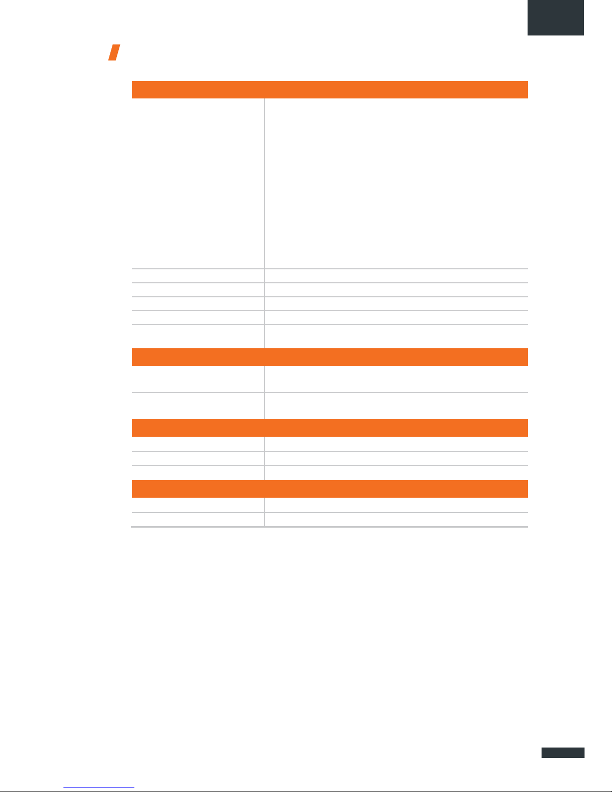
VIEW OF THE INTERFACE
WITH COVERS IN POSITION
Description
of the terminal
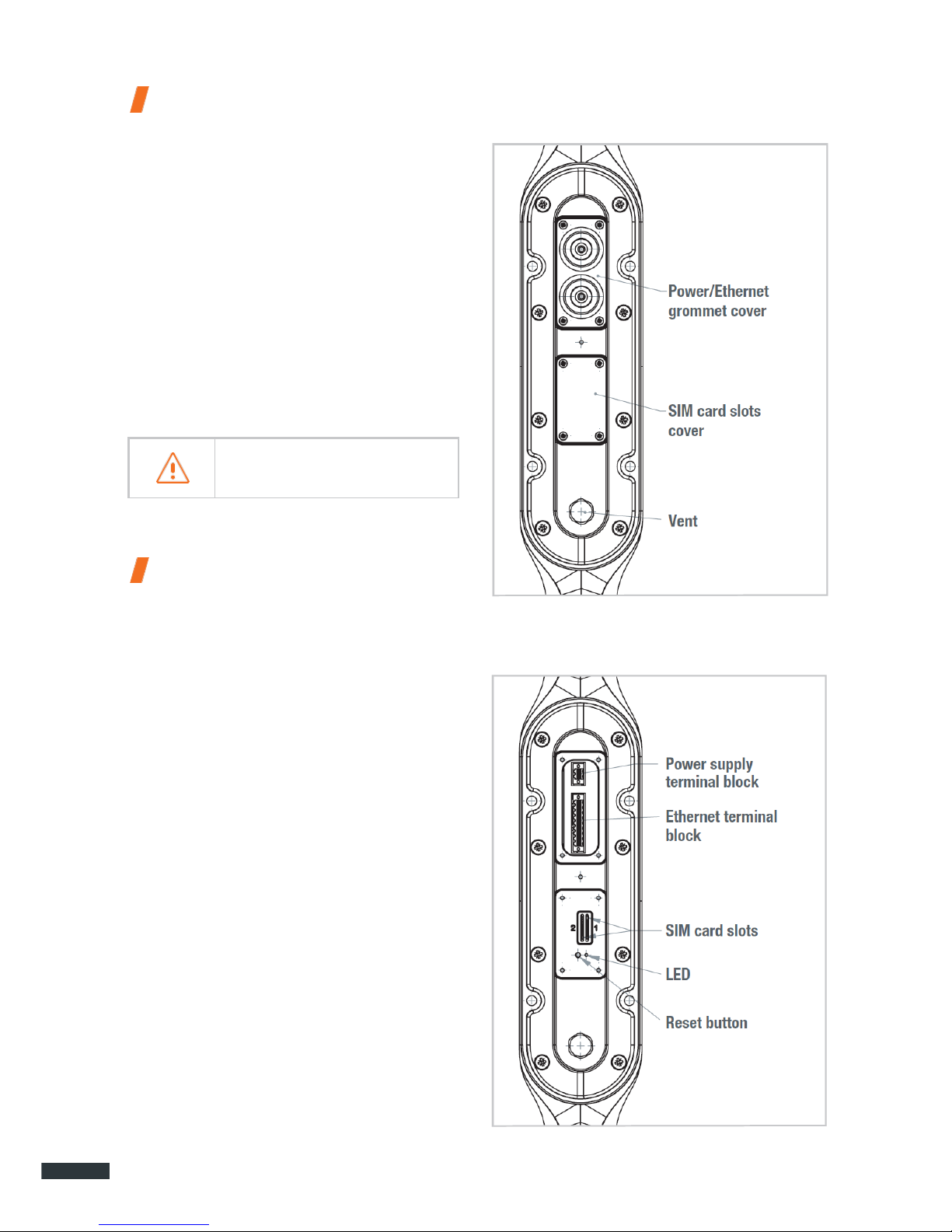
VIEW OF THE INTERFACE
WITH COVERS REMOVED
For best performance, the system must be
placed vertically (vent at bottom).
EN
7
Prerequisites
Ensure that you have the following items
ready before installing your terminal:
•
Active Internet access from a telephone
service provider (3G/4G data package).
•
Configuration settings for the SIM card(s) see below.
•
Computer configured for DHCP (Dynamic
Host Configuration Protocol, see appendix).
REQUIRED SIM CONFIGURATION
Depending on how your SIM card(s) are
configured, you will need one or more configuration settings to connect your terminal
to the Internet:
•
APN setting (Access Point Name).
•
PIN code (Personal Identification Number).
Your telephone service provider should have
given you all the necessary information to
enable you to connect to the Internet. Please
contact your service provider if you cannot find
this information.
Getting started
Your terminal can be configured in five steps:
➊
Insert the SIM card(s).
➋
Connect the terminal.
➌
Install the terminal on its mounting.
➍
Configure the terminal.
➎
Connect to internet.
Ask your telephone service provider for your
SIM card’s configuration settings before you
start.
Ensure that you check the network coverage and compare the offers available
from different service providers.
Stay at least 20 cm away from
the terminal when it is switched on.
INSERTING THE SIM CARD
Follow the steps below to insert either of
the SIM cards into your terminal.
This terminal is designed to accept one or
two Mini SIM cards.
Using an incompatible SIM card may
damage your terminal or your card.
➊
Switch the device off.
➋
Unscrew the center cover to access the
SIM card slots.
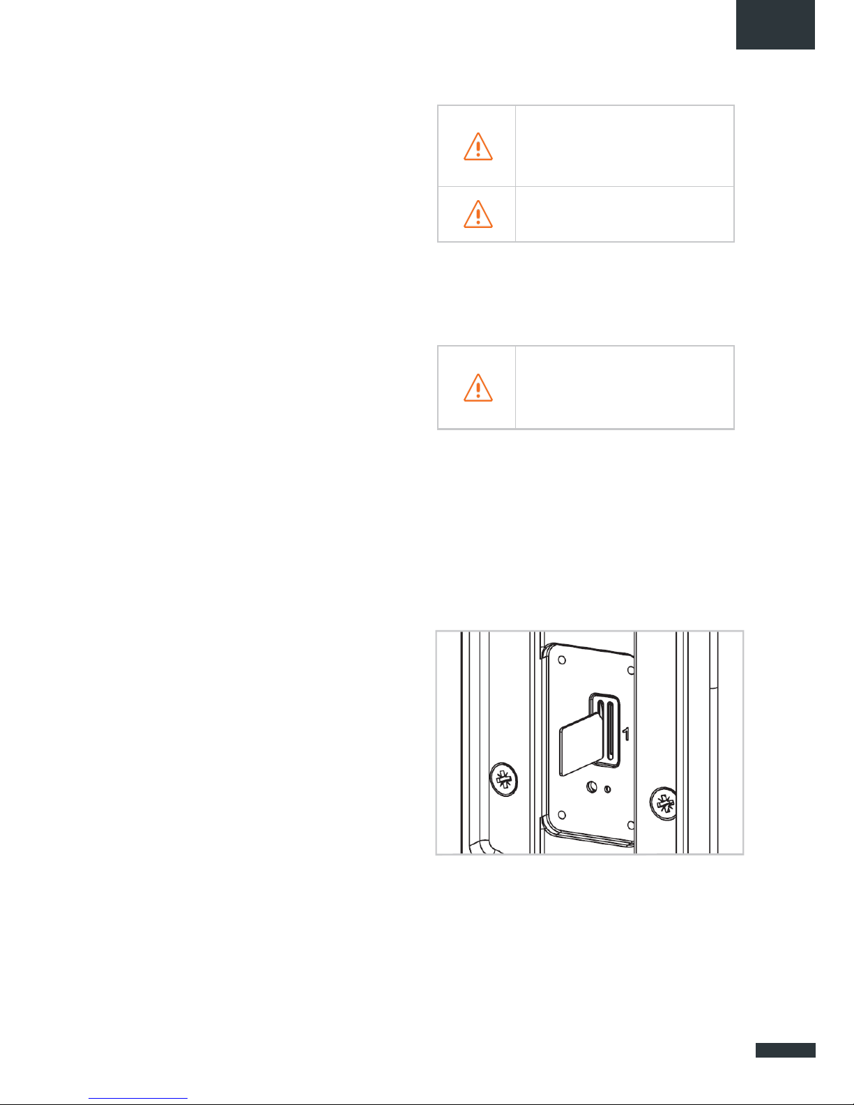
➌
Insert the SIM card into its slot. The chip
must be positioned with its cut-off edge
facing towards the terminal, as shown in
the figure below. When using only one chip,
insert it in the slot marked "1".
➍
Screw the cover back on.
➎
Switch the device back on.

8
Inserting a second SIM card:
REMOVING THE SIM CARD
Follow the steps below to remove either of
the SIM cards from your terminal.
➊
Switch the device off.
➋
Unscrew the center cover.
➌
Push in then release the SIM card to remove
it from the slot.
➍
Screw the cover back on.
➎
Switch the device back on.
ELECTRICAL CONNECTIONS
The terminal can be powered in two ways:
•
Power supply through the 12-24 V DC
socket.
•
24 VDC Power over Ethernet (PoE) connection using a passive injector.
Stay at least 20 cm away from the terminal when it is switched on.
If you have the PoE option, do not connect the PoE injector and the standard
power supply at the same time.
For passive PoE power supply, do not
connect/disconnect the power cable when
the injector is on.
Before installing the terminal blocks and
plugging in, the cable(s) used must be
threaded through the cover’s grommet (one
cable per gland).
The grommets are delivered unpierced. The
cable must be pushed through to open the
grommet at the center. When using PoE, do
not puncture the unused grommet.
Never remove the SIM card when the
terminal is switched on, as this may
damage the card and/or the terminal.
EMI Suppressor Ferrites must be installed on
each cable, at the output of the device.
Typical Impedance on each cable:
3 kOhm at 100 MHz
1.5 kOhm at 25 MHz
(e.g. 12 ferrites No. 7427007 from Würth
Elektronik).

EN
9
STANDARD POWER CONNECTION
Connect the 2 electrical wires to the 2-point
terminal block, as shown below:
Observe the polarity of the wires to avoid
damaging the terminal.
The guarantee does not cover any damage resulting from improper use.
Check that the connectors on the power
cable are compatible with your electrical
system.
Follow the steps below to connect the terminal
to the network and power supply in the
standard power supply configuration.
➊
Thread the cable through the grommet.
Do not use damaged power cords or
plugs.
Do not twist or damage the power cable.
➋
Prepare the wires in the cable and screw
them onto the 2-point terminal block, observing the polarities shown above.
➌
Install the 2-point terminal block in the
matching baseplate. Tighten the two holding screws fitted to the ends of the terminal
block.
PoE CONNECTION
Follow the steps below to connect the terminal to the network and power supply in
the PoE power supply configuration.
➊
Thread the cable through the grommet.
➋
Prepare the wires of the cable and screw
them into the 9-point terminal block, observing the color codes shown below.
➌
Plug the end of the cable into your PoE
injector’s Power+Data ("PD") port. Install
the 9-point terminal block in the matching
baseplate. Tighten the two holding screws
fitted to the ends of the terminal block.
The terminal must be supplied with a
voltage of between 12 and 24 VDC.

10
Ensure that the Ethernet connection
terminal block is fully screwed in.
Do not twist or damage the Ethernet
cable.
Do not use damaged Ethernet cables
or plugs.
Do not use the standard power cord.
➍
Connect the Data port on your PoE injec-
tor to the Ethernet port on your computer
or router.
➎
Switch on your PoE injector.
SWITCHING OFF THE TERMINAL
To switch off the terminal
•
Standard configuration: unplug the power
cord by unscrewing the screws on the 2point terminal block.
•
PoE configuration: switch off the PoE injector by unplugging its power cord.
CONFIGURING THE TERMINAL
Follow the instructions below to configure
and test the 4G connectivity.
Your computer must be configured for
DHCP. For instructions on DHCP configuration, please refer to your computer docu-
mentation or see the Appendix "Configuring
your computer
for DHCP".
➊
Switch your computer on if it is off.
The terminal will automatically assign an
IP address to your computer.
➋
Type the URL http://192.168.1.1 into the
address field of a browser such as Microsoft
Internet Explorer, Google Chrome or Mozilla
Firefox.
➌
The following login box will appear:
Type in admin as the user name and admin as
the password, all in lower case.
Click the Login button to proceed to the termi-
nal’s administration interface.
You can configure your terminal to connect to
Internet through a 4G or Wi-Fi connection.

EN
11
4G CONFIGURATION
➍
When the welcome page appears, click the
Network/Interfaces tab.
➎
Click Edit to edit the NeptuLink interface.
You are now ready to configure your terminal
for connection to the Internet.
In the "General" tab, use the SIM Selection
drop-down list to switch from one of the two
SIM cards to the other.
➏
For each SIM card, enter your telephone
service provider’s APN as well as the SIM
card’s PIN code in the correct tab (SIM 1 and
SIM 2 tabs).
If you enter an incorrect PIN code
three times, the SIM card will be
blocked. If this happens, contact your
service provider to obtain a PUK (PIN
Unblocking Key) code.
➐
Click Save & Apply to save and apply the
settings.
➑
Test your Internet connection.
Click the Status/Overview tab, then check
that the connection status appears as shown
below:
Your terminal is now configured to allow your
computer to access the Internet. Your terminal
will automatically establish an Internet connection when your computer requires access.
To access Internet from a computer connected
to your terminal, launch a web browser such
as Microsoft Edge or Google Chrome. The
browser should display a web page.

12
UNBLOCK SIM CARD
Follow the steps below to unblock your SIM
card.
➊
Click on the link “Click here to unblock
your SIM card” from the main panel.
➋
Unblock panel is displayed:
Type the 8-digit PUK code in the corresponding field.
➌
Type a new PIN code.
➍
Re-enter the new PIN code.
➎
Click Save & Apply to unblock your SIM
card.
To display the PUK code, click on

EN
13
ADVANCED CONFIGURATION
Click the Advanced Settings tab for the advanced settings (repeat steps ➍ and ➎ if
necessary to return to the Common Configuration interface).
Enable Roaming2: use this option to configure
the terminal for using data connections when
you change to a different country.
Depending on your subscription package,
sending or receiving data outside
your service provider’s coverage
zone may incur additional costs.
Contact your service provider for further
information.
Enable PIN Protection: activates or deactivates the PIN code protection function. If
the box is checked, you will need to re-enter
the PIN code for your SIM card.
(2)
Roaming: this service allows you to connect transparently to a mobile network in a foreign country when
you travel beyond your service provider’s coverage area.
Wi-Fi configuration
CONNECTING TO A Wi-Fi NETWORK
Follow the steps below to connect to a WiFi network.
Disconnect from 4G if it is active (Network/Interfaces tab and Disconnect
button for 4g-NeptuLink).
➊
Click the Network/WiFi Network tab on the
upper band.
➋
Click Scan to detect nearby Wi-Fi networks.
A list of available networks is displayed.
This may take a few seconds to complete.
➌
To join a network, click the Join Network
button for the network you want to access.
➍
A settings box is displayed:
Type the Wi-Fi network’s connection key in the
Passphrase field.
To display the key, click on
Entering a wrong password requires you to
restart the operation.
Entering a wrong password resets the access
point of the terminal.

14
➎
Then click Submit. A box containing net-
work connection information is displayed.
➏
Click Save & Apply to save and apply the
settings.
➐
Test your Internet connection.
Click the Status/Overview tab, then check
that the Active Connection status appears as
shown below:
Your terminal is now configured to allow your
computer to access the Internet.
To access Internet from a computer connected
to your terminal, launch a web browser such
as Microsoft Edge or Google Chrome. The
browser should display a web page.
DISCONNECTING
FROM A Wi-Fi NETWORK
Follow the steps below to disconnect from
a Wi-Fi network.
When the Wi-Fi network is no longer
in range, you are automatically
disconnected.
➊ Click the Network/Wi-Fi Network tab on the
upper band.
➋
Click Disable to disconnect from the Wi-Fi
network, as shown below.
➌
A confirmation box is displayed. Click OK
to confirm.
EDITING A Wi-Fi CONNECTION
Follow the steps below to edit an existing
Wi-Fi connection.
➊
Click the Network/WiFi Network tab on the
upper band.
➋
Click Edit to display the Wi-Fi network's
connection settings.
➌
Change the settings as required, then click
Save & Apply to save and apply the new
settings.
DELETING A Wi-Fi CONNECTION
Follow the steps below to delete an existing
Wi-Fi connection.
➊ Click the Network/WiFi Network tab on the
upper band.
➋
Click Remove to delete the Wi-Fi network
connection.
➌ A confirmation box is displayed. Click OK
to confirm.
Deleting a Wi-Fi connection will reset the
Wi-Fi access point of the terminal.

EN
15
Wi-Fi Access Point Configuration
CONNECTING TO THE ACCESS POINT
Follow the steps below to connect to a WiFi access point.
➊
Activate your device's Wi-Fi connection.
➋
Click the network named NeptuLink-4G.
A password may be required for network access.
Once connected, you can access Internet
without using the Ethernet cable.
You can also use your smartphone to
access your device’s web configuration
interface.
EDITING THE ACCESS POINT
Follow the steps below to edit the Wi-Fi access point.
Disconnect from 4G if it is active
(Network/Interfaces tab and
Discon-
nect button for 4g-NeptuLink).
➊
Click the Network/WiFi Network tab on the
upper band.
➋
Click Edit to display the Wi-Fi access point's
connection settings.
➌
A settings box is displayed:
From this box, you can change the following:
•
Communications channel.
Channel 6 is the default channel.

16
•
Transmit power.
Ensure you comply with
your country’s
current regulations.
•
SSID - access point identifier.
•
Network security settings.
➍
Click Save & Apply to save and apply the
new settings.
➎
Reboot the terminal.
Updating the Terminal
MANUAL UPDATES
Follow the steps below to update your
ter-
minal manually.
➊
Click the System/Flash Firmware tab on
the upper band.
➋
Click Browse then select the update file.
➌
Click Flash image to start the process.
➍
A confirmation box is displayed. Click
Proceed to start the update process.
REMOTE UPDATES
Follow the steps below to update your terminal remotely.
➊
Click the System/Firmware Upgrade tab
on the upper band.
➋
Click Check to check if a new version of the
software is available.
This may take a few seconds to complete.
➌
The result of this query may vary:
If there is a message showing:
•
"Not connected" means your terminal is not
connected to Internet and therefore cannot
check whether an update is available.
•
"No new firmware version available"
means that the terminal is already running
the latest update version.
•
If an update is available, a strip containing
information on the new version is displayed
on the lower part of the interface.
➍ Click Perform upgrade to start the process.
➎
A confirmation box is displayed. Click OK to
start the update process.

EN
17
Network Configuration
This section is intended for users with a
minimum knowledge in network configuration.
In case of wrong configuration, perform a
reset factory
“RESETTING TO FAC-
TORY DEFAULTS”
CHANGING IP ADDRESS CONFIGURATION
Follow the steps below to change your
terminal’s network configuration.
➊
Click the Network/Interface tab on the
upper band.
➋
Click Edit to edit the LAN interface
.
➌ From the "General" tab you can change
the network settings of the terminal (IP
address, netmask…).
➍
Click Save & Apply to save and apply the
new settings.
CONFIGURE DHCP SERVER
Follow the steps below to configure the
DHCP server.
➊ First follow the steps 1 and 2 of the pre-
vious section
“CHANGING IP ADDRESS CON-
FIGURATION“
.
➋
A section at the bottom of the General
tab
allows you to:
•
Enable/disable DHCP
•
Change IP address range
•
Define lease time.
➌
Click Save & Apply to save and apply
the
new settings.

18
Configuring the modem
CHANGING THE MODEM CONFIGURATION
In some specifics cases, it might be
necessary to change the modem configuration to suit it with your network service
provider.
Follow the steps below to change your
terminal’s modem configuration.
➊
Click the System/4G Modem tab on the
upper band.
➋
Select the firmware you want to use in the
Available Firmware drop-down list.
➌
Then, select one of the Available Configu-
rations for this firmware in the Available
Configuration drop-down list.
➍
Click Apply Configuration to start the
mo-
dem reconfiguration.
➎
A confirmation box is displayed. Click OK to
start the process.
This may take a few seconds to complete.
Other
REBOOTING THE TERMINAL
➊
Click the System/Reboot tab on the upper
band.
➋
Click Perform Reboot.
➌
A dialog box is displayed. Click OK to
re-
boot the terminal.
This can take 1-2 minutes.
RESETTING TO FACTORY DEFAULTS
➊
Click the System/Reset tab on the upper
band.
➋
Click Perform Reset.
➌
A dialog box is displayed. Click OK to reset
the terminal to factory defaults.
CHANGE LANGUAGE SETTING
➊
Click the System/Language tab on the up-
per band.
➋
Select a language from the language list.
➌
Click Save & Apply
.
The change will be applied when reloading the page from your web browser.

EN
19
Troubleshooting and FAQ
Should you experience any problems with your terminal, please use the table below to find a solution. If you can’t find the right solution, please contact our Technical Support team or your retailer.
PROBLEM DESCRIPTION
POSSIBLE CAUSE
POSSIBLE SOLUTION
Poor reception quality
You are too far away from any of your
service provider’s mobile network base
stations to receive a high-quality signal.
Check your network coverage.
To send and receive data, you must be
in a zone covered by your service
provider’s network.
SIM card error
Faulty or damaged SIM card.
Contact your mobile operator.
SIM card inserted incorrectly.
Insert your SIM card correctly following
the steps described under
”INSERTING
THE SIM CARD”.
SIM card blocked
You have entered the wrong PIN code.
Contact your service provider to obtain a
PUK code to unblock the SIM card.
Internet connection unavailable or slow
You are not in a 3G/4G service
coverage zone.
Check your network coverage.
You should see reception bars displayed
on your terminal's configuration interface,
together with “3G” or “4G”.
Weak reception signal.
Bring your vessel closer to land.
You have used up your Internet data
volume.
Contact your service provider to find
out how much data you have used.
If you have exceeded your data allowance,
your bandwidth may be reduced.
Cannot access the terminal’s
administration interface
The terminal is not switched on.
Check the power cord. Connect the
terminal.
If you are using the PoE configuration,
ensure that the injector is connected
to the power supply.
The connection status is
displayed as “Not Connected”
The SIM card settings you have entered
are incorrect.
Contact your service provider to obtain
the correct SIM card settings.
You have changed the SIM card settings.
Click “Connect” on the NeptuLink
interface or unplug and then reinsert the
power cable.
“Getting Carrier” connection
status continuously displayed
You are not in a 3G/4G service coverage
zone.
Check your network coverage.

20
Appendix
This appendix contains links to reference
documents explaining the technologies that
your terminal uses:
Document
Link
Technical features
NeptuLink_Datasheet_EN.pdf
Configuring your computer for
DHCP
To access your terminal, you will need to use
the DHCP (Dynamic Host Configuration Protocol). Your terminal will contact a DHCP server,
which automatically assigns an IP address to
the computer connected to the Ethernet port.
To activate DHCP, follow the steps below:
➊
Click Start , then Control Panel and
Network and Sharing Center.
➋
To display the network connections, click
the
Change card settings link on the lefthand side of the Network and Sharing
Center panel.
➌
Right-click the connection you wish to
change, then click Properties . Enter
an administrator password or confirm the
change if prompted to do so.
➍
Click Internet Protocol version 4 (TCP/
IPv4) then Properties.
➎
Click Obtain an IP address automatically.
➏
Click Obtain DNS Server addresses
automatically
.
➐
Click OK to close the dialog box. Your
computer is now configured for DHCP.

EN
21
Contacting Technical Support
You can contact our Technical Support team by telephone or
by email.
Please have the following information to hand before you contact us:
•
The serial number (found on the label at the back of your terminal or accessible via the
web interface).
•
Firmware version (found on the Status/Advanced page of the web interface).
COUNTRIES
OF INSTALLATION
TECHNICAL SUPPORT
France
Italy
Spain
Portugal
Greece
Croatia
Bosnia Hzg
Monaco
South Africa
MC Technologies
13, rue Jules Verne
29000 Quimper, France
http://www.mc-technologies.fr/
technique@mc-marine.com
+33.(0)2.98.64.04.84
Other countries
support@neptulink.com

MVG Industries
www.mvg-world.com
Technopôle Brest Iroise
Z. I. du Vernis
225, rue Pierre Rivoalon
29200 Brest
France
Tel : +33 (0)2 98 05 13 34
Fax : +33 (0)2 98 05 53 87
Head office
17, avenue de Norvège
91140 Villebon-sur-Yvette
France
Tel.: +33 (0)1 69 29 02 47
Fax: +33 (0)1 69 29 02 27
 Loading...