

Page 1
!"
!
!
!
!
!
!
!
!
!
!
MVE Automation Series
!
!
!
!
!
!
!
!
!
!
!
!
!
!
Quick Reference
G
uide
!
M
ultilingual
Page 2

MVE$Automation$Series$Quick$Reference$Guide
"
#"
!
!
!
!
!
!
!
Table$of$Contents
"
!
!
$%&'()*"+',-*!.!)/*!&-"
0!123/4"5"6&-*%&3"$/-,3"" 7"7"7"7"7"7"7"7"7"7"7"7"7"7"7"7"7"7"7"7"7"7"7"7"7"7"7"7"7"7"7"7"7"7"7"7"7"7"7"7"7"7"7"7"7"7"7"7"7"8"
9&**&:"$/-,3"5";3,)*%!)/ 3"5"$<41!)/3"6&--,)*!&-1""7"7"7"7"7"7"7"7"7"7"7"7"7"7"7"7"7"7"7"7"7"7"7"7"7"7"7"7"7"= "
0,>/%"$3(:?!-@"6&--,)*!&-1""7"7"7"7"7"7"7"7"7"7"7"7"7"7"7"7"7"7"7"7"7"7"7"7"7"7"7"7"7"7"7"7"7"7"7"7"7"7"7"7"7"7"7"7"7"7"A"
B'C(1*!-@"D,:2,%/*(%,"B3/%:"E,**!-@1"7"7"7"7"7"7"7"7"7"7"7"7"7"7"7"7"7"7"7"7"7"7"7"7"7"7"7"7"7"7"7"7"7"7"7"7"7"7"7"7"F"
B'C(1*!-@"G,H,3"/-'"G,H,3"B3/%:"E,**!-@1"" 7"7"7"7"7"7"7"7"7"7"7"7"7"7"7"7"7"7"7"7"7"7"7"7"7"7"7"7"7"7"7"7"7"7"7"IJK"
L!@<"G,H,3"B3/%:"E,**!-@"
L!@<"G,H,3"E,**!-@"
G&>"G,H,3"E,**!-@"
G&>"G,H,3"B3/%:"E,**!-@"
B'C(1*!-@"0!123/4"/-'"M(*2(*"E,**!-@1"""7"7"7"7"7"7"7"7"7"7"7"7"7"7"7"7"7"7"7"7"7"7"7"7"7"7"7"7"7"7"7"7"7"7"7"7"7"7"7"N"
6/3!?%/*!&-"&."D,:2,%/*(%,"$%&?,1"" 7"7"7"7"7"7"7"7"7"7"7"7"7"7"7"7"7"7"7"7"7"7"7"7"7"7"7"7"7"7"7"7"7"7"7"7"7"7"7"7"7"7"N"
$/11>&%'"/-'"E,)(%!*4"E,*(2"7"7"7"7"7"7"7"7"7"7"7"7"7"7"7"7"7"7"7"7"7"7"7"7"7"7"7"7"7"7"7"7"7"7"7"7"7"7"7"7"7"7"7"7"OJ#P"
B3/%:1"/-'"0,.!-!*!&-1"7"7"7"7"7"7"7"7"7"7"7"7"7"7"7"7"7"7"7"7"7"7"7"7"7"7"7"7"7"7"7"7"7"7"7"7"7"7"7"7"7"7"7"7"7"7"7"7"7"7"7"##"
6&-*/)*"+-.&%:/*!&-""7"7"7"7"7"7"7"7"7"7"7"7"7"7"7"7"7"7"7"7"7"7"7"7"7"7"7"7"7"7"7"7"7"7"7"7"7"7"7"7"7"7"7"7"7"7"7"7"7"7"7"7"7"# # "
Q,%:/-"*/?3,"&.")&-*,-*1" 7"7"7"7"7"7"7"7"7"7"7"7"7"7"7"7"7"7"7"7"7"7"7"7"7"7"7"7"7"7"7"7"7"7"7"7"7"7"7"7"7"7"7"7"7"7"7"7"7"# 8 "
+*/3!/-"*/?3,"&.")&-*,-*1"7"7"7"7"7"7"7"7"7"7"7"7"7"7"7"7"7"7"7"7"7"7"7"7"7"7"7"7"7"7"7"7"7"7"7"7"7"7"7"7"7"7"7"7"7"7"7"7"7"7"7"8="
E2/-!1<"*/?3,"&.")&-*,-*1"7"7"7"7"7"7"7"7"7"7"7"7"7"7"7"7"7"7"7"7"7"7"7"7"7"7"7"7"7"7"7"7"7"7"7"7"7"7"7"7"7"7"7"7"7"7"7"7"7"=A"
R%,-)<"*/?3,"&.")&-*,-*1"7"7"7"7"7"7"7"7"7"7"7"7"7"7"7"7"7"7"7"7"7"7"7"7"7"7"7"7"7"7"7"7"7"7"7"7"7"7"7"7"7"7"7"7"7"7"7"7"7"7"AF
"
!
!
NOTE: All MVE models are a Class 1, externally powered, continuous operation medical device.
They are not suitable for use with flammable anesthetics. This equipment has been tested and found
to comply with the limits for medical devices to IEC 601-1-2: [or EN 60601-1-1-2:2001 or Medical
Device Directive 93/42/EEC].
!
NOTE: MVE liquid nitrogen freezers should be installed by an authorized MVE Distributor per the
TEC 3000 Technical Manual, PN 13289499.
Page 3

MVE$Automation$Series$Quick$Reference$Guide
"
8"
!
!
!
!
!
!
!
!
3
4
!
1
5
6
!
!
2
7
8
!
!
9 10
!
!
!
!
D/?3,"#S""R%&-*"$/-,3"+',-*!.!)/*!&-
"
!
!
!
#" R%&-*"$/-,3" D<,".%&-*"2/-,3"!1"*<,"(1,%"!-*,%./),".&%"*<,"D;6"=PPP7"
B33"'!123/41"/-'")&-*%&31"/%,"3&)/*,'"&-"*<,".%&-*"2/-,3"
8" 0!123/4" B"A"T"8P"G!U(!'"6%41*/3"0!123/4"VG60W"1<&>1"*<,"H/3(,"&."/33")(%%,-*"
)&-'!*!&-1"!-)3('!-@"D,:2,%/*(%,"/-'"G!U(!'"X!*%&@,-"G,H,37" D<,"
'!123/4"/31&"1<&>1"/-4")(%%,-*"/3/%:")&-'!*!&-1"*</*":/4",T!1*7"
=" E*/%*"R!33" Y1,'"*&":/-(/334".!33"*<,".%,,Z,%">!*<"3!U(!'"-!*%&@,-7"D<!1"?(**&-":/4"
/31&"?,"2%,11,'"*&")3,/%"[.&@\".%&:"*<,"1*&%/@,"/%,/"*&"!-)%,/1,"
H!1!?!3!*47"
A" E*&2"R!33"""""""""""""""""""""""" Y1,'"*&":/-(/334",-'"*<,".!33!-@")4)3,7" B.*,%"2%,11!-@"*<!1"?(**&-]"*<,"
(-!*">!33"-&*"%,1(:,".!33!-@"(-*!3"*<,"3&>"3,H,3"1,**!-@"!1"%,/)<,']"&%"*<,"
[EDB^D"R+GG\"?(**&-"!1"2%,11,'7"
F" E,*(2" Y1,'"*&"/'C(1*"*<,"H/3(,"&."/33"(1,%"/'C(1*/?3,".(-)*!&-1"!-)3('!-@"
G,H,3]"G,H,3"B3/%:1]"D,:2,%/*(%,"B3/%:1]"$/11>&%'1]";*)7"
I" B3/%:"_(*," Y1,'"*&"1!3,-),"*<,"/('!?3,"/3/%:7" B31&"(1,'"*&"%,1,*"*<,"3/*)<!-@"
/3/%:"/.*,%"*<,"/3/%:")&-'!*!&-"!1")&%%,)*,'7"
K" Y2"B%%&>" "Y1,'"*&"!-)%,/1,"-(:?,%"H/3(,1"'(%!-@"[E,*(2\":&',17" $%,11"&-),"
*&"',)%,/1,"!-)%,:,-*/3347" L&3'"*<,"?(**&-"*&"1)%&33"*<%&(@<"H/3(,1"
U(!)`347" _/4"/31&"?,"(1,'"*&"*&@@3,"[a;E5XM\"&%"[MX5MRR\"H/3(,17"
N" 0&>-"B%%&>" "Y1,'"*&"',)%,/1,"-(:?,%"H/3(,1"'(%!-@"[E,*(2\":&',17" $%,11"&-),"
*&"',)%,/1,"!-)%,:,-*/3347" L&3'"*<,"?(**&-"*&"1)%&33"*<%&(@<"H/3(,1"
U(!)`347" _/4"/31&"?,"(1,'"*&"*&@@3,"[a;E5XM\"&%"[MX5MRR\"H/3(,17"
O" ;1)/2," Y1,'"*&",T!*"/-4":,-("&%"1,*(2".(-)*!&-7"
#P";-*,%" Y1,'"*&"E,3,)*"/-4":,-(".&%",'!*!-@"&%"1/H,"/-4"(1,%"/'C(1*/?3,"
1,**!-@7"
Page 4

MVE$Automation$Series$Quick$Reference$Guide
"
="
!
!
!
!
!
!
!
!
O"
#"
!
!
!
!
!
8"
A"
F
"
=
"
#P
"
!
!
!
I"
K" N"
!
!
!
!
!
D/?3,"8S""9&**&:"$/-,3"+',-*!.!)/*!&-"
!
!
!
#"D,:2"B
"
6&--,)*!&-".&%"D,:2,%/*(%,"B"2%&?,7
"
8"
D,:2"9"
6&--,)*!&-".&%"D,:2,%/*(%,"9"2%&?,7"
="
$&>,%"
6&--,)*!&-
"
6&--,)*!&-".&%"!-)&:!-@"2&>,%7"
A"
6M_"#"
6&--,)*!&-".&%"^EJANF")&::(-!)/*!&-1"!-*,%./),7"
F"
6M_"8"
^,'(-'/-*"6&--,)*!&-".&%"^EJANF")&::(-!)/*!&-1"!-*,%./),7"
I"
_/-(/3"R!33"
_/-(/3"R!33"?(**&-"(1,'"*&"&H,%%!',"*<,"D;6"=PPP"1&.*>/%,"/-'":/-(/334".!33 "*<,"
.%,,Z,%7
"
K"
0!1)%,,*"
B3/%:"
6&--,)*!&-1
"
D<,1,")&--,)*!&-1":&-!*&%"*<,"/3/%:1".&%"L!@<"D,:2"B]"G&>"G,H,3]"G&>"
9/**,%4]"/-'"GX8"E(22347"D<,4")/-"?,">!%,'"*&"/-4"/3/%:"141*,:"*</*"(1,1"
X&%:/334"M2,-"VXMW")&-*/)*17
"
N"
Q3&?/3"
B3/%:"
6&--,)*!&-1
"
D<,1,")&--,)*!&-1":&-!*&%"BGG"/3/%:17" D<,4")/-"?,">!%,'"*&"/-4"/3/%:"
141*,:"*</*"(1,1"X&%:/334"M2,-"VXMW"&%"X&%:/334"63&1,'"VX6W")&-*/)*17"
O"
_/!-"
L/%-,11"
6&--,)*!&-
"
6&--,)*!&-".&%"*<,":/!-">!%!-@"</%-,117" B33"&."*<,")&--,)*!&-1".&%"*<,"
1&3,-&!'"H/3H,1]"3!'"1>!*)<]"?42/11"1,-1&%]",*)7"/%,"3&)/*,'"<,%,7"
#P"
G,H,3"
6&--,)*!&-"
6&--,)*!&-".&%"3,H,3"1,-1!-@"141*,:7" G,H,3"1,-1!-@"!1"/)<!,H,'"H!/"'!..,%,-*!/3"
2%,11(%,"1,-1&%]"3&)/*,'"!-1!',"*<,"D;6"=PPP7" D<,"*(?,".%&:"*<,"3,H,3"
1,-1!-@"3!-,"&-"*<,".%,,Z,%")&--,)*1"<,%,7" D<,")&--,)*!&-"!1"/"#5N\"V=78::W"
M0"<&1,"?/%?7"
Page 5
A"
Dewar$Plumbing$Connections"
!
!
!
!
!
!
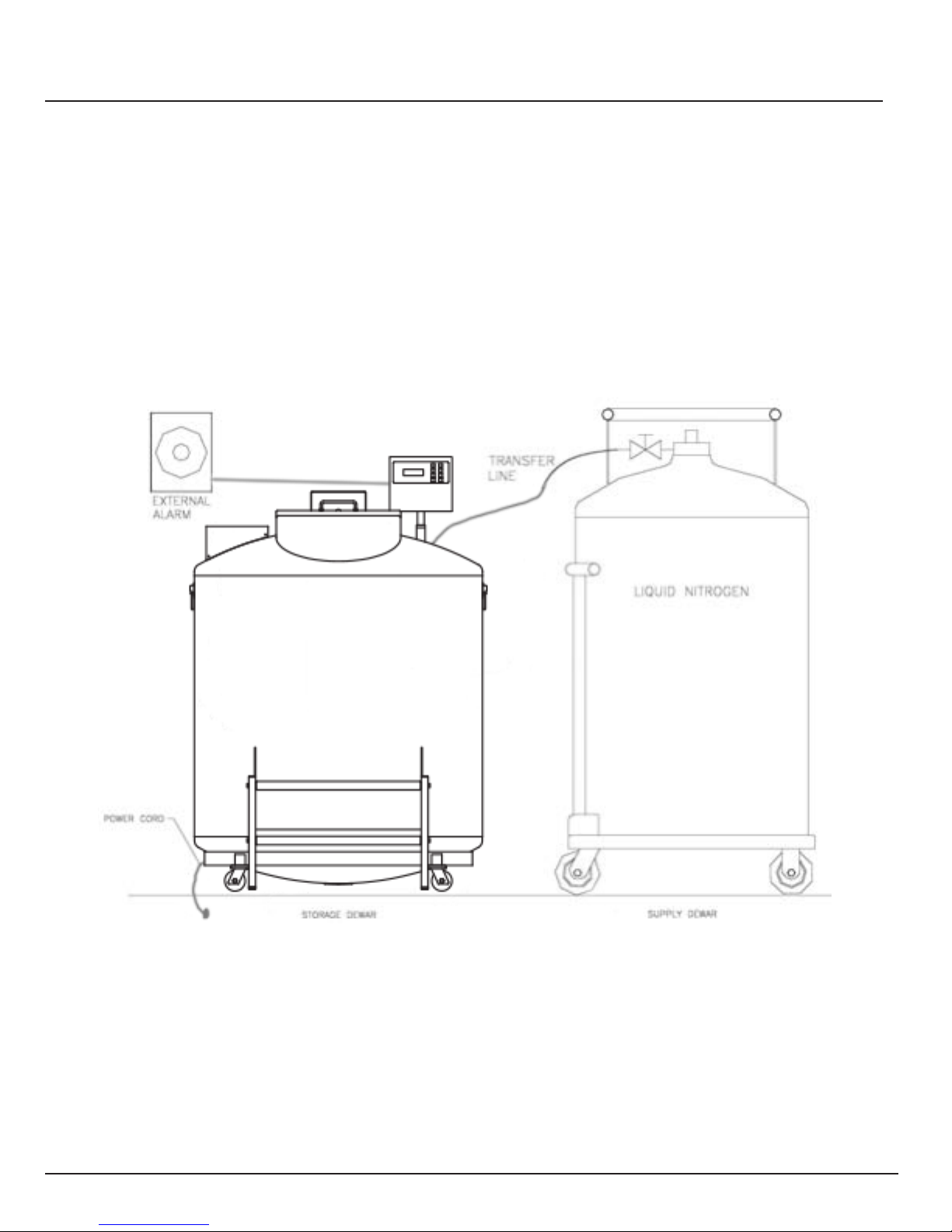
Connect a transfer line (included with freezer) from an LN2 supply tank to the fill connection at the rear of the freezer.
Optimum supply tank pressure is 22 to 35 psi (1.5 to 2.4 bar). Although the plumbing assembly has a 50 psi (3.45 bar) pres-
sure relief device, it is recommended that the supply tank be pressurized below 35 psi (2.4 bar) to reduce the LN2 “flash-off”
rate during filling and to maximize the cryogenic valve life. The supply line can be insulated to minimize LN2 transfer losses. After the transfer hose is securely coupled to the freezer and supply tank, ensure all connections are leak free by opening
the valve of the LN2 supply tank and apply a soap and water solution to each field joint. You should not see bubbles
forming
at
any joint. Wipe away excess soap and water when finished. Before removing the transfer hose, ensure the LN2 supply tank
valve is closed. Slowly and carefully loosen the transfer hose connection to vent any remaining pressure in the line before
disconnecting the hose.
!
!
!
Page 6

F"
MVE$Automation$Series$Quick$Reference$Guide
"
!
!
!
!
!
!
!
The following section describes how to adjust temperature alarm settings. At any time during the following procedure,
the user may exit the level by pressing the “Escape” button repeatedly, until the display returns to the “monitor” display
mode. After 30 seconds of inactivity, the controller will automatically return to the “monitor” display mode.
!
NOTE: Security Level 2 or higher is required to adjust temperature settings (see “Password and Security Setup”
section for details).
To exit any menu screen and return to the previous menu, press “ESC” key.
!
!
!
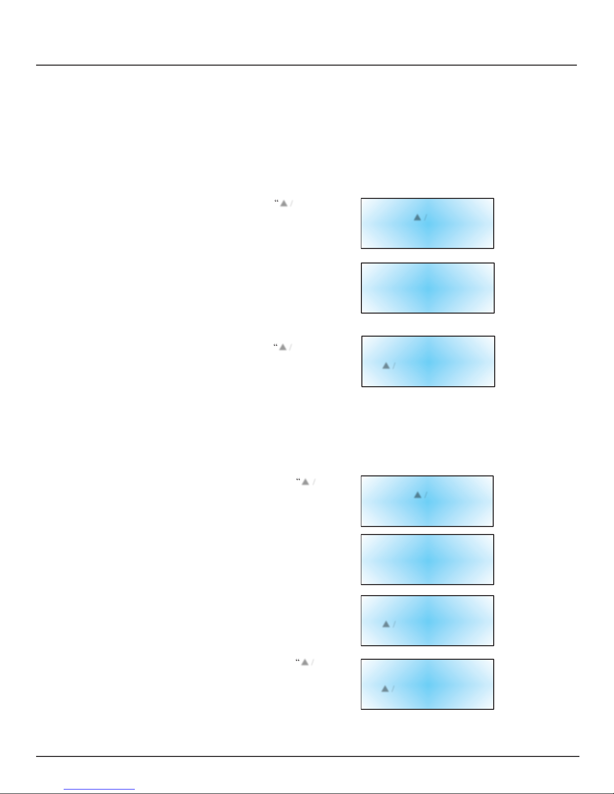
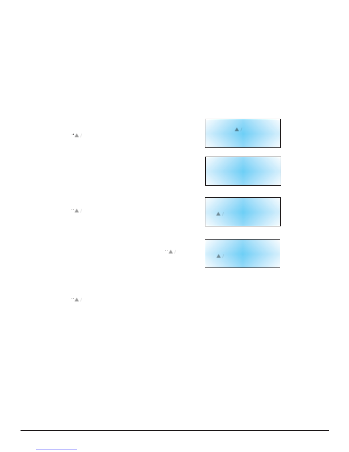
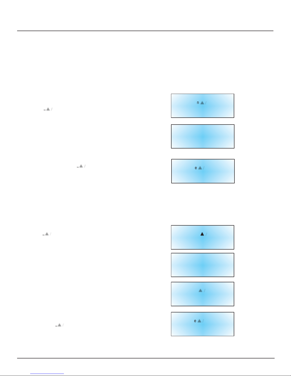
1. PRESS “SETUP”
The controller will prompt for a password. Use the “▲ / ▼”
keys to scroll to the appropriate number. Press “Enter” to move
cursor to the next position in the password.
!
!
!
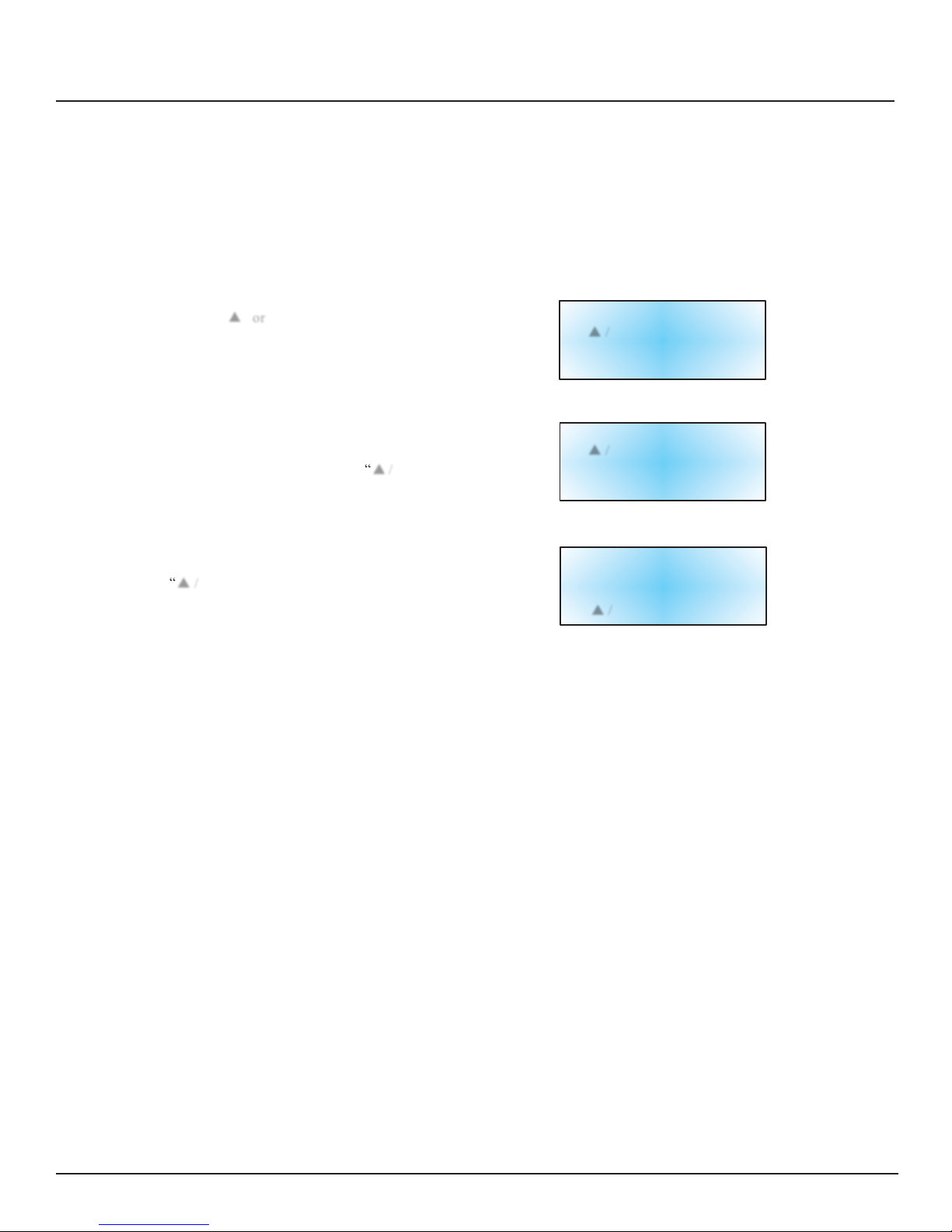
2. PRESS “ENTER”
The display will read “Temperature Menus”.
!
!
!
!
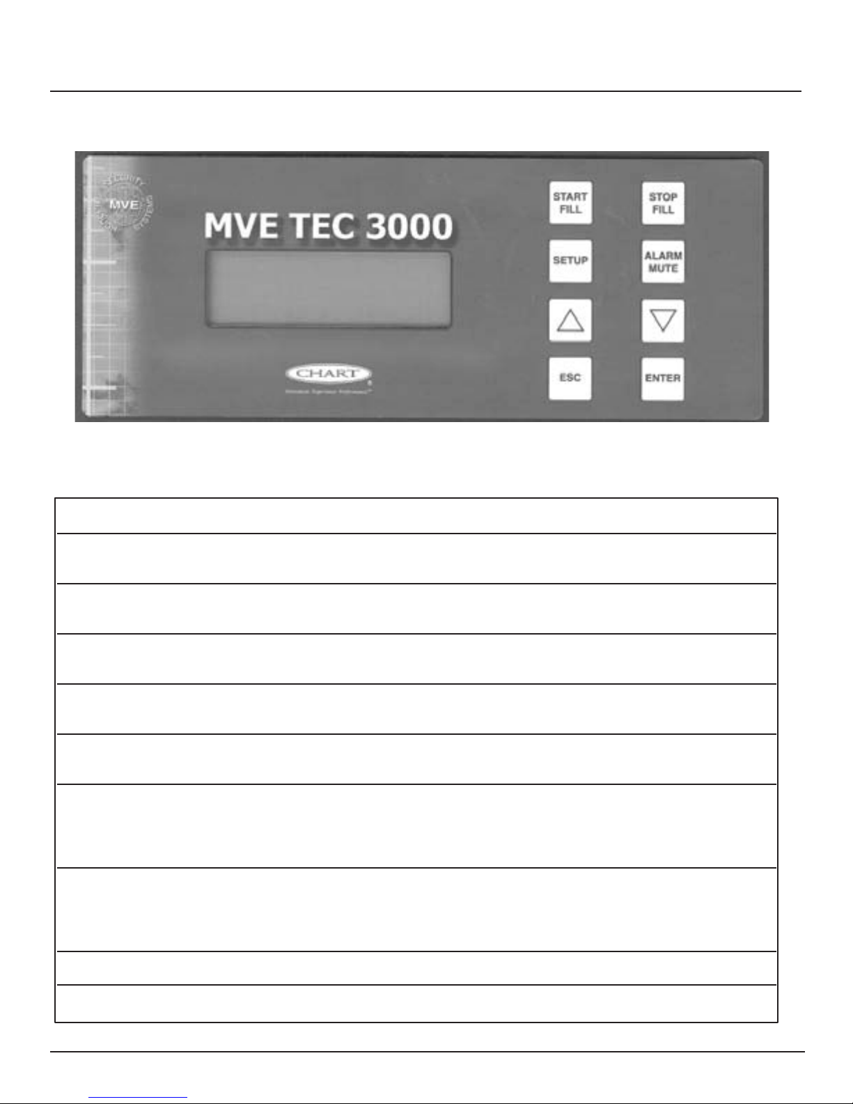
3. PRESS “ENTER”
The display will read “Temp A Menu”.
NOTE: To adjust Temp B settings, press “Setup”
instead of “Enter”.
!
!
!
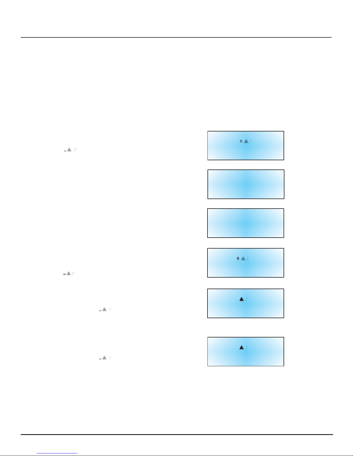
4. PRESS “ENTER”
The display will read “Temp A Enabled”.
NOTE: Probe A may be disabled now by pressing the
“▲ /
▼”
keys. Press “Enter” to save settings.
!
!
!
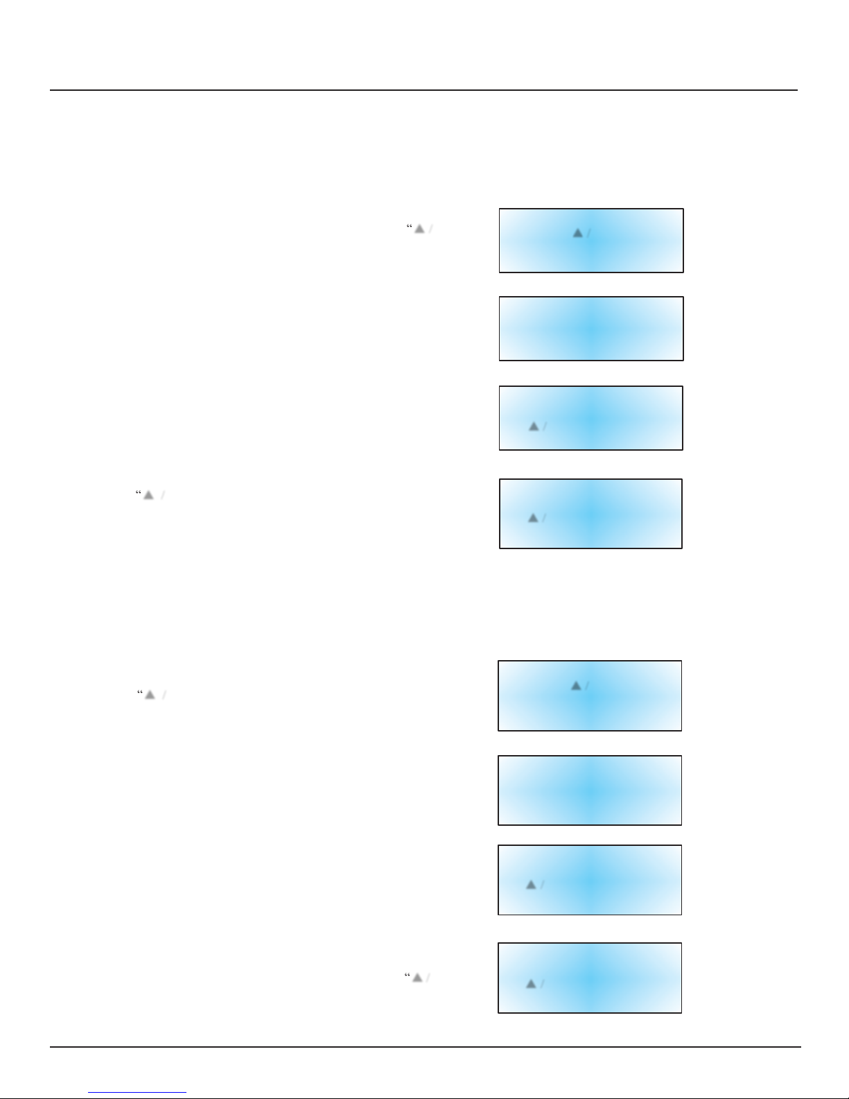
5. PRESS “SETUP”
Until Display Reads “Temp A High Alarm”. Use the “▲ / ▼”
keys to adjust the temperature. Hold either button to scroll
quickly. Press “Enter” to save settings.
!
!
!
6. PRESS “SETUP”
The display will read “Temp A Low Alarm”. Use the “▲ / ▼”
keys to adjust the temperature. Hold either button to scroll
quickly. Press “Enter” to save settings
High
User
Level
Required
Use ▲ / ▼ To
Enter
Password
0000
!
!
Press Enter
For
Temperature
Menus
Or
Press Setup
For
Next
Menu
!
!
Press Enter
For
Temp
A Menu
Or
Press Setup
For
Next Menu
!
!
Temp
A
Enabled
Use
▲ / ▼ To Adjust
Press Enter
To Save
!
!
!
Temp A High
Alarm
Use ▲ / ▼ To Adjust
Press Enter
To Save
-110.0°C
!
!
!
!
Temp A Low
Alarm
Use ▲ / ▼ To Adjust
Press Enter
To save
-200.0°C
!
!
After all adjustments are complete, wait 30 seconds and the TEC 3000 will return to the Main Display screen
indicating new settings are in effect.
Page 7
I"
MVE$Automation$Series$Quick$Reference$Guide
"
!
!
!
!
!
The following section describes how to adjust liquid nitrogen level settings and the high/low level alarms.
NOTE: Security Level 2 or higher is required to adjust the Level and Level Alarm settings (See “Password and Security
Setup” section for details).
!
NOTE: To exit any menu screen and return to the previous menu press “ESC” key.
!
HIGH LEVEL ALARM SETTING:
!
1. PRESS “SETUP”
The controller will prompt for a password. Use the “▲ /
▼”
keys
to scroll to the appropriate number. Press “Enter” to move the
cursor to the next position in the password.
!
!
2. PRESS “SETUP”
Until the display reads “Liquid Level Menus”.
!
!
!
!
!
!
2. PRESS “ENTER”
The display will read “High Level Alarm”. Use the “▲ / ▼” keys
to adjust the setting. Press “Enter” to save the settings. NOTE: No
level settings can be adjusted to less than .5 inches (14 mm) within
each other.
!
!
Higher User
Level
Required
Use
▲ / ▼
To
Enter
Password
0000
!
!
Press Enter
For
Liquid Level Menus
Or
Press Setup
For
Next Menu
!
!
!
High
Level
Alarm
8.0 in
Use
▲ / ▼
To Adjust
Press Enter
To Save
!
After all adjustments are complete, wait 30 seconds and the TEC 3000 will return to the Main Display screen
indicating new settings are in effect.
!
HIGH LEVEL SETTING:
!
!
1. PRESS “SETUP”
The controller will prompt for a password. Use the “▲ / ▼”
keys to scroll to the appropriate number. Press “Enter” to move
cursor to the next position in the password.
!
2. PRESS “SETUP”
Until the display reads “Liquid Level Menus”.
!
!
!
!
3. PRESS “ENTER”
The display will read “High Level Alarm”.
!
!
!
!
4. PRESS “SETUP”
The display will read “High Level Setpoint”. Use the “▲ / ▼”
keys to adjust the setting. Press “Enter” to save settings.
!
!
Higher User
Level
Required
Use
▲ / ▼
To
Enter
Password
0000
!
Press Enter
For
Liquid Level
Menus
Or
Press Setup
For
Next Menu
!
!
High
Level
Alarm
8.0 In
Use
▲ /
▼ To Adjust
Press Enter
To Save
!
!
High
Level
Setpoint
7.0 In
Use
▲ /
▼ To Adjust
Press Enter
To Save
!
After all adjustments are complete, wait 30 seconds and the TEC 3000 will return to the Main Display screen
indicating new settings are in effect.
Page 8
K"
MVE$Automation$Series$Quick$Reference$Guide
"
!
!
!
!
Adjusting$Level$&$Level$Alarm$Settings"
NOTE: To exit any menu screen and return to the previous menu, press “ESC” key.
!
LOW LEVEL SETTING
!
1. PRESS “SETUP”
The controller will prompt for a password. Use the “▲ / ▼”
arrow keys to scroll to the appropriate number. Press “Enter” to
move the cursor to the next position in the password.
!
!
!
2. PRESS “SETUP”
Until the display reads “Liquid Level Menus”.
!
!
!
!
3. PRESS “ENTER”
The display will read “High Level Alarm”.
!
!
!
4. PRESS “SETUP”
Until the display reads “Low Level Setpoint”. Use the
“▲ / ▼” keys to adjust the setting. Press “Enter” to save
settings.
!
Higher User
Level
Required
Use
▲ /
▼ To
Enter
Password
0000
!
!
Press Enter For
Liquid
Level
Menus
Or
Press Setup
For
Next Menu
!
!
High
Level
Alarm
8.0 In
Use
▲ /
▼ To Adjust
Press Enter
To Save
!
!
Low
Level
Setpoint
5.0 in
Use
▲ /
▼ To Adjust
Press Enter
To Save
!
After all adjustments are complete, wait 30 seconds and the TEC 3000 will return to the Main Display screen
indicating new settings are in effect.
!
!
LOW LEVEL ALARM SETTING:
!
1. PRESS “SETUP”
The controller will prompt for a password. Use the
“▲ / ▼” keys to scroll to the appropriate number. Press
“Enter” to move cursor to the next position in the password.
!
!
!
2. PRESS “SETUP”
Until the display reads “Liquid Level Menus”.
!
!
!
!
!
3. PRESS “ENTER”
The display will read “High Level Alarm”.
!
!
!
!
!
4. PRESS “SETUP”
Until the display reads “Low Level Alarm”. Use the “▲ / ▼”
keys to adjust the setting. Press “Enter” to save settings.
!
!
!
Higher User
Level
Required
Use
▲ /
▼ To
Enter
Password
0000
!
!
Press Enter
For
Liquid Level
Menus
Or
Press Setup
For
Next Menu
!
!
High
Level
Alarm
8.0 in
Use
▲ /
▼ To Adjust
Press Enter
To Save
!
!
!
Low
Level
Alarm
4.0 in
Use
▲ /
▼ To Adjust
Press Enter
To Save
Page 9
N"
MVE$Automation$Series$Quick$Reference$Guide
"
!
!
!
!
Adjusting$Display$And$Output$Settings
"
!
The units of measurement displayed by the TEC 3000 may be adjusted to accommodate the needs of the user.
Temperature measurement may be displayed in degrees Kelvin (°K), degrees Celsius (°C), or degrees Fahrenheit
(°F). The amount of liquid nitrogen in the freezer may be displayed in inches (in), millimeters (mm). In addition, the
amount of liquid nitrogen consumed by the freezer (liquid usage) may be shown on the display.
!
NOTE: Security Level 1 is required to adjust the display and output settings (See “Password and Security Setup”).
section for details).
!
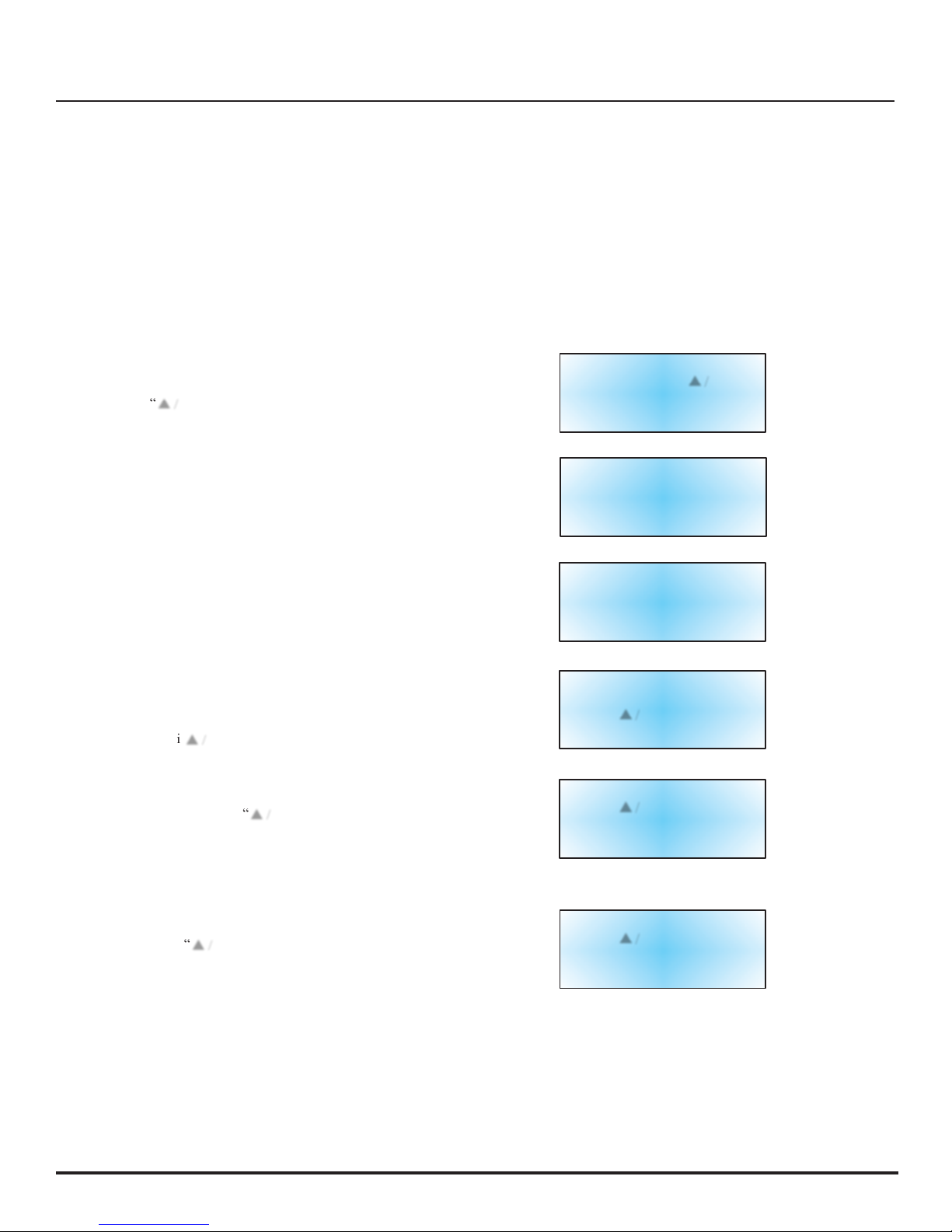
1. PRESS “SETUP”
The controller will prompt for a password. Use the
“▲ /
▼”
keys to scroll to the appropriate number. Press
“Enter” to move cursor to the next position in the password.
!
!
!
2. PRESS “SETUP”
Until the display reads “Display and Output”.
!
!
!
!
3. PRESS “ENTER”
The display will read “Temperature Units”. Use the
“▲ /
▼”
keys to toggle between °C (Celsius),
°F (Fahrenheit), or °K (Kelvin). Press “Enter” to save
settings.
!
!
4. PRESS “SETUP”
The display will read “Level Units”. Use the “▲ /
▼”
keys
to toggle between “in” (inches) or “mm” (millimeters).
Press “Enter” to save settings.
!
!
!
5. PRESS “SETUP”
The display will read “ Display Liquid Usage”. Use the
“▲ /
▼”
keys to select “ Yes” or “No”. Press “ Enter” to
save settings.
Higher User
Level
Required
Use ▲ / ▼ To
Enter
Password
0000
!
!
Press Enter
For
Display
And Output
Or
Press Setup
For
Next
Menu
!
!
!
Temperature
Units
°C
Use
▲ / ▼ To Adjust
Press Enter
To Save
!
!
!
Level
Units
In
Use ▲ / ▼ To Adjust
Press Enter
To Save
!
!
After all adjustments are complete, wait 30 seconds and the TEC 3000 will return to the Main Display screen
indicating new settings are in effect.
!
!
!
!
Calibration$of$Temperature$Probes"
!
Each of the temperature sensor probes (A and B) used with the TEC 3000 have been calibrated at the factory using
the “Low Temperature Range” method. This calibration method provides a level of accurancy of +/-1.8°F (+/-1°C)
when operated in the altitude range of 1000ft. to 1500ft. (305m to 457m). Further calibration should not be required
unless desired by the end user. Refer to the TEC 3000 Technical Manual for information on calibration methods
and procedures.
Page 10

O"
MVE$Automation$Series$Quick$Reference$Guide
"
!
!
!
Password$and$Security$Setup"
The TEC 3000 can store up to 10 different passwords. Each password can be assigned its own security level ranging
from Level 1 to Level 4. Table 3 below shows which settings can be changed with each security level. A security level
of 4 is required to adjust any password. The default (or “Global”) password for the TEC 3000 is “3456”. All
parameters may be adjusted by using this password. Record all passwords and security settings and store in a safe
place. NOTE: MVE recommends changing the global password, as it is common to all units. If the global password
has been forgotten, contact MVE Customer Service for details on how to reset passwords.
!
!
D/?3,"=S""E,)(%!*4"G,H,31"/-'"0,.!-!*!&-1"
!
FEATURE
LEVEL 1
LEVEL 2
LEVEL 3
LEVEL 4
Fill
Start X X X X
Fill
Stop X X X X
Alarm Mute
X X X X
Change
Display Units
X X X X
Temp
Settings
!
X X X
Level
Settings
!
X X X
T
ime/Date
!
X X X
Calibration
Probes
!
X X X
Change
Lang
uages
!
X X X
Hot Gas
Bypass Settings
!
X X X
OFAF
Setting
!
!
X X
Communication
Settings
!
!
X X
Programming
!
!
X X
Password Settings
!!!
X
!
!
1. PRESS “SETUP”
The controller will prompt for a password. Use the “▲ / ▼”
keys to scroll to the appropriate number. If setting up
passwords for the first time, use the default password of
“3456”. Press “Enter” to move cursor to the next position in
the password.
!
!
!
2. PRESS “ENTER”
The display will read “Temperature Menus”.
!
!
!
!
3. PRESS “SETUP”
Until the display reads “Password Menus”
!
!
!
!
!
4. PRESS “ENTER”
The display will read “Press Enter to change Global Password
or press Setup for Next”.
Higher
Use Level
Required Use ▲ / ▼ To
Enter
Password
0000
!
!
!
!
Press Enter
For
Temperature
Menus
Or
Press Setup
For
Next Menu
!
!
Press Enter
For
Password
Menus
Or
Press Setup
For
Next Menu
!
!
Press Enter
To
Change
Global
Password
Or Press
Setup
For Next
!
!
!
NOTE: The default setting for the “Global” password is “3456”. The “Global” password may be used to
change ALL settings for the TEC 3000.
Page 11
#P"
MVE$Automation$Series$Quick$Reference$Guide
"
!
!
!
!
Password$and$Security$Setup
"
!
5. PRESS “SETUP”
To scroll to the desired password number.
!
6. PRESS “ENTER”
To select the desired password number.
!
!
7. PRESS “ ▲” or “ ▼”
To scroll to the appropriate number. Press “Enter” to move
cursor to the next position in the password.
!
!
!
!
8. PRESS “ENTER”
After the desired password is selected. The display will now
read “Password X Level”. Use the “▲ /
▼”
keys to adjust
the security level.
!
!
!
9. PRESS “ENTER”
Display will read “Confirm New Password?”. Use the
“▲ /
▼”
keys to select “YES” or “NO”. Selecting “YES”
will save the new password and security setting. Selecting
“NO” will abort all changes.
!
!
!
10. PRESS “ENTER”
To save settings.
Password
1
Use ▲ / ▼ To Adjust
Press Enter
For Next
XXXX
!
!
!
Password
X Level
Use ▲ / ▼ To Adjust
Press Enter
For Next
Level
X
!
!
!
!
Confirm
New
Password?
NO
Use
▲ / ▼ To Adjust
!
!
At this time, the selected password and security level has been set and saved. Follow steps 7 - 11 to set additional
passwords and security levels, or press “Escape” repeatedly to return to the display screen. After 5 minutes of
inactivity, the controller will automatically return to the “monitor” mode. Use Table 4 to record passwords for future
reference.
Page 12

##"
MVE$Automation$Series$Quick$Reference$Guide
"
!
!
YEBS"
$<&-,S"
!
!
#JNPPJAN8J8AK="
;(%&2"
$<&-,"
S
"
R/TS
"
#JNNNJO=8J8AK="
R/TS"
bAA"VPW"#=AA"A8O"88A"
!
B1!/S"
$<&-,S"
!
!
bI#"8OK"AOA==="
!
!
R/TS
"
bI#"8OK"AOAIII"
!
!
!
!
!
Alarms$and$Descriptions
"
!
!
D/?3,"AS"B3/%:1"/-'"0,1)!2*!&-1"
!
Alarm Display
Description
High Temp A
The temperature of Probe A is above the user defined High Temperature
setting.
High Temp B
The temperature of Probe B is above the user defined High Temperature
setting.
Low Temp A
The temperature of Probe A is below the user defined Low Temperature
setting.
Low Temp B
The temperature of Probe B is below the user defined Low Temperature
setting.
High Level
The depth of LN2 inside the freezer is above the user defined High level setting.
Low Level
The depth of LN2 inside the freezer is below the user defined Low level setting.
Usage Warning
The consumption of LN2 has doubled (See TEC 3000 Technical Reference
Manual for details).
Usage Alarm
The consumption of LN2 has increased by a factor of 5 (See TEC 3000
Technical Reference Manual for details).
Fill Time
The amount of time required to complete a fill cycle exceeds the user defined
Fill Time setting.
Bypass Time
The amount of time required to complete a bypass cycle exceeds the user defined
Bypass Time setting.
Temp A Calibration
The temperature of Probe A is lower than absolute zero.
Temp B Calibration
The temperature of Probe B is lower than absolute zero.
Bypass Calibration
The temperature of the Bypass Probe is lower than absolute zero.
Low Battery
The voltage of the back up batteries has dropped below 21 volts.
Power Failure
The primary power has been disconnected for at least 60 minutes.
Lid Open
The lid on the freezer has been open longer than the user specified time.
Communication Loss
The controller has lost communications with the display.
!
If any alarms occur, contact your authorized MVE Distributor or
customer / technical service.
!
!
!
6(1*&:,%5D,)<-!)/3"E,%H!),S
"
!
,"
Page 13

#8"
MVE$Automation$Series$Ha n dbuch$mit$Kurzanleitung
"
!
!
!
!
!
!
!
Deutsch$Inhaltsverzeichnis
"
!
!
$%&'(`*?,1)<%,!?(-@"
B-Z,!@,"5"9,'!,-(-@1.,3'"" 7"7"7"7"7"7"7"7"7"7"7"7"7"7"7"7"7"7"7"7"7"7"7"7"7"7"7"7"7"7"7"7"7"7"7"7"7"7"7"7"7"7"7"7"7"7"#="
^c)`1,!*!@,1"$/-,3"5";3,`*%!1)<, "5"$<41!1)<,"d,%?!-'(-@,-"7"7"7"7"7"7"7"7"7"7"7"7"7"7"7"7"7"7"7"7"#A"
0,>/%"Q/1/-1)<3c11," 7"7"7"7"7"7"7"7"7"7"7"7"7"7"7"7"7"7"7"7"7"7"7"7"7"7"7"7"7"7"7"7"7"7"7"7"7"7"7"7"7"7"7"7"7"7"7"7"7"7"7"#F"
9,1*!::(-@"',%"D,:2,%/*(%/3/%:,!-1*,33(-@,-""7"7"7"7"7"7"7"7"7"7"7"7"7"7"7"7"7"7"7"7"7"7"7"7"7"7"7"7"7"7"7"#I"
9,1*!::(-@"',%"E*(.,-J"(-'"E*(.,-/3/%:,!-1*,33(-@,-"7"7"7"7"7"7"7"7"7"7"7"7"7"7"7"7"7"7"7"7"7"7"#K"J" #N"
B3/%:,!-1*,33(-@".c%"<&<,"E*(.,"
L&<,"E*(.,-,!-1*,33(-@"X!,'%!@,"
E*(.,-,!-1*,33(-@"B3/%:,!-1*,33(-@"
.c%"-!,'%!@, "E*(.,"
9,1*!::(-@"',%"B-Z,!@,J"(-'"B(1@/?,,!-1*,33(-@,-"" 7"7"7"7"7"7"7"7"7"7"7"7"7"7"7"7"7"7"7"7"7"7"7"7"7"7"#O"
e/3!?%!,%(-@"',%"D,:2,%/*(%:,11.c<3,%"7"7"7"7"7"7"7"7"7"7"7"7"7"7"7"7"7"7"7"7"7"7"7"7"7"7"7"7"7"7"7"7"7"7"7"7"7"7"#O"
;!-%!)<*,-"',%"$/11>&%*J"(-'"E!)<,%<,!*1,!-1*,33(-@,-""7"7"7"7"7"7"7"7"7"7"7"7"7"7"7"7"7"7"7"7"7"7"8P"J"8#"
B3/%:.&%:,-"(-'"0,.!-!*!&-,-" 7"7"7"7"7"7"7"7"7"7"7"7"7"7"7"7"7"7"7"7"7"7"7"7"7"7"7"7"7"7"7"7"7"7"7"7"7"7"7"7"7"7"7"7"7"88"
e&-*/`*" 7"7"7"7"7"7"7"7"7"7"7"7"7"7"7"7"7"7"7"7"7"7"7"7"7"7"7"7"7"7"7"7"7"7"7"7"7"7"7"7"7"7"7"7"7"7"7"7"7"7"7"7"7"7"7"7"7"7"7"7"7"7"7"88
"
!
HINWEIS: Alle MVE-Modelle stellen medizinische Geräte der Klasse 1 im Dauerbetrieb und mit
externer Stromversorgung dar. Sie eignen sich nicht für die gemeinsame Verwendung mit
entflammbaren Anästhetika. Diese Geräte wurde einer Überprüfung unterzogen, und es wurde
festgestellt, dass sie die Anforderungen der Richtlinien bezüglich medizinischer Geräte gemäß
IEC 601-1-2: [oder EN 60601-1-1-2:2001 oder der europäischen Richtlinien für Medizinprodukte
93/42/EEC] erfüllen.
!
!
!
!
HINWEIS: MVE-Flüssigstickstoff-Freezer sollten nur von autorisiertem MVE-Personal gemäß
dem Technischen Handbuch TEC 3000, Teilenummer 13289499, installiert werden.
Page 14
#="
MVE$Automation$Series$Ha n dbuch$mit$Kurzanleitung
"
!
!
!
!
!
!
!
!
3
4
!
1
5
6
!
!
2
7
8
!
!
9 10
!
!
!
!
D/?,33,"#S""R(-`*!&-,-"',1"H&%',%1,!*!@,-"$/-,31
"
!
!
!
#" d&%',%1,!*!@,1"$/-,3" 0/1"H&%',%1,!*!@,"$/-,3"!1*"'!,"9,-(*Z,%?,'!,-(-@1.3f)<,".c%"D;6"=PPP7"B33,"B-Z,!@,J"
(-'"9,'!,-,3,:,-*,"?,.!-',-"1!)<"/(."',:"H&%',%1,!*!@,-"$/-,37"
8" B-Z,!@," B"A"T"8P"G!U(!'"6%41*/3"0!123/4"VG60W"Z,!@*"',-"g,%*"/33,%":&:,-*/-,-";!-1*,33( - @ , - "
,!-1)<3!,h3!)<"',%"D,:2,%/*(%"(-'"',1"R3c11!@1*!)`1*&..>,%*,1"/-7"0!,"B-Z,!@,"Z,!@*"
@,@,?,-,-./331"/()<"B3/%:1!*(/*!&-,-"/-7"
=" E*/%*"R!33" g!%'".c%"'!,":/-(,33,"Rc33(-@"',1"R%,,Z,%1":!*"R3c11!@1*!)`1*&.."H,%>,-',*7"
VE*/%*,-"' , 1" 0!,1,%"e-&2."`/--"/()<"?,*f*!@*">,%',-]"(:"i0/:2.["/(1"',:"E2,!)<,%?,%,!)<"
Rc33H&%@/-@1W" Z(",-*.,%-,-"(-'"'/'(%)<"'!,"E!)<*?/%`,!*">!,',%"Z("@,>f<%3,!1*,-7"
A" E*&2"R!33" g!%'".c%"'!,":/-(,33,"9,,-'(-@"',1"Rc33Z4`3(1"H,%>,-',*7" 0(%)<"9,*f*!@,-"'!,1,1"
V9,,-',-"',1" e-&2.,1">!%'"`,!-,">,!*,%,"Rc33(-@"'(%)<"'!,";!-<,!*"H&%@,-&::,-]"?!1"'!,"
Rc33H&%@/-@1W" -!,'%!@,"E*(.,-,!-1*,33(-@",%%,!)<*"&',%"',%"e-&2."iEDB^D"R+GG["?,*f*!@*">&%',-"!1*7"
F" E,*(2" g!%'".c%"'!,"B(1%!)<*(-@"',1"g,%*1"/33,%"H&:"9,-(*Z,%"/-2/11?/%,-"
VB-2/11(-@"',%" R(-`*!&-,-"H,%>,-',*]",!-1)<3!,h3!)<"',%"E*(.,]"',%"E*(.,-/3/%:,]"',%"
R(-`*!&-,-W" D,: 2,%/*(%/3/%:,]"',%"$/11>j%*,%",*)7"
I" B3/%:"_(*," g!%'"Z(:"B(11)</3*,-"',1"/`(1*!1)<,-"B3/%:1"H,%>,-',*7" g!%'"/()<"Z(%"
VB(11)</3*,-" k(%c)`1,*Z(-@"',1"E2,%%/3/%:1"H,%>,-',*]"1&?/3'"',%"B3/%:Z(1*/-'"
',1"B3/%:1W" `&%%!@!,%*">(%',7"
K" X/)<"&?,-" g!%'"Z(%";%<j<(-@"',%"k/<3,->,%*,"?, !"' , - "iE , *( 2 “J_&'!"H,%>,-',*7"
Z,!@,-',%"$.,!3" 9,*f*!@,-"E!,"'!,"D/1*,",!-:/3"Z(%"d,%%!-@,%(-@"(:",!-,-"C,>,!31"<j<,%,-"g,%*7"
L/3*,-"E!,"',-"e-&2."@,'%c)`*]"(:"!:"E)<-,33'(%)<3/(."/33,"Z(%"B(1>/<3"1*,<,-',-"
g,%*,"Z("'(%) < 3/( .,-7" e/--"/()<"Z(:"Y:1)</3*,-"Z>!1)<,-"',-"g,%*,-"ilB5X;+X["
&',%"iMX5MRR["H,%>,-',*">,%',-7"
N" X/)<"(-*,-" g!%'"Z(%"d,%%!-@,%(-@"',%"k/<3,->,%*, "? , !"' , - "iE , *( 2 “J_&'!"H,%>,-',*7" 9,*f*!@,-"
Z,!@,-',%"$.,!3" E!,"'!,"D/1*,",!-:/3"Z(%"d,%%!-@,%(-@"(:",!-,-"C,>,!31"<j<,%,-"g,%*7"L/3*,-"E!,"',-"
e-&2."@,'%c)`*]"(:"!:"E)<-,33'(%)<3/(."/33,"Z(%"B(1>/<3"1*,<,-',-"g,%*,"Z("
'(%)<3/(.,-7"e/--"/()<"Z(:"Y:1)</3*,-"Z>!1)<,-"',-"g,%*,-"ilB5X;+X["&',%"
iMX5MRR["H,%>,-',*">,%',-7"
O" ;1)/2,"V9,,-',-W" g!%'"Z(:"9,,-',-",!-,1"?,3!,?!@,-"_,-c1"&',%",!-,%"?,3!,?!@,-"E,*(2JR(-`*!&-"
H,%>,-',*7"
#P"";-*,%"V;!-@/?,W" g!%'"Z(%"B(1>/<3",!-,1"?,3!,?!@,-"_,-c1"Z(%"9,/%?,!*(-@"&',%"Z(:"E2,!)<,%-",!-,%"
?,3!,?!@,-"/-2/11?/%,-";!-1*,33(-@"H,%>,-',*7"
Page 15

#A"
MVE$Automation$Series$Ha n dbuch$mit$Kurzanleitung
"
!
!
!
!
!
!
!
!
O"
#"
!
!
!
!
!
8"
A"
F
"
=
"
#P
"
!
!
!
I"
K" N"
!
!
!
!
!
D/?,33,"8S""R(-`*!&-,-"',1"%c)`1,!*!@,-"$/-,31
"
!
!
!
#" D,:2"B" d,%?!-'(-@".c%"D,:2,%/*(%:,11.c<3,%"B"
8" D,:2"9" d,%?!-'(-@".c%"D,:2,%/*(%:,11.c<3,%"9"
=" E*%&:H,%?!-'(-@" d,%?!-'(-@".c%"Z(.3!,h,-',-"E*%&:"
A" 6M_"#" d,%?!-'(-@".c%"e&::(-!`/*!&-1&?,%.3f)<,"^EJANF"
F" 6M_"8" ^,'(-'/-*,"d,%?!-'(-@".c%"e&::(-!`/*!&-1&?,%.3f)<,"^EJANF"
I" _/-(,33,"Rc33(-@" d,%>,-'(-@"',1"e-&2.,1".c%"'!,":/-(,33,"Rc33(-@]"'!,"'!,"Rc33(-@"'(%)<"'!,"
D;6"=PPPJE&.*>/%,",%1,*Z*]"(-'"Z(%":/-(,33,-"Rc33(-@"',1"R%,,Z,%17"
K" Y-/(..f33!@," 0!,1,"d,%?!-'(-@,-"`&-*%&33!,%,-"'!,"B3/%:,!-1*,33(-@,-".c%"L&<,"D,:2,%/*(%"B]"X!,'%!@,"
B3/%:H,%?!-'(-@,-" E*(.,]"X!,'%!@,-"9/**,%!,1*/*(1"( - ' "' !, "G X8Jd,%1&%@(-@7" 87E!,"`j--,-":!*"C,',:"
B3/%:141*,:"H,%?(-',-">,%',-]"'/1"m..-,%"VXMW"/:"^,3/!1"H,%>,-',*7"
N" Q3&?/3," 0!,1,"d,%?!-'(-@,-"`&-*%&33!,%,-"BGG;"B3/%:,7" E!,"`j--,-":!*"C,',:"B3/%:141*,:"
B3/%:H,%?!-'(-@,-" H,%?(-',-">,%',-]"'/1"m..-,%"VXMW"&',%"E)<3!,h,%"VX6W"/:"^,3/!1"H,%>,-',*7"
O" L/(2*`/?,3?/(:J" d,%?!-'(-@".c%"',-"L/(2*`/?,3?/(:7"B33,"d,%?!-'(-@,-".c%"'!,"_/@-,*H,-*!3,]"',-"
H,%?!-'(-@" e3/22,-1)</3*,%]"',-"942/11JE,-1&%",*)7"?,.!-',-"1!)<"<!,%7"
#P""E*(.,-H,%?!-'(-@" d,%?!-'(-@".c%"'/1"E*(.,-1,-1&%141*,:7"0!,"E*(.,-:,11(-@">!%'":!*<!3.,",!-,1"
'!..,%,-Z!,33,-"0%()`1,-1&%1",%:!**,3*]"',%"!-"D;6"=PPP"!-*,@%!,%*"!1*7" 0!,"d,%?!-'(-@"Z(%"
^j<%,"',%"E*(.,-:,113,!*(-@"!:"R%,,Z,%"?,.!-',*"1!)<"<!,%7" 9,!"',%"d,%?!-'(-@"</-',3*",1"
!)<"(:",!-,-"M0J^j<%,-/-1)<3(11":!*",!-,:"0(%)<:,11,%"H&-"=]8"::"V#5N\W7"
Page 16

#F"
Dewar$Gasanschlüsse"
!
!
!
!
!
!
Schließen Sie den Transferschlauch (im Lieferumfang des Freezers enthalten) von einem LN2-Versorgungstank zum
Füllanschluss hinten am Freezer an. Der optimale Druck des Versorgungstanks beträgt 22 bis 35 psi (1,5 bis 2,4 bar). Der
Gasanschlussbausatz hat zwar eine 50 psi (3,45
bar)-Druckentlastungsvorrichtung,
aber es wird empfohlen, dass der Druck
des Versorgungstanks unter 35 psi (2,4 bar) gehalten wird, um die LN2-Flash-Off-Rate während des Füllens zu reduzieren
und die Lebensdauer des Tieftemperaturventils zu verlängern. Sie können die Versorgungsleitung auch isolieren, um den
LN2-Transferverlust auf ein Minimum zu reduzieren. Nachdem Sie den Transferschlauch fest am Freezer und am
Versorgungstank angeschlossen haben, stellen Sie sicher, dass alle Anschlüsse leckfrei sind, indem Sie das Ventil des LN2Speichertanks öffnen und an jeder Schweißverbindung eine Wasser-Seifen-Lösung anbringen. Es dürfen sich an keinem der
Schweißverbindungen Blasen bilden. Danach wischen Sie alle verbleibenden Reste der Wasser-Seifen-Lösung ab. Bevor der
Transferschlauch entfernt wird, muss sichergestellt werden, dass das Ventil am LN2-Versorgungstank geschlossen ist.
Lockern Sie die Verbindung des Transferschlauchs langsam und vorsichtig, um allen restlichen Druck im Schlauch zu
entlüften, bevor Sie den Schlauch ganz abnehmen.
!
!
!
!
!
!
D^BXER;^G;+DYXQ
"
!!!!!!!!!!!!!!!!!!!!!!!!;nD;^X;^!BGB^_!
!
!
!
!
!
RGoEE+QED+6eEDMRR
"
!
!
!
!
!
!
!
!!!!!!!!!!!!!GX8J";+XGBEE"
!
!
!
!
!
!
!
!
ED^M_eB9;G"
!
!
!
!
!
"
"""""""""""""""""""""""""""""""""""""""""""""""""""""""""""""E$;+6L;^J0;gB^" d;^EM^QYXQEJ0;gB^"
Page 17
#I"
MVE$Automation$Series$Ha n dbuch$mit$Kurzanleitung"
!
!
!
!
!
!
!
Im folgenden Abschnitt wird beschrieben, wie die Temperaturalarmeinstellungen angepasst werden. Bei der
nachfolgend beschriebenen Verfahrensweise kann der Benutzer die Stufe jederzeit beenden, indem der „Escape“Knopf so oft betätigt wird, bis die Anzeige wieder in den Anzeigemodus „monitor“ gewechselt ist. Wird 30 Sekunden
lang keine weitere Aktion durchgeführt, wechselt der Regler automatisch wieder in den Anzeigemodus „monitor“.
!
HINWEIS: Zum Anpassen der Temperatureinstellungen ist Sicherheitsstufe 2 oder höher erforderlich (zu Einzelheiten
siehe „Einrichten von Passwort- und Sicherheitseinstellungen“).
Drücken Sie die „ESC“-Taste, wenn Sie einen Menübildschirm schließen und in ein vorheriges Menü zurückwechseln
möchten.
!
1. DRÜCKEN SIE „SETUP“
Der Regler fordert zur Passworteingabe auf. Verwenden Sie
die „▲ / ▼ “-Tasten, um die gewünschte Zahl zu erreichen.
Drücken Sie „Enter“, um den Cursor an die nächste Position
im Passwort zu setzen.
!
!
!
2. DRÜCKEN SIE „ENTER“
Auf der Anzeige wird „Temperaturmenüs“ angezeigt.
!
!
!
3. DRÜCKEN SIE „ENTER“
Auf der Anzeige wird „Menü Temp A“ angezeigt.
HINWEIS: Um die Einstellungen für Temp B anzupassen,
drücken Sie „Setup“ anstatt „Enter“.
!
!
4. DRÜCKEN SIE „ENTER“
Auf der Anzeige wird „Temp A Aktiviert“ angezeigt.
HINWEIS: Messfühler A kann nun deaktiviert werden, indem
die „▲ /
▼“-Tasten
betätigt werden. Drücken Sie „Enter“, um
die Einstellungen zu speichern.
!
5. DRÜCKEN SIE „SETUP“
Bis auf der Anzeige „Temp A Hohe Alarmstufe“ angezeigt wird.
Verwenden Sie die „▲ / ▼“-Tasten, um die Temperatur zu
regulieren. Halten Sie einen der beiden Knöpfe gedrückt, um
einen Schnelldurchlauf auszuführen. Drücken Sie „Enter“, um
die Einstellungen zu speichern.
!
6. DRÜCKEN SIE „SETUP“
Auf der Anzeige wird „Temp A Niedrige Alarmstufe“ angezeigt.
Verwenden Sie die „▲ / ▼“-Tasten, um die Temperatur zu
regulieren. Halten Sie einen der beiden Knöpfe gedrückt, um
einen Schnelldurchlauf auszuführen. Drücken Sie „Enter“, um
die Einstellungen zu speichern.
Hohe
Benutzerstufe
Verwendung
von ▲ / ▼ zur
Passworteingabe
erforderlich
0000
!
!
Drücken
Sie
Enter
für
Temperaturmenüs
Oder drücken
Sie
Setup
für
Nächstes
Menü
!
!
Drücken
Sie
Enter
für
Menü Temp
A
Oder drücken Sie Setup
für
Nächstes
Menü
!
!
Temp A
Aktiviert
Verwenden
Sie ▲ / ▼ zur
Regulierung
Drücken Sie Enter, um zu
speichern
!
!
!
Temp A Hohe
Alarmstufe
Verwenden Sie / ▼ zur
Regulierung
Drücken
Sie
Enter,
um zu speichern
-110.0°C
!
!
!
!
Temp A Niedrige
Alarmstufe
Verwenden Sie / ▼
zur
Regulierung
Drücken
Sie
Enter,
um zu speichern
-200.0°C
Page 18
#K"
MVE$Automation$Series$Ha n dbuch$mit$Kurzanleitung"
!
!
!
!
!
Im folgenden Abschnitt wird beschrieben, wie die Einstellungen bezüglich des Flüssigstickfüllstandes und die
Alarmeinstellungen für einen zu hohen/zu niedrigen Füllstand angepasst werden können. HINWEIS: Zur Bestimmung der
Füllstands- und Füllstandsalarmeinstellungen ist Sicherheitsstufe 2 oder höher erforderlich (zu Einzelheiten siehe „Einrichten
von Passwort- und Sicherheitseinstellungen“).
!
HINWEIS: Drücken Sie die „ESC“-Taste, wenn Sie einen Menübildschirm schließen und in ein vorheriges Menü zurückwechseln
möchten.
ALARMEINSTELLUNG: ZU HOHER FÜLLSTAND
!
1. DRÜCKEN SIE „SETUP“
Der Regler fordert zur Passworteingabe auf. Verwenden Sie die
„▲ /
▼“-Tasten,
um die gewünschte Zahl zu erreichen.
Drücken Sie „Enter“, um den Cursor an die nächste Position im
Passwort zu setzen.
!
!
!
2. DRÜCKEN SIE „SETUP“
Bis auf der Anzeige „Füllstandmenüs“ angezeigt wird.
!
3. DRÜCKEN SIE „ENTER“
Auf der Anzeige wird “Alarm Hohe Stufe“ angezeigt.
Verwenden Sie die „▲ /
▼“-Tasten,
um die Einstellung
anzupassen. Drücken Sie „Enter“, um die Einstellungen zu
speichern. Die Füllstandseinstellungen können auf keinen
geringeren Wert als 14 mm (0,5 Zoll) festgelegt werden.
Höhere
Benutzerstufe
Verwendung
von ▲ / ▼ zur
Passworteingabe
erforderlich
0000
!
!
Drücken
Sie
Enter
für
Füllstandmenüs
Oder drücken
Sie
Setup
für
Nächstes
Menü
!
!
!
Alarm Hohe
Stufe 8,0 in
Verwenden
Sie ▲ / ▼ zur
Regulierung
Drücken Sie Enter, um zu
speichern
!
Wird 30 Sekunden lang keine weitere Einstellung vorgenommen, wechselt die TEC 3000 wieder in den Anzeigemodus
„monitor“. Es gelten jetzt die neuen Einstellungen.
!
EINSTELLUNG: HOCHFÜLLPUNKT
!
1. DRÜCKEN SIE „SETUP“
Der Regler fordert zur Passworteingabe auf. Verwenden Sie die
„▲ /
▼“-Tasten,
um die gewünschte Zahl zu erreichen.
Drücken Sie „Enter“, um den Cursor an die nächste Position im
Passwort zu setzen.
!
2. DRÜCKEN SIE „SETUP“
Bis auf der Anzeige „Füllstandmenüs“ angezeigt wird.
!
!
!
!
3. DRÜCKEN SIE „ENTER“
Auf der Anzeige wird „Alarm Hohe Stufe“ angezeigt.
!
!
!
!
4. DRÜCKEN SIE „SETUP“
Auf der Anzeige wird „Sollwert Hohe Stufe“ angezeigt. Verwenden
Sie die „▲ /
▼“-Tasten,
um die Einstellung anzupassen. Drücken
Sie „Enter“, um die Einstellungen zu speichern.
!
!
Höhere
Benutzerstufe
Verwendung von / ▼ zur
Passworteingabe
erforderlich
0000
!
Drücken
Sie
Enter
für
Füllstandmenüs
Oder drücken
Sie
Setup
für
Nächstes
Menü
!
!
Alarm Hohe
Stufe 8,0 in
Verwenden
Sie ▲ / ▼ zur
Regulierung
Drücken
Sie
Enter,
um zu speichern
!
!
Sollwert Hohe
Stufe 7,0 in
Verwenden
Sie ▲ / ▼ zur
Regulierung
Drücken
Sie
Enter,
um zu speichern
!
Wird 30 Sekunden lang keine weitere Einstellung vorgenommen, wechselt die TEC 3000 wieder in den Anzeigemodus
„monitor“. Es gelten jetzt die neuen Einstellungen.
Page 19

#N"
MVE$Automation$Series$Ha n dbuch$mit$Kurzanleitung"
!
!
!
Einstellung$der$Füllpunkte$und$Füllstandsalarme"
HINWEIS: Drücken Sie die „ESC“-Taste, wenn Sie einen Menübildschirm schließen und in ein vorheriges Menü zurückwechseln
möchten.
EINSTELLUNG: NIEDRIGFÜLLPUNKT
!
1. DRÜCKEN SIE „SETUP“
Der Regler fordert zur Passworteingabe auf. Verwenden Sie
die „▲ /
▼“-Pfeiltasten,
um die jeweilige Zahl zu erreichen.
Drücken Sie „Enter“, um den Cursor an die nächste Position
im Passwort zu setzen.
!
!
!
2. DRÜCKEN SIE „SETUP“
Bis auf der Anzeige „Füllstandmenüs“ angezeigt wird.
!
!
!
!
3. DRÜCKEN SIE „ENTER“
Auf der Anzeige wird „Alarm Hohe Stufe“ angezeigt.
!
!
!
4. DRÜCKEN SIE „SETUP“
Bis auf der Anzeige „Sollwert Niedrige Stufe“ angezeigt wird.
Verwenden Sie die „▲ /
▼“-Tasten,
um die Einstellung
anzupassen. Drücken Sie „Enter“, um die Einstellungen zu
speichern.
!
Höhere
Benutzerstufe
Verwendung
von / ▼
zur
Passworteingabe
erforderlich
0000
!
!
Drücken Sie Enter
für
Füllstandmenüs
Oder drücken Sie Setup
für
Nächstes
Menü
!
!
Alarm Hohe
Stufe
8,0 in
Verwenden Sie / ▼ zur
Regulierung
Drücken
Sie
Enter,
um zu speichern
!
!
Sollwert Niedrige
Stufe
5,0
in
Verwenden Sie / ▼ zur
Regulierung
Drücken
Sie
Enter,
um zu speichern
!
Wird 30 Sekunden lang keine weitere Einstellung vorgenommen, wechselt die TEC 3000 wieder in den Anzeigemodus
„monitor“. Es gelten jetzt die neuen Einstellungen.
!
ALARMEINSTELLUNG: ZU NIEDRIGER FÜLLSTAND
!
1. DRÜCKEN SIE „SETUP“
Der Regler fordert zur Passworteingabe auf. Verwenden Sie
die „▲ /
▼“-Tasten,
um die gewünschte Zahl zu erreichen.
Drücken Sie „Enter“, um den Cursor an die nächste Position
im Passwort zu setzen.
!
!
!
2. DRÜCKEN SIE „SETUP“
Bis auf der Anzeige „Füllstandmenüs“ angezeigt wird.
!
!
!
!
3. DRÜCKEN SIE „ENTER“
Auf der Anzeige wird „Alarm Hohe Stufe“ angezeigt.
!
!
!
4. DRÜCKEN SIE „SETUP“
Bis auf der Anzeige „Alarm Niedrige Stufe“ angezeigt wird.
Verwenden Sie die „▲ /
▼“-Tasten,
um die Einstellung
anzupassen. Drücken Sie „Enter“, um die Einstellungen zu
speichern.
!
Höhere
Benutzerstufe
Verwendung
von / ▼
zur
Passworteingabe
erforderlich
0000
!
!
Drücken
Sie
Enter
für
Füllstandmenüs
Oder drücken
Sie
Setup
für
Nächstes
Menü
!
!
Alarm Hohe
Stufe
8,0 in
Verwenden Sie / ▼ zur
Regulierung
Drücken
Sie
Enter,
um zu speichern
!
!
!
Alarm Niedrige
Stufe
4,0 in
Verwenden Sie / ▼ zur
Regulierung
Drücken
Sie
Enter,
um zu speichern
Page 20

#O"
MVE$Automation$Series$Ha n dbuch$mit$Kurzanleitung"
!
!
!
!
Definieren$der$AnzeigeN$und$Ausgabeeinstellungen
"
!
Die mittels TEC 3000 angezeigten Maßeinheiten können gemäß den Bedürfnissen des jeweiligen Benutzers angepasst
werden. Temperaturmaßeinheiten können in Kelvin (°K), Celsius (°C) oder Fahrenheit (°F) angezeigt werden. Die
Menge des Flüssigstickstoffs im Freezer kann in Zoll (in), Millimeter (mm). Darüber hinaus kann die Menge des
vom Freezer verbrauchten Flüssigstickstoffs (Flüssigkeitsverbrauch) auf der Anzeige angezeigt werden.
!
HINWEIS: Zum Definieren der Anzeige- und Ausgabeeinstellungen ist Sicherheitsstufe 1 oder höher erforderlich
(zu Einzelheiten siehe „Einrichten von Passwort- und Sicherheitseinstellungen“).
!
1. DRÜCKEN SIE „SETUP“
Der Regler fordert zur Passworteingabe auf. Verwenden Sie
die „▲ /
▼“-Tasten,
um die gewünschte Zahl zu erreichen.
Drücken Sie „Enter“, um den Cursor an die nächste Position
im Passwort zu setzen.
!
!
!
2. DRÜCKEN SIE „SETUP“
Bis auf der Anzeige „Anzeige und Ausgabe“ angezeigt wird.
!
!
!
3. DRÜCKEN SIE „ENTER“
Auf der Anzeige wird „Temperatureinheiten“ angezeigt.
Verwenden Sie die „▲ /
▼“-Tasten,
um von °C (Celsius),
zu °F (Fahrenheit) oder °K (Kelvin) umzuschalten. Drücken
Sie „Enter“, um die Einstellungen zu speichern.
!
!
!
4. DRÜCKEN SIE „SETUP“
Auf der Anzeige wird „Stufeneinheiten“ angezeigt.
Verwenden Sie die „▲ /
▼“-Tasten,
um von „in“ (inches,
entspricht Zoll) zu „mm“ (Millimeter) umzuschalten.
Drücken Sie „Enter“, um die Einstellungen zu speichern.
!
5. DRÜCKEN SIE „SETUP“
Auf der Anzeige wird „Anzeige Flüssigkeitsverbrauch“
angezeigt. Verwenden Sie die „▲ /
▼“-Tasten,
um „JA“ oder
„NEIN“ auszuwählen. Drücken Sie „Enter“, um die
Einstellungen zu speichern.
Höhere
Benutzerstufe
Verwendung
von / ▼ zur
Passworteingabe
erforderlich
0000
!
!
Drücken
Sie
Enter
für
Anzeige und
Ausgabe
Oder drücken
Sie
Setup
für
Nächstes
Menü
!
!
!
Temperatureinheiten
°C
Verwenden Sie / ▼
zur
Regulierung
Drücken
Sie
Enter,
um zu speichern
!
!
!
Stufeneinheiten
In
Verwenden Sie / ▼
zur
Regulierung
Drücken
Sie
Enter,
um zu speichern
!
!
Wird 30 Sekunden lang keine weitere Einstellung vorgenommen, wechselt die TEC 3000 wieder in den Anzeigemodus
„monitor“. Es gelten jetzt die neuen Einstellungen.
!
!
!
Kalibrierung$von$Temperaturmessfühlern"
!
Jeder zusammen mit TEC 3000 verwendete Temperatursensormessfühler (A und B) wurde bei der Fertigung mit der
„Low Temperature Range“-Methode kalibriert. Mithilfe dieser Kalibrierungsmethode werden in einer Höhe von 305
bis 457 Metern (1000 bis 1500 Fuß) über Meereshöhe maximale Abweichungen von nur +/-1°C (+/-1.8°F)
gewährleistet. Eine weitere Kalibrierung erübrigt sich, es sei denn sie wird vom Endverbraucher gewünscht.
Genauere Informationen zu Kalibrierungsmethoden und -verfahrensweisen sind dem TEC 3000-Handbuch zu
entnehmen.
Page 21

8P"
MVE$Automation$Series$Ha n dbuch$mit$Kurzanleitung"
!
!
!
Einrichten$von$PasswortN$und$Sicherheitseinstellungen"
TEC 3000 kann bis zu 10 verschiedene Passwörter speichern. Jedem Passwort kann eine eigene Sicherheitsstufe von
Stufe 1 bis Stufe 4 zugewiesen werden. Tabelle 3 unten zeigt, welche Einstellungen auf welcher Sicherheitsstufe
geändert werden können. Sicherheitsstufe 4 ist für die Anpassung des Passworts erforderlich. Das Standardpasswort
(oder „globale“ Passwort) für TEC 3000 ist „3456“. Alle Parameter können mithilfe dieses Passwortes angepasst
werden. Alle Passwörter und Sicherheitseinstellungen aufzeichnen und an einem sicheren Ort speichern. HINWEIS:
MVE empfiehlt die Änderung des globalen Passworts, da dieses Passwort allen Einheiten zugewiesen wurde. Sollten
Sie das globale Passwort vergessen haben, setzen Sie sich mit dem Kundendienst von MVE in Verbindung, um
Einzelheiten darüber zu erfahren, wie Passwörter zurückzusetzen sind.
!
D/?,33,"=S""E!)<,%<,!*11*(.,-"(-'"0,.!-!*!&-,-"
!
RYXeD+MX"
EDYR;"#"
EDYR;"8"
EDYR;"="
EDYR;"A"
Rc33(-@"E*/%*"
n"n"n"
n"
Rc33(-@"E*&2"
n"n"n"
n"
B3/%:"_(*,J;!-1*,33(-@"
n"n"n"
n"
p-',%(-@"',%"B-Z,!@,,!-<,!*,-"
n"n"n"
n"
D,:2,%/*(%,!-1*,33(-@,-"
!
n"n"n"
E*(.,-,!-1*,33(-@,-"
!
n"n"n"
k,!*50/*(:"
!
n"n"n"
e/3!?%!,%(-@"',%"_,11.c<3,%"
!
n"n"n"
p-',%(-@"',%"E2%/)<,!-1*,33(-@,-"
!
n"n"n"
942/11J;!-1*,33(-@,-".c%"X8Jg/%:@/1"
!
n"n"n"
MRBRJ;!-1*,33(-@"
!
!
n"
n"
e&::(-!`/*!&-1,!-1*,33(-@,-"
!
!
n"
n"
$%&@%/::!,%(-@"
!
!
n"
n"
$/11>&%*,!-1*,33(-@,-"
!!!
n"
!
1. DRÜCKEN SIE „SETUP“
Der Regler fordert zur Passworteingabe auf. Verwenden Sie
die „▲ / ▼“-Tasten, um die gewünschte Zahl zu erreichen.
Wenn Sie Passwörter erstmalig einrichten, verwenden Sie das
Standardpasswort „3456“. Drücken Sie „Enter“, um den
Cursor an die nächste Position im Passwort zu setzen.
!
!
!
2. DRÜCKEN SIE „ENTER“
Auf der Anzeige wird „Temperaturmenüs“ angezeigt.
!
!
!
!
!
3. DRÜCKEN SIE „SETUP“
Bis auf der Anzeige „Passwortmenüs“ angezeigt wird.
!
!
!
!
4. DRÜCKEN SIE „ENTER“
Auf der Anzeige wird „Drücken Sie Enter zur Änderung des
globalen Passworts oder drücken Sie Setup für Weiter“
angezeigt.
Höhere
Benutzerstufe
Verwendung
von / ▼ zur
Passworteingabe
erforderlich
0000
!
!
!
!
Drücken Sie Enter
für
Temperaturmenüs
Oder drücken
Sie
Setup
für
Nächstes
Menü
!
!
Drücken
Sie
Enter
für
Passwortmenüs
Oder drücken
Sie
Setup
für
Nächstes
Menü
!
!
Drücken
Sie
Enter
zur
Änderung
des globalen
Passworts oder drücken
Sie
Setup
für Weiter
!
!
HINWEIS: Die Standardeinstellung für das „globale“ Passwort ist „3456“. Mit dem „globalen“ Passwort kann man
ALLE Einstellungen für TEC 3000 ändern.
Page 22

8#"
MVE$Automation$Series$Ha n dbuch$mit$Kurzanleitung"
!
!
!
!
Einrichten$von$PasswortN$und$Sicherheitseinstellungen
"
!
5. DRÜCKEN SIE „SETUP“
Um die gewünschte Zahl des Passworts zu erreichen.
!
6. DRÜCKEN SIE „ENTER“
Um die gewünschte Zahl des Passworts auszuwählen.
!
!
7. DRÜCKEN SIE
„ “
oder
„▼“
Um die entsprechende Zahl zu erreichen. Drücken Sie
„Enter“, um den Cursor an die nächste Position im Passwort
zu setzen.
!
!
8. DRÜCKEN SIE „ENTER“
Sobald das gewünschte Passwort gewählt wurde. Auf der
Anzeige wird nun „Passwort Stufe X“ angezeigt. Verwenden
Sie die „▲ /
▼“-Tasten,
um die Sicherheitsstufe anzupassen.
!
!
!
!
9. DRÜCKEN SIE „ENTER“
Auf der Anzeige wird „Neues Passwort bestätigen?“
angezeigt. Verwenden Sie die „▲ /
▼“-Tasten,
um „JA“
oder „NO“ auszuwählen. Durch die Wahl von „JA“ werden
das neue Passwort und die Sicherheitseinstellung
gespeichert. Durch die Wahl von „NEIN“ kommt es zum
Abbruch aller durchgeführten Änderungen.
!
!
!
10. DRÜCKEN SIE „ENTER“
Um die Einstellungen zu speichern.
Passwort
1
Verwenden Sie / ▼
zur
Regulierung
Drücken
Sie
Enter
für Weiter
XXXX
!
!
Passwort Stufe
X
Verwenden Sie / ▼
zur
Regulierung
Drücken
Sie
Enter
für Weiter
Stufe
X
!
!
!
!
!
!
!
Neues
Passwort
Bestätigen?
NEIN
Verwenden Sie / ▼
zur
Regulierung
!
!
!
!
!
!
!
!
!
!
Das gewählte Passwort und die Sicherheitsstufe wurden eingerichtet und gespeichert. Führen Sie die Schritte 7 - 11
aus, um weitere Passwörter und Sicherheitsstufen einzurichten, oder drücken Sie so oft „Escape“, bis Sie auf den
Anzeigebildschirm zurückgekehrt sind. Wird 5 Minuten lang keine weitere Aktion durchgeführt, wechselt der Regler
automatisch wieder in den Anzeigemodus „monitor“. Zeichnen Sie Ihre Passwörter in Tabelle 4 auf, damit Sie sie
dort in Zukunft immer einsehen können.
Page 23

88"
MVE$Automation$Series$Ha n dbuch$mit$Kurzanleitung"
!
!
!
!
!
Alarmformen$und$Beschreibungen
"
!
!
D/?,33,"AS"B3/%:.&%:,-"(-'"9,1)<%,!?(-@,-"
!
Alarmanzeige
Beschreibung
Hohe Temp A
Die vom Messfühler A ermittelte Temperatur liegt über der benutzerdefinierten
Einstellung für die hohe Temperatur.
Hohe Temp B
Die vom Messfühler B ermittelte Temperatur liegt über der benutzerdefinierten
Einstellung für die hohe Temperatur.
Niedrige Temp A
Die vom Messfühler A ermittelte Temperatur liegt unter der benutzerdefinierten
Einstellung für die niedrige Temperatur.
Niedrige Temp B
Die vom Messfühler B ermittelte Temperatur liegt unter der benutzerdefinierten
Einstellung für die niedrige Temperatur.
Hohe Stufe
Die LN2-Menge im Freezer liegt über der benutzerdefinierten Einstellung für
die hohe Stufe.
Niedrige Stufe
Die LN2-Menge im Freezer liegt unter der benutzerdefinierten Einstellung für
die niedrige Stufe.
Warnhinweis
Der LN2-Verbrauch hat sich verdoppelt (Einzelheiten sind dem technischen
Handbuch für TEC 3000 zu entnehmen).
Alarmhinweis
Der LN2-Verbrauch hat sich um den Faktor 5 erhöht (Einzelheiten sind dem
technischen Handbuch für TEC 3000 zu entnehmen).
Füllzeit
Die für einen Füllzyklus benötigte Zeitdauer überschreitet die
benutzerdefinierte Einstellung für die Füllzeit.
Bypass-Zeit
Die für einen Bypasszyklus benötigte Zeitdauer überschreitet die
benutzerdefinierte Einstellung für die Bypass-Zeit.
Kalibrierung Temp A
Die Temperatur von Messfühler A liegt unter dem absoluten Nullwert.
Kalibrierung Temp B
Die Temperatur von Messfühler B liegt unter dem absoluten Nullwert.
Bypass-Kalibrierung
Die Temperatur des Bypass-Messfühlers liegt unter dem absoluten Nullwert.
Niedriger Batteriestatus
Die Voltzahl der Stützbatterien ist unter 21 Volt gesunken.
Spannungsausfall
Die Hauptstromversorgung ist mindestens 60 Minuten lang ausgefallen.
Verschluss geöffnet
Der Verschluss des Freezers war länger geöffnet als durch die Benutzervorgabe
vorgesehen.
Keine Kommunikation
Zwischen dem Regler und der Anzeige ist keine Kommunikation mehr
möglich.
!
Falls ein Alarm auftritt, rufen Sie bitte den autorisierten MVEVertreter oder technischen Kundendienst.
!
e(-',-'!,-1*5D,)<-!1)<,%"e(-',-'!,-1*"
!
!
YEBS" ;(%&2/S
"
D,37S"
#JNPPJAN8J8AK="
D,37S"
bAA"VPW"#=AA"AP="#PP"
R/TS"
#JNNNJO=8J8AK="
R/TS"
bAA"VPW"#=AA"A8O"88A"
!
B1!,-S"
D,37S" bI#"8OK"AOA==="
R/TS" bI#"8OK"AOAIII"
Page 24

8="
MVE$Automation$Series$Guida$rapida$di$riferimento
"
!
!
!
!
!
!
!
Italiano$ Indice$dei$contenuti
"
!
!
+',-*!.!)/Z!&-,"2%&'&**&"
0!123/4"5"$/--,33&"'!")&-*%&33&" 7"7"7"7"7"7"7"7"7"7"7"7"7"7"7"7"7"7"7"7"7"7"7"7"7"7"7"7"7"7"7"7"7"7"7"7"7"7"7"7"7"7"7"8A"
$/--,33&"!-.,%!&%,"5")&33,@/:,-*!",3,**%!)!"5".!1 !)!" 7"7"7"7"7"7"7"7"7"7"7"7"7"7"7"7"7"7"7"7"7"7"7"7"7"7"7"7"7"7"8F"
6&33,@/:,-*!"!'%/(3!)!"',>/%"" 7"7"7"7"7"7"7"7"7"7"7"7"7"7"7"7"7"7"7"7"7"7"7"7"7"7"7"7"7"7"7"7"7"7"7"7"7"7"7"7"7"7"7"7"7"7"8I"
^,@&3/Z!&-,"',33,"!:2&1*/Z!&-!"2,%"3q/ 33/ %:,"'!"*,:2,%/*(%/"" 7"7"7"7"7"7"7"7"7"7"7"7"7"7"7"7"7"7"7"7"7"8K"
^,@&3/Z!&-,"',3"3!H,33&","',33,"!:2&1*/Z!& - !"2,%"3q/33/ %:,"'!"3!H,33&"7"7"7"7"7"7"7"7"7"7"7"7"7"7"8N"J"8O"
+:2&1*/Z!&-,"/33/%:,"'!"3!H,33&"/3*&"
+:2&1*/Z!&-,"3!H,33&"/3*&"
+:2&1*/Z!&-,"3!H,33&"?/11&"
+:2&1*/Z!&-,"/33/%:,"'!"3!H,33&"?/11&"
^,@&3/Z!&-,"',33,"!:2&1*/Z!&-!"'!123/4","&(*2(*" 7"7"7"7"7"7"7"7"7"7"7"7"7"7"7"7"7"7"7"7"7"7"7"7"7"7"7"7"7"7"7"=P"
6/3!?%/*(%/"',33,"1&-',"'!"*,:2,%/*(%/""7"7"7"7"7"7"7"7"7"7"7"7"7"7"7"7"7"7"7"7"7"7"7"7"7"7"7"7"7"7"7"7"7"7"7"7"7"7"= P "
+:2&1*/Z!&-!"'!"1!)(%,ZZ/","2/11>&%'"" 7"7"7"7"7"7"7"7"7"7"7"7"7"7"7"7"7"7"7"7"7"7"7"7"7"7"7"7"7"7"7"7"7"7"7"=#"J"=8"
B33/%:!","',.!-!Z!&-!""7"7"7"7"7"7"7"7"7"7"7"7"7"7"7"7"7"7"7"7"7"7"7"7"7"7"7"7"7"7"7"7"7"7"7"7"7"7"7"7"7"7"7"7"7"7"7"7"7"7"7"7"7"== "
+-.&%:/Z!&-!"'!")&-*/**&""7"7"7"7"7"7"7"7"7"7"7"7"7"7"7"7"7"7"7"7"7"7"7"7"7"7"7"7"7"7"7"7"7"7"7"7"7"7"7"7"7"7"7"7"7"7"7"7"7"7"==
"
!
NOTA: Tutti i modelli MVE sono dispositivi ad alimentazione esterna a operatività continua di
classe 1. Essi non sono adatti all’utilizzo congiuntamente ad anestetici infiammabili. Questa
apparecchiatura è stata collaudata e trovata conforme ai limiti per i dispositivi medici relativamente
a IEC 601-1-2: [o EN 60601-1-1-2:2001 o Direttiva sui dispositivi medici 93/42/EEC].
!
!
!
!
NOTA: l’installazione dei congelatori ad azoto liquido MVE deve essere eseguita da un distributore
autorizzato MVE in conformità al Manuale tecnico TEC 3000, n. serie 13289499.
Page 25

8A"
MVE$Automation$Series$Guida$rapida$di$riferimento
"
!
!
!
!
!
!
!
!
3
4
!
1
5
6
!
!
2
7
8
!
!
9 10
!
!
!
!
D/?,33/"#S""+',-*!.!)/Z!&-,"2/--,33&".%& - */3,
"
!
!
!
#" $/--,33&".%&-*/3," +3"2/--,33&".%&-*/3,"%/22%,1,-*/"3q!-*,%./))!/"(*,-*,"2,%"!3"D;6"=PPP7"D(**!"!"'!123/4","!"
)&-*%&33!"1&-&"2&1!Z!&-/*!"1(3"2/--,33&".%&-*/3,"
8" 0!123/4" Y-"'!123/4"/")%!1*/33!"3!U(!'!"VG60W"'/"A"T"8P":&1*%/"!3"H/3&%,"'!"*(**,"3,")&-'!Z!&-!"/**(/3!"
!-)3(1!"!3"3!H,33&"'!"/Z&*&"3!U(!'&","3/"*,:2,%/*(%/7"+3"'!123/4":&1*%/"!-&3*%,"*(**,"3,"
2&11!?!3!")&-'!Z!&-!"'!"/33/%:,"/**(/3!7"
=" E*/%*"R!33" Y*!3!ZZ/*&"2,%"%!,:2!%,":/-(/3:,-*,"!3".%,,Z,%")&-"3q/Z&*&"3!U(!'&7" r(,1*&"2(31/-*,"
VBHH!/"%!,:2!:,-*&W" 2(s"!-&3*%,",11,%,"2%,:(*&"2,%",3!:!-/%,"3/"[)&-',-1/\"'/33q/%,/"'!"/))(:(3&"2,%"
/(:,-*/%,"3/"H!1!?!3!*t7"
A" E*&2"R!33" Y*!3!ZZ/*&"2,%"*,%:!-/%,":/-(/3:,-*,"!3")!)3&"'!"%!,:2!:,-*&7" 0&2&"/H,%"2%,:(*&"
VB%%,1*/"%!,:2!:, - *& W " U(,1*&"2(31/-*,]"3q(-!*t"-&-"%!2%,-',%t"!3"%!,:2!:,-*&".!- )< u " - & - "H !, - , " %/@@!(-*/"3/"
1&@3!/"3!H,33&"?/11&]"&"H!,-,"2%,:(*&"!3"2(31/-*,"[Bdd+B"^+;_$+_;XDM\7"
F" E,*(2"V+:2&1*/Z!&-!W" Y1/*&"2,%"%,@&3/%,"!3"H/3&%,"'!"*(**,"3,".(-Z!&-!"(*,-*,"%,@&3/?!3!"!-)3(1!"G!H,33&]"
B33/%:!"'!"3!H,33&]"B33/%:!"'!"*,:2,%/*(%/]"$/11>&%'",))7"
I" B3/%:"_(*," Y1/*&"2,%"1!3,-Z!/%,"!3"1,@-/3,"/)(1 *!) & "' , 33q/ 33/%:,7" Y*!3!ZZ/*&"/-)<,"2,%"%,1,**/%,"
VB33/%:,"1!3,-Z!&1&W" 3q/33/%:,"'!")<!(1(%/"!-"1,@(!*&"/33/")&%%,Z!&-,"',33/")&-'!Z!&-,"'!"/33/%:,7"
K" R%,))!/"1(" Y1/*/"2,%"/(:,-*/%,"!"H/3&%!"',!"-(:,%!"'(%/-*,"3,":&'/3!*t"[E,*(2\7" $%,:,%,"(-/"
H&3*/"2,%"'!:!-(!%,"2%&@%,11!H/:,-*,7" D,-,%,"2%,:(*&"!3"2(31/-*,"2,%"1)&%%,%,"
%/2!'/:,-*,"*%/"!"H/3&%!7"$(s"/-)<,",11,%,"(1/*&"2,%"2/11/%,"'/!"H/3&%!"[Ev5XM\"/"
[MX5MRR\7"
N" R%,))!/"@!w"""""""""""""" " " " " " " " " " "Y1/*/"2,%"'!:!-(!%,"!"H/3&%!"',!"-(:,%!"'(%/-*,"3,":&'/3!*t"[E,*(2!\7"$%,:,%,"(-/"H&3*/"
2,%"'!:!-(!%,"2%&@%,11!H/:,-*,7"D,-,%," 2%,:(*&"!3"2(31/-*,"2,%"1)&%%,%,"%/2!'/:,-*,"
*%/"!"H/3&%!7"$(s"/-)<,",11,%,"(1/*&"2,%"2/11/%,"'/!"H/3&%!"[Ev5XM\"/"[MX5MRR\7"
O" ;1)"V;1)/2,W" Y1/*&"2,%"(1)!%,"'/"U(/31!/1!":,-("&".(-Z!&-,"'!"!:2&1*/Z!&-,7"
#P"";-*,%"V+-H!&W" Y1/*&"2,%"1,3,Z!&-/%,"U(/31!/1!":,-("2,%"3/":&'!.!)/"&"!3"1/3H/*/@@!&"'!"
(-q!:2&1*/Z!&-,"%,@&3/?!3,"'/33q(*,-*,7"
Page 26

8F"
MVE$Automation$Series$Guida$rapida$di$riferimento
"
!
!
!
!
!
!
!
!
O"
#"
!
!
!
!
!
8"
A"
F
"
=
"
#P
"
!
!
!
I"
K" N"
!
!
!
!
!
D/?,33/"8S""+',-*!.!)/Z!&-,"2/--,33&"!- .,% !&%,
"
!
!
!
#" D,:2"B" 6&33,@/:,-*&"2,%"3/"1&-'/"'!"*,:2,%/*(%/"B7"
8" D,:2"9" 6&33,@/:,-*&"2,%"3/"1&-'/"'!"*,:2,%/*(%/"97"
=" 6&33,@/:,-*&" 6&--,11!&-,"/3!:,-*/Z!&-,"
,-,%@,*!)&"
A" 6M_"#" 6&33,@/:,-*&"2,%"3q!-*,%./))!/"'!")&:(-!)/Z!&-,"^EJANF7"
F" 6M_"8" 6&33,@/:,-*&"%!'&-'/-*,"2,%"3q!-*,%./))!/"'!")&:(-!)/Z!&-,"^EJANF7"
I" ^!,:2!:,-*&":/-(/3,"" +3"2(31/-*,"%!,:2!:,-*&":/-(/3,"H!,-,"(1/*&"2,%"2/11/%,"/3")&-*%&33&":/-(/3,"',3"
1&.*>/%,"D;6"=PPP","%!,:2!%,":/-(/3:,-*,"!3".%,,Z,%7"
K" 6&33,@/:,-*!" r(,1*!")&33,@/:,-*!":&-!*&%/-&"@3!"/33/%:!"L!@<"D,:2"B]"G&>"G,H,3]"G&>"
/33/%:," 9/**,%4]","GX8"E(22347" ;11!"2&11&-&",11,%,")&33,@/*!"/"U(/31!/1!"1!1*,:/"'!"/33/%:,"
'!1)%,*&" )<,"(*!3!ZZ!")&-*/**!"X&%:/334"M2,-"VXMW7"
N" 6&33,@/:,-*!" r(,1*!")&33,@/:,-*!":&-!*&%/-&"DY DD+"@3!"/33/%:!7" ;11!"2&11&-&",11,%,")&33,@/*!"/"
/33/%:," U(/31!/1!"1!1*,:/"'!"/33/%:,")<,"(*!3!ZZ!"!")&-*/**!"X&%:/334"M2,-"VXMW"&"X&%:/334"
@3&?/3," 63&1,'"VX6W7"
O" 6&33,@/:,-*&" 6&33,@/:,-*&"2,%"3/")/?3/*(%/"2%!-)!2/3,7" D(**!"!")&33,@/:,-*!"2,%"3,"
)/?3/*(%/" H/3H&3,"1&3,-&!'!]"3q!-*,%%(**&%,"',3")&2,%)<!&]"!3"1,-1&%,"'!"',%!H/Z!&-,",))7"1!"*%&H/-&"
2%!-)!2/3," U(!7"
#P""6&33,@/:,-*&" 6&33,@/:,-*&"2,%"!3"1!1*,:/"'!"%!3,H/:,-*&"',3"3!H,33&7" +3"%!3,H/:,-*&"',3"3!H,33&"H!,-,"
3!H,33&" ,..,**(/*&"*%/:!*,"!3"1,-1&%,"'!"2%,11!&-,]"1!*(/*&"/33q!-*,%-&"'!"D;6"=PPP7"+3"*( ?& "
2%&H,-!,-*,"'/33/"3!-,/"'!"%!3,H/:,-*&"',3"3!H,33&"1(3".%,,Z,%"1!")&33,@/"U(!7" G/"
)&--,11!&-,"/HH!,-,"*%/:!*,"(-"@!(-*&"2&%*/@&::/"M0"'/"#5N\"V=78::W"
Page 27

8I"
Collegamenti$idraulici$dewar"
!
!
!
!
!
!
Collegare una linea di trasferimento (inclusa con il congelatore) dal serbatoio di rifornimento di azoto liquido (LN2) al raccordo di riempimento sul retro del congelatore. La pressione ottimale di rifornimento del serbatoio è da 22 a 35 psi (da 1,5 a
2,4 bar). Anche se il gruppo idraulico dispone di un dispositivo di limitazione della pressione da 50 psi (3,45 bar), si consiglia di pressurizzare il serbatoio di rifornimento al di sotto di 35 psi (2,4 bar) per ridurre il tasso di evaporazione istantanea
(flash-off) dell’azoto liquido (LN2) durante il rifornimento e per massimizzare la durata della valvola criogenica. È possibile
isolare la linea di rifornimento per minimizzare le perdite di trasferimento di azoto liquido (LN2).
Dopo aver assicurato saldamente il tubo di trasferimento al congelatore e al serbatoio di rifornimento, controllare ventuali
perdite, aprendo la valvola del serbatoio di azoto liquido (LN2) e applicando una soluzione di acqua e sapone su ciascun raccordo. Non dovrebbero formarsi bolle. Al termine eliminare l’eccesso di acqua e sapone. Prima di rimuovere il tubo di
trasferimento, assicurarsi che la valvola del serbatoio di rifornimento di azoto liquido (LN2) sia chiusa. Allentare il raccordo
lentamente e con cautela per ventilare l'eventuale pressione residua nella linea prima di scollegare il tubo.
!
!
!
!
!
!
!
!! ! ! ! ! ! !!!!!!!!!!!!!!LINEA!DI!TRASFERIMENTO!
!
!!!!!!!!!!!!!!!!!!!!!ALLARME!ESTERNO!
!
AZOTO!LIQUIDO!
!
!
!!!!INGRESSO!!
!!!!AZOTO!!
!!!!LIQUIDO!!
!!!!(LN2)!
!
!!!!!!!!!!!!!!!!!!!!!!!!!CAVO!DI!!
!!!!!!!!!!!!!!ALIMENTAZIONE!
!
!
!
DEWAR!DI!STOCCAGGIO! ! ! ! ! DEWAR!RIFORNIMENTO!
Page 28
8K"
MVE$Automation$Series$Ha n dbuch$mit$Kurzanleitung"
!
!
!
!
!
!
!
La sezione seguente descrive le modalità di regolazione delle impostazioni dell’allarme temperatura. In qualsiasi
momento durante il procedimento seguente, l’utente può uscire dal livello premendo ripetutamente il pulsante
“Escape”, finché il display non ritorna alla modalità di visualizzazione “monitor”. Dopo 30 secondi di inattività, il
controller ritornerà automaticamente alla modalità di visualizzazione “monitor”.
!
NOTA: E’ necessario un livello di sicurezza 2 o superiore per modificare le impostazioni della temperatura (vedere
la sezione “Impostazioni di sicurezza e password” per dettagli).
Per uscire da una qualsiasi schermata del menu e tornare al menu precedente, premere il tasto “ESC”.
!
!
1. PREMERE “SETUP”
Il controller richiederà una password. Utilizzare i tasti
“▲ /
▼”
per scorrere fino al numero corretto. Premere “Enter”
per spostare il cursore alla posizione successiva della
password.
!
!
2. PREMERE “ENTER”
Il display visualizzerà “menu Temperatura”.
!
!
!
3. PREMERE “ENTER”
Il display visualizzerà “menu Temp A”.
NOTA: Per regolare le impostazioni Temp B, premere
“Setup” invece di “Enter”.
!
!
!
4. PREMERE “ENTER”
Il display visualizzerà il messaggio “Temp A Attivato”.
NOTA: La sonda A potrà ora essere disattivata premendo
i tasti ▲ / ▼”. Premere “Enter” per salvare le impostazioni.
!
5. PREMERE “SETUP”
Il display dell’unità visualizzerà il messaggio “Temp A alta”.
Utilizzare i tasti “▲ /
▼”
per regolare la temperatura. Tenere
premuti entrambi i pulsanti per scorrere velocemente. Premere
“Enter” per salvare le impostazioni.
!
!
!
6. PREMERE “SETUP”
Il display visualizzerà il messaggio “Temp A bassa”. Utilizzare
i tasti “▲ /
▼”
per regolare la temperatura. Tenere premuti
entrambi i pulsanti per scorrere velocemente. Premere “Enter”
per salvare le impostazioni
Livello utente
alto
E’
necessario utilizzare
▲ / ▼ per
inserire
la password
0000
!
!
Premere Enter
per
accedere
ai
menu
Temperatura
o
premere Setup
per
passare
al
menu
successivo
!
!
Premere Enter
per
accedere
al
menu Temp
A
o
premere Setup
per
passare
al
menu
successivo
!
!
Temp
A
Attivato
Utilizzare
▲ / ▼ per regolare
Premere Enter
per salvare
!
!
!
Allarme Temp A
alta
Utilizzare
▲ / ▼ per regolare
Premere Enter
per salvare
-110,0°C
!
!
!
!
Allarme Temp
A bassa
Utilizzare
▲ / ▼ per regolare
Premere Enter
per salvare
-200,0°C
!
!
Dopo aver terminato tutte le regolazioni, aspettare 30 secondi; il TEC 3000 tornerà alla schermata principale indicando
che le nuove impostazioni sono effettive.
Page 29

8N"
MVE$Automation$Series$Ha n dbuch$mit$Kurzanleitung"
!
!
!
!
!
La sezione seguente descrive le modalità di regolazione delle impostazioni del livello di azoto liquido e degli allarmi di livello
alto/basso. NOTA: E’ necessario un livello di sicurezza 2 o superiore per modificare le impostazioni Livello e Allarme livello
(vedere la sezione “Impostazioni di sicurezza e password” per dettagli).
!
NOTA: Per uscire da una qualsiasi schermata del menu e tornare al menu precedente, premere il tasto “ESC”.
!
IMPOSTAZIONE ALLARME LIVELLO ALTO:
!
1. PREMERE “SETUP”
Il controller richiederà una password. Utilizzare i tasti “▲ / ▼”
per scorrere fino al numero corretto. Premere “Enter” per
spostare il cursore alla posizione successiva della password.
!
!
!
2. PREMERE “SETUP”
finché il display non visualizza “menu Livello liquido”.
!
!
!
!
3. PREMERE “ENTER”
Il display visualizzerà il messaggio “Allarme livello alto”.
Utilizzare i tasti “▲ /
▼”
per modificare l’impostazione.
Premere “Enter” per salvare le impostazioni. NOTA: Non è
possibile regolare le impostazioni di livello in misure minori di
,5 pollici (14 mm) di distanza tra di loro.
!
Livello utente
più alto
E’
necessario utilizzare ▲ / ▼ per
inserire
la password
0000
!
!
Premere Enter
per
accedere
ai
menu Livello
liquido
o
premere Setup
per
passare
al
menu
successivo
!
!
!
Allarme livello
alto
8,0 in
Utilizzare ▲ / ▼ per regolare
Premere Enter
per salvare
!
Dopo aver terminato tutte le regolazioni, aspettare 30 secondi; il TEC 3000 tornerà alla schermata principale indicando
che le nuove impostazioni sono effettive.
!
IMPOSTAZIONE LIVELLO ALTO:
!
1. PREMERE “SETUP”
Il controller richiederà una password. Utilizzare i tasti
“▲ /
▼”
per scorrere fino al numero corretto. Premere “Enter”
per spostare il cursore alla posizione successiva della password.
!
!
!
2. PREMERE “SETUP”
finché il display non visualizza “menu Livello liquido”.
!
!
!
!
3. PREMERE “ENTER”
Il display visualizzerà il messaggio “Allarme livello alto”.
!
!
!
!
4. PREMERE “SETUP”
Il display visualizzerà il messaggio “Setpoint livello alto”.
Utilizzare i tasti “▲ /
▼”
per modificare l’impostazione.
Premere “Enter” per salvare le impostazioni.
!
Livello utente
più alto
E’ necessario utilizzare / ▼ per
inserire
la password
0000
!
Premere Enter
per
accedere
ai
menu Livello
liquido
o
premere Setup
per
passare
al
menu
successivo
!
!
Allarme livello
alto
8,0 in
Utilizzare ▲ / ▼ per regolare
Premere Enter
per salvare
!
!
Setpoint livello
alto
7,0 In
Utilizzare ▲ / ▼ per regolare
Premere Enter
per salvare
!
Dopo aver terminato tutte le regolazioni, aspettare 30 secondi; il TEC 3000 tornerà alla schermata principale indicando
che le nuove impostazioni sono effettive.
Page 30

8O"
MVE$Automation$Series$Ha n dbuch$mit$Kurzanleitung"
!
!
!
!
Regolazione$delle$imp o st a zio n i$$Livello$e$Allarme$livello"
NOTA: Per uscire da una qualsiasi schermata del menu e tornare al menu precedente, premere il tasto “ESC”.
!
IMPOSTAZIONE LIVELLO BASSO
!
1. PREMERE “SETUP”
Il controller richiederà una password. Utilizzare i tasti “▲ /
▼”
per scorrere fino al numero corretto. Premere “Enter” per
spostare il cursore alla posizione successiva della password.
!
!
!
2. PREMERE “SETUP”
finché il display non visualizza “menu Livello liquido”.
!
!
!
!
3. PREMERE “ENTER”
Il display mostrerà la scritta “Allarme livello alto”.
!
!
!
4. PREMERE “SETUP”
finché il display non visualizza “Setpoint livello basso”.
Usare i tasti “▲ /
▼”
per modificare l’impostazione. Premere
“Enter” per salvare le impostazioni.
!
Livello utente
più alto
E’
necessario utilizzare ▲ / ▼ per
inserire
la password
0000
!
!
Premere Enter per accedere
ai
menu Livello
liquido
o
premere Setup
per
passare
al
menu
successivo
!
!
Allarme livello
alto
8,0 In
Utilizzare ▲ / ▼ per regolare
Premere Enter
per salvare
!
!
Setpoint livello
basso
5,0
in
Utilizzare ▲ / ▼ per regolare
Premere Enter
per salvare
!
!
Dopo aver terminato tutte le regolazioni, aspettare 30 secondi; il TEC 3000 tornerà alla schermata principale indicando
che le nuove impostazioni sono effettive.
!
IMPOSTAZIONE ALLARME LIVELLO BASSO:
!
1. PREMERE “SETUP”
Il controller richiederà una password. Usare i tasti “▲ / ▼”
per scorrere fino al numero corretto. Premere “Enter” per
spostare il cursore alla posizione successiva della password.
!
!
!
2. PREMERE “SETUP”
finché il display non visualizza “menu Livello liquido”.
!
!
!
!
!
3. PREMERE “ENTER”
Il display visualizzerà il messaggio “Allarme livello alto”.
!
!
!
!
4. PREMERE “SETUP”
finché il display non visualizza “Allarme livello basso”.
Utilizzare i tasti “▲ /
▼”
per modificare l’impostazione.
Premere “Enter” per salvare le impostazioni.
Livello utente
più alto
E’
necessario utilizzare ▲ / ▼ per
inserire
la password
0000
!
!
Premere Enter
per
accedere
ai
menu Livello
liquido
o
premere Setup
per
passare
al
menu
successivo
!
!
Allarme livello
alto
8,0 in
Utilizzare ▲ / ▼ per regolare
Premere Enter
per salvare
!
!
!
Allarme livello
basso
4,0 in
Utilizzare ▲ / ▼ per regolare
Premere Enter
per salvare
Page 31

=P"
MVE$Automation$Series$Ha n dbuch$mit$Kurzanleitung"
!
!
!
!
Regolazione$delle$imp o st a zio n i$Display$e$Output
"
!
Le unità di misura visualizzate da TEC 3000 possono essere modificate a seconda delle necessità dell’utente. La
misurazione della temperatura può essere visualizzata in gradi Kelvin (°K), gradi Celsius (°C), o gradi Fahrenheit (°F).
La quantità di azoto liquido nel freezer può essere visualizzata in pollici (in), millimetri (mm). Inoltre, sul display viene
visualizzata la quantità di azoto liquido consumata dal freezer (consumo di liquido).
!
NOTA: E’ necessario un livello di sicurezza 1 per modificare le impostazioni display e output (vedere la sezione
“Impostazioni di sicurezza e password” per dettagli).
!
1. PREMERE “SETUP”
Il controller richiederà una password. Usare i tasti “▲ / ▼”
per scorrere fino al numero corretto. Premere “Enter” per
spostare il cursore alla posizione successiva della password.
!
!
!
!
2. PREMERE “SETUP”
finché il display non visualizza “Display e Output”.
!
!
!
3. PREMERE “ENTER”
Il display visualizzerà il messaggio “Unità temperatura”.
Usare i tasti “▲ /
▼”
per spostarsi tra °C (Celsius),
°F (Fahrenheit), o °K (Kelvin). Premere “Enter” per salvare
le impostazioni.
!
!
4. PREMERE “SETUP”
Il display visualizzerà il messaggio “Unità livello”. Usare i
tasti “▲ /
▼”
per spostarsi tra “in” (pollici) o “mm”
(millimetri). Premere “Enter” per salvare le impostazioni.
!
5. PREMERE “SETUP”
Il display visualizzerà il messaggio "Visualizza consumo
liquido". Usare i tasti “▲ /
▼”
per selezionare “SÌ” o “NO”.
Premere "Enter" per salvare le impostazioni.
!
Livello utente
più alto
E’
necessario utilizzare
▲ / ▼ per
inserire
la password
0000
!
!
Premere Enter
per
accedere
al menu
Display
e Output
o
premere Setup
per
passare
al
menu
successivo
!
!
!
Unità
temperatura
°C
Utilizzare
▲ / ▼ per regolare
Premere Enter
per salvare
!
!
!
Unità
livello
In
Utilizzare
▲ / ▼ per regolare
Premere Enter
per salvare
!
!
!
Dopo aver terminato tutte le regolazioni, aspettare 30 secondi; il TEC 3000 tornerà alla schermata principale indicando
che le nuove impostazioni sono effettive.
!
!
!
!
Calibratura$delle$sonde$di$ te m pe ratu ra "
!
Entrambe le sonde di rilevamento della temperatura (A e B) usate con il TEC 3000 sono state calibrate in fabbrica,
utilizzando il metodo “Intervallo di temperatura bassa”. Questo metodo di calibratura fornisce un livello di
accuratezza di +/-1.8°F (+/-1°C) quando viene utilizzato ad un altitudine tra i 1000 e i 1500 piedi. (da 305m a
457m). Non è necessaria un’ulteriore calibratura escluso ove richiesto dall’utente finale. Si prega di fare riferimento
al manuale tecnico TEC 3000 per informazioni sui metodi e le procedure di calibratura.
Page 32
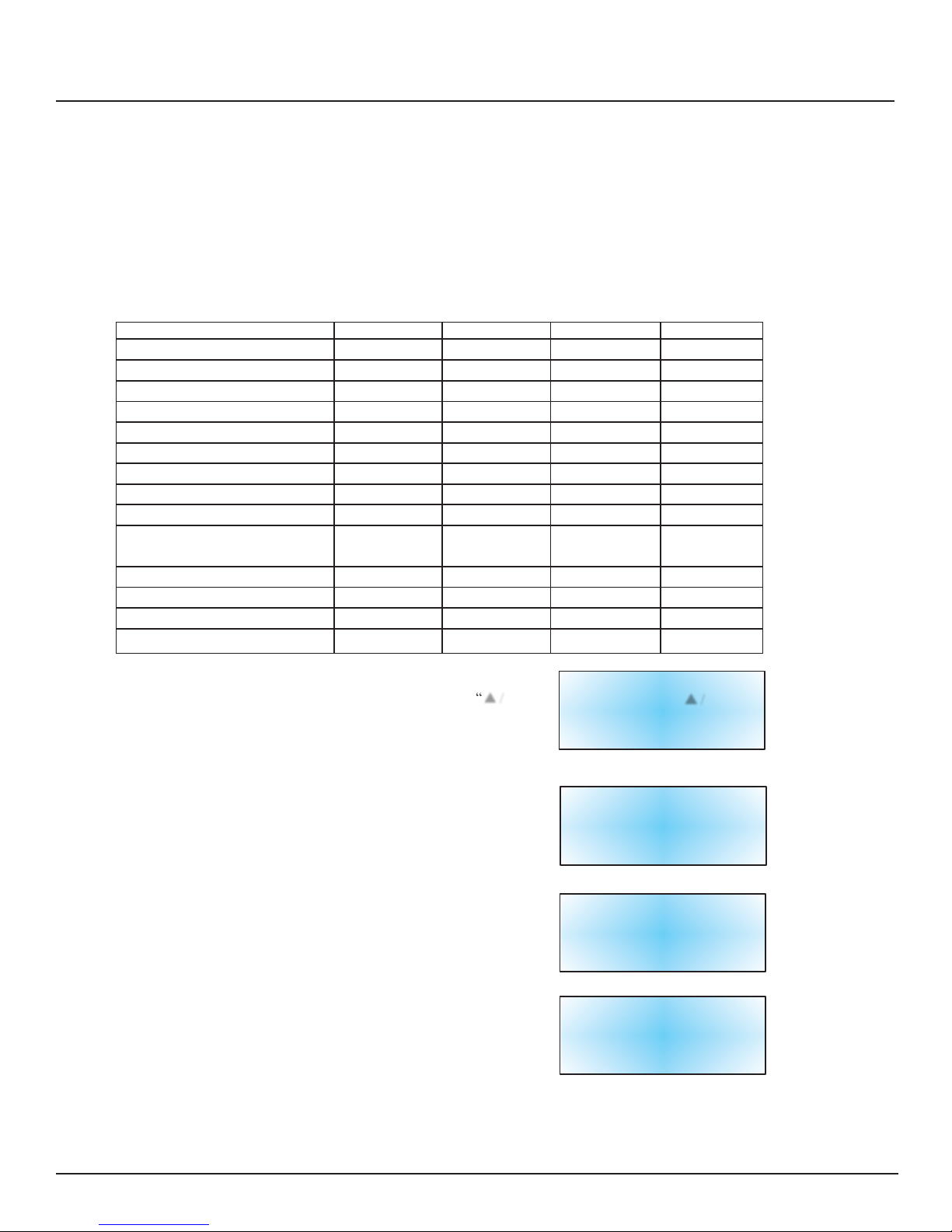
=#"
MVE$Automation$Series$Ha n dbuch$mit$Kurzanleitung"
!
!
!
Impostazioni$di$sicurezza$e$password"
Il TEC 3000 può memorizzare fino a 10 password diverse. Si può assegnare un distinto livello di sicurezza a ciascuna password, da Livello 1 a Livello 4. La tabella 3 mostrata in seguito elenca le impostazioni modificabili con ciascun
livello di sicurezza. Per modificare una password è necessario un livello di sicurezza 4. La password predefinita (o
"Globale") per il TEC 3000 è "3456". Tutti i parametri possono essere modificati usando questa password. Registrare
tutte le password e le impostazioni di sicurezza e conservarle in un luogo sicuro. NOTA: MVE consiglia di cambiare
la password globale, poiché essa è comune a tutte le unità. In caso si sia dimenticata la password globale, contattare il
servizio clienti MVE per maggiori dettagli sulle modalità di resettaggio delle password.
!
D/?,33/"=S""G!H,33!"'!"1!)(%,ZZ/","',.!-!Z!&-!"
!
RYXk+MX;"
G+d;GGM" #"
G+d;GGM" 8"
G+d;GGM" ="
G+d;GGM" A"
BHH!&"^!,:2!:,-*&"
n"n"n"
n"
B%%,1*&"%!,:2!:,-* & "
n"n"n"
n"
B33/%:,"1!3,-Z!&1&"
n"n"n"
n"
6/:?!/"(-!*t"'!123/4"
n"n"n"
n"
+:2&1*/Z!&-!"*,:2,%/*(%/"
!
n"n"n"
+:2&1*/Z!&-!"3!H,33&"
!
n"n"n"
M%/50/*/"!n"n"n"
E&-',"'!")/3!?%/*(%/"
!
n"n"n"
_&'!.!)/"3!-@(/@@!"
!
n"n"n"
+:2&1*/Z!&-!"'!"',%!H/Z!&-,"
',!"@/1"/'"/3*/"*,:2,%/*(%/"
!
!n"!n"!
n"
+:2&1*/Z!&-!"M RBR"
!
!
n"
n"
+:2&1*/Z!&-!"'!")&:(-!)/Z!&-,"
!
!
n"
n"
$%&@%/::/Z!&-,"
!
!
n"
n"
+:2&1*/Z!&-!"2/11>&%'"
!!!
n"
!
1. PREMERE “SETUP”
Il controller richiederà una password. Utilizzare i tasti “▲ /
▼”
per scorrere fino al numero corretto. Se si sta
impostando la password per la prima volta, utilizzare la
password predefinita “3456”. Premere “Enter” per spostare
il cursore alla posizione successiva della password.
!
2. PREMERE “ENTER”
Il display visualizzerà il messaggio “menu Temperatura”.
!
!
!
!
!
3. PREMERE “SETUP”
finché il display non visualizza “menu Password”.
!
!
!
!
4. PREMERE “ENTER”
Il display visualizzerà “Premere Enter per accedere al menu
Modifica password globale o premere Setup per passare al
menu successivo”.
Livello utente più
alto
E’
necessario utilizzare
▲ / ▼ per
inserire
la password
0000
!
!
!
Premere Enter
per
accedere
ai
menu
Temperatura
o
premere Setup
per
passare
al
menu
successivo
!
!
Premere Enter
per
accedere
ai
menu
Password
o
premere Setup
per
passare
al
menu
successivo
!
!
Premere Enter
per
accedere
al menu
Modifica password
globale
o
premere
Setup
per
passare
al
menu
successivo
!
!
NOTA: L’impostazione predefinita per la password “Globale” è “3456”. La password “Globale” può essere utilizzata
per cambiare TUTTE le impostazioni del TEC 3000.
Page 33

=8"
MVE$Automation$Series$Ha n dbuch$mit$Kurzanleitung"
!
!
!
!
Impostazioni$di$sicurezza$e$password
"
!
5. PREMERE “SETUP”
per scorrere fino al numero di password desiderato.
!
6. PREMERE “ENTER”
per selezionare il numero di password desiderato.
!
!
7. PREMERE “ ▲” o “ ▼”
per scorrere fino al numero corretto. Premere “Enter” per
spostare il cursore alla posizione successiva della password.
!
!
!
!
8. PREMERE “ENTER”
dopo aver selezionato la password desiderata. Il display
visualizzerà ora la scritta “Password livello X”. Usare i tasti
“▲ /
▼”
per regolare il livello di sicurezza.
!
!
!
!
9. PREMERE “ENTER”
Il display visualizzerà il messaggio “Confermare nuova
password?”. Usare i tasti “▲ /
▼”
per selezionare “SÌ” o
“NO”. Selezionando “SÌ” vengono salvate la nuova
password e le nuove impostazioni di sicurezza. Selezionando
“NO” si annullano tutti i cambiamenti.
!
!
!
10. PREMERE “ENTER”
per salvare le impostazioni.
Password
1
Utilizzare
▲ / ▼ per regolare
Premere Enter
per passare
ad
XXXX
!
!
!
Password livello
X
Utilizzare / ▼
p
er
regolare
Premere Enter
per passare
al
livello
X successivo
!
!
!
!
!
Confermare
nuova
password?
NO
Utilizzare / ▼
p
er
regolare
!
!
!
!
A questo punto, la password selezionata e il livello di sicurezza sono stati impostati e salvati. Seguire i passaggi dal 7
all’11 per impostare password e livelli di sicurezza aggiuntivi, o premere ripetutamente “Escape” per tornare alla
schermata del display. Dopo 5 minuti di inattività, il controller ritornerà automaticamente alla modalità di
visualizzazione “monitor”. Usare la tabella 4 per registrare le password per una futura consultazione.
Page 34

=="
MVE$Automation$Series$Ha n dbuch$mit$Kurzanleitung"
!
!
!
!
!
Allarmi$e$descrizioni
"
!
!
D/?,33/"AS"B33/%:!","',1)%!Z!&-!"
!
Visualizzazione allarme
Descrizione
Temp A alta
La temperatura della sonda A è al di sopra della soglia Temperatura alta definita
dall’utente.
Temp B alta
La temperatura della sonda B è al disopra della soglia Temperatura alta definita
dall’utente.
Temp A bassa
La temperatura della sonda A è al di sotto della soglia Temperatura bassa
definita dall’utente.
Temp B bassa
La temperatura della sonda B è al di sotto della soglia Temperatura bassa
definita dall’utente.
Livello alto
Il livello dell’LN2 all’interno del freezer è al di sopra della soglia Livello alto
definita dall’utente.
Livello basso
Il livello dell’LN2 all’interno del freezer è al di sotto della soglia Livello basso
definita dall’utente.
Avviso utilizzo
Il consumo di LN2 è raddoppiato (vedere il manuale tecnico di riferimento TEC
3000 per maggiori dettagli).
Allarme utilizzo
Il consumo di LN2 è aumentato di un fattore equivalente a 5 (vedere il manuale
tecnico di riferimento TEC 3000 per maggiori dettagli).
Tempo di riempimento
Il tempo richiesto per completare un ciclo di riempimento eccede
l’impostazione Tempo di riempimento impostata dall’utente.
Tempo di derivazione
Il tempo richiesto per completare un ciclo di derivazione eccede l’impostazione
Tempo di derivazione impostata dall’utente.
Calibratura Temp A
La temperatura della sonda A è minore dello zero assoluto.
Calibratura Temp B
La temperatura della sonda B è minore dello zero assoluto.
Calibratura derivazione
La temperatura della sonda di derivazione è minore dello zero assoluto.
Batteria scarica
Il voltaggio delle batterie di backup è sceso sotto i 21 Volt.
Guasto energetico
L’alimentazione primaria è stata scollegata per almeno 60 minuti.
Coperchio aperto
Il coperchio del freezer è rimasto aperto per un periodo superiore al tempo
specificato dall’utente.
Comunicazione persa
Il controller ha perso la comunicazione con il display.
!
!
In caso di allarme contattare il distributore autorizzato MVE di
zona o l’assistenza clienti/tecnica.
!
E,%H!Z!&")3!,-*!5*,)-! )&S
"
!
YEBS"!;(%&2/S"
D,3,.&-&S"
#JNPPJAN8J8AK="
D,3,.&-&S" bAA"VPW"#=AA"AP="#PP"
R/TS"
#JNNNJO=8J8AK="
R/TS" bAA"VPW"#=AA"A8O"88A"
!
B1!/S"
D,3,.&-&S""bI#"8OK"AOA==="
R/TS" bI#"8OK"AOAIII"
Page 35

=A"
MVE$Automation$Series$Guía$de$referencia$rápida
"
!
!
!
!
!
!
!
Español$ Índice
"
!
!
+',-*!.!)/)!x-"',3"2%&'()*&"
$/-*/33/5*/?3,%&"',")&-*%&3" 7"7"7"7"7"7"7"7"7"7"7"7"7"7"7"7"7"7"7"7"7"7"7"7"7"7"7"7"7"7"7"7"7"7"7"7"7"7"7"7"7"7"7"7"7"7"=F"
D/ ?3,%&"!-.,%!&%56 & - ,T!&-,1",3u)*%!)/15.y1!)/1""7"7"7"7"7"7"7"7"7"7"7"7"7"7"7"7"7"7"7"7"7"7"7"7"7"7"7"7"7"7"7"=I"
6&-,T!&-,1"',"*(?,%y/1 "',"3& 1 "',2x1!*&1"0,>/%"" 7"7"7"7"7"7"7"7"7"7"7"7"7"7"7"7"7"7"7"7"7"7"7"7"7"7"7"7"7"7"=K"
6x:&")&-.!@(%/%"3/"/3/%:/"',"*,:2 , %/*(%/" 7"7"7"7"7"7"7"7"7"7"7"7"7"7"7"7"7"7"7"7"7"7"7"7"7"7"7"7"7"7"7"7"7"7"7"=N"
6x:&"/C(1*/%",3"-!H,3"4")&-.!@(%/%",3"-!H,3"',"/3/%:/" 7"7"7"7"7"7"7"7"7"7"7"7"7"7"7"7"7"7"7"7"7"7"7"7"=O"J"AP"
6&-.!@(%/)!x-"',"3/"/3/%:/"',"-!H,3"/3*&"
6&-.!@(%/)!x-"',"-!H,3"/3*&"
6&-.!@(%/)!x-"',"-!H,3"?/C&"
6&-.!@(%/)!x-"',"3/"/3/%:/"',"-!H,3"?/C&"
6x:&"/C(1*/%"3/"2/-*/33/"4")&-.!@(%/%"3/"1/3!'/"77"7"7"7"7"7"7"7"7"7"7"7"7"7"7"7"7"7"7"7"7"7"7"7"7"7"7"7"7"7"7"7"A#"
6/3!?%/)!x-"',"3&1"1,-1&%,1"',"*,:2,%/*(%/" 7"7"7"7"7"7"7"7"7"7"7"7"7"7"7"7"7"7"7"7"7"7"7"7"7"7"7"7"7"7"7"7"7"7"A#"
6&-*%/1,z/"4")&-.!@(%/)!x-"',"1,@(%!'/'"" 7"7"7"7"7"7"7"7"7"7"7"7"7"7"7"7"7"7"7"7"7"7"7"7"7"7"7"7"7"7"7"7"A8"J"A="
B3/%:/1"4"',.!-!)!&-,1"7"7"7"7"7"7"7"7"7"7"7"7"7"7"7"7"7"7"7"7"7"7"7"7"7"7"7"7"7"7"7"7"7"7"7"7"7"7"7"7"7"7"7"7"7"7"7"7"7"7"7"AA"
+-.&%:/)!x-"',")&-*/)*&"7"7"7"7"7"7"7"7"7"7"7"7"7"7"7"7"7"7"7"7"7"7"7"7"7"7"7"7"7"7"7"7"7"7"7"7"7"7"7"7"7"7"7"7"7"7"7"7"7"7"AA
"
!
NOTA: Todos los modelos MVE son dispositivos médicos Clase 1, con suministro externo de
energía y operación continua. No son adecuados para usarse con anestésicos inflamables. Este
equipo ha sido probado y cumple los límites establecidos en la norma IEC 601-1-2 para dispositivos
médicos: [o EN 60601-1-1-2:2001 o Directiva de Dispositivos Médicos 93/42/EEC].
!
!
!
NOTA: Los congeladores de nitrógeno líquido MVE deben ser instalados por un distribuidor
MVE según el Manual Técnico del TEC 3000, N/P 13289499
Page 36

=F"
MVE$Automation$Series$Guía$de$referencia$rápida
"
!
!
!
!
!
!
!
!
3
4
!
1
5
6
!
!
2
7
8
!
!
9 10
!
!
!
!
D/?3/"#S"!',-*!.!)/)!x-"',3"*/?3,%&"',3/-*,%&
"
!
!
!
#" D/?3,%&"',3/-*,%&" ;3"*/?3,%&"',3/-*,%&",1"3/"!-*,%./1,"',"(1(/%!&"',3"D;6"=PPP7"
D&'/1"3/1"2/-*/33/1"4")&-*%&3,1"1,",-)(,-*%/-",-",3"*/?3,%&"',3/-*,%&"
8" $/-*/33/" Y-/"2/-*/33/"',")%!1*/3"3yU(!'&"VG60W"' ,"A"T"8P":(,1*%/",3"H/3&%"',"*&'/1"3/1"
)&-'!)!&-,1"/)*(/3,1]"!-)3(4,-'&"*,:2,%/*(%/"4"-!H,3"',3"-!*%x@,-&"3yU(!'&7"G/"2/-*/33/"
*/:?!u-":(,1*%/",3",1*/'&"',"/3/%:/",-")(%1&7"
=" E*/%*"R!33"{+-!)!/%"33,-/' & |" " E,"(1/"2/%/"33,-/%":/-(/3:,-*,",3")&-@,3/'&%")&-"-!*%x@,-&"3yU(!'&7";1*,"?&*x-"
*/:?!u-"2(,',"2%,1 !&- / %1 , "2 / %/",3!:!-/%"3/"[-,?3!-/\"',3"}%,/"',"/3:/),-/:!,-*&"
2/%/"/(:,-*/%"3/"H!1!?!3!'/'"
A" E*&2"R!33" E,"(1/"2/%/"',*,-,%":/-(/3:,-*,",3")!)3&"',"33,-/'&7"0,12(u1"',"2%,1!&-/%",1*,"
{0,*,-,%"33,-/'&|" ?&*x-]"3/"(-!'/'"-&"%,!-!)!/%}",3"33,-/'&"</1*/"U(,"3/")&-.!@(%/)!x-"',"-!H,3"?/C&"1,"
</4/"/3)/-Z/'&"&"1,"2%,1!&-,",3"?&*x-"[EDB^D"R+GG\7"
F" E,*(2" E,"(1/"2/%/"/C(1*/%",3"H/3&%"',"*&'/1"3/1".(-)!&-,1"U(,"2(,',":&'!.!)/%",3"(1(/%!&]"
!-)3(4,-'&"-!H,3]"/3/%:/1"',"-!H,3]"/3/%:/1"',"*,:2,%/*(%/]")&-*%/1,z/1]",*)7"
I" B3/%:"_(*," E,"(1/"2/%/"1!3,-)!/%"(-/"/3/%:/"/('!?3,7"D/:?!u-"1,"(1/"2/%/"%,1*/?3,),%"3/"/3/%:/"
{E!3,-)!/%"/3/%:/|" ',"?3&U(,&"(-/"H,Z"U(,"1,"</")&%%,@!'&",3",1*/'&"',"/3/%:/7"
K" R3,)</"</)!/"/%%!?/" E,"(1/"2/%/"!-)%,:,-*/%",3"H/3&%"'(%/-*,",3":&'&"',"[6&-.!@(%/)!x-\7"$%,1!&-,"(-/"
H,Z"2/%/"'!1:!-(!%",-"!-)%,:,-*&17"_/-*,-@/",3"?&*x-"2%,1!&-/'&"2/%/"/H/-Z/%"
%}2!'/:,-*,"2&%"3&1"H/3&%,17"D/:?!u-"1,"2(,',"(1/%"2/%/")/:?!/%",-*%,"[E~5XM\"&"
[MX5MRR\"{;X6;X0;^5B$BQB^|7"
N" R3,)</"</)!/"/?/C&" E,"(1/"2/%/"'!1:!-(!%",3"H/3&%"'(%/-*,",3":&'&"',"[6&-.!@(%/)!x-\7"$%,1!&-,"(-/"H,Z"
2/%/"'!1:!-(!%",-"!-)%,:,-*&17"_/-*,-@/",3"?&*x-"2%,1!&-/'&"2/%/")/:?!/%"
%}2!'/:,-*,"2&%"3&1"H/3&%,17" D/:?!u-"1,"2(,',"(1/%"2/%/")/:?!/%",-*%,"[E~5XM\"&"
[MX5MRR\"{;X6;X0;^5B$BQB^|7"
O" ;E6"{E/3!%|" E,"(1/"2/%/"1/3!%"',")(/3U(!,%":,-•"&".(-)!x-7"
#P"";-*,%"{+-*%&|" E,"(1/"2/%/"1,3,))!&-/%"4",'!*/%")(/3U(!,%":,-•"&"2/%/"@(/%'/%")(/3U(!,%"
)&-.!@(%/)!x-"',3"(1(/%!&7"
Page 37

=I"
MVE$Automation$Series$Guía$de$referencia$rápida
"
!
!
!
!
!
!
!
!
O"
#"
!
!
!
!
!
8"
A"
F
"
=
"
#P
"
!
!
!
I"
K" N"
!
!
!
!
!
D/?3/"8S"!',-*!.!)/)!x-"',3"*/?3,%&"!-.,%!&%
"
!
!
!
#" D,:2"B" 6&-,T!x-"2/%/",3"1,-1&%"',"*,:2,%/*(%/"B7"
8" D,:2"9" 6&-,T!x-"2/%/",3"1,-1&%"',"*,:2,%/*(%/"97"
=" 6&-,T!&-" 6&-,T!x-"2/%/",-*%/'/"',",-,%@y/7"
',",-,%@y/"
A" 6M_"#" 6&-,T!x-"2/%/"3/"!-*,%./1,"',")&:(-!)/)!x-"^EJANF7"
F" 6M_"8" 6&-,T!x-"%,'(-'/-*,"2/%/"3/"!-*,%./1,"',")&:(-!)/)!x-"^EJANF7"
I" _/-(/3"R!33" ;3"?&*x-"',"33,-/'&":/-(/3"1,"(1/"2/%/"/-(3/%",3"1&.*>/%,"D;6"=PPP"4"33,-/%"
{G3,-/'&":/-(/3|" :/-(/3:,-*,",3")&-@,3/'&%7"
K" 6&-,T!&-,1" ;1*/1")&-,T!&-,1":&-!*&%,/-"3/1"/3/%:/1"',"D,:2,%/*(%/"B"/3*/]"X!H,3"?/C&]"9/*,%y/"
'!1)%,*/1" ?/C/"4"1(:!-!1*%&"GX8"V-!H,3"',"-!*%x@,-&"3yU(!'&W7"$(,',-",1*/%")&-,)*/'/1"/")(/3U(!,%"
',"/3/%:/" 1!1*,:/"',"/3/%:/"U(,"(1,")&-*/)*&1"X&%:/3:,-*,"/?!,%*&1"VXMW7"
N" 6&-,T!&-,1" ;1*/1")&-,T!&-,1":&-!*&%,/-"DM0BE"3/1"/3/%:/17"$(,',-",1*/%")&-,)*/'/1"/"
@3&?/3,1" )(/3U(!,%"1!1*,:/"',"/3/%:/"U(,"(1,")&-*/)*&1"X&%:/3:,-*,"/?!,%*&1"VXM W"& "
',"/3/%:/" X&%:/3:,-*,"),%%/'&1"VX6W7"
O" B%-u1" 6&-,T!x-"2/%/",3"/%-u1"',")/?3,/'&"2%!-)!2/37"D&'/1"3/1")&-,T!&-,1"',"3/1"
2%!-)!2/3" H}3H(3/1"1&3,-&!',1]"!-*,%%(2*&%"',"3/"*/2/]"1,-1&%"',"',%!H/)!x-]",*)7"1,",-)(,-*%/-"
',")&-,T!x-" /U(y7"
#P""6&-,T!x-" 6&-,T!&-,1"2/%/",3"1!1*,:/"',"',*,))!x-"',"-!H,37"G&1"-!H,3,1"1,"',*,)*/-"2&%":,'!&"
',"-!H,3" ',"(-"1,-1&%"',"2%,1!x-"'!.,%,-)!/3]"U(,"1,",-)(,-*%/",-",3"!-*,%!&%"',3"D;6"=PPP7";3"
*(?&"',"3/"3y-,/"',"',*, )) !x - "' , "- !H,3,1"',3")&-@,3/'&%"1,")&-,)*/"/U(y7"G/")&-,T!x-",1"
(-/",12!@/"',":/-@(,%/"',"#5N\"V=78"::W"',"'!}:,*%&",T*,%!&%7"
Page 38

=K"
Conexiones$de$tuberías$de$los$depósitos$Dewar"
Conecte una línea de transferencia (incluida con el congelador) de un depósito de suministro de LN2 (nitrógeno líquido) a la
conexión de llenado de la parte trasera del congelador. La presión óptima del depósito de suministro es de 22 a 35 lb/pulg2
(1,5 a 2,4 bares). Aunque el conjunto de tuberías tiene un dispositivo de alivio de presión de 50 lb/pulg2 (3,45 bares), se
recomienda someter el depósito a una presión menor que 35 lb/pulg2 (2,4 bares) para reducir el índice de vaporización
instantánea de LN2 durante el llenado y prolongar al máximo la duración de la válvula criogénica. La línea de suministro
puede aislarse para reducir al mínimo las pérdidas de transferencia de LN2. Después de acoplar fijamente la manguera de
transferencia al congelador y al depósito de suministro, asegúrese de que no haya fugas en ninguna conexión abriendo la
válvula del depósito de suministro de LN2 y aplicando una solución de agua jabonosa a cada junta. No debe observar la formación de burbujas en ninguna junta. Limpie el exceso de agua jabonosa cuando termine. Antes de desconectar la manguera
de transferencia, asegúrese de que la válvula del depósito de suministro de LN2 esté cerrada. Afloje lenta y cuidadosamente
la conexión de la manguera de transferencia para aliviar la presión restante de la línea antes de desconectar la manguera.
G~X;B"0;"D^BXER;^;X6+B
"
X+D^€Q;XM"G~rY+0M
"
;XD^B0B"0;"
GX8"
!!!!!CORDÓN!DE!!
!!!!ALIMENTACIÓN!
DEWAR!DE!ALMACENAMIENTO! ! ! !!!!!!!!!!DEWAR!DE!SUMINISTRO!
Page 39

=N"
MVE$Automation$Series$Guía$de$referencia$rápida"
!
!
!
!
!
!
!
La siguiente sección describe la manera de ajustar la configuración de la alarma de temperatura. En cualquier momento
del siguiente procedimiento, el usuario puede salir del nivel presionando el botón “Escape” varias veces, hasta que la
pantalla regrese al modo de “monitor”. Después de 30 segundos de inactividad, el controlador regresará
automáticamente al modo de “monitor”.
!
NOTA: se requiere un nivel de seguridad 2 o mayor para ajustar la configuración de temperatura (vea más detalles en
la sección “Configuración de contraseña y seguridad”).
Para salir de la pantalla de menú y volver al menú anterior, presione la tecla “ESC”.
!
!
1. PRESIONE “SETUP”
El controlador le indicará que escriba una contraseña. Use las
teclas “▲ / ▼” para ir hasta el número adecuado. Presione
“Enter” para mover el cursor a la siguiente posición de la
contraseña.
!
2. PRESIONE “ENTER”
La pantalla mostrará el mensaje “Menús de temperatura” .
!
!
!
!
3. PRESIONE “ENTER”
La pantalla mostrará el mensaje “Menú de temperatura A” .
NOTA: para ajustar la configuración de la Temp B, presione
“Setup” en lugar de “Enter”.
!
!
4. PRESIONE “ENTER”
La pantalla mostrará el mensaje “Temp A Activado”.
NOTA: el sensor A puede desactivarse ahora presionando las
“teclas▲ /
▼”.
Presione “Enter” para guardar la configuración.
!
5. PRESIONE “SETUP”
Hasta que la pantalla muestre el mensaje “Alarma de
temperatura A alta”. Use las teclas “▲ / ▼” para ajustar la
temperatura. Mantenga presionado cualquiera de estos botones
para avanzar rápidamente. Presione “Enter” para guardar la
configuración.
!
6. PRESIONE “SETUP”
La pantalla mostrará el mensaje “Alarma de temperatura A
baja”. Use las teclas “▲ / ▼” para ajustar la temperatura.
Mantenga presionado cualquiera de estos botones para avanzar
rápidamente. Presione “Enter” para guardar la configuración
Nivel
de
usuario
alto
Uso necesario
▲ / ▼ para
ingresar
contraseña
0000
!
!
Presione Enter
para
Menús de temperatura
o
presione Setup
para
el
siguiente
menú
!
!
Presione Enter
para
Menú
de
temperatura
A
o
presione Setup
para
el
siguiente
menú
!
!
Temp
A
Activado
Use
▲ / ▼ para
ajustar
Presione Enter para
guardar
!
!
!
Alarma de temperatura A
alta
Use
▲ / ▼ para
ajustar
Presione Enter para
guardar
-110.0
°C
!
!
!
!
Alarma
de
temperatura
A baja
Use
▲ / ▼ para
ajustar
Presione Enter para
guardar
-200.0
°C
!
!
!
Después de haber concluido todos los ajustes, espere 30 segundos y TEC 3000 volverá a la pantalla principal indicando
que la nueva configuración se encuentra vigente.
Page 40

=O"
MVE$Automation$Series$Guía$de$referencia$rápida"
!
!
!
!
!
La siguiente sección describe la manera de ajustar los niveles de nitrógeno líquido y las alarmas de nivel alto/bajo.
NOTA: Se requiere un nivel de seguridad 2 o mayor para ajustar la configuración de Nivel y Alarma de nivel (vea más detalles
en la sección “Configuración de contraseña y seguridad”).
!
NOTA: para salir de la pantalla del menú y volver al menú anterior, presione la tecla “ESC”.
!
CONFIGURACIÓN DE NIVEL DE ALARMA ALTO:
!
1. PRESIONE “SETUP”
El controlador le indicará que escriba una contraseña. Use las
teclas “▲ /
▼”
para ir hasta el número adecuado. Presione
“Enter” para mover el cursor a la siguiente posición de la
contraseña.
!
!
!
2. PRESIONE “SETUP”
Hasta que la pantalla muestre el mensaje “Menús de nivel de
líquido”.
!
!
3. PRESIONE “ENTER”
La pantalla mostrará el mensaje “Alarma de nivel alto”. Use las
teclas “▲ /
▼”
para ajustar. Presione “Enter” para guardar la
configuración.
NOTA: no se puede hacer ningún ajuste de menos de 0.5
pulgadas (14 mm) entre cada uno.
!
Nivel
de
usuario
alto
Uso necesario ▲ / ▼ para
ingresar
contraseña
0000
!
!
Presione Enter
para
Menús de nivel de líquido
o
presione Setup
para
el
siguiente
menú
!
!
!
Alarma
de
nivel
alto
8.0 pulgadas
Use ▲ / ▼ para
ajustar
Presione Enter para
guardar
!
Después de haber concluido todos los ajustes, espere 30 segundos y TEC 3000 volverá a la pantalla principal indicando
que la nueva configuración se encuentra vigente.
!
CONFIGURACIÓN DE NIVEL ALTO:
!
1. PRESIONE “SETUP”
El controlador le indicará que escriba una contraseña. Use las
teclas “▲ /
▼”
para ir hasta el número adecuado. Presione
“Enter” para mover el cursor hasta la siguiente posición de la
contraseña.
!
2. PRESIONE “SETUP”
Hasta que la pantalla muestre el mensaje “Menús de nivel de
líquido”.
!
!
3. PRESIONE “ENTER”
La pantalla mostrará el mensaje “Alarma de nivel alto”.
!
!
!
4. PRESIONE “SETUP”
La pantalla mostrará el mensaje “Punto de ajuste de nivel
alto”. Use las teclas “▲ /
▼”
para ajustar. Presione “Enter”
para guardar la configuración.
Nivel
de
usuario
alto
Uso necesario ▲ / ▼ para
ingresar
contraseña
0000
!
Presione Enter
para
Menús
de
nivel
de líquido
o
presione Setup
para
el
siguiente
menú
!
!
Alarma
de
nivel
alto
8.0 pulgadas
Use ▲ / ▼ para
ajustar
Presione Enter para
guardar
!
!
Punto
de
ajuste
de
nivel
alto
7.0
pulgadas
(in)
Use ▲ / ▼ para
ajustar
Presione Enter para
guardar
!
Después de haber concluido todos los ajustes, espere 30 segundos y TEC 3000 volverá a la pantalla principal indicando
que la nueva configuración se encuentra vigente.
Page 41

AP"
MVE$Automation$Series$Guía$de$referencia$rápida"
!
!
!
!
Cómo$ajustar$la$configuración$de$nivel$y$$nivel$de$alarma"
NOTA: para salir de la pantalla del menú y volver al menú anterior, presione la tecla “ESC”.
!
CONFIGURACIÓN DE NIVEL BAJO
!
1. PRESIONE “SETUP”
El controlador le indicará que escriba una contraseña. Use las
teclas “▲ /
▼”
para ir hasta el número adecuado. Presione
“Enter” para mover el cursor hasta la siguiente posición de la
contraseña.
!
2. PRESIONE “SETUP”
Hasta que la pantalla muestre el mensaje “Menús de nivel de
líquido”.
!
!
3. PRESIONE “ENTER”
La pantalla mostrará el mensaje “Alarma de nivel alto”.
!
!
!
!
4. PRESIONE “SETUP”
hasta que la pantalla muestre el mensaje “Punto de ajuste de
nivel bajo”. Use las teclas “▲ /
▼”
para ajustar la
configuración. Presione “Enter” para guardar la configuración.
!
Nivel
de
usuario
alto
Uso necesario ▲ / ▼ para
ingresar
contraseña
0000
!
!
Presione Enter
para
Menús
de
nivel
de líquido
o
presione Setup
para
el
siguiente
menú
!
!
Alarma
de
nivel
alto
8.0 pulgadas
Use ▲ / ▼ para
ajustar
Presione Enter para
guardar
!
!
Punto
de
ajuste
de
nivel
bajo
5.0
pulgadas
Use ▲ / ▼ para
ajustar
Presione Enter para
guardar
!
Después de haber concluido todos los ajustes, espere 30 segundos y TEC 3000 volverá a la pantalla principal indicando
que la nueva configuración se encuentra vigente.
!
!
CONFIGURACIÓN DE NIVEL DE ALARMA:
!
1. PRESIONE “SETUP”
El controlador le indicará que escriba una contraseña. Use las
teclas “▲ /
▼”
para ir hasta el número adecuado. Presione
“Enter” para mover el cursor hasta la siguiente posición de la
contraseña.
!
2. PRESIONE “SETUP”
Hasta que la pantalla muestre el mensaje “Menús de nivel de
líquido”.
!
!
3. PRESIONE “ENTER”
La pantalla mostrará el mensaje “Alarma de nivel alto”.
!
!
!
!
!
4. PRESIONE “SETUP”
hasta que la pantalla muestre el mensaje “Alarma de nivel
bajo”. Use las teclas “▲ /
▼”
para ajustar. Presione “Enter”
para guardar la configuración.
!
Nivel
de
usuario
alto
Uso necesario ▲ / ▼ para
ingresar
contraseña
0000
!
!
Presione Enter
para
Menús
de
nivel
de líquido
o
presione Setup
para
el
siguiente
menú
!
!
Alarma
de
nivel
alto
8.0 pulgadas
Use ▲ / ▼ para
ajustar
Presione Enter para
guardar
!
!
!
Alarma
de
nivel
bajo
4.0 pulgadas
Use ▲ / ▼ para
ajustar
Presione Enter para
guardar
Page 42

A#"
MVE$Automation$Series$Guía$de$referencia$rápida"
!
!
!
!
Ajuste$de$las$configuraciones$de$visualización$y$salida
"
!
Las unidades de medición mostradas por el TEC 3000 pueden ajustarse según las necesidades del usuario. La medida
de temperatura se puede mostrar en grados Kelvin (ºK), grados Celsius (ºC) o grados Fahrenheit (ºF). La cantidad de
nitrógeno líquido dentro del congelador se puede mostrar en pulgadas (in). La pantalla también puede mostrar la
cantidad de nitrógeno líquido que ha consumido el congelador (consumo de líquido).
!
NOTA: se requiere un nivel de seguridad 1 para ajustar la configuración de visualización y salida (vea más detalles
en la sección “Configuración de contraseña y seguridad”).
!
1. PRESIONE “SETUP”
El controlador le indicará que escriba una contraseña. Use las
teclas “▲ /
▼”
para ir hasta el número adecuado. Presione
“Enter” para mover el cursor hasta la siguiente posición de la
contraseña.
!
!
2. PRESIONE “SETUP”
Hasta que la pantalla muestre el mensaje “Visualización y
salida”.
!
!
3. PRESIONE “ENTER”
La pantalla mostrará el mensaje “Unidades de temperatura”.
Use las teclas “▲ /
▼”
para cambiar entre ºC (Celsius), °F
(Fahrenheit) o °K (Kelvin). Presione “Enter” para guardar la
configuración.
!
4. PRESIONE “SETUP”
La pantalla mostrará el mensaje “Unidades de nivel”. Use las
teclas “▲ /
▼”
para cambiar entre “in” (pulgadas) o “mm”
(milímetros). Presione “Enter” para guardar la configuración.
!
5. PRESIONE “SETUP”
La pantalla mostrará el mensaje “Mostrar consumo de
líquido”. Use las teclas “▲ /
▼”
para seleccionar “SÍ” o
“NO” Presione “Enter” para guardar la configuración.
!
Nivel
de
usuario
alto
Uso necesario
▲ / ▼ para
ingresar
contraseña
0000
!
!
Presione Enter
para
Visualización
y salida
o
presione Setup
para
el
siguiente
menú
!
!
!
Unidades
de temperatura
°C
Use
▲ / ▼ para
ajustar
Presione Enter para
guardar
!
!
!
Unidades
de nivel
Pulgadas
(In)
Use
▲ / ▼ para
ajustar
Presione Enter para
guardar
!
!
!
!
!
Después de haber concluido todos los ajustes, espere 30 segundos y TEC 3000 volverá a la pantalla principal indicando
que la nueva configuración se encuentra vigente.
!
!
!
Calibración$de$sensores$de$temperatura"
!
Cada uno de los sensores de temperatura (A y B) que se usan con el TEC 3000 han sido calibrados en fábrica usando
el método de “Rango de temperatura baja”. Este método de calibración proporciona un nivel de exactitud de +/-1.8
°F (+/-1 °C) cuando se opera dentro del rango de altitud de 1000 pies a 1500 pies. (305 m a 457 m). No debe ser
necesario realizar otro tipo de calibración, a menos que lo desee el usuario final. Consulte el Manual técnico TEC
3000 para información sobre los métodos y procedimientos de calibración.
Page 43

A8"
MVE$Automation$Series$Guía$de$referencia$rápida"
!
!
!
Configuración$de$contraseñas$y$seguridad"
El TEC 3000 puede guardar hasta 10 contraseñas diferentes. A cada contraseña se le puede asignar su propio nivel de
seguridad, desde el Nivel 1 hasta el Nivel 4. La tabla 3 muestra qué configuraciones se pueden cambiar con cada nivel de
seguridad. Para ajustar cualquier contraseña se necesita un nivel de seguridad 4. La contraseña predeterminada (o “Global”)
para TEC 3000 es “3456”. Todos los parámetros se pueden ajustar usando esta contraseña. Registre todas las contraseñas
y configuraciones de seguridad y guárdelas en un lugar seguro. NOTA: MVE recomienda cambiar la contraseña global, ya
que es igual para todas las unidades. Si olvida la contraseña global, comuníquese con el departamento de Servicio al Cliente
de MVE para obtener detalles sobre cómo restablecer las contraseñas.
!
D/?3/"=S"X!H,3,1"',"1,@(%!'/'"4"',.!-!)!&-,1"
!
RYX6+€X"
X+d;G"#"
X+d;G"8"
X+d;G"="
X+d;G"A"
R!33"E*/%*"{+-!)!/ %"33,-/'&|"
n"n"n"
n"
R!33"E*&2"{0,*,-, %"33,-/'&|"
n"n"n"
n"
B3/%:"_(*,"{E!3,-)!/%"/3/%:/|"
n"n"n"
n"
6/:?!/%"(-!'/',1"
n"n"n"
n"
6&-.!@(%/)!x-"',"*,:2,%/*(%/"
!
n"n"n"
6&-.!@(%/)!x-"',"-!H,3"
!
n"n"n"
L&%/5R,)</"
!
n"n"n"
E,-1&%,1"',")/3!?%/)!x-"
!
n"n"n"
6/:?!&"',"!'!&:/"
!
n"n"n"
6&-.!@(%/)!&-,1"',"',%!H/)!x-"
',"@/1,1")/3!,-*,1"
!
!n"!n"!
n"
6&-.!@(%/)!&-,1"MRBR"
!
!
n"
n"
6&-.!@(%/)!&-,1"',")&:(-!)/)!x-"
!
!
n"
n"
$%&@%/:/)!x-"
!
!
n"
n"
6&-.!@(%/)!x-"',")&-*%/1,z/1"
!!!
n"
!
1. PRESIONE “SETUP”
El controlador le indicará que escriba una contraseña. Use las
teclas “▲ / ▼ ” para ir hasta el número adecuado. Cuando
configure las contraseñas por primera vez, use la contraseña
predeterminada “3456”. Presione “Enter” para mover el
cursor hasta la siguiente posición de la contraseña.
!
2. PRESIONE “ENTER”
La pantalla mostrará el mensaje “Menús de temperatura”.
!
!
!
!
3. PRESIONE “SETUP”
Hasta que la pantalla muestre el mensaje “Menús de
contraseña”.
!
!
4. PRESIONE “ENTER”
La pantalla mostrará el mensaje “Presione Enter para cambiar
la contraseña global o presione Setup para el siguiente”.
Nivel
de uso
más
alto
Uso necesario
▲ / ▼ para
ingresar
contraseña
0000
!
!
!
Presione Enter
para
Menús de temperatura
o
presione Setup
para
el
siguiente
menú
!
!
Presione Enter
para
Menús
de contraseña
o
presione Setup
para
el
siguiente
menú
!
!
Presione Enter
para
cambiar
la
contraseña
global
o presione
Setup para
el siguiente
!
!
!
!
NOTA: la configuración predeterminada de la contraseña “Global” es “3456”. La contraseña “Global” se puede
usar para cambiar TODAS las configuraciones del TEC 3000.
Page 44

A="
MVE$Automation$Series$Guía$de$referencia$rápida"
!
!
!
!
Configuración$de$contraseñas$y$seguridad
"
!
5. PRESIONE “SETUP”
Para desplazarse hasta el número de contraseña deseado.
!
6. PRESIONE “ENTER”
Para seleccionar el número de contraseña deseado.
!
!
7. PRESIONE “ ▲” o “ ▼”
Para desplazarse hasta el número de contraseña adecuado.
Presione “Enter” para mover el cursor hasta la siguiente
posición de la contraseña.
!
!
8. PRESIONE “ENTER”
Después de seleccionar la contraseña deseada. La pantalla
ahora mostrará el mensaje “Contraseña de nivel X”. Use las
teclas “▲ /
▼”
para ajustar el nivel de seguridad.
!
!
!
9. PRESIONE “ENTER”
La pantalla mostrará el mensaje “¿Confirma nueva
contraseña?”. Use las teclas “▲ /
▼”
para seleccionar “SÍ” o
“NO”. Al seleccionar “SÍ” se guardan la nueva configuración
de contraseña y el nivel de seguridad. Al seleccionar “NO” se
eliminan todos los cambios.
!
!
!
10. PRESIONE “ENTER”
Para guardar las configuraciones.
Contraseña
1
Use
▲ / ▼ para
ajustar
Presione Enter para
el siguiente
XXXX
!
!
!
Contraseña
de
nivel X Use
▲ /
▼
para ajustar Presione
Enter
para
el
siguiente
Nivel
X
!
!
!
!
¿Confirma
nueva
contraseña?
NO
Use / ▼
p
ara
ajustar
!
!
!
!
!
!
!
!
!
!
!
En este momento, la contraseña y el nivel de seguridad seleccionados han sido establecidos o guardados. Siga los pasos
7 -11 para establecer contraseñas y niveles de seguridad adicionales o presione “Escape” varias veces para volver a la
pantalla de visualización. Después de 5 minutos de inactividad, el controlador regresará automáticamente al modo de
“monitor”. Use la Tabla 4 para registrar las contraseñas para futura referencia.
Page 45

AA"
MVE$Automation$Series$Guía$de$referencia$rápida"
!
!
!
!
!
Alarmas$y$descripciones
"
!
!
D/?3/"AS"/3/%:/1"4"',1)%!2)!&-,1"
!
Alarma mostrada
Descripción
Temp. A alta
El sensor de temperatura A está sobre el nivel de temperatura alta definida por
el usuario.
Temp. B alta
El sensor de temperatura B está sobre el nivel de temperatura alta definida por
el usuario.
Temp. A baja
El sensor de temperatura A está por debajo del nivel de temperatura baja
definida por el usuario.
Temp. B baja
El sensor de temperatura A está por debajo del nivel de temperatura baja
definida por el usuario.
Nivel alto
La profundidad del LN2 dentro del congelador está por arriba del nivel alto
definido por el usuario.
Nivel bajo
La profundidad del LN2 dentro del congelador está por debajo del nivel bajo
definido por el usuario.
Advertencia de uso
El consumo de LN2 se ha duplicado (Vea el Manual de referencia técnica TEC
3000 para más detalles).
Alarma de uso
El consumo de LN2 se ha incrementado en un factor de 5 (Vea el Manual de
referencia técnica TEC 3000 para más detalles).
Tiempo de llenado
El tiempo de llenado requerido para completar el ciclo de llenado excede el
tiempo de llenado definido por el usuario.
Tiempo de derivación
El tiempo requerido para completar el ciclo de derivación excede el tiempo de
derivación definido por el usuario.
Calibración de temp. A
La temperatura del sensor A es menor que cero absoluto.
Calibración de temp. B
La temperatura del sensor B es menor que cero absoluto.
Calibración de derivación
La temperatura del sensor de derivación es menor que cero absoluto.
Batería baja
El voltaje de las baterías de respaldo ha descendido por debajo de los 21
voltios.
Interrupción de energía
La fuente de energía principal se ha desconectado durante al menos 60 minutos.
Tapa abierta
La tapa del congelador ha estado abierta más tiempo del especificado por el
usuario.
Pérdida de comunicación
El controlador perdió comunicación con la pantalla.
!
Si se produce cualquier alarma, póngase en contacto con su distribuidor
autorizado de MVE o con servicio al cliente / servicio técnico.
!
E,%H!)!&"/3")3!,-*,5E,%H!)!&"*u)-!)&S
"
!
;;7"YY7S"!;(%&2/S"
D,3u.&-&S"
#JNPPJAN8J8AK="
D,3u.&-&S"" bAA"VPW"#=AA"AP="#PP"
R/TS"
#JNNNJO=8J8AK="
R/TS" bAA"VPW"#=AA"A8O"88A"
!
B1!/S"
D,3u.&-&S""bI#"8OK"AOA==="
R/TS" bI#"8OK"AOAIII"
Page 46

AF"
Guide$de$référence$rapide$MVE$Automation$Series
"
!
!
!
!
!
!
!
Français$ Table$des$matières
"
!
!
X(:u%&"'q!',-*!.!)/*!&-"'("2%&'(!*"
B..!)</@,"5"*/?3,/("',")&:: /-', " 7"7"7"7"7"7"7"7"7"7"7"7"7"7"7"7"7"7"7"7"7"7"7"7"7"7"7"7"7"7"7"7"7"7"7"7"7"7"7"7"AI"
$/--,/("',")&::/-',"5")!%)(!*"u3,)*%!U(,"5")&--,T!&-1"2<41!U(,1"7"7"7"7"7"7"7"7"7"7"7"7"7"7"AK"
6&--,T!&-1"',"23&:?,%!,"0,>/%" 7"7"7"7"7"7"7"7"7"7"7"7"7"7"7"7"7"7"7"7"7"7"7"7"7"7"7"7"7"7"7"7"7"7"7"7"7"7"7"7"7"7"7"AN"
^u@3/@,"',1"2/%/:•*%,1"',"3q/3/%:,"',"*,:2u%/*(%," 7"7"7"7"7"7"7"7"7"7"7"7"7"7"7"7"7"7"7"7"7"7"7"7"7"7"7"AO"
^u@3/@,"',1"-!H,/(T",*"',1"2/%/:•*%,1"',"3q/3/%:,"',"-!H,/("7"7"7"7"7"7"7"7"7"7"7"7"7"7"7"7"FP"J"F#"
6&-.!@(%/*!&-"',"-!H,/("</(*"',"3q/3/%:,"
6&-.!@(%/*!&-"',"-!H,/("</(*"
6&-.!@(%/*!&-"',"-!H,/("?/1"
6&-.!@(%/*!&-"',"-!H,/("?/1"',"3q/3/%:,"
^u@3/@,"',1"2/%/:•*%,1"',"3q/..!)</@ , ",*"',"3/"1& %*!,"7"7"7"7"7"7"7"7"7"7"7"7"7"7"7"7"7"7"7"7"7"7"7"7"7"7"7"F8"
‚*/3&--/@,"',1"1&-',1"',"*,:2 u %/*(%,"" 7"7"7"7"7"7"7"7"7"7"7"7"7"7"7"7"7"7"7"7"7"7"7"7"7"7"7"7"7"7"7"7"7"7"7"7"7"F8"
6&-.!@(%/*!&-"'(":&*"',"2/11,",*"',"3/"1u)(%!*u"" 7"7"7"7"7"7"7"7"7"7"7"7"7"7"7"7"7"7"7"7"7"7"7"7"7"7"7"F="J"FA"
B3/%:,1",*"'u.!-!*!&-1"""7"7"7"7"7"7"7"7"7"7"7"7"7"7"7"7"7"7"7"7"7"7"7"7"7"7"7"7"7"7"7"7"7"7"7"7"7"7"7"7"7"7"7"7"7"7"7"7"7"7"7"FF"
6&&%'&--u,1""7"7"7"7"7"7"7"7"7"7"7"7"7"7"7"7"7"7"7"7"7"7"7"7"7"7"7"7"7"7"7"7"7"7"7"7"7"7"7"7"7"7"7"7"7"7"7"7"7"7"7"7"7"7"7"7"7"7"FF
"
!
REMARQUE : Tous les modèles MVE sont des dispositifs médicaux à fonctionnement continu et à
alimentation externe de classe1. Ils ne conviennent pas à une utilisation avec des produits anesthésiques
inflammables. Cet équipement a été testé et s’est avéré conforme aux limites applicables aux dispositifs
médicaux de la norme IEC 601-1-2 : [ou de la norme EN 60601-1-1-2:2001 ou de la directive sur les
dispositifs médicaux 93/42/CEE].
!
!
!
!
REMARQUE : Les congélateurs à l’azote liquide MVE doivent être installés par un distributeur
autorisé MVE conformément au manuel technique TEC 300, référence 13289499.
Page 47

AI"
Guide$de$référence$rapide$MVE$Automation$Series
"
!
!
!
!
!
!
!
!
3
4
!
1
5
6
!
!
2
7
8
!
!
9 10
!
!
!
!
D/?3,/("#"S""+',-*!.!)/*!&-"'("2/--,/("/H/-*
"
!
!
#" $/--,/("/H/-*" G,"2/--,/("/H/-*")&-1*!*(,"3q!-*,%./),"(*!3!1/*,(%"2&(%"3,":&'•3,"D;6"=PPP7"
D&(1"3,1"/..!)</@,1",*"*&(*,1"3,1")&::/-',1"1&-*"1!*(u1"1(%"3,"2/--,/("/H/-*"
8" B..!)</@," Y-"/..!)</@,"t")%!1*/(T"3!U(!',"VB6GW"',"A"T"8P"!-'!U(,"3/"H/3,(%"',"*&(1"3,1"
u*/*1"/)*(,31]"4")&:2%!1"3,1"-!H,/(T"',"*,:2u%/*(%,",*"'q/Z&*,"3!U(!',7"
Gq/..!)</@,"!-'!U ( , " / ( 1 1 !"*& ( 1 " 3, 1 "u */ * 1" / ) *( , 31 "' q/3/%:,"1(1),2*!?3,"'q,T!1*,%7"
=" E*/%*"R!33" $,%:,*"',"%,:23!%":/-(,33,:,-*"3,")&-@u3/*,(%"/H,)"',"3q/Z&*,"3!U(!',7" 6,**,"
V6&::,-),%" *&()<,"2,(*"/(1 1!"ƒ *%, "/ 2 2 ( 4 u , "2 & ( %"' !1 1!2 , %"3, "„ "? %& ( !33/ %' "… "' , "3/ "Z&-,"',"
3,"%,:23!11/@,W " 1*&)`/@,"/.!-"'q/))%&!*%,"3/"H!1!?!3!*u7"
A" E*&2"R!33" $,%:,*"'q/%%ƒ*,%":/-(,33,:,-*"3,")4)3,"',"%,:23!11/@,7" B2%•1"/H&!%"/22(4u"
VB%%ƒ*,%"3,"%,:23!11/@,W" 1(%"),**,"*&()<,]"3q/22/%,!3"-,"%,) & ::,-),"2/1" 3,")4)3,"',"%,: 2 3!1 1 / @ , " */ - *"
U(,"3,"2/%/:•*%,"',"-!H,/("?/1"-q/"2/1"u*u"/**,!-*"&("U(,"3/"*&()<,"„"EDB^D"
R+GG"…"V6&::,-),%"3,"%,:23!11/@,W"-q/"2/1"u*u"/22(4u,7"
F" E,*(2" $,%:,*"',"%u@3,%"3/"H/3,(%"',"*&(*,1"3,1".&-)*!&-1"%u@3/?3,1"2/%"3q(*!3!1/*,(%]"
V+-1*/33/*!&-W" -&*/::,-*"3,"-!H,/(]"3,1"/3/%:,1"',"-!H,/(]"3,1"/3/%:,1"',"*,:2u%/*(%,]"3,1"
:&*1"',"2/11,]",*)7"
I" B3/%:"_(*,"V_!1,",-" $,%:,*"',":,**%,",-"1&(%'!-,"3q/3/%:,"1&-&%,7" $,%:,*"u@/3,:,-*"',"
1&(%'!-,"',"3q/3/%:,W" %u!-!*!/3!1,%"3q/3/%:,"',"H,%%&(!33/@,"/2%•1")&%%,)*!&-"',"3qu*/*"',"3q/3/%:,7"
K" R3•)<,"H,%1"3,"</(*" "$,%:,*"'q/(@:,-*,%"3,1"H/3,(%1"-(:u%!U(,1"3&%1"',1":&',1 "„ "E,*(2"…"
V6&-.!@(%/*!&-W7" B22(4,%"(-,".&!1"2&(%"%u'(!%,"2/%"!-)%u:,-*17"_/!-*,-!%"3/"
*&()<,"/22(4u , "2 & ( %"./!%,"'u.!3,%"3,1"H/3,(%1"%/2!',:,-*7" $,(*"/(11!"ƒ*%,"
(*!3!1u"2&(%"?/1)(3,%"3,1"H/3,(%1"„"MY+5XMX"…"&("„"MX5MRR"…"V_/%)<,5/%%ƒ*W7"
N" R3•)<,"H,%1"3,"?/1" $,%:,*"%u'(!%,"3,1"H/3,(%1"-(:u%!U(,1"3&%1"',1":&',1"„"E,*(2"…"
V6&-.!@(%/*!&-W7" B22(4,%"(-,".&!1"2&(%"%u'(!%,"2/%"!-)%u:,-*17"_/!-*,-!%"3/"
*&()<,"/22(4u,"2&(%"./!%,"'u.!3,%"3,1"H/3,(%1"%/2!',:,-*7"$,%:,*"u@/3,:,-*"',"
?/1)(3,%"3,1"H/3,(%1"„"MY+5XMX"…"&("„"MX5MRR"…"V_/%)<,5/%%ƒ*W7"
O" ;1)/2,"V‚)</22,%W" $,%:,*"',"U(!**,%"*&(*":,-("&(".&-)*!&-"',")&-.!@(%/*!&-7"
#P" ;-*,%"V;-*%u,W" "$,%:,*"',"1u3,)*!&--,%"*&(*":,-("2&(%":&'!.!,%"&(",-%,@!1*%,%"*&(*"2/%/:•*%,"
%u@3/?3,"2/%"3q(*!3!1/*,(%7"
Page 48

AK"
Guide$de$référence$rapide$MVE$Automation$Series
"
!
!
!
!
!
!
!
!
O"
#"
!
!
!
!
!
8"
A"
F
"
=
"
#P
"
!
!
!
I"
K" N"
!
!
!
!
!
D/?3,/("8"S""+',-*!.!)/*!&-"'("2/--,/("!-.u%!,(%
"
!
!
!
#" D,:2"B" 6&--,T!&-"',"3/"1&-',"',"*,:2u%/*(%,"B7"
8" D,:2"9" 6&--,T!&-"',"3/"1&-',"',"*,:2u%/*(%,"97"
=" 6&--,T!&-" 6&--,T!&-"'†/3!:,-*/*!&-7"
'q/3!:,-*/*!&-"
A" 6M_"#" 6&--,T!&-"',"3q!-*,%./),"',")&::(-!)/*!&-"^EJANF7"
F" 6M_"8" 6&--,T!&-"%,'&-'/-*,"',"3q!-*,%./),"',")&::(-!)/*!&-"^EJANF7"
I" _/-(/3"R!33" G/"*&()<,"_/-(/3"R!33"V^,:23!11/@,":/-(,3W",1*"(*!3!1u,"2&(%"&(*%,2/11,%"3,"3&@!)!,3"
'(":&'•3,"D;6"=PPP",*"%,:23!%":/-(,33,:,-*"3,")&-@u3/*,(%7"
K" 6&--,T!&-1" 6,1")&--,T!&-"1(%H,!33,-*"3,1"/3/%:,1"2&(%"3/"*,:2u%/*(%,"</(*,"B]"3,"-!H,/("?/1]"
'q/3/%:,"'!1)%•*," 3/")</% @ , "? /11,"',"?/**,%!,",*"3q/3!:,-*/*!& -"GX87";33,1"2,(H,-*"ƒ*%,")‡?3u,1"t"*&(*"
141*•:,"'†/3/%:,"(*!3!1/-*"',1")&-*/)*,(%1"-&%:/3,:,-*"&(H,%*1"VXMW7"
N" 6&--,T!&-1" 6,1")&--,T!&-1"1(%H,!33,"DMYD;E"3,1"/3/%:,17";33,1"2,(H,-*"ƒ*%,")‡?3u,1"t"*&(*"
'q/3/%:,"@3&?/3,"" 141*•:,"'q/3/%:,"(*!3!1/-*"',1"@3&?/3,)&-*/)*,(%1"-&%:/3,:,-*"&(H,%*1"VX MW"&("
-&%:/3,:,-*".,%:u"VX6W7"
O" 6&--,T!&-" 6&--,T!&-"'("./!1),/("',")‡?3/@,"2%!-)!2/37"D&(*,1"3,1")&--,T!&-"',1"
'("./!1),/(" u3,)*%&H/--,1]"'(")&-*/)*,(%"'(")&(H,%)3,]"'(")/2*,(%"',"'u%!H/*!&-]",*)7"1&-*"
2%!-)!2/3" 1!*(u,1"!)!7"
#P" 6&--,T!&-" 6&--,T!&-"'("141*•:,"',":,1(%,"'("-!H,/(7" G/":,1(%,"'("-!H,/(",1*"/**,!-*,"2/%"
'("-!H,/(" 3q!-*, %:u'!/!%,"'q(-")/2*,(%"',"2%,11!&-"'!..u%,-*!,33,]"1!*(u"'/-1"3,":&'•3,"D;6"
=PPP7"G,"*(?,"2%&H,-/-*"',"3/"3!@-,"',":,1(%,"'("-!H,/("1q4")&--,)*,7" G/"
)&--,T!&-",1*"(-"*(?,")/--,3u"'q(-"'!/:•*%,",T*u%!,(%"',"=]8":: "V # 5N "2 &7W7"
Page 49

AN"
Connexions$de$plomberie$Dewar"
Connectez une ligne de transfert (comprise avec le congélateur) depuis un réservoir d’alimentation LN2 sur la connexion de
remplissage à l’arrière du congélateur.
La pression optimum du réservoir d’alimentation se situe entre 22 et 35 psi (1,5 à 2,4 bar). Même si la plomberie est équipée
d'un limiteur de pression de 50 psi (3,45 bar), il est recommandé que le réservoir d’alimentation soit pressurisé en dessous de
35 psi (2,4 bar) pour réduire la perte par vaporisation du LN2 pendant le remplissage et pour maximaliser la durée
d’utilisation de la valve cryogénique. La tuyauterie d'alimentation peut être isolée cours réduire les pertes de transfert LN2.
Après que la tuyauterie de transfert est couplée en toute sécurité au congélateur et au réservoir d'alimentation, assurez-vous
que toutes les connexions sont exemptes de fuite en ouvrant la valve du réservoir d'alimentation LN2 et en appliquant de
l'eau savonneuse sur chacun des raccords. Vous ne devez voir aucune bulle se former sur les raccords. Essuyez que l'eau
savonneuse en excès une fois l'opération terminée. Avant de démonter le tuyau de transfert, assurez-vous que la valve du
réservoir d'alimentationLN2 est fermée. Desserrez lentement et avec précaution la tuyauterie de transfert afin de mettre à l'air
libre la pression résiduelle dans la conduite avant de la déconnecter.
ALARME!EXTERNE!
D'AZOTE!LIQUIDE!
!!!!!!!ENTRÉE!LN2!
!!CORDON!!
!!D'ALIMENTATION!
!!!!!!!!!!!!STOCKAGE!DEWAR! ! ! ! !!!!!!!!!!!ALIMENTATION!DEWAR!
Page 50

AO"
Guide$de$référence$rapide$MVE$Automation$Series
"
!
!
!
!
!
!
!
La section suivante décrit le réglage des paramètres de l’alarme de température. À tout moment lors de la procédure
suivante, l’utilisateur peut quitter le niveau en appuyant plusieurs fois sur la touche « Escape » (Échappement), jusqu’à
ce que l’affichage retourne en mode d’affichage « monitor » (surveillance). Après 30 secondes d’inactivité, le
contrôleur retourne automatiquement en mode d’affichage « monitor » (surveillance).
!
REMARQUE : Un niveau de sécurité 2, au minimum, est nécessaire pour régler les paramètres de température (voir
la section « Configuration du mot de passe et de la sécurité pour de plus amples détails).
Pour quitter tout écran de menu et retourner au menu précédent, appuyer sur la touche « ESC » (Échap).
!
!
1. APPUYER SUR « SETUP » (Configuration)
Le contrôleur demande un mot de passe. Utiliser les touches
« ▲ / ▼ » pour défiler jusqu’au numéro correct. Appuyer sur
« Enter » (Entrée) pour déplacer le curseur vers la position
suivante du mot de passe.
!
2. APPUYER SUR « ENTER » (Entrée)
L’affichage indiquera « Menus de la température ».
!
!
!
!
3. APPUYER SUR « ENTER » (Entrée)
L’affichage indiquera « Menu de la température A ».
REMARQUE : Pour régler les paramètres de la température
B, appuyer sur « Setup » (Configuration)
au lieu d’« Enter » (Entrée).
!
4. APPUYER SUR « ENTER » (Entrée)
L’affichage indiquera « Temp A Activée ». REMARQUE : La
sonde A peut à présent être désactivée en appuyant sur les
touches « ▲ / ▼ ». Appuyer sur « Enter » (Entrée) pour
enregistrer les paramètres.
!
5. APPUYER SUR « SETUP » (Configuration)
jusqu’à ce que l’affichage indique « Alarme haute de la
température A ». Utiliser les touches « ▲ / ▼ » pour régler la
température. Maintenir les deux touches enfoncées pour un
défilement rapide. Appuyer sur « Enter » (Entrée) pour
enregistrer les paramètres.
!
6. APPUYER SUR « SETUP » (Configuration)
L’affichage indiquera « Alarme basse de la température A ».
Utiliser les touches « ▲ / ▼ » pour régler la température.
Maintenir une des deux touches enfoncées pour un défilement
rapide. Appuyer sur « Enter » (Entrée) pour enregistrer les
paramètres
Niveau d’utilisateur
élevé
nécessaire. Utiliser
▲ / ▼ pour
saisir
le
mot
de passe.
0000
!
!
Appuyer
sur
Enter (Entrée)
pour
accéder aux Menus de
la
température
ou
appuyer
sur
Setup
(Configurer)
pour passer
au
menu
suivant.
!
!
!
Appuyer
sur
Enter (Entrée)
pour
accéder
au
Menu
de la
température
A
ou
appuyer
sur
Setup
(Configurer)
pour passer au menu
suivant.
!
!
!
Temp A
Activée
Utiliser / ▼
p
our
régler.
Appuyer
sur
Enter (Entrée)
pour
enregistrer.
!
!
!
Alarme haute
de la
température
A
Utiliser
▲ / ▼ pour
régler.
Appuyer
sur
Enter (Entrée)
pour
enregistrer. -110
°C.
!
!
!
Alarme basse
de la
température
A
Utiliser
▲ / ▼ pour
régler.
Appuyer
sur
Enter (Entrée)
pour
enregistrer. -200
°C.
!
Une fois tous les réglages effectués, attendre 30 secondes et le modèle TEC 3000 retourne à l’écran d’affichage
principal indiquant que les nouveaux paramètres sont effectifs.
Page 51

FP"
Guide$de$référence$rapide$MVE$Automation$Series
"
!
!
!
!
!
La section suivante décrit le réglage des paramètres de niveau d’azote liquide et des alarmes de niveau haut/bas.
REMARQUE : Un niveau de sécurité 2, au minimum, est nécessaire pour régler les paramètres de niveau et d’alarme de
niveau (voir la section « Configuration du mot de passe et de la sécurité » pour de plus amples détails).
!
REMARQUE : Pour quitter tout écran de menu et retourner au menu précédent, appuyer sur la touche « ESC » (Échap).
!
CONFIGURATION DE L’ALARME DE NIVEAU HAUT :
!
1. APPUYER SUR « SETUP » (Configuration)
Le contrôleur demande un mot de passe. Utiliser les touches
« ▲ / ▼ » pour défiler jusqu’au numéro correct. Appuyer sur
« Enter » (Entrée) pour déplacer le curseur vers la position
suivante du mot de passe.
!
!
!
2. APPUYER SUR « SETUP » (Configuration)
jusqu’à ce que l’affichage indique « Menus du niveau de liquide ».
!
!
!
3. APPUYER SUR « ENTER »
L’affichage indiquera « Alarme haut ». Utiliser les touches
« ▲ / ▼ » pour régler la configuration. Appuyer sur « Enter »
(Entrée) pour enregistrer les paramètres.
REMARQUE : Aucune configuration de niveau ne peut être
réglée à moins de 14 mm (0.5 in.) l’une de l’autre.
!
Niveau d’utilisateur plus
élevé
nécessaire. Utiliser ▲ / ▼ pour
saisir
le
mot
de passe.
0000
!
!
Appuyer sur Enter (Entrée)
pour
accéder aux Menus du niveau de liquide
ou appuyer sur Setup (Configurer)
pour
passer au menu
suivant
!
!
Alarme haute
20 cm
(8.0
in.)
Utiliser ▲ / ▼ pour
régler.
Appuyer
sur
Enter (Entrée)
pour
enregistrer.
!
Une fois tous les réglages effectués, attendre 30 secondes et le modèle TEC 3000 retourne à l’écran d’affichage
principal indiquant que les nouveaux paramètres sont effectifs.
!
!
!
1. APPUYER SUR « SETUP » (Configuration)
Le contrôleur demande un mot de passe. Utiliser les touches
« ▲ / ▼ » pour défiler jusqu’au numéro correct. Appuyer sur
« Enter » (Entrée) pour déplacer le curseur vers la position
suivante du mot de passe.
!
2. APPUYER SUR « SETUP » (Configuration)
jusqu’à ce que l’affichage indique « Menus du niveau de
liquide ».
!
!
3. APPUYER SUR « ENTER »
L’affichage indiquera « Alarme haut ».
!
!
!
4. APPUYER SUR « SETUP » (Configuration)
L’affichage indiquera « Point de consigne de niveau haut ».
Utiliser les touches « ▲ / ▼ » pour régler la configuration.
Appuyer sur « Enter » (Entrée) pour enregistrer les paramètres.
!
Niveau d’utilisateur plus
élevé
nécessaire. Utiliser ▲ / ▼ pour
saisir
le
mot
de passe
0000
!
Appuyer sur Enter (Entrée)
pour
accéder aux Menus du niveau de
liquide
ou appuyer sur Setup (Configurer)
pour
passer au menu
suivant.
!
!
Alarme
haute
8,0 In
Utiliser ▲ / ▼ pour
régler.
Appuyer
sur
Enter (Entrée)
pour
enregistrer.
!
!
Point
de
consigne
du
niveau
haut
7.0 In
Utiliser ▲ / ▼ pour
régler.
Appuyer
sur
Enter (Entrée)
pour
enregistrer.
!
!
Une fois tous les réglages effectués, attendre 30 secondes et le modèle TEC 3000 retourne à l’écran d’affichage
principal indiquant que les nouveaux paramètres sont effectifs.
Page 52

F#"
Guide$de$référence$rapide$MVE$Automation$Series
"
!
!
!
!
Réglage$des$niveaux$et$$des$paramètres$de$l’alarme$de$niveau"
REMARQUE : Pour quitter tout écran de menu et retourner au menu précédent, appuyer sur la touche « ESC » (Échap).
!
CONFIGURATION DE NIVEAU BAS
!
1. APPUYER SUR « SETUP » (Configuration)
Le contrôleur demande un mot de passe. Utiliser les touches
fléchées « ▲ / ▼ » pour défiler jusqu’au numéro correct.
Appuyer sur « Enter » (Entrée) pour déplacer le curseur vers
la position suivante du mot de passe.
!
2. APPUYER SUR « SETUP » (Configuration)
jusqu’à ce que l’affichage indique « Menus du niveau de
liquide ».
!
!
3. APPUYER SUR « ENTER »
L’affichage indiquera « Alarme haut ».
!
!
!
!
4. APPUYER SUR « SETUP » (Configuration)
jusqu’à ce que l’affichage indique « Point de consigne de
niveau bas ». Utiliser les touches « ▲ / ▼ » pour régler la
configuration. Appuyer sur « Enter » (Entrée) pour enregistrer
les paramètres.
!
Niveau d’utilisateur plus
élevé
nécessaire. Utiliser ▲ / ▼ pour
saisir
le
mot
de passe.
0000
!
!
Appuyer sur Enter (Entrée) pour
les
Menus
de
niveau
du liquide
ou appuyer sur Setup
(Configurer)
pour passer
au
menu
suivant.
!
!
Alarme
haute 20 cm
(8.0
in.)
Utiliser ▲ / ▼ pour
régler.
Appuyer
sur
Enter (Entrée)
pour
enregistrer.
!
!
Point ce consigne de niveau
bas
20 cm
(5,0
in.)
Utiliser ▲ / ▼
pour régler. Appuyer
sur Enter
(Entrée) pour
enregistrer.
!
Une fois tous les réglages effectués, attendre 30 secondes et le modèle TEC 3000 retourne à l’écran d’affichage
principal indiquant que les nouveaux paramètres sont effectifs.
!
!
!
CONFIGURATION DE L’ALARME DE NIVEAU BAS
!
1. APPUYER SUR « SETUP » (Configuration)
Le contrôleur demande un mot de passe. Utiliser les touches
« ▲ / ▼ » pour défiler jusqu’au numéro correct. Appuyer
sur « Enter » (Entrée) pour déplacer le curseur vers la
position suivante du mot de passe.
!
2. APPUYER SUR « SETUP » (Configuration)
jusqu’à ce que l’affichage indique « Menus du niveau de
liquide ».
!
!
3. APPUYER SUR « ENTER »
L’affichage indiquera « Alarme haut ».
!
!
!
!
!
4. APPUYER SUR « SETUP » (Configuration)
jusqu’à ce que l’affichage indique « Alarme de niveau bas ».
Utiliser les touches « ▲ / ▼ » pour régler la configuration.
Appuyer sur « Enter » (Entrée) pour enregistrer les
paramètres.
!
!
Niveau d’utilisateur plus
élevé
nécessaire. Utiliser ▲ / ▼ pour
saisir
le
mot
de passe.
0000
!
!
Appuyer sur Enter (Entrée)
pour
accéder aux Menus du niveau de
liquide
ou appuyer sur Setup (Configurer)
pour
passer au Menu
suivant.
!
!
Alarme
haute 20 cm
(8.0
in.)
Utiliser ▲ / ▼ pour
régler.
Appuyer
sur
Enter (Entrée)
pour
enregistrer.
!
!
!
Alarme
de
niveau
bas 20 cm
(4,0
in.)
Utiliser ▲ / ▼ pour
régler.
Appuyer
sur
Enter (Entrée)
pour
enregistrer.
Page 53

F8"
Guide$de$référence$rapide$MVE$Automation$Series
"
!
!
!
!
Réglages$des$paramètres$d’affichage$et$de$sortie
"
!
Les unités de mesure affichées par le modèle TEC 3000 peuvent être réglées pour répondre aux besoins de l’utilisateur.
La mesure de température peut être affichée en degrés Kelvin (°F), degrés Celsius (°C) ou en degrés Fahrenheit (°F).
La quantité d’azote liquide du congélateur peut être affichée en pouces (in), millimètres (mm). En outre, la quantité
d'azote liquide consommée (usage liquide) par le congélateur peut s'afficher sur l'écran.
!
REMARQUE : Un niveau de sécurité 1 est nécessaire pour régler les paramètres d’affichage et de sortie (voir la
section « Configuration du mot de passe et de la sécurité pour de plus amples détails).
!
1. APPUYER SUR « SETUP » (Configuration)
Le contrôleur demande un mot de passe. Utiliser les touches
« ▲ / ▼ » pour défiler jusqu’au numéro correct. Appuyer
sur « Enter » (Entrée) pour déplacer le curseur vers la
position suivante du mot de passe.
!
2. APPUYER SUR « SETUP » (Configuration)
jusqu’à ce que l’affichage indique « Affichage et sortie ».
!
!
!
!
3. APPUYER SUR « ENTER » (Entrée)
L’affichage indiquera « Unités de température ». Utiliser les
touches « ▲ / ▼ » pour basculer entre °C (Celsius), °F
(Fahrenheit) ou °K (Kelvin). Appuyer sur « Enter » (Entrée)
pour enregistrer les paramètres.
!
!
4. APPUYER SUR « SETUP » (Configuration)
L’affichage indiquera « Unités de niveau. » Utiliser les
touches « ▲ / ▼ » pour basculer entre « in » (pouces) ou
« mm » (millimètres). Appuyer sur « Enter » (Entrée) pour
enregistrer les paramètres.
!
!
5. APPUYER SUR « SETUP » (Configuration)
L'écran affiche « Indiquer l'usage liquide ». Utilisez les
touches « ▲ / ▼ » pour sélectionner « OUI » ou « NON ».
Appuyez sur « Enter » (Entrée) pour enregistrer les
paramètres.
!
Niveau d’utilisateur plus
élevé
nécessaire. Utiliser
▲ / ▼ pour
saisir
le
mot
de passe.
0000
!
!
Appuyer
sur
Enter (Entrée)
pour
accéder à Affichage et
Sortie
ou
appuyer
sur
Setup
(Configurer)
pour passer
au
menu
suivant.
!
!
!
Unités
de température ° C
Utiliser
▲ / ▼ pour
régler.
Appuyer
sur
Enter (Entrée)
pour
enregistrer.
!
!
!
Unités
de niveau In
Utiliser
/ ▼ pour régler. Appuyer
sur
Enter (Entrée) pour
enregistrer.
!
!
Sobald alle Funktionen angepasst sind, warten Sie 30 Sekunden, bis TEC 3000 wieder im Hauptanzeigefeld angezeigt
wird, was bedeutet, dass neue Einstellungen gelten.
!
!
!
Étalonnage$des$sondes$de$température"
!
Chacune des sondes de température (A et B) utilisées avec le modèle TEC 3000 a été étalonnée en usine, en utilisant
la méthode « Low Temperature Range » (Plage de température basse). Cette méthode d’étalonnage fournit un niveau
de précision de +/- 1 °C (+/- 1.8°F) lors d’une utilisation à une plage d’altitude de 305 à 457 mètres (1000 à 1500
ft.). Aucun autre étalonnage supplémentaire n’est nécessaire, sauf décision contraire de l’utilisateur final. Consulter
le manuel technique du modèle TEC 3000 pour toute information sur les méthodes et les procédures d’étalonnage.
Page 54

F="
Guide$de$référence$rapide$MVE$Automation$Series
"
!
!
!
Mot$de$passe$et$configuration$de$la$sécurité"
Le modèle TEC 3000 peut enregistrer jusqu'à 10 mots de passe différents. Chaque mot de passe peut se voir assigner
son propre niveau de sécurité allant du niveau 1 au niveau 4. Le tableau 3 ci-dessous indique quels paramètres peuvent
être modifiés avec chaque niveau de sécurité. Un niveau 4 de sécurité est nécessaire pour régler tout mot de passe.
Le mot de passe par défaut (ou « Global ») pour le modèle TEC 3000 est « 3456 ». Tous les paramètres peuvent être
réglés en utilisant ce mot de passe. Enregistrer les mots de passe et les paramètres de sécurité et conserver dans un
endroit sûr. REMARQUE : MVE recommande de changer le mot de passe global de sorte qu'il soit commun à touts
les appareils. En cas d'oubli du mot de passe global, contacter le service à la clientèle de MVE pour obtenir les
informations relatives à la réinitialisation des mots de passe.
!
D/?3,/("="S""X!H,/(T"',"1u)(%!*u",*"'u.!-!*!&-1"
!
RMX6D+MX"
X+d;BY"#"
X+d;BY"8"
X+d;BY"="
X+d;BY"A"
V6&::,-),%"3,"%,:23!11/@,W"
n"n"n"
n"
B%%ƒ*,%"3,"%,:23!11/@, "
n"n"n"
n"
_!1,",-"1&(%'!-," ',"3q/3/%:,"
n"n"n"
n"
6</-@,%"3,1"(-!*u1"'q/..!)</@,"
n"n"n"
n"
$/%/:•*%,1"',"*,:2u%/*(%,"
!
n"n"n"
$/%/:•*%,1"',"-!H,/("
!
n"n"n"
L,(%,5'/*,"
!
n"n"n"
‚*/3&--/@,"',1"1&-',1"
!
n"n"n"
6</-@,:,-*"',1"3/-@(,1 "
!
n"n"n"
$/%/:•*%,1"',"'u%!H/*!&-"
',1"@/Z")</('1"
!
!n"!n"!
n"
$/%/:•*%,"MRBR"
!
!
n"
n"
$/%/:•*%,1"',")&::(-!)/*!&-"
!
!
n"
n"
$%&@%/::/*!&-"
!
!
n"
n"
$/%/:•*%,1"'(":&*"',"2/11,"
!!!
n"
!
1. APPUYER SUR « SETUP » (Configuration)
Le contrôleur demande un mot de passe. Utiliser les touches
« ▲ / ▼ » pour défiler jusqu’au numéro correct. Pour la
configuration des mots de passe pour la première fois, utiliser
le mot de passe par défaut « 3456 ». Appuyer sur « Enter »
(Entrée) pour déplacer le curseur vers la position suivante du
mot de passe.
!
2. APPUYER SUR « ENTER » (Entrée)
L’affichage indiquera « Menus de température ».
!
!
!
!
3. APPUYER SUR « SETUP » (Configuration)
jusqu’à ce que l’affichage indique « Menus du mot de passe ».
!
!
!
!
4. APPUYER SUR « ENTER » (Entrée)
L’affichage indique « Appuyer sur Enter (Entrée) pour changer
le mot de passe global ou appuyer sur Setup (Configurer) pour
passer au menu suivant ».
!
Niveau d’utilisation plus
élevé
nécessaire. Utiliser
▲ / ▼ pour
saisir
le
mot
de passe
0000
!
!
!
!
Appuyer
sur
Enter (Entrée)
pour
accéder
aux
Menus
de la
température
ou
appuyer
sur
Setup
(Configurer)
pour passer
au
menu
suivant.
!
!
Appuyer
sur
Enter (Entrée)
pour
accéder
aux
Menus
du
mot
de passe
ou
appuyer
sur
Setup
(Configurer)
pour passer
au
menu
suivant.
!
!
Appuyer
sur
Enter (Entrée)
pour
modifier
le
mot
de
passe global
ou
appuyer
sur
Setup (Configurer)
pour
passer
au
menu
suivant.
!
!
REMARQUE : Le paramètre par défaut du mot de passe « Global » est « 3456 ». Le mot de passe « Global » peut
être utilisé pour changer TOUS les paramètres du modèle TEC 3000.
Page 55

FA"
Guide$de$référence$rapide$MVE$Automation$Series
"
!
!
!
!
Mot$de$passe$et$configuration$de$la$sécurité
"
!
5. APPUYER SUR « SETUP » (Configuration)
pour défiler jusqu’au mot de passe souhaité.
!
6. APPUYER SUR « ENTER » (Entrée)
pour sélectionner jusqu’au mot de passe souhaité.
!
!
7. APPUYER SUR « ▲ » ou « ▼ »
pour défiler jusqu’au numéro correct. Appuyer sur « Enter »
(Entrée) pour déplacer le curseur vers la position suivante du
mot de passe.
!
!
8. APPUYER SUR « ENTER » (Entrée)
Une fois que le mot de passe souhaité est sélectionné.
L’affichage indique à présent « Niveau X de mot de passe ».
Utilisez les touches « ▲ / ▼ » pour régler le niveau de
sécurité.
!
!
!
9. APPUYER SUR « ENTER » (Entrée)
L’affichage indiquera « Confirmer le nouveau mot de
passe ? ». Utilisez les touches « ▲ / ▼ » pour sélectionner
« OUI » ou « NON ». Sélectionner « OUI » pour enregistrer
les nouveaux mot de passe et paramètre de sécurité.
Sélectionner « NON » pour annuler toute modification.
!
!
10. APPUYER SUR « ENTER » (Entrée)
pour enregistrer les paramètres.
Mot
de
passe
1
Utiliser
▲ / ▼ pour
régler.
Appuyer
sur
Enter (Entrée)
pour
passer au menu
suivant.
XXXX
!
!
!
!
Niveau
X de
mot
de passe
Utiliser / ▼
p
our
régler.
Appuyer
sur
Enter (Entrée)
pour
passer au menu
suivant.
Niveau
X
!
!
!
!
!
Confirmer
le nouveau
mot
de
passe
?
NON
Utiliser
▲ / ▼ pour
régler
!
!
!
!
!
!
!
!
!
!
À ce stade, le mot de passe et le niveau de sécurité sélectionnés ont été paramétrés et enregistrés. Suivre les étapes 7 à
11 pour configurer des mots de passe et des niveaux de sécurité supplémentaires ou appuyer plusieurs fois sur
« Escape » (Échappement) pour retourner à l’écran d’affichage. Après 5 minutes d’inactivité, le contrôleur retourne
automatiquement en mode « monitor » (surveillance). Utiliser le tableau 4 pour enregistrer le mot de passe pour
référence ultérieure.
Page 56

FF"
Guide$de$référence$rapide$MVE$Automation$Series
"
!
!
!
!
!
Alarmes$et$descriptions
"
!
!
D/?3,/("A"S"B3/%:,1",*"',1)%!2*!&-1"
!
Affichage de l’alarme
Description
Température A haute
La température de la sonde A dépasse le paramètre de température haute
défini par l’utilisateur
Température B haute
La température de la sonde B dépasse le paramètre de température haute
défini par l’utilisateur
Température A basse
La température de la sonde A est inférieure au paramètre de température
basse défini par l’utilisateur
Température B basse
La température de la sonde B est inférieure au paramètre de température
basse défini par l’utilisateur
Niveau haut
La profondeur de LN2 à l’intérieur du congélateur dépasse le paramètre de
niveau haut défini par l’utilisateur.
Niveau bas
La profondeur de LN2 à l’intérieur du congélateur est inférieure au
paramètre de niveau bas défini par l’utilisateur.
Avertissement d’utilisation
La consommation de LN2 a doublé (voir le manuel de référence technique
du modèle TEC 3000 pour de plus amples détails).
Alarme d’utilisation
La consommation de LN2 a quintuplé (voir le manuel de référence
technique du modèle TEC 3000 pour de plus amples détails).
Temps de remplissage
La durée nécessaire pour terminer un cycle de remplissage dépasse le
paramètre de durée de remplissage défini par l’utilisateur.
Durée de dérivation
La durée nécessaire pour terminer un cycle de dérivation dépasse le
paramètre de durée de dérivation défini par l’utilisateur.
Étalonnage de la température A
La température de la sonde A est inférieure au zéro absolu.
Étalonnage de la température B
La température de la sonde B est inférieure au zéro absolu.
Étalonnage de la dérivation
La température de la sonde de dérivation est inférieure au zéro absolu.
Batterie basse
La tension des batteries de secours a chuté sous 21 volts.
Panne d’alimentation
L’alimentation principale a été déconnectée pendant au moins 60 minutes.
Couvercle ouvert
Le couvercle du congélateur a été ouvert pendant une durée supérieure à
celle spécifiée par l’utilisateur.
Perte de communication
Le contrôleur a perdu toute communication avec l’affichage.
!
Si une alarme se produit, veuillez contacter votre distributeur MVE autorisé ou
le service à la clientèle/le service technique
!
!
E,%H!),"t"3/")3!,-*•3,5*,)<-!U(,"S"
!
!
B(T"‚*/*1JY-!1" S" ;(%&2,"S"
Du3u2<&-,"S" #JNPPJAN8J8AK=" Du3u2<&-,"S"" bAA"VPW"#=AA"AP=" #PP"
Du3u)&2!,"S" #JNNNJO=8J8AK=" Du3u)&2!,"S" bAA"VPW"#=AA"A8O"88A"
!
!
B1!,"S"
Du3u2<&-,"S"" bI#"8OK"AOA==="
Du3u)&2!,"S" bI#"8OK" AOAIII"
Page 57

!
!
!
!
!
!
!
!
!
!
!
!
!
!
!
!
!
!
!
!
!
!
!
!
!
!
!
!
!
!
!
!
!
!
!
!
!
!
!
!
!
!
!
!
!
!
!
!
!
!
!
!
!
!
!
!
!
Chart!Ind.!
2!2!0!0!!A!i!r!p!o!r!t!!I!n!d!u!s!t!r!i!a!l!!D!r!.!,!!S!t!e!500!
!!! B!a!l!l!!G!r!o!u!n!d!,!!G!A!!3!0!1!0!7!!!!!U!.!S!.!A!.!!
w!w!w!.!c!h!a!r!t!b!i!o!m!e! d!.!c!o!m !
U!n!i!t!!2!,!!M!a!x!d!a!t!a!!C!e!n!t !r!e!
D!o!w!n! m!i!l!l!!R!o !a!d!
B!r!a!c!k! n!e!l!l!
B!e!r!k!s!!R!G!1!2!!1!Q!S!,!!U!n!i!t! e!d!!K!i!n!g!d!o!m!
!
!
Ref 20913410 Rev A
 Loading...