

MVC-Data GC401, GC404 User Manual
AccessZone ® - GC400 Series – GC401-GC404 User Manual
GC400 Series – GC401-GC404 User Manual
User Manual for GC401-GC404 with firmware Ver. 0.41 and above, HW revision 03
For modules with serial numbers from 0011009
All information is subject to change without notice. All other products and brand names are registered trademarks of their respective companies 2010-06-09 US 1.02
Copyright © 2005-2010 All rights reserved MVC-Data ApS Skalhuse 5 9240 Nibe Denmark Web www.mvc-data.com E-mail info@mvc-data.com Phone +45 25 12 84 02
1/33
The New Generation of Wireless
Access Control Systems

AccessZone ® - GC400 Series – GC401-GC404 User Manual
AccessZone® System - A Key to a Safer Future
Congratulations on choosing an AccessZone® GC400 Bluetooth Reader. It
is a flexible and easy to use system for controlling access to doors and
gates to private homes, shops and small and middle size companies. It
enables quick configuration with a few simple commands entered on a
standard mobile phone with Bluetooth without installing any software.
No license or subscription is required. The Bluetooth ID is send on the
Wiegand bus to an external controller.
This manual covers the easy configuration and use of the AccessZone®
GC400 series of Wiegand Bluetooth Readers:
GC401 – 2 admin. and 5 users
GC402 – 2 admin. and 10 users
GC403 – 2 admin. and 20 users
GC404 – 2 admin. and 50 users
Please see the GC400 series Installation Manual for instructions on how
to install the system.
All information is subject to change without notice. All other products and brand names are registered trademarks of their respective companies 2010-06-09 US 1.02
Copyright © 2005-2010 All rights reserved MVC-Data ApS Skalhuse 5 9240 Nibe Denmark Web www.mvc-data.com E-mail info@mvc-data.com Phone +45 25 12 84 02
2/33
Get easy and seamless accesses to the secured areas with your mobile phone
working as a secure access key from a distance of 0.1 up to 10 meters.
AccessZone® GC400 with
3 inputs/2 outputs
Form factor 127 x 47 x 8 mm

AccessZone ® - GC400 Series – GC401-GC404 User Manual
Table of Contents
1 Disclaimer .........................................................................................................................................5
2 Introduction.......................................................................................................................................6
3 Security Precautions..........................................................................................................................6
4 System Overview...............................................................................................................................7
5 I/O Description..................................................................................................................................7
5.1 Inputs..........................................................................................................................................7
5.2 Outputs.......................................................................................................................................7
6 LED Status..........................................................................................................................................8
6.1 Power Up....................................................................................................................................8
6.2 Blue LED......................................................................................................................................8
6.3 Green LED / Ext. Red LED...........................................................................................................8
6.4 Red LED / Ext. Green LED...........................................................................................................8
7 How to Configure the System............................................................................................................9
7.1 Commands via Mobile................................................................................................................9
7.2 How to enter Configuration Mode...........................................................................................10
7.3 How to enter System Commands – Configuration Mode........................................................11
7.3.1 If the system doesn’t respond to a command:.................................................................11
7.4 How to Add or Delete Users – Normal Operation...................................................................12
7.4.1 If the system doesn’t respond to a command:.................................................................12
8 System Commands..........................................................................................................................13
8.1 Change 8 digit Master PIN Code Command.............................................................................13
8.2 Add new User Command.........................................................................................................14
8.3 Delete User Command.............................................................................................................16
8.4 Change System Configuration Command 1.............................................................................17
8.5 Change System Configuration Command 2 – Advanced settings............................................18
9 Wiegand Types................................................................................................................................20
9.1 Wiegand 26...............................................................................................................................20
9.2 Double Wiegand 26..................................................................................................................21
9.3 Triple Wiegand 26....................................................................................................................21
9.4 Wiegand 34...............................................................................................................................21
9.5 Wiegand 42...............................................................................................................................22
9.6 Wiegand 50...............................................................................................................................22
9.7 Wiegand 58...............................................................................................................................22
9.8 Wiegand 40 with XOR checksum..............................................................................................22
9.9 Wiegand 56 with XOR checksum..............................................................................................23
9.10 Wiegand 64 with XOR checksum............................................................................................23
10 Virtual Keypad...............................................................................................................................24
10.1 Virtual Keypad only Mode......................................................................................................24
10.2 Virtual Keypad Mixed Mode...................................................................................................24
11 User Access Key Setup...................................................................................................................25
11.1 Mobile Phone as Key..............................................................................................................25
11.2 GPS Key as Key........................................................................................................................26
12 Access Detection Range................................................................................................................27
12.1 Detection Range Command Examples...................................................................................27
12.2 Detection range is to short.....................................................................................................28
12.3 Detection range is too long....................................................................................................28
13 Default Factory System Settings....................................................................................................29
13.1 Restore Factory Default System Settings...............................................................................29
All information is subject to change without notice. All other products and brand names are registered trademarks of their respective companies 2010-06-09 US 1.02
Copyright © 2005-2010 All rights reserved MVC-Data ApS Skalhuse 5 9240 Nibe Denmark Web www.mvc-data.com E-mail info@mvc-data.com Phone +45 25 12 84 02
3/33

AccessZone ® - GC400 Series – GC401-GC404 User Manual
14 Appendix A – User Log Template..................................................................................................30
15 Appendix B – System Master PIN Code Log Template..................................................................30
16 Appendix C – System Configuration Log Template.......................................................................30
17 Appendix B – Quick Guide:............................................................................................................31
17.1 Mobile Phone used for Adding and Deleting Users – Normal Operation:.............................31
17.2 Mobile Phone used for System Commands - System Configuration Mode:..........................32
17.3 Mobile Phone as Access Key: ................................................................................................33
All information is subject to change without notice. All other products and brand names are registered trademarks of their respective companies 2010-06-09 US 1.02
Copyright © 2005-2010 All rights reserved MVC-Data ApS Skalhuse 5 9240 Nibe Denmark Web www.mvc-data.com E-mail info@mvc-data.com Phone +45 25 12 84 02
4/33

AccessZone ® - GC400 Series – GC401-GC404 User Manual
1 Disclaimer
All rights reserved.
MVC-Data ApS assumes no responsibility for any errors in this manual.
MVC-Data ApS is constantly working to improve its products and offer new features in
collaboration with customers and partners. Therefore, MVC-Data ApS reserves the right to change
the hardware, software and / or specifications without notice and shall have no obligation to
update the information contained in this manual.
MVC-Data ApS's products are not authorized for use as system-critical components in life
supporting devices or systems.
AccessZone® is a registered trademark of MVC-Data ApS. The Bluetooth trademark is owned by
the Bluetooth SIG. All other trademarks are owned by their respective owners.
The displayed screens may differ and depends on the mobile phone used for configuration.
Copyright © 2005-2010 MVC-Data ApS
All information is subject to change without notice. All other products and brand names are registered trademarks of their respective companies 2010-06-09 US 1.02
Copyright © 2005-2010 All rights reserved MVC-Data ApS Skalhuse 5 9240 Nibe Denmark Web www.mvc-data.com E-mail info@mvc-data.com Phone +45 25 12 84 02
5/33

AccessZone ® - GC400 Series – GC401-GC404 User Manual
2 Introduction
The AccessZone GC400 series GC401-GC404 are Wiegand Bluetooth ID Readers. They are well
suited for use in private homes, shops and companies. Since they have Wiegand output they can
be used with all systems with Wiegand input.
They are unique wireless Bluetooth Readers with the latest Bluetooth technology – a wireless
technology that operates in the license free ISM band at 2.4 GHz.
The reader sends the Bluetooth ID on the Wiegand bus for verification in a central access control
system. No validation is done in the system. However, it is possible to add some unique Bluetooth
IDs with an optional 4 digit PIN code for increased security. I.e. the Bluetooth ID will first be sent to
the central access controller for final access verification after the unique PIN code has been
entered by the user.
The used mobile phones or other Bluetooth devices must be set to “visible” to allow them to be
discovered by the system.
The GC400 series eliminates the need for mechanical readers and keyboards outside the secured
area. This removes the risk for property damage and breakdown due to harsh environmental
conditions and heavy use.
Please refer to the GC400 Firmware Release Note for the latest changes.
3 Security Precautions
Several security precautions have been implemented in the system to make it safe to use.
The system will only accept system configuration commands in a special configuration mode (refer
to section 7.2 How to enter Configuration Mode).
All system configuration commands are entered by temporarily changing the mobile phones
friendly name1) and must be followed by a unique 8 digit master PIN code. The master PIN code
should only be known to a limited number of people (system administrators).
The 8 digit master PIN code should be changed and is unique for each GC401-GC404 system. It can
be entered from any Bluetooth enabled mobile phone. Please change the master PIN code before
continuing.
Two privileged users (administrators) can add and delete users at any time. Refer to section 7.4
How to Add or Delete Users – Normal Operation.
1)
Caution!
The Bluetooth friendly name feature is used for commands and can be read from another
Bluetooth device from the distance (typically up to 10 meters).
Therefore it is highly recommended to immediately change the Bluetooth friendly name again or
make the mobile phone invisibly to avoid that unauthorized people read the commands
containing vital user information.
All information is subject to change without notice. All other products and brand names are registered trademarks of their respective companies 2010-06-09 US 1.02
Copyright © 2005-2010 All rights reserved MVC-Data ApS Skalhuse 5 9240 Nibe Denmark Web www.mvc-data.com E-mail info@mvc-data.com Phone +45 25 12 84 02
6/33
AccessZone ® - GC400 Series – GC401-GC404 User Manual
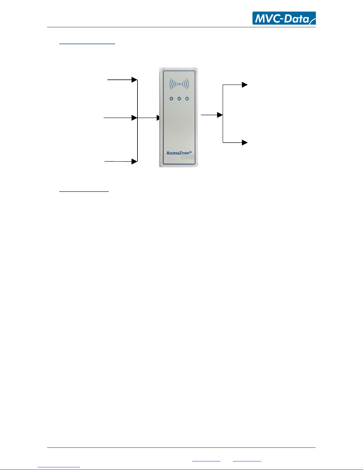
4 System Overview
This section presents a system overview with an I/O description:
5 I/O Description
GC400 series have 3 inputs and 2 outputs.
The active levels (high ‘1’/low ‘0’), when an action is performed, can be configured (inverted) for
some inputs/outputs. Please refer to section 8.5 Change System Configuration Command 2 –
Advanced settings for more details.
5.1 Inputs
Input 1 (IN1) - Not used
Input 2 (IN2) - External control of buzzer / entering configuration mode during power up
Input 3 (IN3) - External control of Red (dual) LED
Input 4 (IN4) - External control of Green (dual) LED
5.2 Outputs
Open collector type (500mA):
Output 1 (OC1) - Wiegand Data0 (D0) output for external access controller
Output 2 (OC2) – Wiegand Data1 (D1) output for external access controller
Please see the GC400 series Installation Manual for instructions on how to install the system.
All information is subject to change without notice. All other products and brand names are registered trademarks of their respective companies 2010-06-09 US 1.02
Copyright © 2005-2010 All rights reserved MVC-Data ApS Skalhuse 5 9240 Nibe Denmark Web www.mvc-data.com E-mail info@mvc-data.com Phone +45 25 12 84 02
7/33
Output 2 (OC2)
Wiegand Data1 (D1)
Output 1 (OC1)
Wiegand Data0 (D0)
Input 4 (IN4)
External Green LED
Input 2 (IN2)
External Buzzer
Input 3 (IN3)
External Red LED
AccessZone ® - GC400 Series – GC401-GC404 User Manual
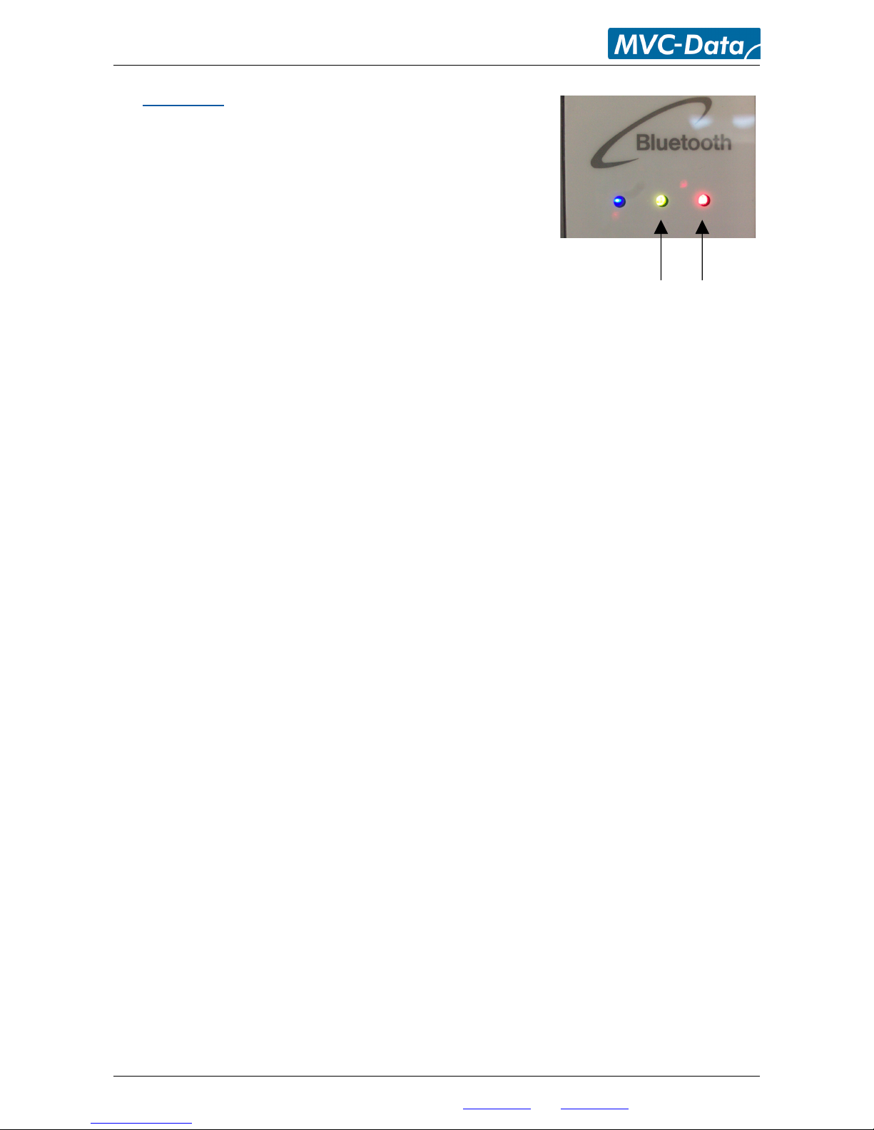
6 LED Status
The GC400 series have 3 internally controlled LEDs (Blue, Green
and Red) and two externally controlled LEDs (Red and Green) for
system indications.
The Green LED (mid) is a dual LED with an additional Red
LED. It is controlled though input 3 (Orange core)
The Red LED (right) is a dual LED with an additional Green
LED. It is controlled though input 4 (Blue core)
6.1 Power Up
The Blue LED and Red LED will light for 2 seconds from power up. This is the bootloader waiting for
new firmware.
6.2 Blue LED
Normal Mode - the Blue LED is solid on. It flashes shortly when any Bluetooth device ID is read.
Configuration Mode - the Blue LED blinks 1 time/sec. The device can accept commands
6.3 Green LED / Ext. Red LED
The Green LED flashes shortly when an Bluetooth ID has been read and is send on the Wiegand
bus.
The external Red LED is by default OFF (leave not connected). It can be controlled from an external
controller through input 3 (Orange Core). The LED is set ON by pulling input 3 down to GND.
6.4 Red LED / Ext. Green LED
The Red LED flashes shortly when an Bluetooth ID has been read but it could not be send on the
Wiegand bus because it was busy (to avoid collisions).
The external Green LED is by default OFF (leave not connected). It can be controlled from an
external controller through input 4 (Blue Core). The LED can be set ON by pulling input 4 down to
GND.
All information is subject to change without notice. All other products and brand names are registered trademarks of their respective companies 2010-06-09 US 1.02
Copyright © 2005-2010 All rights reserved MVC-Data ApS Skalhuse 5 9240 Nibe Denmark Web www.mvc-data.com E-mail info@mvc-data.com Phone +45 25 12 84 02
8/33
Dual LEDs

AccessZone ® - GC400 Series – GC401-GC404 User Manual
7 How to Configure the System
This section describes how to enter system commands and how to enable the system for
configuration. Section 8 System Commands describes the different commands in details.
7.1 Commands via Mobile
System configuration (adding/deleting users and changing system settings) can be done from any
Bluetooth enabled mobile phone.
Note!
It is not necessary to install any software on the mobile phone or use any PC tool.
The mobile phone used must support at least 20 characters as “Friendly Name” (also called
"Phone Name”). This is the name revealed for other Bluetooth devices.
A system command (e.g. "01,0022b4b62918,1234") is entered by temporarily changing the
mobiles Bluetooth “Friendly Name”. Refer to section 8 System Commands.
Please refer to the User Manual for a specific mobile phone type for how to change the Bluetooth
friendly name.
Caution!
The Bluetooth specification states a maximum length of 248 characters as Friendly Name.
However, most mobile phones have limited the space allowed for Friendly Name. A minimum of
20 characters must be supported by the used mobile phone.
All commands must be followed by an 8 digit master PIN code for safe use. The system gives 3
short beeps to indicate that a valid command has been found and the master PIN code is required.
The user will automatically be prompted when to enter the master PIN code.
Note!
This is not the normal 4 digit user access PIN code.
Please note when entering the commands:
All command parameters (enclosed by <>) must be separated by a comma ','
No spaces between values are allowed
Have the exact length as specified. I.e. no additional characters in the end
A ‘-‘ indicates an integer range 1,2,3…
All information is subject to change without notice. All other products and brand names are registered trademarks of their respective companies 2010-06-09 US 1.02
Copyright © 2005-2010 All rights reserved MVC-Data ApS Skalhuse 5 9240 Nibe Denmark Web www.mvc-data.com E-mail info@mvc-data.com Phone +45 25 12 84 02
9/33

AccessZone ® - GC400 Series – GC401-GC404 User Manual
7.2 How to enter Configuration Mode
The system must be set into configuration mode before it will accept the system commands.
However, it is possible for two privileged users (administrators) to use the Add new User and
Delete User commands in normal mode (Refer to section 7.4 How to Add or Delete Users – Normal
Operation).
Follow these steps to enter configuration mode:
Steps:
1) Power off the module
2) Pull down the buzzer input (IN2) to GND
3) Power on the module again
4) The buzzer input can be released again after the short beep
The system is now in configuration mode for 10 minutes and will flash with the Blue LED. Refer to
section 7.3 How to enter System Commands – Configuration Mode for how to enter system
commands.
The system coverage range will be limited to approximately 20 cm in the configuration period to
prevent that unauthorized people can tamper with the system.
The configuration period is restarted every time a valid command has been executed.
Configuration mode is automatically terminated after 10 minutes without any valid commands by
sending 2 short beeps or by power cycling the device to startup in normal operation (Buzzer input
(IN2) is not pulled down to GND).
Note!
The system will not scan for (detect) users in configuration mode. I.e. no Bluetooth IDs are send
on the Wiegand bus
All information is subject to change without notice. All other products and brand names are registered trademarks of their respective companies 2010-06-09 US 1.02
Copyright © 2005-2010 All rights reserved MVC-Data ApS Skalhuse 5 9240 Nibe Denmark Web www.mvc-data.com E-mail info@mvc-data.com Phone +45 25 12 84 02
10/33
 Loading...