

Page 1
AccessZone® - PcManagement™ User Manual
All information is subject to change without notice. All other products and brand names are registered trademarks of their respective companies 2014-03-13 US 0.17
Copyright © 2005-2014 All rights reserved MVC-Data ApS Skalhuse 5 9240 Nibe Denmark Web www.mvc-data.com E-mail [email protected] Phone +45 25 12 84 02
1/47
AccessZone® – PcManagement™ User Manual
User Manual for AccessZone® PcManagement™ PC tool version 2.2.2 and above
The New Generation of Wireless
Access Control Systems
Page 2
AccessZone® - PcManagement™ User Manual
All information is subject to change without notice. All other products and brand names are registered trademarks of their respective companies 2014-03-13 US 0.17
Copyright © 2005-2014 All rights reserved MVC-Data ApS Skalhuse 5 9240 Nibe Denmark Web www.mvc-data.com E-mail [email protected] Phone +45 25 12 84 02
2/47
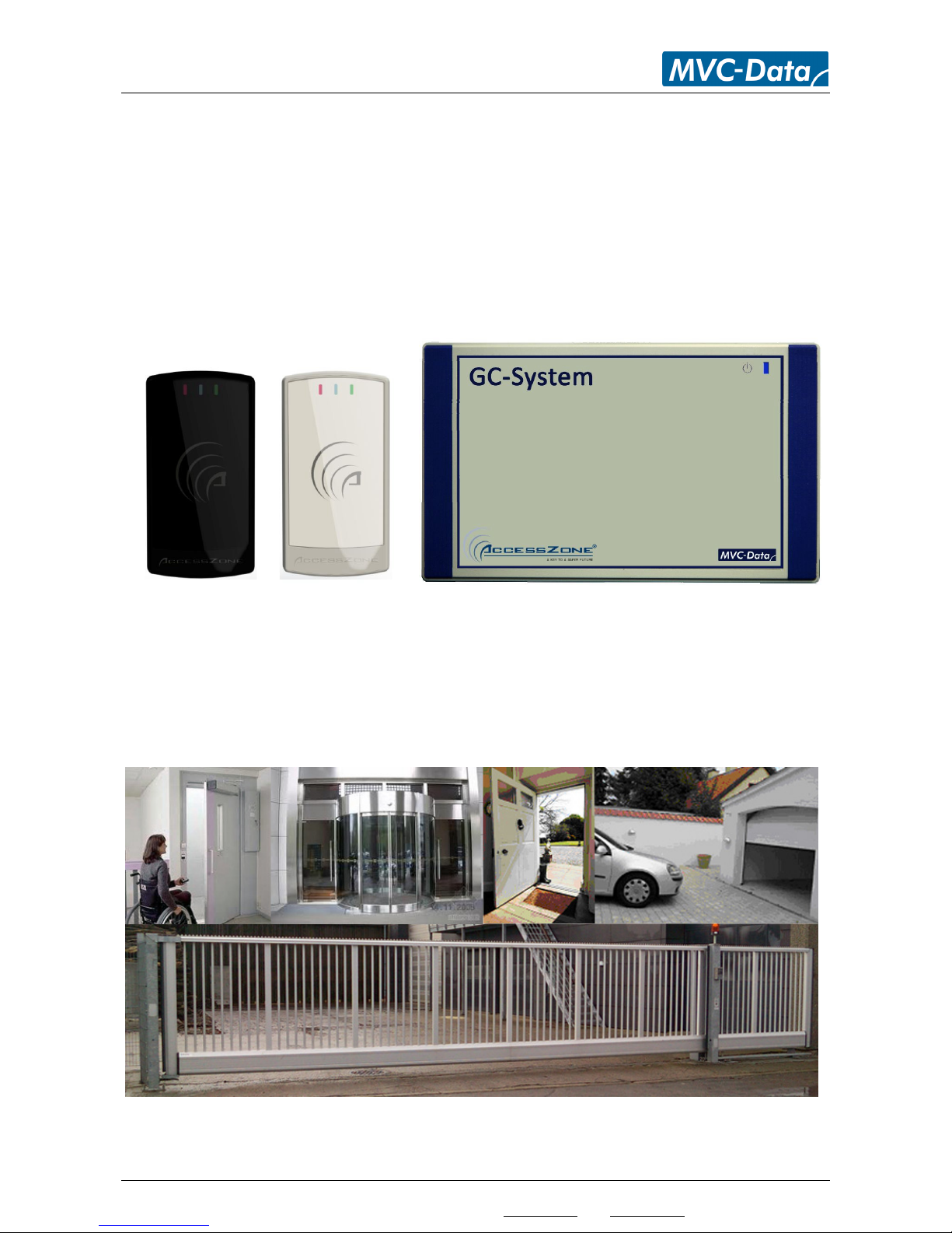
GC630/GC640/GC670 GC3000
AccessZone GateController box located near door or gate
AccessZone® System - A Key to a Safer Future
Congratulations on choosing an AccessZone® Access Control System. It is a flexible and easy to use
system for controlling access to doors and gates to private homes, shops and companies.
Look forward to the quick setup using the intuitive and graphical user interface and the system's
many built features.
This is the user manual for how to use and configure the AccessZone® PC software application
PcManagement™. It covers all AccessZone® access control systems with a PC interface
RS232/RS422/LAN/Wi-Fi and Bluetooth in the GateController™ series:
Please see the PcManagement™ PC Installation Manual for instructions on how to install the
software on a Windows XP SP2, Vista or Windows 7/8 PC.
Get easy and seamless accesses to the secured area with your mobile phone
working as a secure access key from a distance from 0.1 up to 10 meters
Page 3

AccessZone® - PcManagement™ User Manual
All information is subject to change without notice. All other products and brand names are registered trademarks of their respective companies 2014-03-13 US 0.17
Copyright © 2005-2014 All rights reserved MVC-Data ApS Skalhuse 5 9240 Nibe Denmark Web www.mvc-data.com E-mail [email protected] Phone +45 25 12 84 02
3/47
Table of Contents
1 Disclaimers ......................................................................................................................................5
2 Introduction.....................................................................................................................................6
3 What is PcManagement™ ...............................................................................................................7
3.1 Properties: ...............................................................................................................................7
4 PcManagement™ ............................................................................................................................8
4.1 Start-Up....................................................................................................................................8
4.2 Main Screen .............................................................................................................................9
4.3 Manuel Control of Door, Barrier or Gate...............................................................................10
4.4 Main Menu Overview ............................................................................................................11
4.4.1 “File”..................................................................................................................................11
4.4.2 “Settings” ..........................................................................................................................11
4.4.2.1 “Settings” –> “Access” .................................................................................................11
4.4.2.2 “Settings” –> “Program”...............................................................................................11
4.4.3 “View” ...............................................................................................................................11
4.4.4 “Search” ............................................................................................................................11
4.4.5 “Tools”...............................................................................................................................11
4.4.5.1 “Tools” –> “Firmware Upload” .....................................................................................11
4.4.5.2 “Tools” –> “Replace Gate Controller” ...........................................................................12
4.4.6 “Help”................................................................................................................................12
4.4.6.1 “Help” –> “License” .......................................................................................................12
4.4.6.2 “Help” –> “About”.........................................................................................................13
4.4.6.3 Back-up of System Configuration and User Data .........................................................13
4.5 Menu “Settings” - > “Access” -> “Users” ...............................................................................14
4.5.1 Add a new User – Menu “Settings” - > “Access” -> “Users”-> “Add”................................15
4.5.2 Add a new User – Virtual Key pad – Menu “Settings” - > “Access” -> “Users”-> “Add” ...17
4.5.3 Edit or Delete User – Menu “Settings” - > “Access” -> “Users”- “User”............................18
4.5.4 User Acceess Profile – Menu “Settings” - > “Access” -> “Users”- “Access” ......................19
4.5.5 User Acceess Notification – Menu “Settings” - > “Access” -> “Users”- “Notifications”....20
4.6 Menu “Settings”-> ”Access” -> “Access Profiles” ..................................................................21
4.6.1 Add a new Access Profile – Menu “Settings” - > “Access” -> “Access Profiles” –“Add”....22
4.6.2 Edit or Delete a Access Profile – Menu “Settings” - > “Access” -> “Access Profiles” ........23
4.7 Menu “Settings”-> “Program Settings” .................................................................................24
4.7.1 General Settings - Menu “Settings”-> “Program Settings” – “General”...........................24
4.7.2 Images - Menu “Settings”-> “Program Settings” – “Imagesl”..........................................26
4.7.3 Notifications - Menu “Settings”-> “Program Settings” – “Notifications”.........................27
4.7.4 Notifications - Menu “Settings”-> “Program Settings” – “Remote Control” ....................28
4.7.4.1 Remote Client Connection Status..................................................................................29
4.8 GateController™ Settings –“Gates” .......................................................................................30
4.8.1 Time Profile - Menu “Opening Hours” ..............................................................................30
4.8.2 Gate Settings - Menu “Settings” ......................................................................................32
4.8.3 Key Detection Range - Menu “Key Detection” ..................................................................36
4.8.4 System Info - Menu “Info”.................................................................................................38
4.8.5 System Images - Menu “Images”......................................................................................39
4.8.6 Input/Output Settings - Menu “IO Setup”.........................................................................40
4.9 Database Search Tool – Menu “Search” -> “Access Log” ......................................................42
4.10 Tools – Menu “Tools” ............................................................................................................43
4.10.1 Firmware Upload Tool - Menu “Tools”-> “Firmware Upload” ........................................43
4.10.2 Replace GateController Tool - Menu “Tools”-> “Replace Gate Controller” ....................43
Page 4

AccessZone® - PcManagement™ User Manual
All information is subject to change without notice. All other products and brand names are registered trademarks of their respective companies 2014-03-13 US 0.17
Copyright © 2005-2014 All rights reserved MVC-Data ApS Skalhuse 5 9240 Nibe Denmark Web www.mvc-data.com E-mail [email protected] Phone +45 25 12 84 02
4/47
5 Mobile Phone as Access Key .........................................................................................................44
6 GPS Antenna as Access Key...........................................................................................................44
7 AccessZone® Bluetooth Tags.........................................................................................................44
8 External Buttons............................................................................................................................45
8.1 Request Exit – REX Push Button.............................................................................................45
8.1.1 Request Exit.......................................................................................................................45
8.1.2 Alarm Arming and Disarming ...........................................................................................45
8.1.3 Disarming the Alarm .........................................................................................................45
8.1.4 Arming the Alarm..............................................................................................................45
8.2 Timing Diagram of the outputs – Normal Access and Arming the Alarm .............................46
8.3 Timing Diagram of the Outputs – Normal Access and Reject Arming of the Alarm..............46
9 Default Factory System Settings ...................................................................................................47
9.1 GC630/GC640 Series..............................................................................................................47
9.2 GC3000 Series ........................................................................................................................47
Page 5

AccessZone® - PcManagement™ User Manual
All information is subject to change without notice. All other products and brand names are registered trademarks of their respective companies 2014-03-13 US 0.17
Copyright © 2005-2014 All rights reserved MVC-Data ApS Skalhuse 5 9240 Nibe Denmark Web www.mvc-data.com E-mail [email protected] Phone +45 25 12 84 02
5/47
1 Disclaimers
All rights reserved.
MVC-Data ApS assumes no responsibility for any errors in this manual.
MVC-Data ApS is constantly working to improve its products and offer new features in
collaboration with customers and partners. Therefore, MVC-Data ApS reserves the right to change
the hardware, software and / or specifications without notice and shall have no obligation to
update the information contained in this manual.
MVC-Data ApS's products are not authorized for use as system-critical components in life
supporting devices or systems.
AccessZone® is a registered trademark of MVC-Data ApS. PcManagement™ is a trademark of MVCData ApS.
The Bluetooth trademark is owned by the Bluetooth SIG. All other trademarks are owned by their
respective owners.
The displayed screen images may differ.
Copyright © 2005-2014 MVC-Data ApS
Page 6

AccessZone® - PcManagement™ User Manual
All information is subject to change without notice. All other products and brand names are registered trademarks of their respective companies 2014-03-13 US 0.17
Copyright © 2005-2014 All rights reserved MVC-Data ApS Skalhuse 5 9240 Nibe Denmark Web www.mvc-data.com E-mail [email protected] Phone +45 25 12 84 02
6/47
2 Introduction
The AccessZone® Access Control Systems are well suited for use in private homes, shops and
companies and can be scaled from a single GateController™ to multiple GateControllers.
They are unique wireless access control systems built on Bluetooth wireless technology – a
wireless technology that operates in the license free ISM band at 2.4 GHz.
The systems only allow access to users who can be identified by their unique Key ID and optional a
4 digit PIN code for increased security. The used mobile phones or other Bluetooth devices must
be set to “visible” to allow them to be discovered by the system.
This eliminates the need for mechanical readers and keyboards outside the secured area. This
removes the risk for property damage and breakdown due to harsh environmental conditions and
heavy use.
A feature might require a firmware update of your system to be supported. Please refer to the
GC630/GC640/GC670 or GC3000 firmware Release Note for the latest updates.
Page 7

AccessZone® - PcManagement™ User Manual
All information is subject to change without notice. All other products and brand names are registered trademarks of their respective companies 2014-03-13 US 0.17
Copyright © 2005-2014 All rights reserved MVC-Data ApS Skalhuse 5 9240 Nibe Denmark Web www.mvc-data.com E-mail [email protected] Phone +45 25 12 84 02
7/47
3 What is PcManagement™
AccessZone® PcManagement™ System is the PC application/server that handles the user interface
for the AccessZone® GateController™ systems, which are connected to gates, barriers, locks and
other locking mechanisms.
3.1 Properties:
Easy and seamless access with your Bluetooth® enabled mobile phone, PDA or GPS
– No tags or cards needed
Fully featured access control system with booking feature
Exceptional, fast and unique mobile identification with Bluetooth®
Up to 16 character Administrator PIN code for secure use. Operator Mode for view only
High security with individual user access PIN code and tamper alarm
Scalable for up to 2000 simultaneous users – all stored locally in the GateController
Fast registration of a new key at the gate within a few seconds
Unique time profiles for each GateController™
Individual and group user access profiles
Grant and revoke user access at a glance
Grant instant access from the graphical user interface
Voluntary SMS or E-mail on selected events
Control and monitor multiple gates from a single PC
Register all events in database for later analysis
Stores all access in a database for later analysis
Supports typical database functions – search who and what gate etc.
Provides simultaneous support for multiple GateControllers
Advanced system settings are configurable via XML file
Server option for remote control of access via LAN/WAN
Supports PC interface with RS232/RS422/LAN/Wi-Fi (IP) or Bluetooth
Robust housing (IP40 indoor use/IP65 outdoor use depending on type)
Easy firmware upgrade with bootloader
Low installation and maintenance costs
RoHS compliant and low power consumption
Please refer to the:
AccessZone® PcManagement™ PC Installation Manual for instructions on how to install the
application on a PC. Refer to AccessZone PcManagement PC Installation Manual
AccessZone® - Remote™ client User Manual for instructions on how to use the remote
client application. Refer to AccessZone - Remote User Manual
GC630/GC640 or GC3000 Series Installation Manual for instructions on how to install the
system:
o AccessZone GC630/GC640 Installation Manual
o AccessZone GC3000 Installation Manual
More information on: http://www.mvc-data.com/Manuals.html
Page 8

AccessZone® - PcManagement™ User Manual
All information is subject to change without notice. All other products and brand names are registered trademarks of their respective companies 2014-03-13 US 0.17
Copyright © 2005-2014 All rights reserved MVC-Data ApS Skalhuse 5 9240 Nibe Denmark Web www.mvc-data.com E-mail [email protected] Phone +45 25 12 84 02
8/47
4 PcManagement™
4.1 Start-Up
The program can be started by clicking the AccessZone® PC Management short cut on the desktop
or from Windows All Program “MVC-Data AccessZone” application menu. It can also be started by
double clicking on the file PcManagement.exe in the installation directory.
The image above shows the AccessZone® PcManagement™ System start-up screen. The system is
initialized according to information in the XML configuration file and opens the database with
GateControllers and user information.
Select ”Administrator Mode” by clicking ”Yes”. Or ”Operator Mode” (view only) by clicking ”No”.
Enter the administrator PIN code if used or leave empty and click ”OK”. Max. up to 16 characters
If ”Cancel” is selected it automatically starts up in ”Operator Mode”.
Page 9

AccessZone® - PcManagement™ User Manual
All information is subject to change without notice. All other products and brand names are registered trademarks of their respective companies 2014-03-13 US 0.17
Copyright © 2005-2014 All rights reserved MVC-Data ApS Skalhuse 5 9240 Nibe Denmark Web www.mvc-data.com E-mail [email protected] Phone +45 25 12 84 02
9/47
4.2 Main Screen
The image below shows how the main screen is organized.
The upper left screen shows a customized overview image (e.g. CAD drawing) of the secured area
or building. You can freely make your own drawing of the secure area/building. The overview
image can be enabled/disabled.
The different door, barrier and gate symbols can also be customized and be placed freely anyway
on the overview drawing. The symbols are automatically updated according to the status events
for all the connected GateControllers. I.e. is the door/barrier/gate open or closed etc.
You can design an overview image which looks like the real environment to ease identification of
the user accesses and other events.
To the right video images can be shown from a freely selected folder on the PC or server for each
GateController™. The images are automatically updated to show the latest image. I.e. it can be
images from surveillance cameras at the location. The system administrator can then get a visual
indication of the last access as well. This can be enabled/disabled.
The bottom half shows an event log for all detected users and other events in real time.
Bottom left shows a list with all the controlled GateControllers. Below a list of all registered users
(SBD-keys) for easy maintenance and last a list with all the profiles and the users associated with
each profile for an easy overview.
General!
A feature must be enabled for a GateController™ and for a user before it becomes active. I.e.
this makes it possible to enable a feature for a GateController™ and then specify whatever the
feature is going to be used for each user. And a feature can be permanently disabled for all users
by disabling the feature for the GateController™ etc.
Page 10
AccessZone® - PcManagement™ User Manual
All information is subject to change without notice. All other products and brand names are registered trademarks of their respective companies 2014-03-13 US 0.17
Copyright © 2005-2014 All rights reserved MVC-Data ApS Skalhuse 5 9240 Nibe Denmark Web www.mvc-data.com E-mail [email protected] Phone +45 25 12 84 02
10/47
4.3 Manuel Control of Door, Barrier or Gate
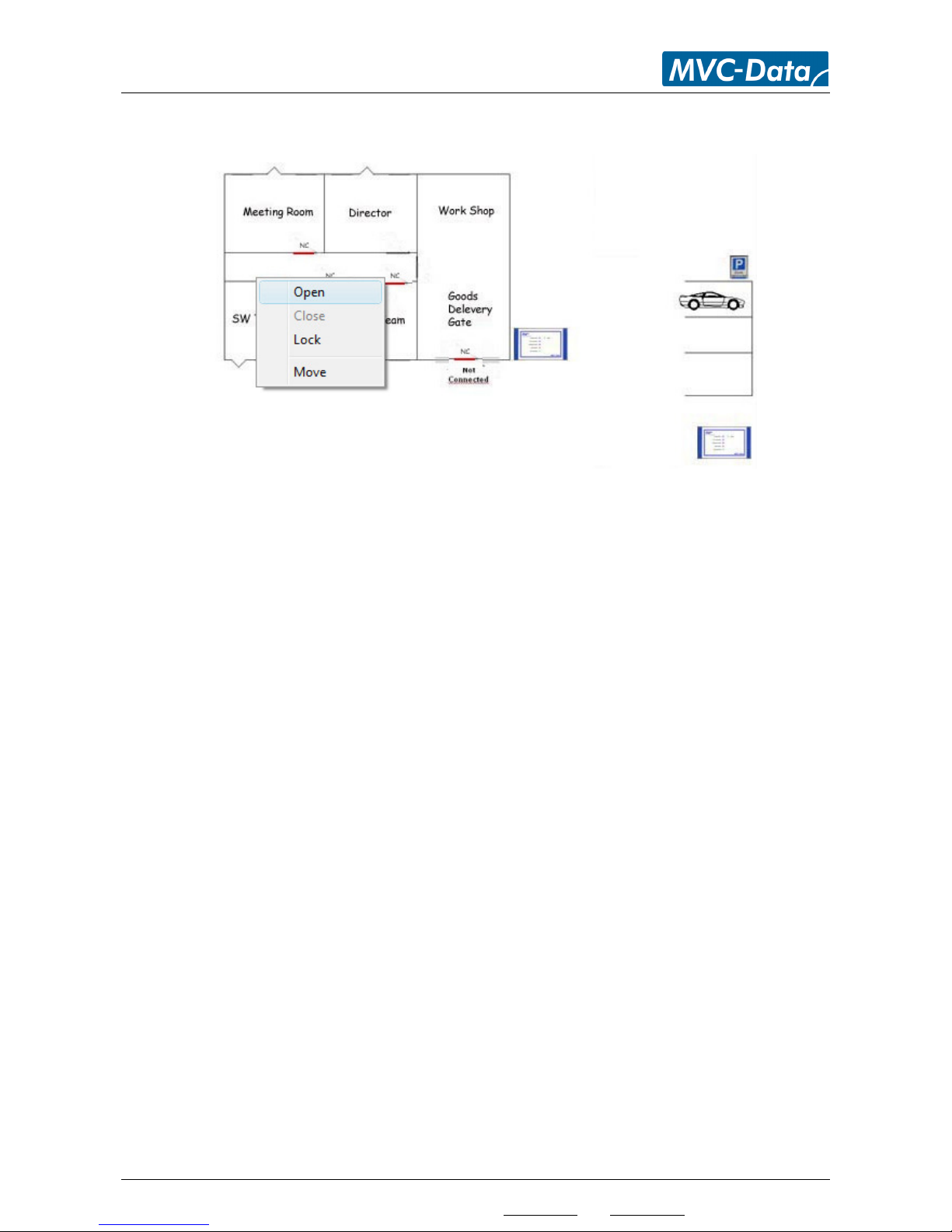
It is easy and fast to control a door, barrier or gate directly from the graphical user interface.
Simply right-click on a door/barrier/gate symbol on the customized image (CAD drawing) of the
secured area and then open/close or lock it manually - easy, quick and intuitive.
The desired command is sent to the selected GateController™ which executes the command and
sends back a status event.
The graphical symbols are updated to show current door/barrier/gate status. You can also edit the
settings for the selected GateController™.
Page 11
AccessZone® - PcManagement™ User Manual
All information is subject to change without notice. All other products and brand names are registered trademarks of their respective companies 2014-03-13 US 0.17
Copyright © 2005-2014 All rights reserved MVC-Data ApS Skalhuse 5 9240 Nibe Denmark Web www.mvc-data.com E-mail [email protected] Phone +45 25 12 84 02
11/47
4.4 Main Menu Overview
4.4.1 “File”
This menu contains the "Exit" function to terminate the program. The program can also be
terminated with (Ctrl + X)
4.4.2 “Settings”
This menu contains two functions ”Access” (Ctrl+A) and ”Program” (Ctrl-P)
4.4.2.1 “Settings” –> “Access”
Add new users, edit properties for exiting users or delete users. Setup an access profile or
edit/delete an exiting profile. This can also be done from the graphical user interface to the left.
4.4.2.2 “Settings” –> “Program”
To setup some basic program settings controlling how the system operates and enabling of
administrator PIN code. Other settings are handled in the XML configuration file (typical path
c:\ProgramData\AccessZone\config.xml).
4.4.3 “View”
This menu contains check boxes for adjusting the horizontal displayed event information in the
real time monitor window. Click information on and off regarding door/gate entries (Opened,
closed or locked). The information is always stored in the system database for later analysis.
The system log (Ctrl+L) shows system status and events. This information is also written in the log
file (typical path c:\ProgramData\AccessZone\log\PcManagementLog.log)
4.4.4 “Search”
This menu contains the "Access Log" function. Here you can specify your search filters and search
through the database of stored accesses and other events. It can also be started by pressing the
“F3”-key.
4.4.5 “Tools”
This menu provides access to the two tools “Firmware Upload” and “Replace GateController”.
4.4.5.1 “Tools” –> “Firmware Upload”
The “Firmware Upload” tool is used to upload new firmware to the systems. Refer to the
“Firmware Upload User Manual”. PcManagement™ must be closed to run this tool.
Page 12
AccessZone® - PcManagement™ User Manual
All information is subject to change without notice. All other products and brand names are registered trademarks of their respective companies 2014-03-13 US 0.17
Copyright © 2005-2014 All rights reserved MVC-Data ApS Skalhuse 5 9240 Nibe Denmark Web www.mvc-data.com E-mail [email protected] Phone +45 25 12 84 02
12/47
4.4.5.2 “Tools” –> “Replace Gate Controller”
The “Replace Gate Controller” tool makes it easy to exchange a GateController™. I.e. all the
settings and profiles are copied to the new GateController™ and the old GateController™ can be
removed.
4.4.6 “Help”
This menu contains two functions "License .." for handling the license file and an "About…" box
with system information (license information and running time)
4.4.6.1 “Help” –> “License”
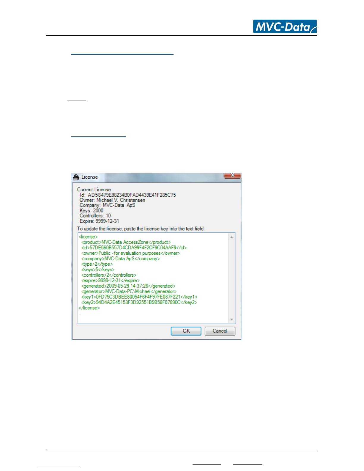
This option contains the license function for Copy&Past of the license information.
Copy the license information from your purchased license file and past it into the text field.
Click OK to store the license.
Please restart PcManagement™ to allow it to activate the new license.
Page 13

AccessZone® - PcManagement™ User Manual
All information is subject to change without notice. All other products and brand names are registered trademarks of their respective companies 2014-03-13 US 0.17
Copyright © 2005-2014 All rights reserved MVC-Data ApS Skalhuse 5 9240 Nibe Denmark Web www.mvc-data.com E-mail [email protected] Phone +45 25 12 84 02
13/47
4.4.6.2 “Help” –> “About”
This option contains the about box function with system information: PcManagement™ version,
license information (ID and rights etc.), started time and the folder path where user program
information is stored and a link to a support web page to locate more information (updates).
This is the path to the program data folder (typically a hidden folder) where the configuration data
is stored.
Check the “About” box for your system. It may differ and depends on the used Windows version.
4.4.6.3 Back-up of System Configuration and User Data
The “Data folder” shown above contains the user data files: db.mdb and config.xml with all your
system settings and user data.
It is recommended to take regular backups of this folder to a backup media for easy restoring of
your system in case of a PC break down etc.
You can also move your system to another PC by restoring these files in the “Data folder”. First
install PcManagement on the new PC. Copy your system files from the old PC to the data folder on
the new PC.
Page 14
AccessZone® - PcManagement™ User Manual
All information is subject to change without notice. All other products and brand names are registered trademarks of their respective companies 2014-03-13 US 0.17
Copyright © 2005-2014 All rights reserved MVC-Data ApS Skalhuse 5 9240 Nibe Denmark Web www.mvc-data.com E-mail [email protected] Phone +45 25 12 84 02
14/47
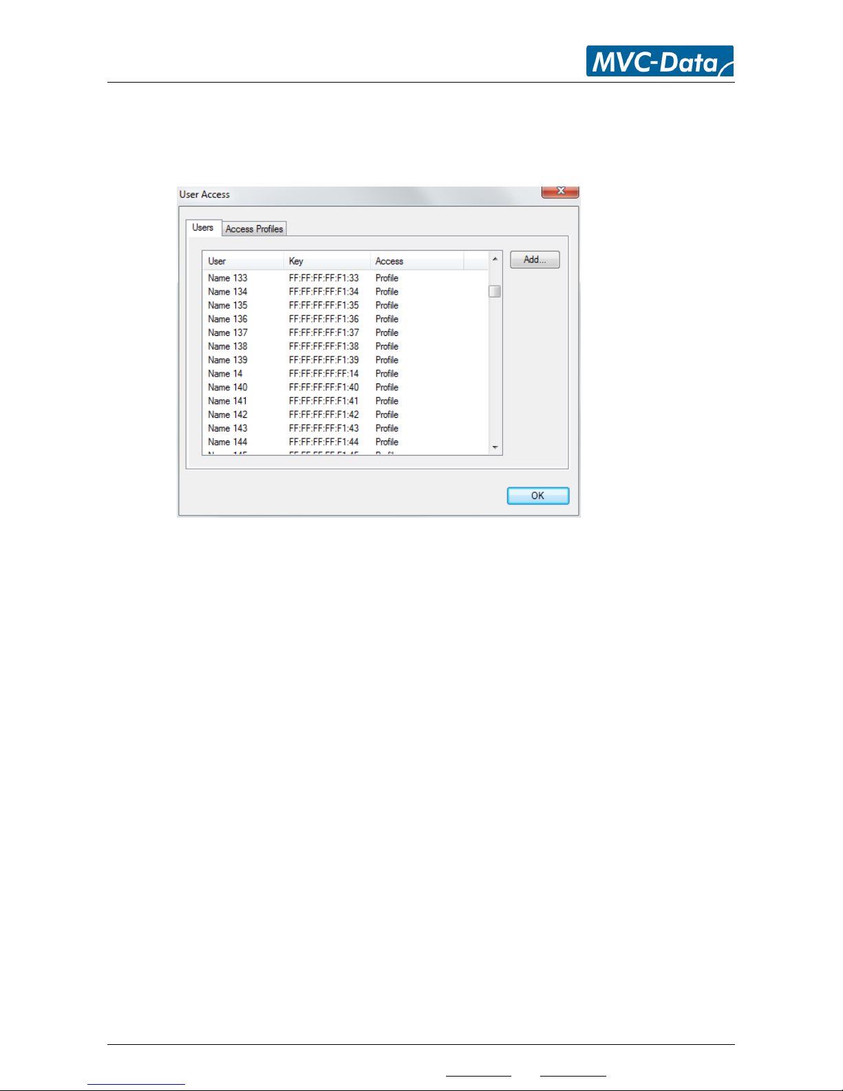
4.5 Menu “Settings” - > “Access” -> “Users”
This menu shows all users and their access rights.
Click Add to add a new user or click on an exiting user to edit options or delete the user.
Page 15
AccessZone® - PcManagement™ User Manual
All information is subject to change without notice. All other products and brand names are registered trademarks of their respective companies 2014-03-13 US 0.17
Copyright © 2005-2014 All rights reserved MVC-Data ApS Skalhuse 5 9240 Nibe Denmark Web www.mvc-data.com E-mail [email protected] Phone +45 25 12 84 02
15/47
4.5.1 Add a new User – Menu “Settings” - > “Access” -> “Users”-> “Add”
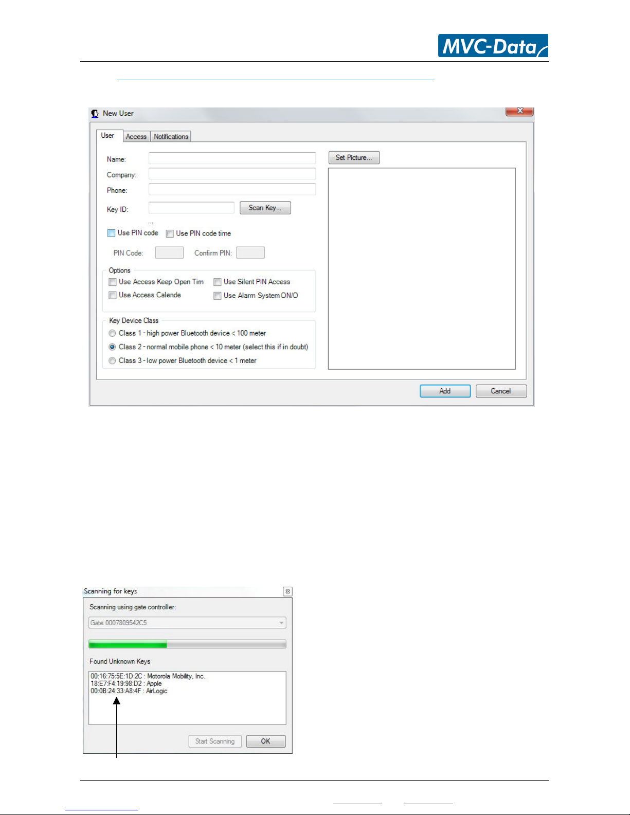
This menu shows the “New User” form to fill out for the new user.
First enter the name of the user and relevant “company” information. The “Company” field can
also be used to save additional information about the user e.g. company name of employee or
employment group for the user etc. You can also add a phone number and select "Set Picture" to
add a picture of the user.
The unique BD address (user ID) of the user’s mobile phone or other Bluetooth enabled device can
be manually entered in the “Key ID” field or select “Scan” to automatically scan for the user’s
unique BD address.
The view below shows the system while it automatically scans for new users (SBD keys). The
scanning is started manually by clicking the "Scan" button. The detected user IDs (SBD-Keys) and
manufacture names (E.g. Apple for iPhones) are listed as they are found:
When the Key ID is found, mark it in the list and
click "OK"
Note!
Any GateController™ can be used to scan for
devices. Click the drop down menu to select the
desired GateController™
It is recommended to use a specific
GateController™ with a short detection range to
avoid lists with many detected keys.
Unique user IDs
Page 16
AccessZone® - PcManagement™ User Manual
All information is subject to change without notice. All other products and brand names are registered trademarks of their respective companies 2014-03-13 US 0.17
Copyright © 2005-2014 All rights reserved MVC-Data ApS Skalhuse 5 9240 Nibe Denmark Web www.mvc-data.com E-mail [email protected] Phone +45 25 12 84 02
16/47
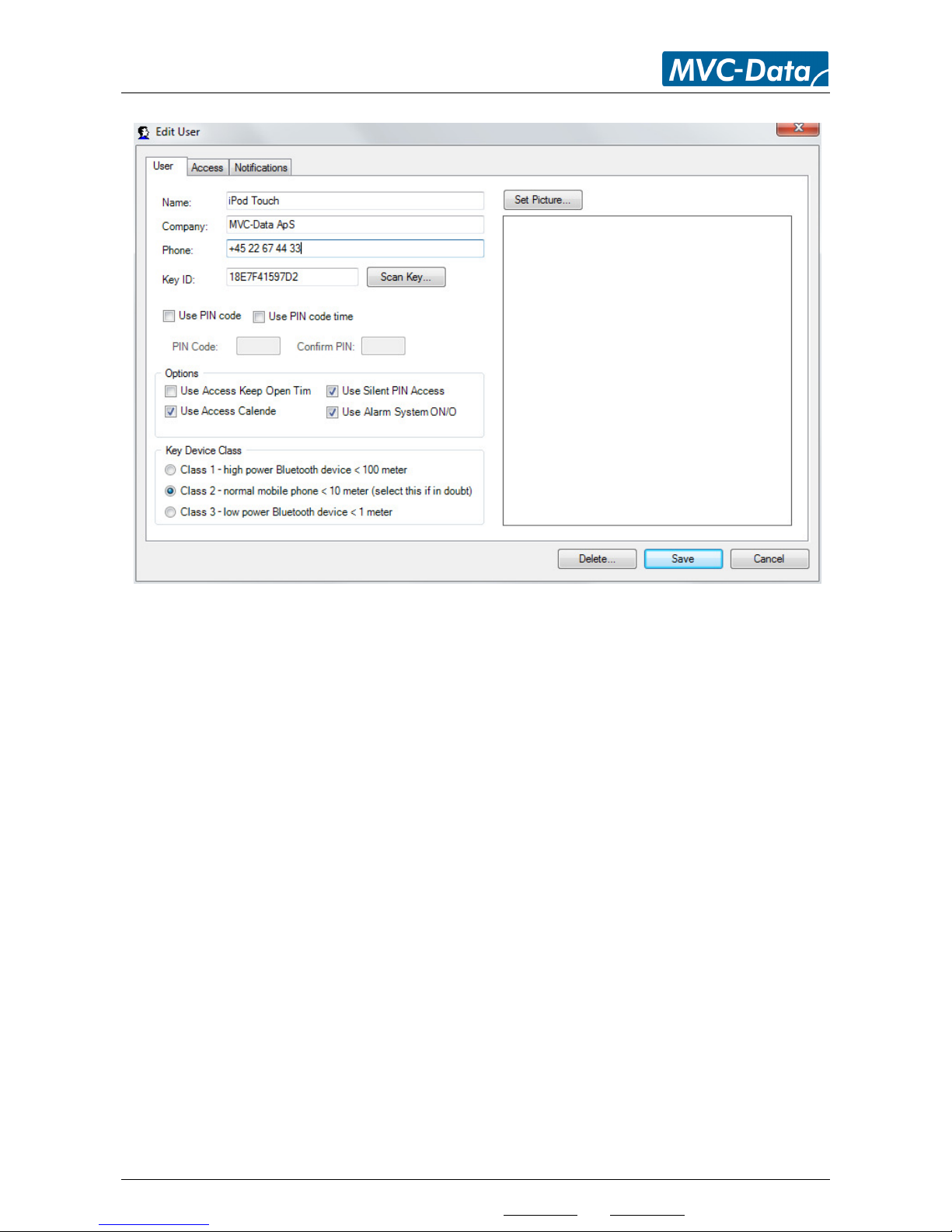
Rights and settings are filled out for the user:
Select whatever the user must use PIN code to get access or just within a specified PIN code time.
The PIN code time can be the same or set differently for each GateController™. I.e. PIN code may
be required at different times depending on the GateController’s location in the system.
Select which options the user must use (no options are selected by default):
“Use Access Keep Open Time” will allow the user to keep the door/gate open within the
specified time period
“Use Access Calendar” will enforce the user to comply with the GateController calendar
“Use Silent PIN Access” will allow the user to enter a special “silent” access PIN code. The
user must type the PIN code 4 times to activate. The door/gate will be open as normal but
an alarm is trigged in the system to alert system administer/security personal
“Use Alarm System ON/OFF” will allow the user to switch an alarm system ON and OFF
Last select the device power class for the user (device):
Class 1 = “strong device” Class 2 = “standard device” Class 3 = “weak device”
If a user’s device must be closer to the reader than most others before access is granted
- select class 3 = “weak device”.
If a user’s device gives access further away from the reader than most others
- select class 1 = “strong device”.
Click “Add” to add the user or “Cancel” to leave without adding the user.
TIP!
A mobile phone is typically a class 2 device. If you are in doubt select Class 2 (default).
Remember a feature must also be enabled in the GateController™ for it to work.
Page 17

AccessZone® - PcManagement™ User Manual
All information is subject to change without notice. All other products and brand names are registered trademarks of their respective companies 2014-03-13 US 0.17
Copyright © 2005-2014 All rights reserved MVC-Data ApS Skalhuse 5 9240 Nibe Denmark Web www.mvc-data.com E-mail [email protected] Phone +45 25 12 84 02
17/47
4.5.2 Add a new User – Virtual Key pad – Menu “Settings” - > “Access” -> “Users”-> “Add”
The system supports a virtual keypad feature which can operate in two different modes: Virtual
Key Only Mode and Virtual Keypad Mixed Mode
This feature will allow access to all users that know the 4 digit access PIN code.
4.5.2.1 Only Mode
The system can be configured to run as a purely virtual key pad. I.e. no specific users have to be
added.
Common keypad:
The system administrator adds a "user" with the special BD address “FFFFFFFFFFFF” (not a valid BD
address) and the desired 4 digit access PIN code. This "user" and access PIN code is the same for
all GateControllersTM in the system.
Individual keypad:
The system administrator adds a "user" with the special BD address “FFFFFFxxxxxx” (not a valid BD
address) and the desired 4 digit access PIN code. "xxxxxx" is the GateControllers lower address
part, in example with 00078043633F xxxxxx = 43633F and can be found in the "Info" box. This
"user" and access PIN code is individual for that GateControllerTM.
The system will in this mode grant access to all users which enter the correct 4 digit virtual keypad
access PIN code.
The PIN code can be disabled if “0000” is used as PIN code and thereby give access to all with a
Bluetooth enabled device – a simple gate/door opener.
TIP!
The system administrator can at any time change the PIN code. E.g. on a daily or weekly basis.
4.5.2.2 Mixed Mode
The system can also be configured to be in mixed mode virtual key pad with up to the system limit
minus 1 (number of supported users depends on the license acquired) of unique users and a
virtual keypad user with the special common BD address “FFFFFFFFFFFF” or individual BD address
"FFFFFFxxxxxx" and the 4 digit access PIN code.
The system will in this mode grant access to all individually added users with their unique 4 digit
access PIN code and to all other unknown users which enter the correct 4 digit virtual keypad
access PIN code.
TIP!
This feature allows the virtual keypad PIN code to be changed without affecting all the individually
added users.
The common virtual keypad can be combined with the individual keypad "user" on selected
GateControllers. If both the virtual keypad "user" and the individual "user" are used with a
GateController - the individual PIN code is used.
Page 18
AccessZone® - PcManagement™ User Manual
All information is subject to change without notice. All other products and brand names are registered trademarks of their respective companies 2014-03-13 US 0.17
Copyright © 2005-2014 All rights reserved MVC-Data ApS Skalhuse 5 9240 Nibe Denmark Web www.mvc-data.com E-mail [email protected] Phone +45 25 12 84 02
18/47
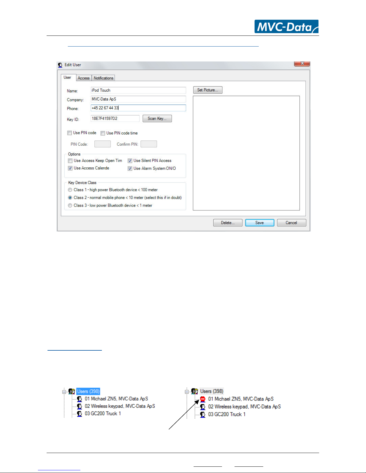
4.5.3 Edit or Delete User – Menu “Settings” - > “Access” -> “Users”- “User”
Click on an existing User in the list to make changes to the user settings:
Edit the user settings. Select “Access” or “Notifications” to make further changes:
Save: Click “Save” when done to store the new settings
Delete: Click “Delete” to completely remove the user from the system
Cancel: Click “Cancel” to leave the menu without making any changes
TIP!
A user can be temporally disabled from the system in case of a lost user key (mobile phone) by
setting the users access permission to “Block All Access”. The user will be detected but no
admission will be allowed. The system must be online to update the GateControllers. The access
event attempt is still logged in the database and an email notification can be send. Please refer to
User Acceess Profile
You can also select the users directly from the drop down list shown on the graphical user
interface to the left by double clicking on a user:
User is now temporally blocked
Page 19
AccessZone® - PcManagement™ User Manual
All information is subject to change without notice. All other products and brand names are registered trademarks of their respective companies 2014-03-13 US 0.17
Copyright © 2005-2014 All rights reserved MVC-Data ApS Skalhuse 5 9240 Nibe Denmark Web www.mvc-data.com E-mail [email protected] Phone +45 25 12 84 02
19/47
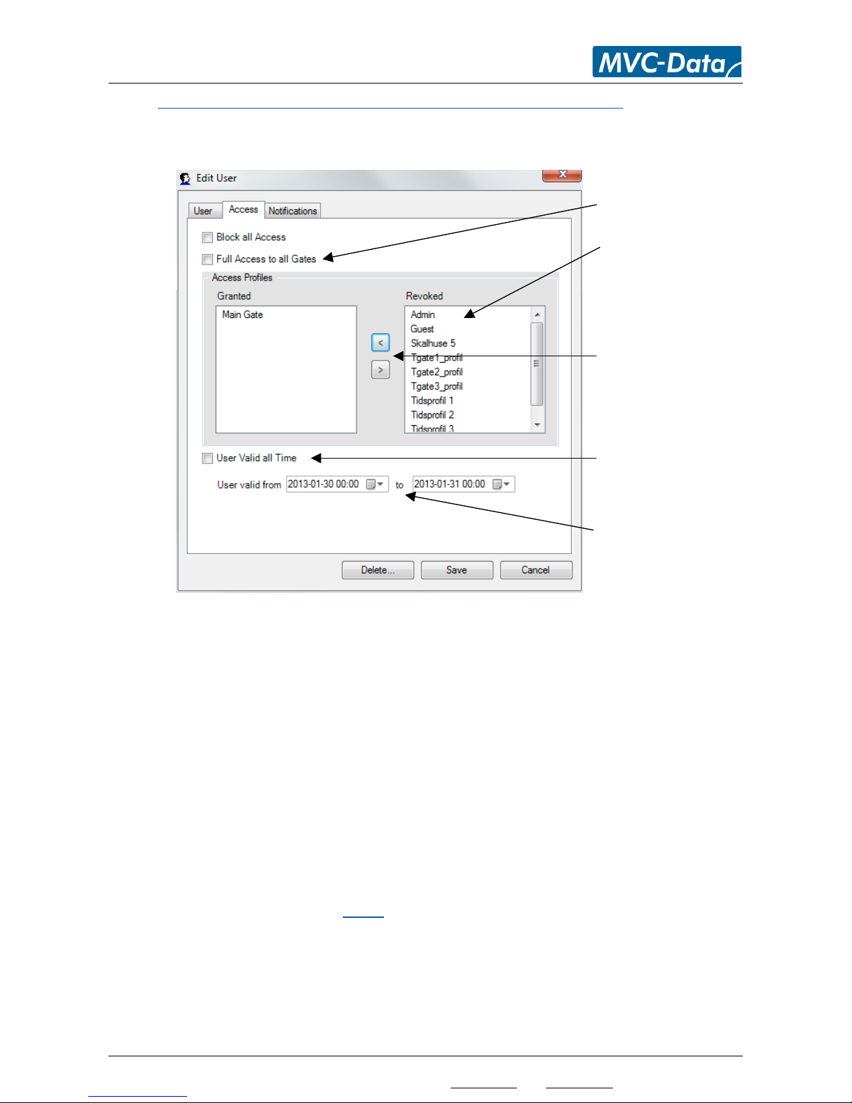
4.5.4 User Acceess Profile – Menu “Settings” - > “Access” -> “Users”- “Access”
This view shows the menu for specifying the access rights for the new user. You can select multiple
profiles for each user:
“Block All Access” select to (temporarily) block all access for a particular user
“Full Access to all Gates” select to allow full access disregarding any time profiles on all
doors/barriers/gates. This profile should only be used with a limited number of users.
This is the default setting
Select an access profile. Remove all markings from “Block All Access” and “Full Access to all
Gates” to select from the list of access profiles. One or more access profiles can be
selected. Click the ‘<’ symbol to add the access profile or ‘>’ symbol remove the access
profile
Booking Option:
Remove the mark from "User Valid all Time" (default) to allow the user to be enrolled after the
calender. I.e. the user can be added now but first be enrolled at a later date. A user also be
enrolled and automatically be removed at a specific date without further interaction.
Note! Booking is only working with online GateControllers.
Edit the user access settings. Select “User” or “Notifications” to make further changes.
Save: Click “Save” when done to store the new settings
Delete: Click “Delete” to completely remove the user from the system
Cancel: Click “Cancel” to leave the menu without making any changes
Click "Full Access to all
Gates" or select an access
profile from the list.
”<” to add or ”>” to remove
the selected access profile
Remove the mark to enable
booking feature.
Enter the start - and end
date and clock for the user.
Page 20
AccessZone® - PcManagement™ User Manual
All information is subject to change without notice. All other products and brand names are registered trademarks of their respective companies 2014-03-13 US 0.17
Copyright © 2005-2014 All rights reserved MVC-Data ApS Skalhuse 5 9240 Nibe Denmark Web www.mvc-data.com E-mail [email protected] Phone +45 25 12 84 02
20/47
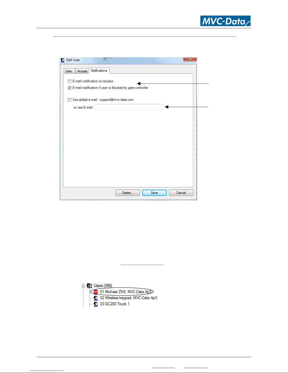
4.5.5 User Acceess Notification – Menu “Settings” - > “Access” -> “Users”- “Notifications”
This view shows the menu for specifying the email notification to send for all access for a
particular user:
“E-mail notification on access” select if an email notification is required on all access for
that particular user
“E-mail notification if user is blocked by gate controller” select if an email notification is
required in case the system blocks that particular user for any further accesses.
This could be the case if the user has entered the 4 digit access PIN code wrong 3 times in a
row. System administrator must then remove the “Block All Access” marking for the user to
allow access again. See section User Acceess Profile.
The user will be marked as blocked in the user list to the left:
“Use global email” specify whatever the global email account should be used to send the
event or specify a custom one for that particular user
Edit the notification settings. Select “User” or “Access” to make further changes and click “Save”
when done to store the new settings.
Click a notification to
enable it.
Specify to use a
common email
address or enter a
unique email address
for that particular
user
Page 21
AccessZone® - PcManagement™ User Manual
All information is subject to change without notice. All other products and brand names are registered trademarks of their respective companies 2014-03-13 US 0.17
Copyright © 2005-2014 All rights reserved MVC-Data ApS Skalhuse 5 9240 Nibe Denmark Web www.mvc-data.com E-mail [email protected] Phone +45 25 12 84 02
21/47
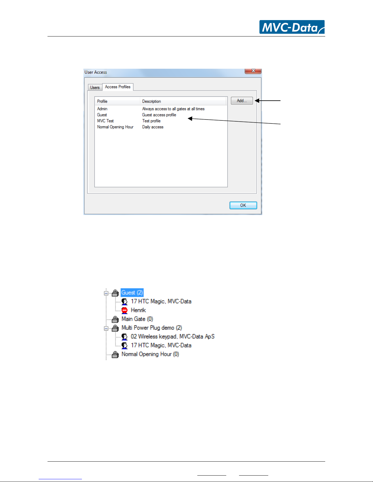
4.6 Menu “Settings”-> ”Access” -> “Access Profiles”
This view shows an overview of the exiting Access Profiles.
Click “Add” to add a new access profile or click on an exiting access profile to edit the options or to
delete it.
Click “OK” when done.
The access profiles can also be selected directly from the graphical user interface to the left. It also
shows which users who use the profile:
Click ”Add” to make a
new access profile
Click on an existing
access profile to edit
Page 22
AccessZone® - PcManagement™ User Manual
All information is subject to change without notice. All other products and brand names are registered trademarks of their respective companies 2014-03-13 US 0.17
Copyright © 2005-2014 All rights reserved MVC-Data ApS Skalhuse 5 9240 Nibe Denmark Web www.mvc-data.com E-mail [email protected] Phone +45 25 12 84 02
22/47
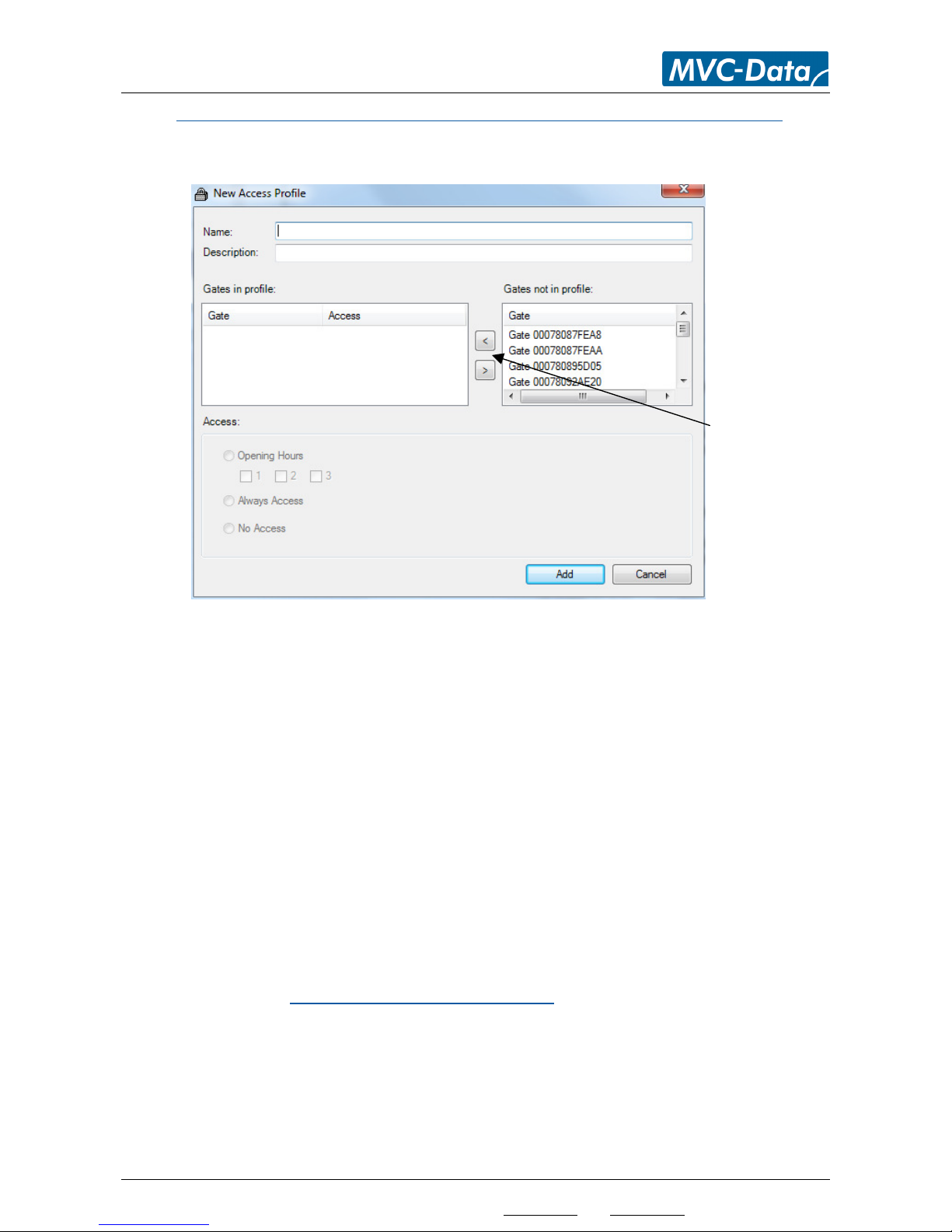
4.6.1 Add a new Access Profile – Menu “Settings” - > “Access” -> “Access Profiles” –“Add”
This view shows the new Access Profile menu. This menu can also be open by right clicking on the
“Profile” drop down list in the graphical user interface to the left.
“Name” specify the profile name
“Description” write a short description to make it easy to understand the purpose of the
Access Profile
“Gates in profile” select all the doors/gates to use with that Access Profile
“Gates not in profile” use the ‘<’ or ‘>’ to add or remove doors/gates from the Access
Profile
“Access” specifies the time profile to use in the Access Profile for each of the selected
GateControllers in the Access Profile. Click “Opening Hours” to select any combination e.g.
1 and 3 or 1 and 2 etc. of the defined time profiles or “Full Access” or “No Access” (blocked
mode)
Note!
The time profiles may differ between GateControllers depending on user selection. Refer
to section 4.8.1 Time Profile - Menu “Opening Hours”
Click “Add” to store the new Access Profile. Click “Cancel” to leave without changes.
TIP!
Remember to add a new GateController™ to new and any existing access profiles as required
allowing the profiles to work with the new GateController™.
Click ”<” to add or
”>” to remove the
selected GateController
Page 23
AccessZone® - PcManagement™ User Manual
All information is subject to change without notice. All other products and brand names are registered trademarks of their respective companies 2014-03-13 US 0.17
Copyright © 2005-2014 All rights reserved MVC-Data ApS Skalhuse 5 9240 Nibe Denmark Web www.mvc-data.com E-mail [email protected] Phone +45 25 12 84 02
23/47
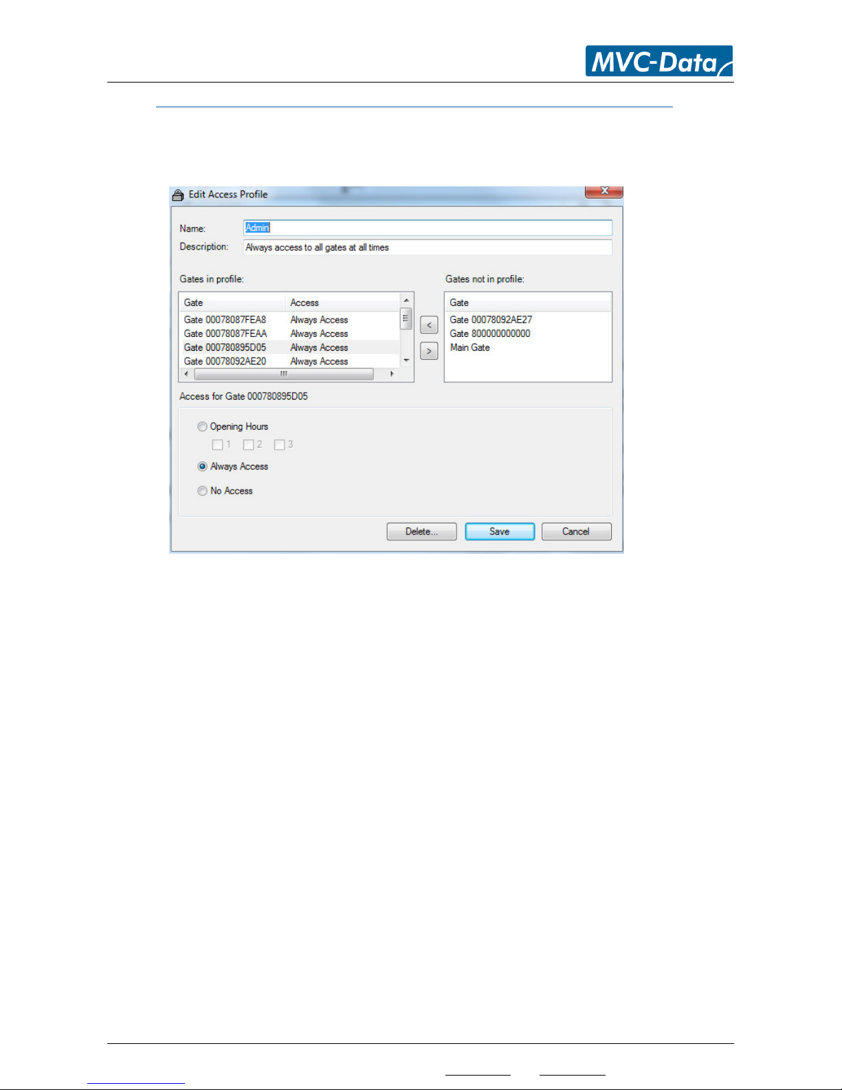
4.6.2 Edit or Delete a Access Profile – Menu “Settings” - > “Access” -> “Access Profiles”
This view shows an existing Access Profile menu. This menu can be open by clicking on an existing
Access Profile or by right clicking on the access profile in the drop down list in the graphical user
interface to the left.
Edit the access profile and click “Save” to store the changes or click “Delete” to remove the access
profile from the system.
Edit: Edit the access profile settings. Click “Save” when done to store the new settings
Delete: Click “Delete” to completely remove the access profile from the system
Caution!
It is highly recommended to remove an Access Profile from the users before deleting it.
Make sure that the users have another valid Access Profile
Cancel: Click “Cancel” to leave the menu without making any changes
Page 24
AccessZone® - PcManagement™ User Manual
All information is subject to change without notice. All other products and brand names are registered trademarks of their respective companies 2014-03-13 US 0.17
Copyright © 2005-2014 All rights reserved MVC-Data ApS Skalhuse 5 9240 Nibe Denmark Web www.mvc-data.com E-mail [email protected] Phone +45 25 12 84 02
24/47
4.7 Menu “Settings”-> “Program Settings”
This menu can be located in the main menu “Settings” “Program” or directly by activation of
(Ctrl-P)
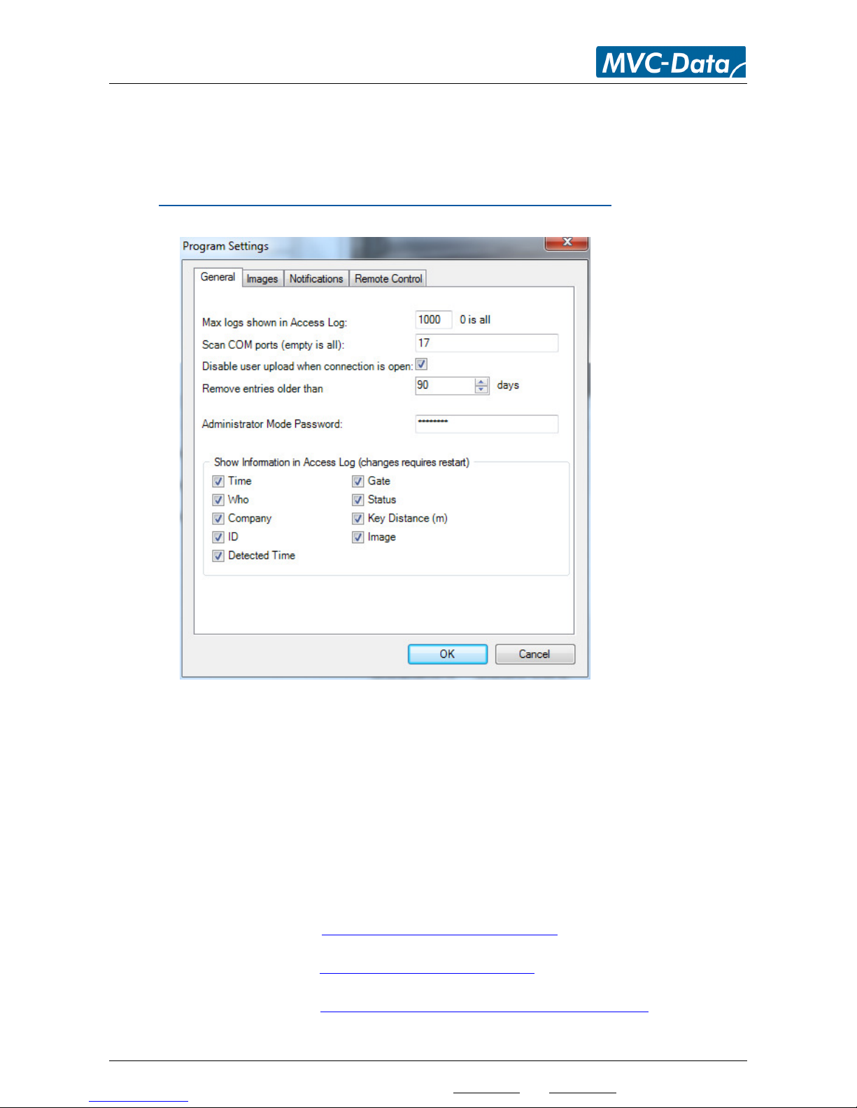
4.7.1 General Settings - Menu “Settings”-> “Program Settings” – “General”
Menu for the general system settings:
“Max logs shown in Access Log” specifies how many logs shown in the main screen. If set
to 10 only the 10 newest events are shown. All events are still stored in the database for
later analysis. Default is 1000
“Scan COM ports (empty is all)” specifies all the COM ports the system must search for a
GateController™. The list is ‘,’ (comma) separated. This is important if the PC running the
PcManagement™ system contains COM ports which are not connected to a
GateController™. E.g. COM port 2, 4, 6 and 8 is specified like this “2,4,6,8”. Default is empty
Note!
LAN/Wi-Fi and Bluetooth connected devices must also be mapped to a COM-port:
Bluetooth setup refer to: AccessZone Bluetooth Setup Manual
Lan setup refer to: AccessZone XPORT Setup Manual
Wi-Fi setup refer to:
AccessZone_GC3000_WiFi_Module_Setup_Manual
Page 25
AccessZone® - PcManagement™ User Manual
All information is subject to change without notice. All other products and brand names are registered trademarks of their respective companies 2014-03-13 US 0.17
Copyright © 2005-2014 All rights reserved MVC-Data ApS Skalhuse 5 9240 Nibe Denmark Web www.mvc-data.com E-mail [email protected] Phone +45 25 12 84 02
25/47
“Disable user upload when connection is open” to enable automatically upload of the user
database to the GateController™ when they connect. Default is disabled
“Remove entries older than” specifies how old the event log data are. I.e. when they will
be automatically deleted. Default is 90 days
”Administrator Mode Password” specify an administrator PIN code to be used when
starting the system. Max. up to 16 characters.
If PIN code is enabled:
PcManagement™ can only startup in ”administrator mode” if the PIN code is correct
entered.
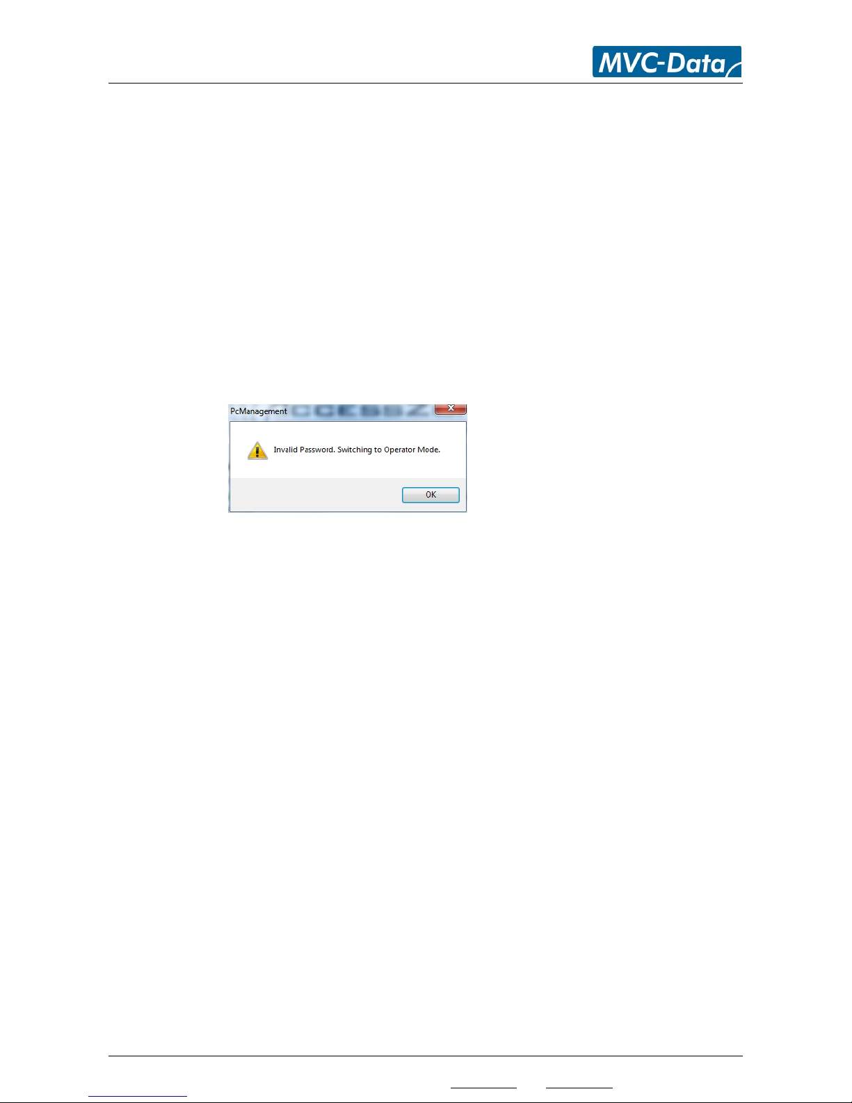
If the PIN code is not entered it starts up in “operator mode”. GateController™ and user
settings cannot be changed in ”operator mode” – Events can be viewed.
Erase the PIN code field to completely disable the administrator PIN code. I.e. it is
possible to startup in “administrator mode” without entering a PIN.
If PIN code is disabled:
PcManagement™ can be started up in either ”administrator mode” or ”operator mode”
depending on the choice made during startup.
“Show Information in Access Log” to enable/disable information shown in the main screen
window. E.g. if “Key Distance (m)” information is not important it can be hidden from the
main screen window for a simpler overview. Default is all enabled
Page 26
AccessZone® - PcManagement™ User Manual
All information is subject to change without notice. All other products and brand names are registered trademarks of their respective companies 2014-03-13 US 0.17
Copyright © 2005-2014 All rights reserved MVC-Data ApS Skalhuse 5 9240 Nibe Denmark Web www.mvc-data.com E-mail [email protected] Phone +45 25 12 84 02
26/47
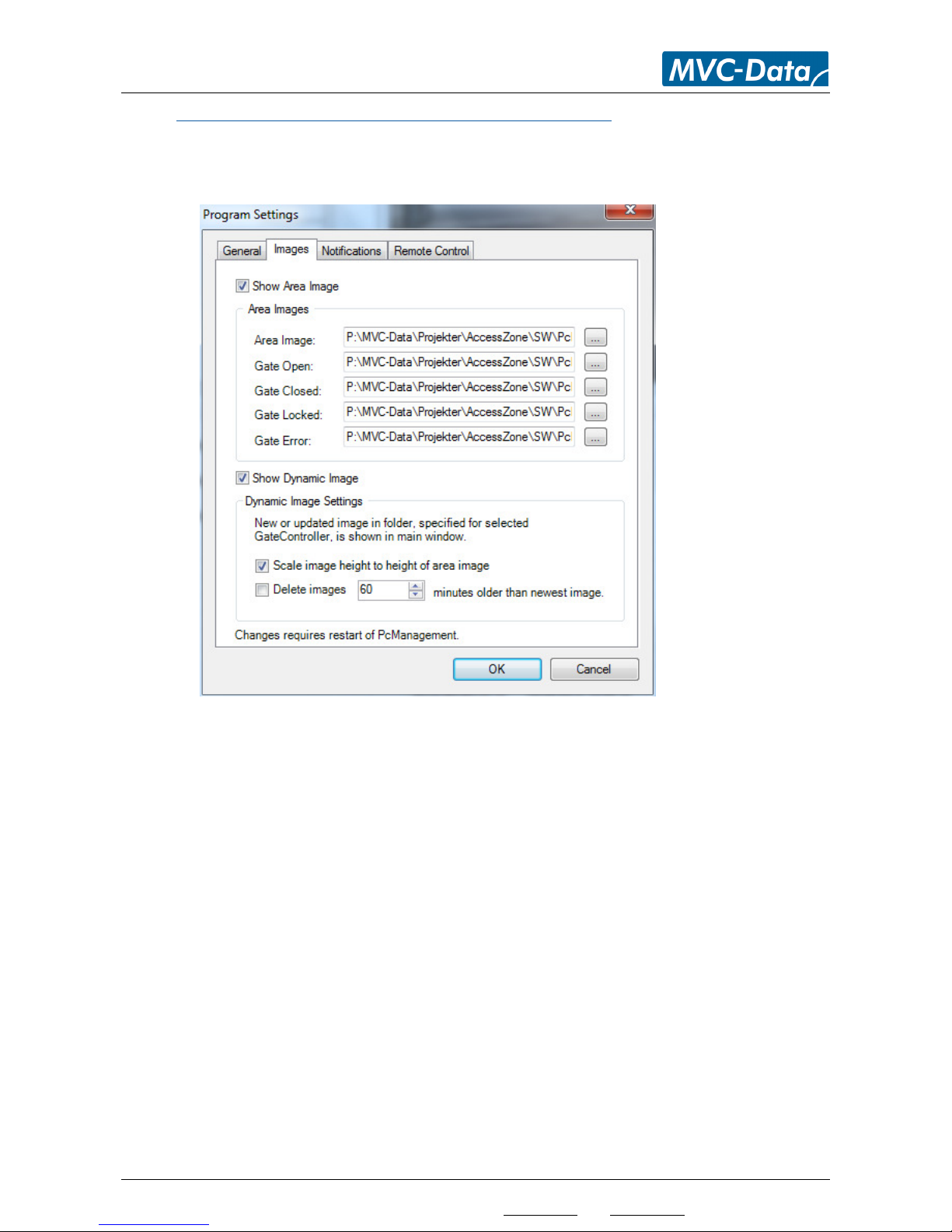
4.7.2 Images - Menu “Settings”-> “Program Settings” – “Imagesl”
Menu for specifying the different images to use as area image and a default door/barrier/gate
symbols for open, closed, locked and error state. The images are used as default and are used if
nothing else is specified for a GateController™:
“Show Area Image” select if you want a image (CAD drawing) shown of the secured area
“Show Dynamic Image” select if you want images from a surveillance camera shown to the
right of the area image. It can be freely selected from any folder on the PC or server. The
image is automatically updated and shows the latest image. Specify whatever the images
must be scaled to fit area image and if the images must be automatically deleted
TIP!
The shown image will be tagged with the access open event to make it easy to locate the image.
Click “OK” when done or click “Cancel” to leave without changes.
Page 27
AccessZone® - PcManagement™ User Manual
All information is subject to change without notice. All other products and brand names are registered trademarks of their respective companies 2014-03-13 US 0.17
Copyright © 2005-2014 All rights reserved MVC-Data ApS Skalhuse 5 9240 Nibe Denmark Web www.mvc-data.com E-mail [email protected] Phone +45 25 12 84 02
27/47
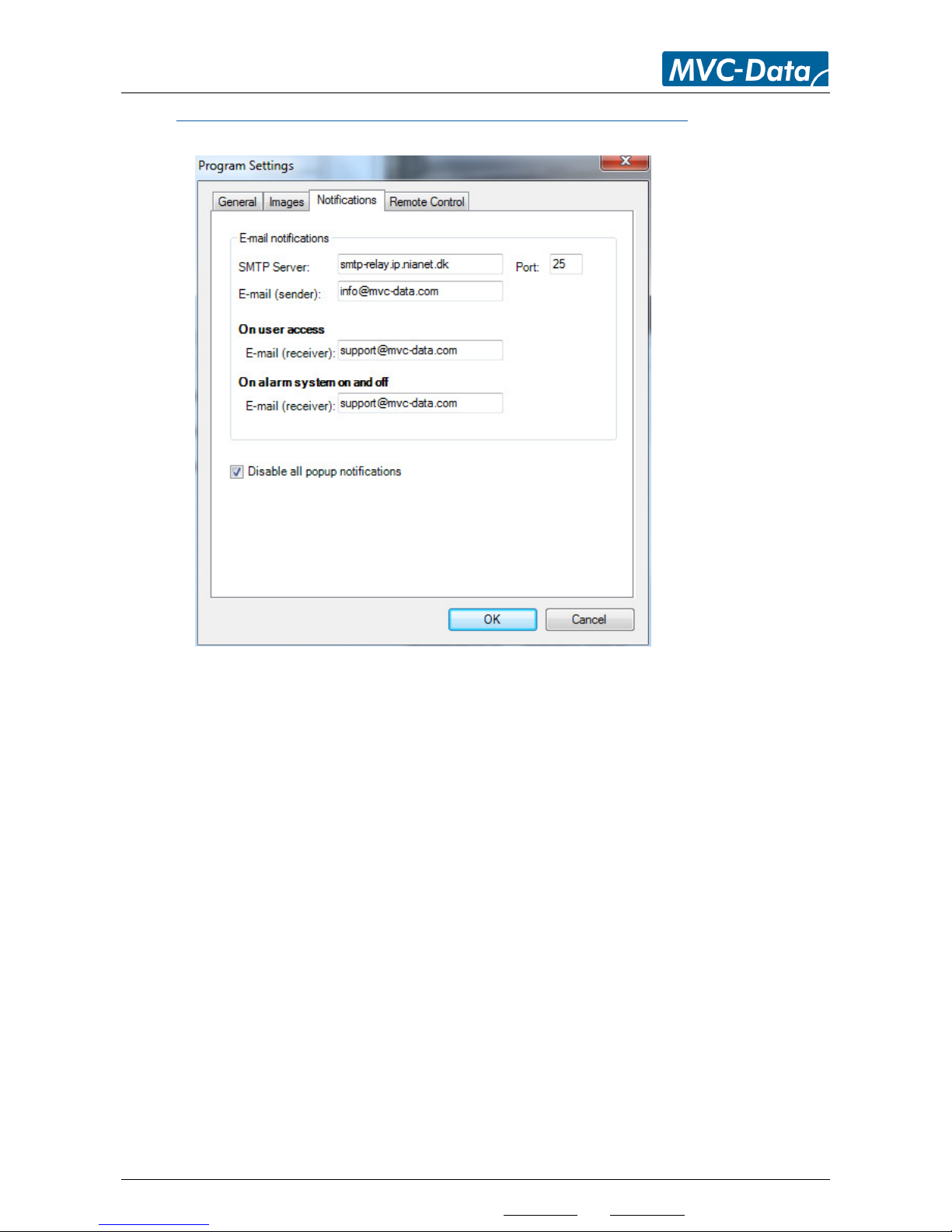
4.7.3 Notifications - Menu “Settings”-> “Program Settings” – “Notifications”
Menu for the general system email notifications setup:
Note!
The PC running PcManagement™ must have an internet connection to use this feature.
“SMTP Server” specify your SMTP server and port number (default is 25). The SMTP server
to use depends typically on the internet provider you have. Check your normal email
program or ask your network administrator
“E-mail (sender)” specifies the e-mail address to use as the sender for the e-mails
On user access
“E-mail (receiver)” specifies the e-mail address to send to on user access events
On alarm system on and off
“E-mail (receiver)” specifies the e-mail address to send to when the alarm is armed (on) or
disarmed (off)
“Disable all popup notifications” click field to disable the popup notifications
TIP!
The emails can be sent to an email-to-SMS service provider (gate way) to get the “email” sent as
an SMS instead.
Click “OK” when done or click “Cancel” to leave without changes.
Page 28
AccessZone® - PcManagement™ User Manual
All information is subject to change without notice. All other products and brand names are registered trademarks of their respective companies 2014-03-13 US 0.17
Copyright © 2005-2014 All rights reserved MVC-Data ApS Skalhuse 5 9240 Nibe Denmark Web www.mvc-data.com E-mail [email protected] Phone +45 25 12 84 02
28/47
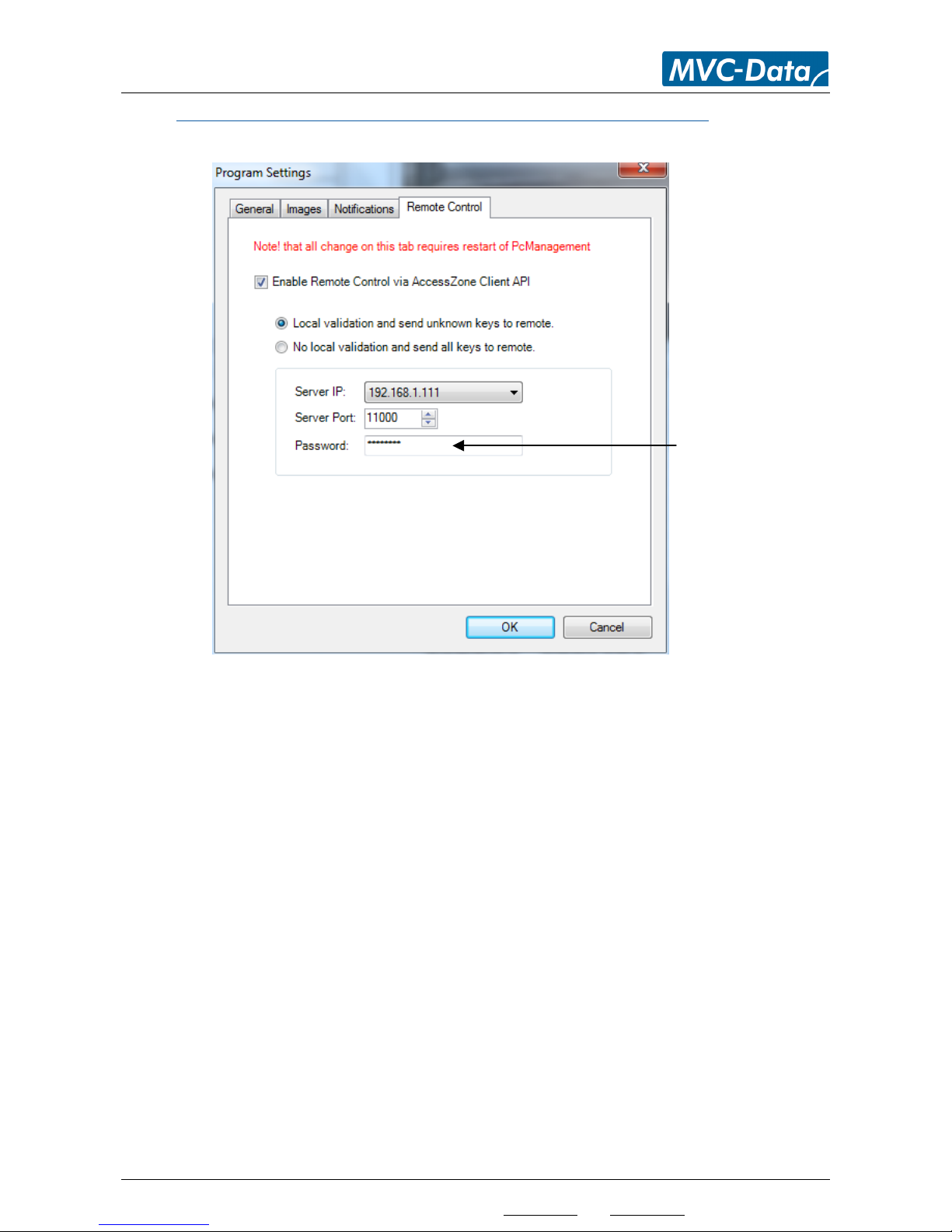
4.7.4 Notifications - Menu “Settings”-> “Program Settings” – “Remote Control”
Menu for the general system remote control setup:
The PC running PcManagement™ must have an internet connection to use this feature.
It is typically used with the “AccessZone Remote™” client application for remote monitoring and
control of the PcManagement server. However, you can implement your own client with the
AccessZoneClient.dll .Net component.
“Enable Remote Control via AccessZone Client API” specifies whatever you want to allow
remote control of your PcManagement server.
Validation Mode:
“Local validation and send unknown keys to remote” this option will first make a local
validation of the detected users (keys) and allow access if the detected user (key) are
valid.
Unknown users (keys) are sent to the remote client for validation.
“No local validation and send all keys to remote” with this option all detected users
(keys) are send to the remote client for validation. No local validation is performed.
Enter a unique 8-digit
login password for remote
client. E.g. 37282736
Page 29
AccessZone® - PcManagement™ User Manual
All information is subject to change without notice. All other products and brand names are registered trademarks of their respective companies 2014-03-13 US 0.17
Copyright © 2005-2014 All rights reserved MVC-Data ApS Skalhuse 5 9240 Nibe Denmark Web www.mvc-data.com E-mail [email protected] Phone +45 25 12 84 02
29/47
Network Settings:
“Server IP” the IP address of the PcManagement server. I.e. the PC’s IP address running
PcManagement server
“Server Port” the port address. Default 11000
“Password” a unique 8-digit login password. The same password must be applied on
the remote client side
Note!
PcManagement must be restarted to allow the changes to take effect.
All communication to remote client is encrypted for secure use.
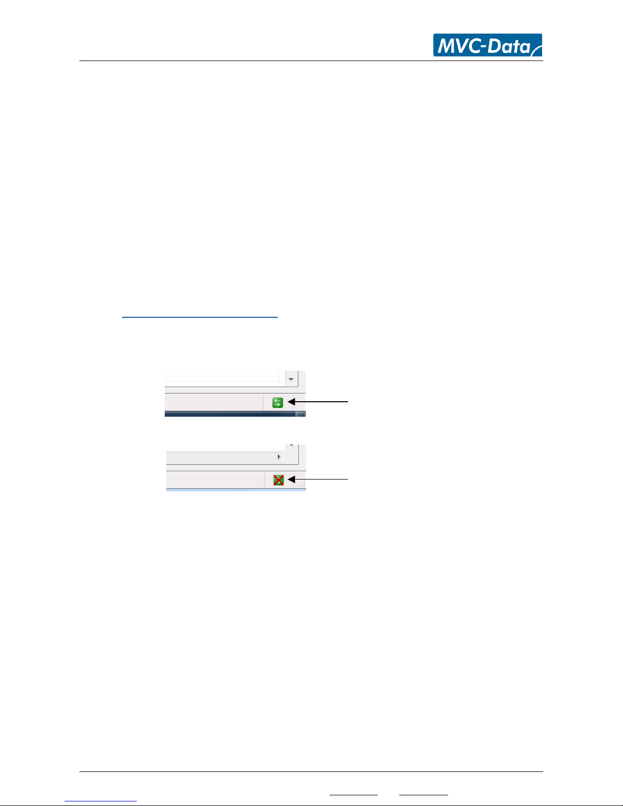
4.7.4.1 Remote Client Connection Status
It can always be monitored whatever a remote client is connected from the connection status
symbol on the main screen buttom right side.
A remote client is connected
No remote client is connected
Page 30
AccessZone® - PcManagement™ User Manual
All information is subject to change without notice. All other products and brand names are registered trademarks of their respective companies 2014-03-13 US 0.17
Copyright © 2005-2014 All rights reserved MVC-Data ApS Skalhuse 5 9240 Nibe Denmark Web www.mvc-data.com E-mail [email protected] Phone +45 25 12 84 02
30/47
4.8 GateController™ Settings –“Gates”
The GateController™ settings are unique for each GateController™ in the system. The menu can be
open by right clicking on the GateController™ in the list to the left or directly on the
door/barrier/gate symbol on the graphical user interface.
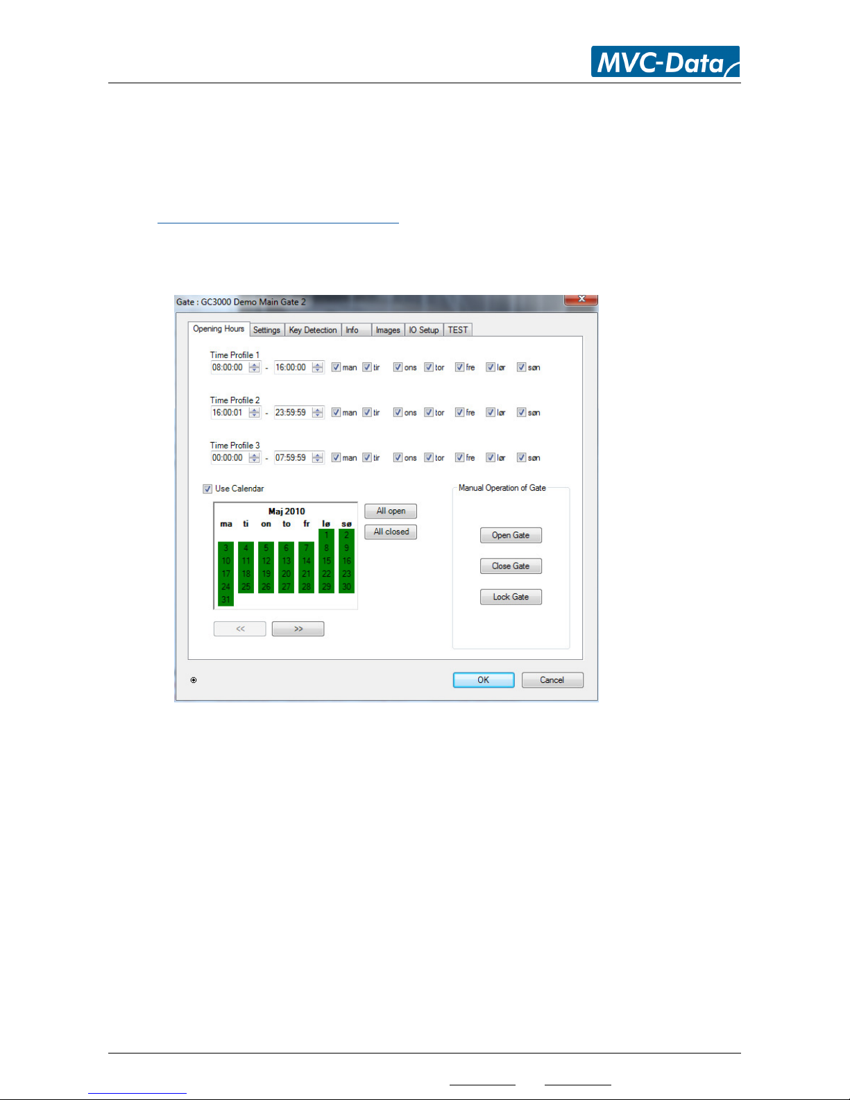
4.8.1 Time Profile - Menu “Opening Hours”
The image shows the menu to setup the opening hours for the GateController™. It is possible to
specify 3 different time profiles (intervals) and select which week days access is allowed. These
time and day profiles are used when creating the access profiles.
“Time Profile 1,2 & 3” sets the beginning and ending time and specify which week days the
time interval is valid for. The time intervals may overlap
“Use Calendar” is selected to enable the calendar function for that particular
GateController™. A green color means that access is allowed that day. Mark a date as
closed (Red) by clicking on the date. Click again to make the date an normal open day. Click
‘>>’ to go to the next month and ‘<<’ to go back again. It will always show current month
and one year ahead making it possible to set open and close days for one year at a time.
Note!
The “Use Calendar” option must also be enabled in all the user profiles to make this
function work. I.e. if either have this option disabled the feature is disabled. This allows
that some users run according to the calendar and others not.
“Manual Operation of Gate” is used to manually control the door or gate remote. Click
“Open Gate” to open the door/barrier/gate etc.
Page 31

AccessZone® - PcManagement™ User Manual
All information is subject to change without notice. All other products and brand names are registered trademarks of their respective companies 2014-03-13 US 0.17
Copyright © 2005-2014 All rights reserved MVC-Data ApS Skalhuse 5 9240 Nibe Denmark Web www.mvc-data.com E-mail [email protected] Phone +45 25 12 84 02
31/47
Caution!
The AccessZone® GateControllers with PC interface contain a (real time) clock and date. The
clock and date are automatically set and adjusted through the PC connection to
PcManagement™. As long as the PC is connected the clock and date are automatically adjusted.
However, if PcManagement™ is closed for a longer period of time the clock may drift a little –
the drift is coursed by small drifts in the internal clock frequency and is mainly influenced by
temperature variations and component tolerances. I.e. the clock should be updated on a regular
basis by reconnecting the GateController™ to PcManagement™.
Page 32
AccessZone® - PcManagement™ User Manual
All information is subject to change without notice. All other products and brand names are registered trademarks of their respective companies 2014-03-13 US 0.17
Copyright © 2005-2014 All rights reserved MVC-Data ApS Skalhuse 5 9240 Nibe Denmark Web www.mvc-data.com E-mail [email protected] Phone +45 25 12 84 02
32/47
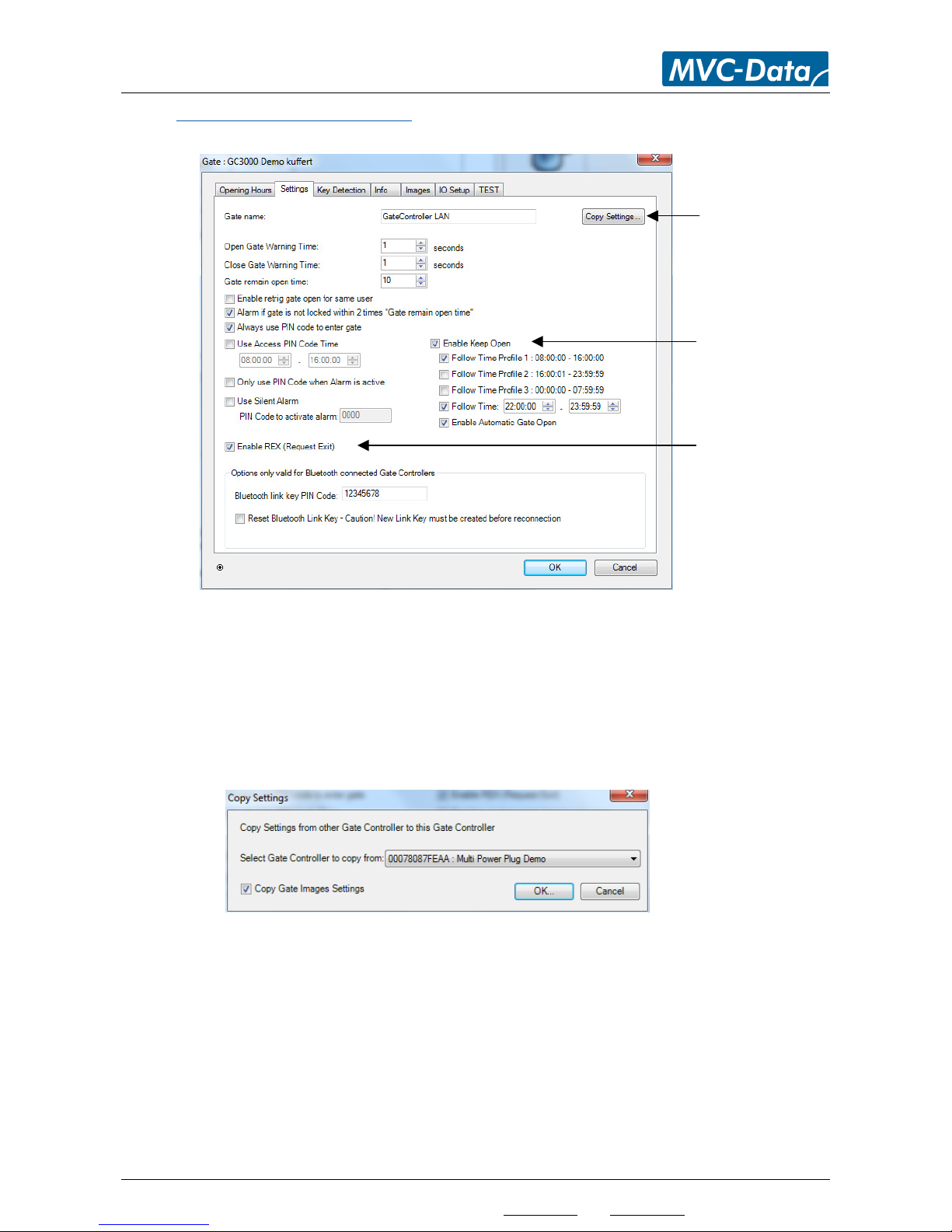
4.8.2 Gate Settings - Menu “Settings”
The image shows the menu for some operational settings for the GateController™:
“Gate name:” give the GateController™ a unique name for easy identification
TIP!
The GateControllers are sorted alphabetical in the main screen. Write a number in front of
the name to sort the GateControllers as you prefer ‘1’ for the first one etc.
“Copy Settings” option for copying the GateController™ settings from another
GateController™.
Select the GateController™ to copy settings from in the drop down list.
Click “OK” to copy the settings.
Note!
The GateController™ name and video folder (Menu “Images”) settings are not copied.
TIP!
Use this feature for easy setup of multiple doors and gates.
Easy copying of settings
from another gate
Settings for keep open
feature
Setting for enabling the
REX (Request Exit)
button feature
Page 33

AccessZone® - PcManagement™ User Manual
All information is subject to change without notice. All other products and brand names are registered trademarks of their respective companies 2014-03-13 US 0.17
Copyright © 2005-2014 All rights reserved MVC-Data ApS Skalhuse 5 9240 Nibe Denmark Web www.mvc-data.com E-mail [email protected] Phone +45 25 12 84 02
33/47
4.8.2.1 Gate Handling Options:
“Open Gate Warning Time” specified the number of seconds the buzzer must run before
opening the door/barrier/gate. ‘0’ seconds disables warning buzzer. Default is 2s
Note! Gate opening is delayed with the open warning time.
“Close Gate Warning Time” specified the number of seconds the buzzer must run before
closing the door/barrier/gate. ‘0’ seconds disables warning buzzer. Default is 2s
Note! Gate opening time is extended with the close warning time.
“Gate remain open time” the number of seconds the door/barrier/gate as a minimum is
kept open. I.e. the delay before closing the door/gate again. Default is 15s
Note! Gate opening time is delayed and/or extended with the open/close warning time.
”Enable retrig gate open for same user” to allow the gate to stay open as longs as the valid
user is detected.
Note! It is recommended to use “Gate remain open time” values above 10 seconds with
this feauture in RF noisy environments. I.e. heavy Bluetooth and Wifi activity.
”Alarm if gate is not locked within 2 x ”Gate remain open time” ” if selected the system will
generate an alarm if the door is not closed again as expected.
Note! The lock must support read-back of the lock state.
4.8.2.2 PIN Code Options:
“Always use PIN code to enter gate” is selected if an access PIN is required to enter the
door or gate. Access PIN must also be enabled for the users to be functional. I.e. both must
have this feature enabled. Default is enable.
“Use Access PIN Code Time” is selected if access PIN code is only required with the
specified time interval. E.g. this could be after normal working hours. Access PIN Code Time
must also be enabled for the users to be functional. I.e. both must have this feature
enabled. Default is disable.
“Only use PIN Code when Alarm is active” a comfort mode where the access PIN code is
only required if the alarm has been enabled. If another user has disabled the alarm by
entering the access PIN code the next user isn’t prompt for the access PIN code. Default is
disable.
This option requires that one of the PIN code options above have been selected.
“Use Silent Alarm” is selected to enable the silent alarm feature. A user can get access
when this code is entered 4 times or by 3 wrong PIN codes and then use this PIN code the
4th time. The door/gate is opened and an alarm is triggered and an event is sent to alert the
system administrator or security personal. Default is disable.
This option requires that one of the PIN code options above have been selected.
“Enable REX (Request Exit)” must be selected to allow use of the REX feature. Default is
disable.
Page 34
AccessZone® - PcManagement™ User Manual
All information is subject to change without notice. All other products and brand names are registered trademarks of their respective companies 2014-03-13 US 0.17
Copyright © 2005-2014 All rights reserved MVC-Data ApS Skalhuse 5 9240 Nibe Denmark Web www.mvc-data.com E-mail [email protected] Phone +45 25 12 84 02
34/47
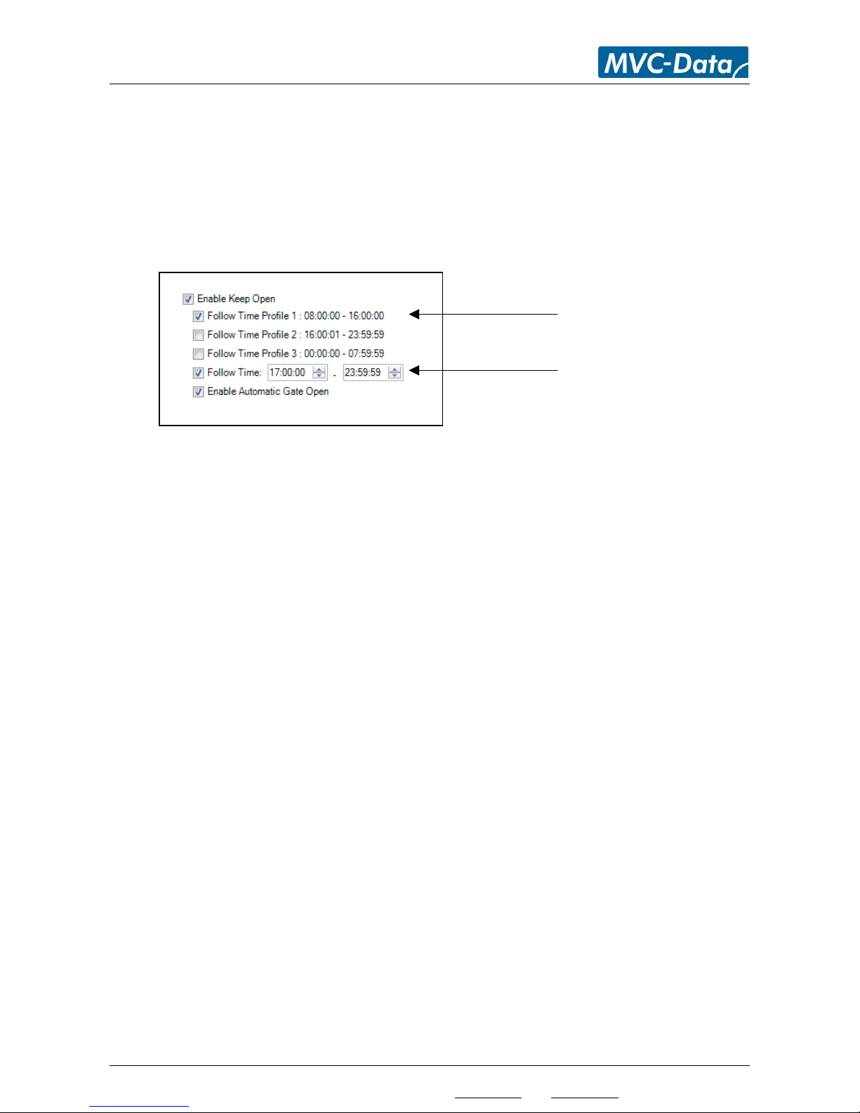
4.8.2.3 Keep Open option:
The keep open feature allows the GateController to work as an automatic door/barrier/gate
opener. It is well suited for access control to more public areas. It works after the specified time
interval either after access has been granted to valid user or full automaticly after the time
schedule specified.
Note!
The keep open feature follows the settings for weekday access and the system calendar.
“Enable Keep Open” specifies the time interval where the door/barrier/gate will be kept
open from and automatically closed again. Set a mark in the check box to enable feature.
o Select “Follow Time Profile 1” to use the same time interval as time profile 1
o Select “Follow Time Profile 2” to use the same time interval as time profile 2
o Select “Follow Time Profile 3” to use the same time interval as time profile 3
o Select “Follow Time” to specify a new additional time interval
Note! This setting does not have a weekday setting
The first valid user which is granted access will open the door/barrier/gate.
TIP!
Select any combination of the 4 keep open time intervals.
o Select “Enable Automatic Gate Open” to automatically open the door/barrier/gate at
the beginning of the specified time without any user intervention.
Note!
o “Follow Time Profile 1,2 and 3 are only supported by firmware versions:
• GC630/GC640/GC670 from version 2.03
GC3000 from version 1.96
• Older firmware versions only supports the “Follow Time” option but not the
“Enable Automatic Gate Open” feature.
o The “Use Access Keep Open Time” feature must also be enabled for the users to be
functional. I.e. both must have this feature enabled. Default is disable.
Time setting from Time Profiles
Additional t
ime setting
Page 35

AccessZone® - PcManagement™ User Manual
All information is subject to change without notice. All other products and brand names are registered trademarks of their respective companies 2014-03-13 US 0.17
Copyright © 2005-2014 All rights reserved MVC-Data ApS Skalhuse 5 9240 Nibe Denmark Web www.mvc-data.com E-mail [email protected] Phone +45 25 12 84 02
35/47
Options below are only valid for GateController™ using a Bluetooth PC interface:
“Bluetooth connection PIN Code” is the PIN code used when making the initial connection
to a PC (creating the Link Key). Default code is “12345678”
“Reset Bluetooth Link Key” set a mark in the check box and click “OK” button. The new PIN
Code is stored in the GateController™ and the current link key in the GateController™ is
reset.
Erase the link key on the PC before making a new connection with the new Bluetooth
connection PIN code from the PC. The check box is automatically cleared when clicking the
“OK” button.
TIP!
This is also useful if PcManagement™ must be moved to a new PC. Reset the Bluetooth
Link Key and install PcManagement™ on the new PC. Create a new link key from the new
PC.
The user data files: db.mdb and config.xml (typically stored in
c:\ProgramData\AccessZone\) can be copied to the same location on the new PC. I.e. all
your settings and users are moved to the new PC.
You can also copy these two files to a backup media for easy restoring of your system in
case of a PC break down etc.
Page 36
AccessZone® - PcManagement™ User Manual
All information is subject to change without notice. All other products and brand names are registered trademarks of their respective companies 2014-03-13 US 0.17
Copyright © 2005-2014 All rights reserved MVC-Data ApS Skalhuse 5 9240 Nibe Denmark Web www.mvc-data.com E-mail [email protected] Phone +45 25 12 84 02
36/47
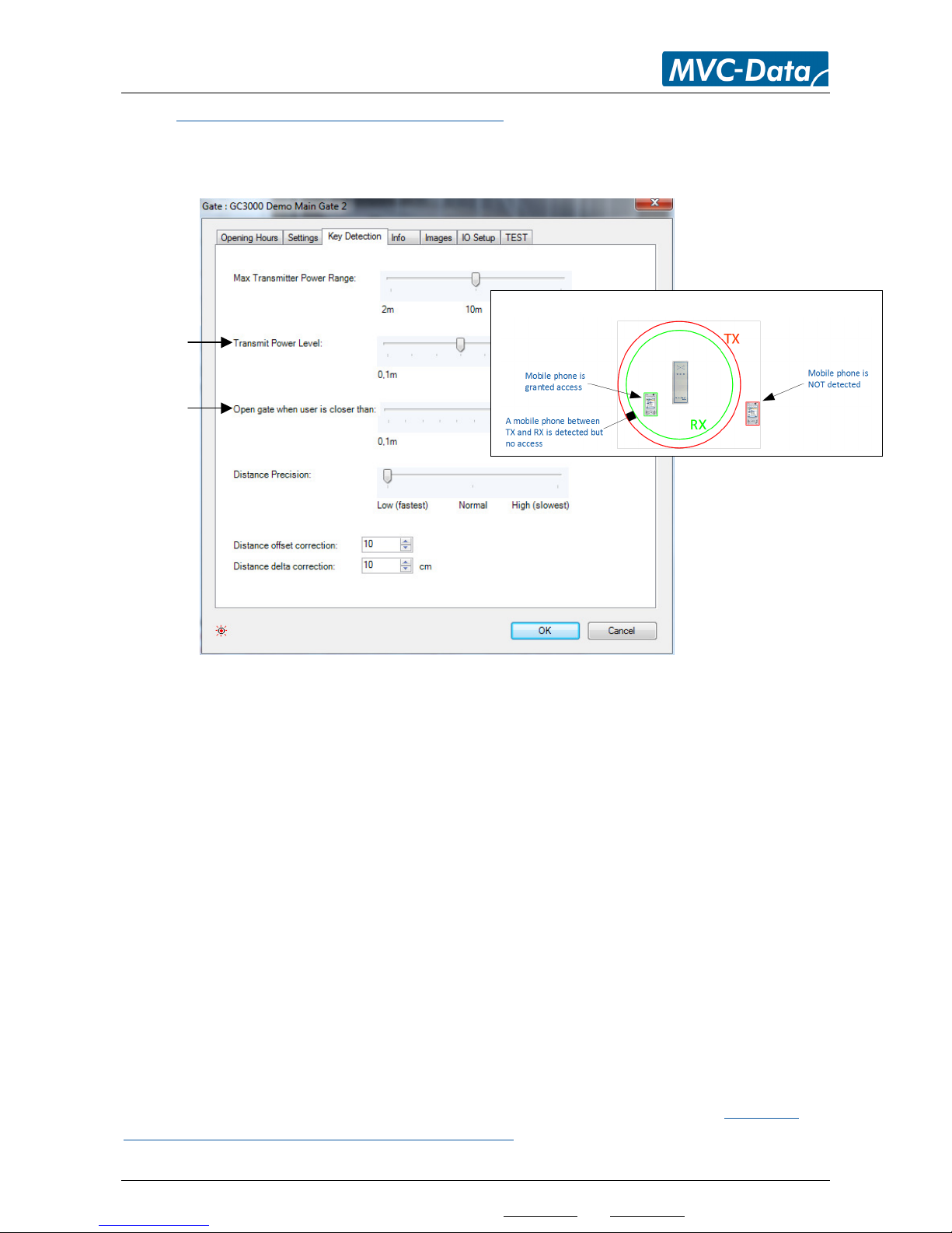
4.8.3 Key Detection Range - Menu “Key Detection”
This menu allows you to adjust the user key (SBD key) detections parameters. What range
(transmitting power) should be used with the GateController™, the distance measurement and the
distance accuracy can be adjusted to the desired level for each door/barrier/gate:
“Max Transmitter Power Range” sets the transmitter power (TX) to the desired maximum
range. Click “OK”. Reconnect GateController™ for the new power settings to take effect.
Right click the GateController™ in the list and click “Restart Gate Controller”. Default is
10m
“Transmit Power Level” selects the used TX power level within the selected power range.
Default is 10m
“Open gate when user is closer than” specifies the detection level (RX) for the users. I.e.
how close must the user be to the GateController™ before access can be granted. There
are 100 levels to choose from to make individual adjustments. Default is ~0,5m
TIP!
Start with a large value and go down until detection is not possible anymore from the desired
distance. Then go one step up again to find the correct values for the installation.
Caution!
The detection range can be influenced by the surroundings. If the detection range is not as
expected the values can be adjusted up/down to find a suitable set of values. Please test and
adjust as appropriate on location.
Note! The detection range may differ depending on the used device. Refer to 4.5.1 Add a new
User – Menu “Settings” - > “Access” -> “Users”-> “Add” on how to compensate each user
individually.
Relation between TX and RX
TX level
RX level
Page 37
AccessZone® - PcManagement™ User Manual
All information is subject to change without notice. All other products and brand names are registered trademarks of their respective companies 2014-03-13 US 0.17
Copyright © 2005-2014 All rights reserved MVC-Data ApS Skalhuse 5 9240 Nibe Denmark Web www.mvc-data.com E-mail [email protected] Phone +45 25 12 84 02
37/47
4.8.3.1 How to understand TX and RX parameters
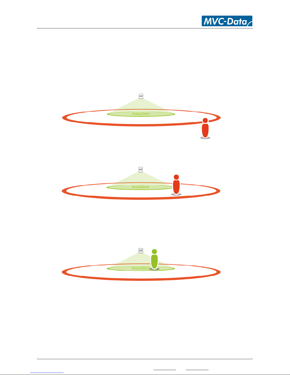
The TX – and RX range should ideally lie on the same circle. It is recommended that the TX range is
a little larger than the RX range.
Scenario 1:
The user is outside the TX – and RX range and the user is not detected by the AccessZone® system.
I.e. no access allowed
Scenario 2:
The user is now inside the TX circle and the AccessZone® system can read the unique ID from the
mobile phone. However, access is not allowed because the user is outside the RX range.
Scenario 3:
The user is now inside the TX circle and the AccessZone® system can read the unique ID from the
mobile phone. The user is also within the RX range and access are allowed.
Page 38
AccessZone® - PcManagement™ User Manual
All information is subject to change without notice. All other products and brand names are registered trademarks of their respective companies 2014-03-13 US 0.17
Copyright © 2005-2014 All rights reserved MVC-Data ApS Skalhuse 5 9240 Nibe Denmark Web www.mvc-data.com E-mail [email protected] Phone +45 25 12 84 02
38/47
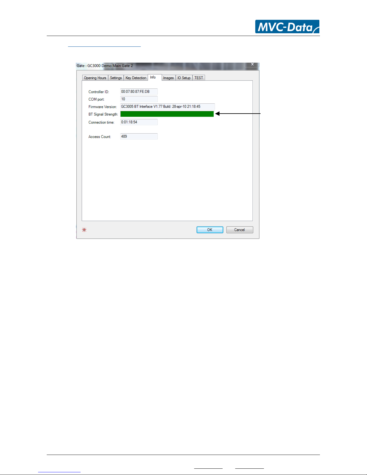
4.8.4 System Info - Menu “Info”
The image shows specific information for the selected GateController™:
“Controller ID” shows the connected GateController™ ID (the unique Bluetooth BD
address)
“COM port:” shows the COM port number for the connected GateController™
“Firmware Version” shows the current firmware version in the GateController™
“BT Signal Strength” shows a bar with the signal strength of the connection between the
GateController™ and the PC. The signal strength is constantly monitored locally in the
GateController™ and reported back.
Note!
This value is only of interest for GateControllers with a Bluetooth PC interface. If the signal
strength is too weak it will automatically close the connection and try to reconnect to the
GateController™
”Connection time” shows how long time the PC and GateController™ has been connected
“Access Count” show the total number of granted accesses on the door/barrier/gate.
TIP!
This parameter can be used to schedule door/barrier/gate maintenance.
Only valid for systems with
a Bluetooth PC interface
Page 39
AccessZone® - PcManagement™ User Manual
All information is subject to change without notice. All other products and brand names are registered trademarks of their respective companies 2014-03-13 US 0.17
Copyright © 2005-2014 All rights reserved MVC-Data ApS Skalhuse 5 9240 Nibe Denmark Web www.mvc-data.com E-mail [email protected] Phone +45 25 12 84 02
39/47
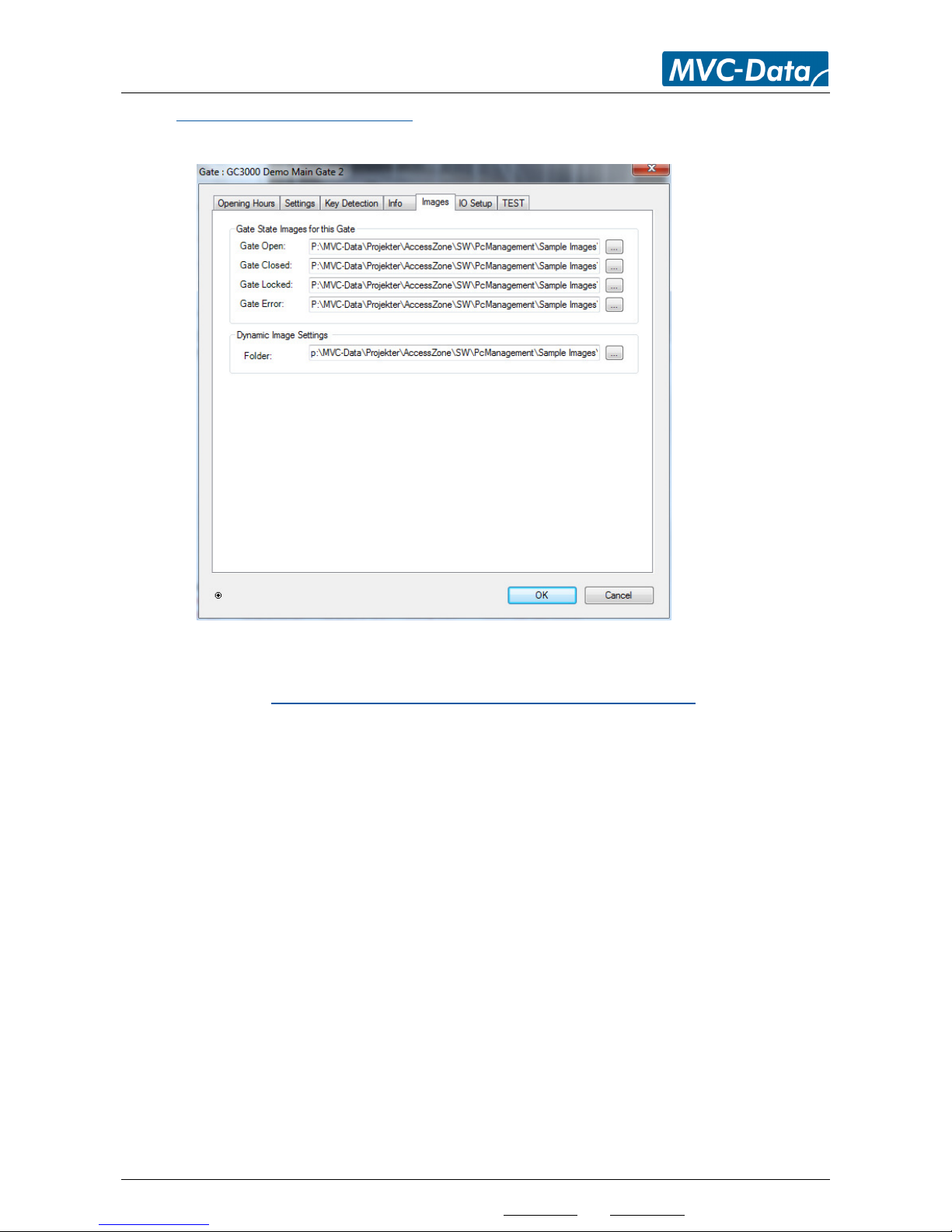
4.8.5 System Images - Menu “Images”
This image shows the used images for the specific GateController™:
“Gate State Images for this Gate” select the door/barrier/gate symbols to use with that
particular GateController™. If nothing is specified the default images will be used. See
section 4.7.2 Images - Menu “Settings”-> “Program Settings” – “Imagesl”
“Dynamic Image Settings” specify the path to the images from the surveillance camera to
be shown to the left of the CAD drawing of the secured area
TIP!
You can design your own symbols. Save the symbols in jpeg format and in the correct size
matching the customized image (CAD drawing) of the secured area. You can also select some of
the default delivered symbols (typically c:\Program Files\MVC-Data\AccessZone\Sample Images\..)
Page 40
AccessZone® - PcManagement™ User Manual
All information is subject to change without notice. All other products and brand names are registered trademarks of their respective companies 2014-03-13 US 0.17
Copyright © 2005-2014 All rights reserved MVC-Data ApS Skalhuse 5 9240 Nibe Denmark Web www.mvc-data.com E-mail [email protected] Phone +45 25 12 84 02
40/47
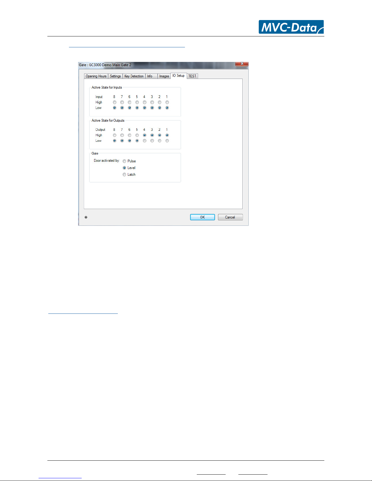
4.8.6 Input/Output Settings - Menu “IO Setup”
This view shows the Input/Output specific information for the selected GateController™:
“Active State for Inputs” set the active levels (invert) for all inputs. The system can with this
feature adapt to almost all sensors. Changes will take effect immediately.
Default is input 1, 2, 3 and 4 set as low active.
“Active State for Outputs” set the active levels (invert) for all outputs. The system can with
this feature adapt to almost all kinds of door/barrier/gate logic. Changes will take effect on
next event.
Default is output 1, 2, 3 and 4 set as high active.
Default System Settings:
GC630/GC640/GC670:
Inputs: 1, 2, 3 and 4 are high active and 5, 6, 7, 8 are not used (don't care)
Output: 1 and 2 are high active and 3, 4, 5, 6, 7, 8 are not used (don't care)
GC3000 before firmware V2.78:
Inputs: 1, 2, 3 and 4 are low active and 5, 6, 7, 8 are not used (don't care)
Output: 1, 2, 3 and 4 are high active and 5, 6, 7 and 8 are low active
GC3000 from firmware V2.78:
Inputs: 1, 2, 3 and 4 are high active and 5, 6, 7, 8 are not used (don't care)
Output: 1, 2, 3 and 4 are high active and 5, 6, 7 and 8 are low active
All systems do not have all 8 inputs and outputs. Please refer to the appropriate Installation
Manuel to see the number of I/Os for your system.
Caution!
Caution must be taken when changing the I/O parameters
Page 41

AccessZone® - PcManagement™ User Manual
All information is subject to change without notice. All other products and brand names are registered trademarks of their respective companies 2014-03-13 US 0.17
Copyright © 2005-2014 All rights reserved MVC-Data ApS Skalhuse 5 9240 Nibe Denmark Web www.mvc-data.com E-mail [email protected] Phone +45 25 12 84 02
41/47
“Gate” specifies how the door/barrier/gate is activated:
It supports 3 different door/gate output types to support different door/gate mechanisms.
All types can be combined with a warning buzzer period before gate activation (warning
buzzer can also be switched off)
“Pulse”
A 1 second pulse is used to activate the gate and another 1 second pulse is used to close
the gate again after the timeout of the “Remain gate open time” period.
Remain open time
Door/Gate Output _____|¯¯¯|______________________|¯¯¯|___
Warning open time with buzzer Warning close time with buzzer
“Level”
A pulse is used to activate the gate. The length of the pulse depends on the “Remain gate
open time” period or if “Keep Open” feature is enabled and active.
Remain open time
Door/Gate Output _____|¯¯¯¯¯¯¯¯¯¯¯¯¯¯¯¯¯¯¯¯¯¯¯¯¯¯|___
Warning open time with buzzer Warning close time with buzzer
“Latched” (toggle)
The output is kept active (ON) from one valid access to the next where it changes back
(toggle).
Door/Gate Output _____|¯¯¯¯¯¯ .……………….. ¯¯¯¯¯¯|___
Warning open time with buzzer Warning close time with buzzer
Select the type suitable for your door, barrier or gate. Please refer to the door/barrier/gate
manual for how to control it.
TIP!
A barrier and a gate is usually a “Pulse” type. However, some barriers and gates have a
built-in close timer. Use the “Level” type with a 1 s “Gate remain open time” to get a
single open pulse.
A normal entry door with a door strike is usually a “Level” type.
Latch (toggle) can be used with both doors/barriers/gates. It is recommended to use a
user access PIN code with this type of signal. Specail care must be taken when using the
latched mode with the alarm arming procedure. Refer to 8.1.2 Alarm Arming and
Disarming
The open signal can be inverted by changing the I/O settings. Refer to Input/Output
Settings - Menu “IO Setup”
Page 42
AccessZone® - PcManagement™ User Manual
All information is subject to change without notice. All other products and brand names are registered trademarks of their respective companies 2014-03-13 US 0.17
Copyright © 2005-2014 All rights reserved MVC-Data ApS Skalhuse 5 9240 Nibe Denmark Web www.mvc-data.com E-mail [email protected] Phone +45 25 12 84 02
42/47
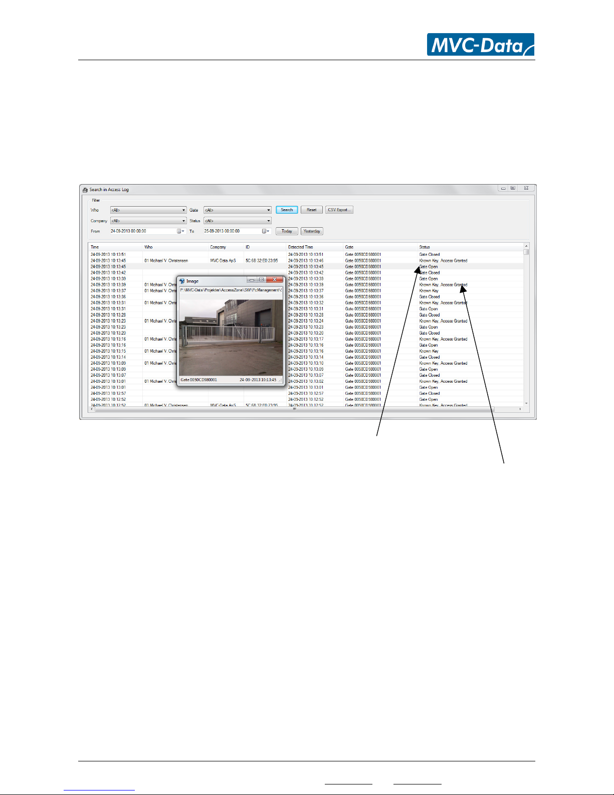
4.9 Database Search Tool – Menu “Search” -> “Access Log”
The tool is started from the main menu “Search” and “Access Log” or by pressing F3
This view shows how to make advanced searches in the event log database.
In example: Look for granted access for a particular user. All accesses on a particular
door/barrier/gate or all accesses done from user from a specific Company (or other additional
information added). Set the desired filters to narrow down the search results.
Click on the "Gate Open" to get the picture from the camera when the gate was opened.
Click on the "Known Key, Access Granted" to open the registered picture from the known user.
“Who” select a specific user from the list
“Gate” select a specific gate from the list
“Company” select a specific company from the list
“Status” select a specific event from the list
“Today” get all the event from today
“Yesterday” get all the event from yesterday
Click “Search” to start a search or click “Reset” to reset filters
TIP!
The “From” and “To” filters can be set to any date range or set down to a timer interval in
seconds. Select the days from the calendar.
Page 43
AccessZone® - PcManagement™ User Manual
All information is subject to change without notice. All other products and brand names are registered trademarks of their respective companies 2014-03-13 US 0.17
Copyright © 2005-2014 All rights reserved MVC-Data ApS Skalhuse 5 9240 Nibe Denmark Web www.mvc-data.com E-mail [email protected] Phone +45 25 12 84 02
43/47
4.10 Tools – Menu “Tools”
The tools menu contains two tools “Firmware Upload” and “Replace Gate Controller”.
4.10.1 Firmware Upload Tool - Menu “Tools”-> “Firmware Upload”
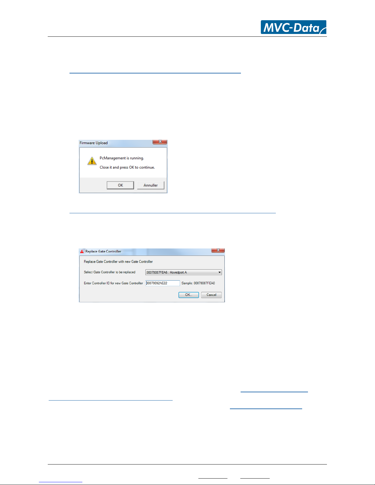
The “Firmware Upload” tool can be started from PcManagement™ or directly from the Windows
installation menu “Programs”. The tool can upload new firmware to the connected
GateControllers. Refer to the “Firmware Upload User Manaul”.
Note!
PcManagement™ must be closed to release the used COM ports. The system will automatically
start a dialog:
4.10.2 Replace GateController Tool - Menu “Tools”-> “Replace Gate Controller”
The “Replace Gate Controller” tool makes it easy to exchange a GateController™. I.e. all the
settings and profiles are copied to the new GateController™ and the old GateController™ can be
deleted.
“Select Gate Controller to be replaced” select an existing GateController™ from the drop
down list
“Enter Controller ID for new Gate Controller” enter the ID of the new GateController™. The
GateController™ ID must not existing in the system
TIP!
The GateController™ ID can be found by connecting the system to PcManagement™.
Add the COM port number if not used before. Refer to section 4.7.1 General Settings - Menu
“Settings”-> “Program Settings” – “General”. The system will automatically detect it as a new
GateController™ and add it to the system. Refer to section 4.8.4 System Info - Menu “Info” for how
to read the ID.
Delete the GateController™ again to allow settings to be copied.
The new GateController™ can be connected to the system when the settings have been copied.
Page 44

AccessZone® - PcManagement™ User Manual
All information is subject to change without notice. All other products and brand names are registered trademarks of their respective companies 2014-03-13 US 0.17
Copyright © 2005-2014 All rights reserved MVC-Data ApS Skalhuse 5 9240 Nibe Denmark Web www.mvc-data.com E-mail [email protected] Phone +45 25 12 84 02
44/47
5 Mobile Phone as Access Key
Any Bluetooth enabled mobile phone can be used as access key. No software has to be installed
on the mobile phone. Please refer to MVC-Data “How to Get the Bluetooth ID” paper
(http://www.mvc-data.com/Misc.html).
MVC-Data ApS has developed some smart phones apps for iPhone and Android platform. Please
refer to: http://www.mvc-data.com/Smart_Phones.html
The system will detect the mobile phone when it comes within the specified detection range.
TIP!
No pairing or search for devices must be active on the used mobile phone.
Steps:
1) Enable Bluetooth on mobile phone and set it to visible. Refer to the mobile phone's User
Manual
2) Enter the 4 digit access PIN code when prompt (If PIN code is required) and click ”OK”
Note!
The time (Bluetooth inquiry scan time) a mobile phone uses to scan for other Bluetooth devices,
that want to connect to it, is typically set to a low value to preserve battery power. I.e. the time to
discover a nearby Bluetooth enabled mobile phone strongly depends on implementation details
for a particular mobile phone.
6 GPS Antenna as Access Key
A Bluetooth GPS antenna is also suitable as a simple wireless key. It works fine with and without
PIN code. The PIN is typically fixed to "0000" or "1234" so the PIN code can typically be left out.
I.e. enable the GPS antenna without requiring PIN code.
The GPS antenna must typically not have an active connection to another Bluetooth device.
Note!
Most battery powered devices will automatically switch off after ex. 60 minutes to preserve
battery power.
7 AccessZone® Bluetooth Tags
The AccessZone® Bluetooth Tags GC100 and GC230 are suitable as a simple wireless key. They
work without PIN code. GC230 is also available with a fixed 4 digit PIN code.
They are available as battery powered hand-held devices (GC100) or as power wired devices for
mounting on cars/trucks or wheelchairs (GC230).
Please refer to
http://www.mvc-data.com/TAG.html for more information.
Page 45

AccessZone® - PcManagement™ User Manual
All information is subject to change without notice. All other products and brand names are registered trademarks of their respective companies 2014-03-13 US 0.17
Copyright © 2005-2014 All rights reserved MVC-Data ApS Skalhuse 5 9240 Nibe Denmark Web www.mvc-data.com E-mail [email protected] Phone +45 25 12 84 02
45/47
8 External Buttons
This section describes how the external buttons are used.
Please refer to the Installation Manual for how to connect external buttons as the REX push
button and blocking operation sensors to the GateControllers.
8.1 Request Exit – REX Push Button
8.1.1 Request Exit
An external REX push button can be connected to the system. The REX push button must be
installed on the secured side and will allow easy exit without using a mobile (except in the case of
arming the alarm system).
The REX push button is also used with the Alarm Arming and Disarming feature.
The system will log all exits made with the REX push button.
8.1.2 Alarm Arming and Disarming
The system can arm and disarm an alarm system. The output is a level/latched output and the
signal can be inverted.
The REX push button is also used with this feature.
8.1.3 Disarming the Alarm
The system will disarm the alarm by activating the output when a valid user has been detected.
The alarm is kept disarmed until armed again.
8.1.4 Arming the Alarm
The system will arm the alarm again when a valid user has been detected and the user presses the
REX push button.
The alarm is kept armed until a valid user disarms it again.
TIP!
Special care must be taken if the latched output is used for door activation. In this mode the door
is already open (latched) when the alarm is going to be armed. The user must push the REX button
before showing the user ID (mobile phone). This must be done within the remain open time period
from the REX button was pressed be course the REX event is cleared after time-out of the remain
open time period.
A suitable value for remain open time is 5-10 seconds for latched mode.
Page 46
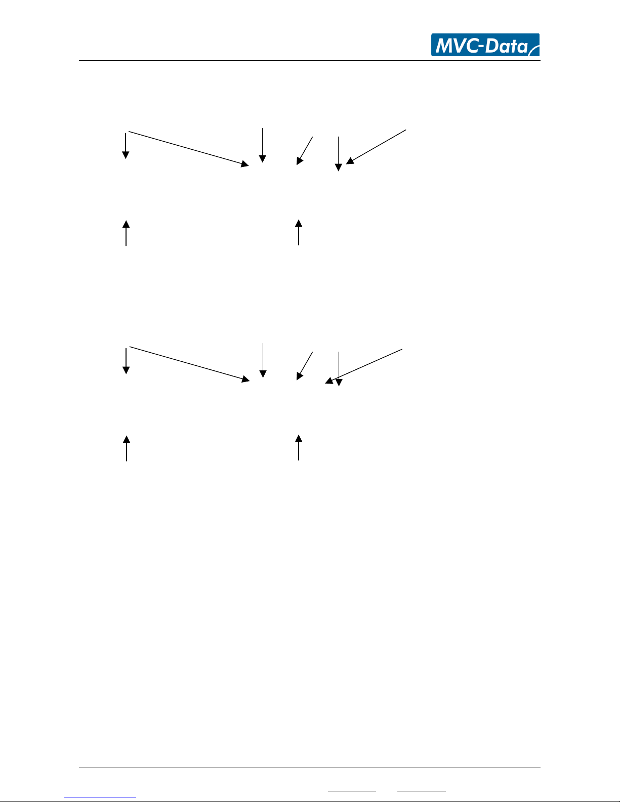
AccessZone® - PcManagement™ User Manual
All information is subject to change without notice. All other products and brand names are registered trademarks of their respective companies 2014-03-13 US 0.17
Copyright © 2005-2014 All rights reserved MVC-Data ApS Skalhuse 5 9240 Nibe Denmark Web www.mvc-data.com E-mail [email protected] Phone +45 25 12 84 02
46/47
8.2 Timing Diagram of the outputs – Normal Access and Arming the Alarm
Case with active high outputs shown
Gate _||___________||______||____
Alarm _||_________________
8.3 Timing Diagram of the Outputs – Normal Access and Reject Arming of the Alarm
Case with active high outputs shown
Gate _||___________||__________________
Alarm _||___|
Normal user access with
PIN code with gate
activation
Alarm is disarmed
User also pushes the REX
key to arm the alarm
10 s reject alarm arming
period with active buzzer
Start Stop
Alarm is armed
User pushes the REX key
again to exit the gate
Normal user access with
PIN code with gate
activation
User pushes the REX key
again to reject arming of
the alarm
Alarm is disarmed
User also pushes the REX
key to arm the alarm
10 s reject alarm arming
period with active buzzer
Start Stop
Alarm is armed
Page 47
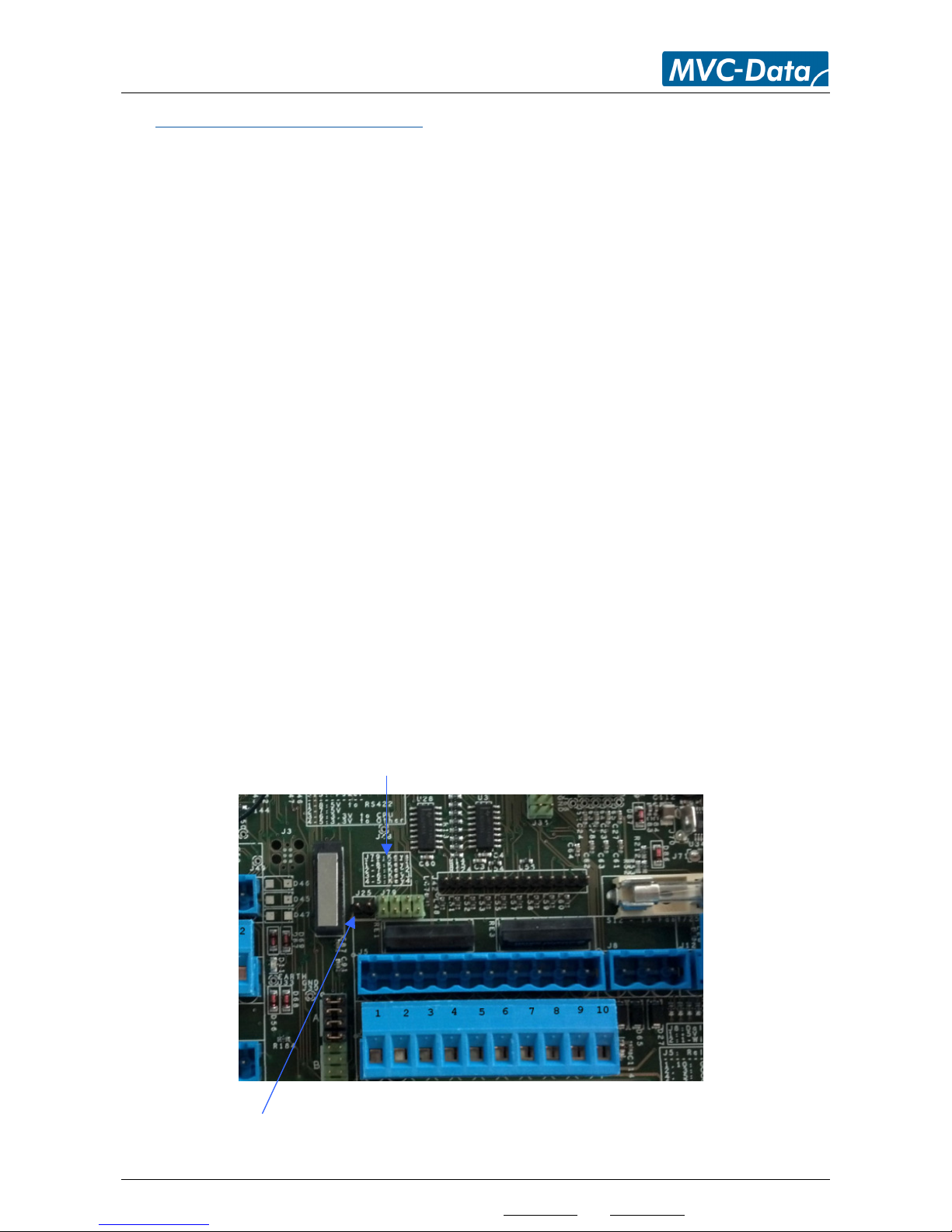
AccessZone® - PcManagement™ User Manual
All information is subject to change without notice. All other products and brand names are registered trademarks of their respective companies 2014-03-13 US 0.17
Copyright © 2005-2014 All rights reserved MVC-Data ApS Skalhuse 5 9240 Nibe Denmark Web www.mvc-data.com E-mail [email protected] Phone +45 25 12 84 02
47/47
9 Default Factory System Settings
9.1 GC630/GC640 Series
The system configuration settings can be restored to factory settings:
Please follow the below steps:
Power off the device
Short the 4 RS422 signals:
o TxA to RxA
o TxB to RxB
Power on the device – Wait - a short beep acknowledges that the factory settings have
been restored
Power off the device again
Reconnect the 4 RS422 signals
Device can safely be re-powered with the restored factory settings.
Caution!
General caution must be taken when working with the wires to avoid short circuits etc.
9.2 GC3000 Series
Please follow the below steps:
Power off the device
Open the box
Short the PIN 2-7 in J79 (it has no run-time functionality)
Power on the device – Wait - a short beep acknowledges that the factory settings have
been restored
Power off the device again
Remove the short the PIN 2-7 in J79 again
Device can safely be re-powered with the restored factory settings
TIP!
Add a jumper on J25 to avoid tamper alarm - remember to remove the jumper again.
 Loading...