

Muza GP300 Instruction Manual
Instruction Manual

Introduction
Important Notes
Power Supply
Handling and Transporting
Location
Before connection, please ensure all power
devices such as amplifiers must first be
turned off, in order to avoid any damages.
Avoid using this unit together with
same circuit of electronic products that
will generate line noises.
If an AC adapter is used, it should be
unplugged from the AC outlet if the
instrument is not to be used for an
extended period of time.
Unplug the AC adapter during electric
storms.
Do not place this unit too close to heat
sources such as radiators and amplifiers
in order to prevent damages like
interference.
Do not expose this unit under excessive
sunlight, water and moisture.
Strong vibration and shocks will damage
this unit.
Clean this unit with a soft and dry cloth.
A slightly dampened cloth with mild
detergent might remove stubborn dirt.
Never use thinners and alcohol for
cleaning the unit.
Grab the unit firmly while unplugging
the cables, never pull the audio cables
with stress.
Disconnect all cables before moving the
instrument.
Physical shocks caused by dropping ,
bumping the instrument, or placing
heavy objects on top of it, can result in
scratches and even more severe damages.
Never apply excessive force to the
controls, connectors or other parts of
the instrument.
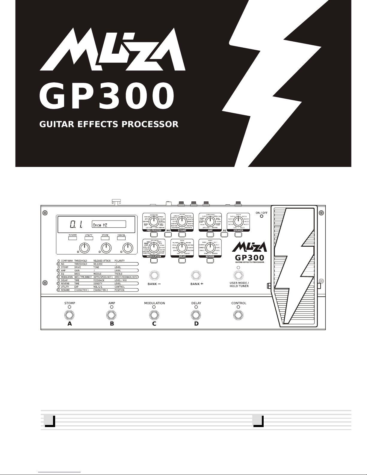
Thank you very much for purchasing this Guitar Effects Processor. This processor is
designed for you with a variety of wonderful guitar voices including distortion, wahwah,
delay, compressor, EQ, reverb, amp simulation, speaker simulation and more.
You can create your own voices easily and conveniently through the user-friendly interface
and parameter adjustment functions.
You are recommended to study this manual carefully before using the unit.
Cleaning
2
Main Features
Super user-friendly operation.
60 user patches and 60 default settings.
Foot switches for easy patch changing and other operations.
Excellent simulation of 11 famous Stomps, 11 Amplifiers as well as 5
professional pedal tones.
Delay's hold function with 4000 ms times delay.
11 effects for serial use.
Excellent tones for both practice and performance purpose.
3
4
Index
General Guide
Front Panel
Rear Panel
Connection
Power Supply
Volume Adjustment
Operation
Patch
Select a Patch
Edit a Patch
PRE-PROCESS
NG(Noise Gate)
STOMP
AMP SIM
EQ(Equalizer)
SPEAKER
MODULATION
DELAY
REVERB
Store a Patch
Rename a Patch
Exit Edit Status
Factory Settings
Pedal
Utility
User Mode/Hold Tuner
User Mode
Bypass
Mute
Specifications
5-6
5-6
6
7
8
8
7-8
9
18
23
19
22
19
23
20
10-17
11
13
12-13
17
10
11-12
14-15
15-16
14
9-20
20
21
22-23
24
10
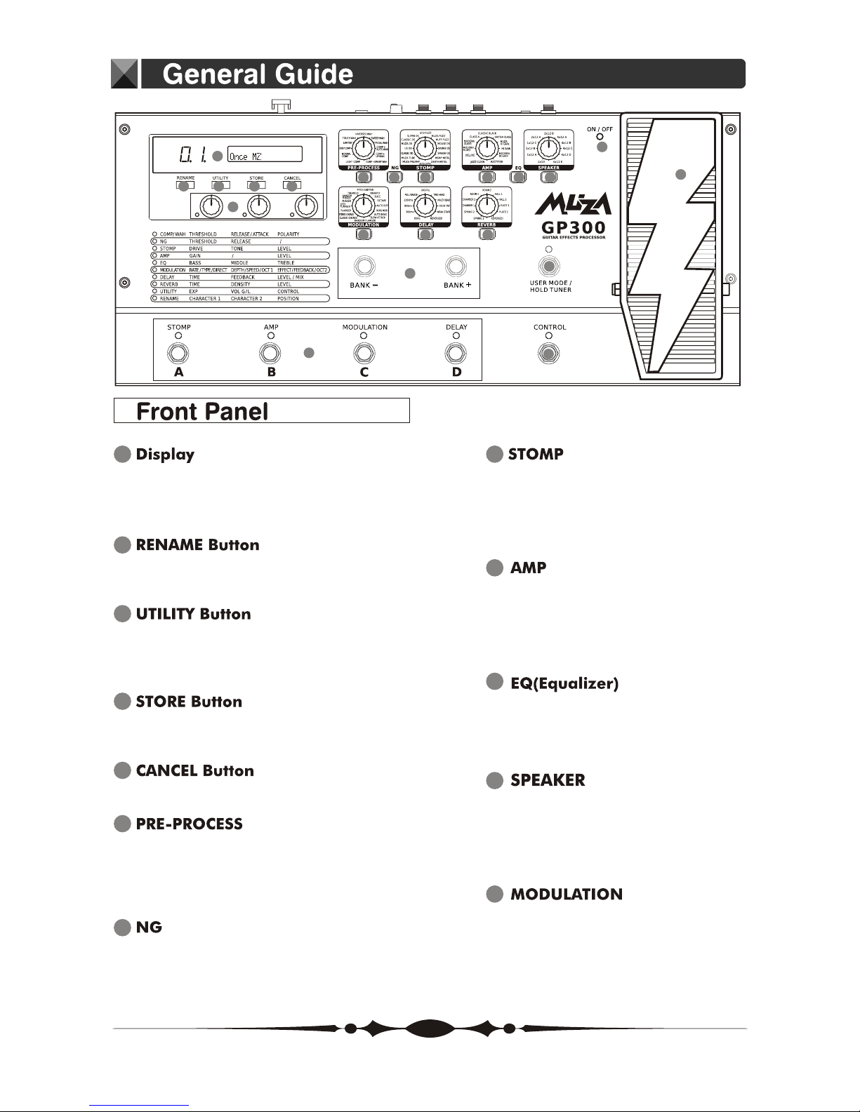
EQ(Equalizer) ON/OFF Button
Press to change the equalizer of a
tone.
9
AMP ON/OFF Button
Press to change settings.
Select the amp type.
AMP Knob
A variety of information about the unit
appears here.
The left display shows the bank number.
1
Use for changing the 60 user patches
name.
2
3
Select the PEDAL function, volume
control global or local and the CONTROL
effect.
4
Use to save the settings you have
created.
5
Use this to undo operations.
7
Press to change settings.
NG ON/OFF Button
6
Press to change the settings.
Select the pre-process type.
PRE-PROCESS ON/OFF Button
PRE-PROCESS Knob
8
STOMP ON/OFF Button
Press to change settings.
Select the stomp type.
STOMP Knob
1
2 3 4 5
6 87
10
9
11
20
21
12
13
14
15
17
19
16
18
12
Press to change settings.
Select the modulation type.
MODULATION ON/OFF Button
MODULATION Knob
11
SPEAKER ON/OFF Button
Press to change settings.
Select the speaker type.
SPEAKER Knob
5
1 2 3
4
5 6 7 8
General Guide
Value knobs 1-3
19
To adjust the parameters of the effects
or amp model.
Expression Pedal
20
Controls volume when the light is off
and the other functions of expression
when the light is on.
Expression Pedal LED
21
Lights when the effect being controlled
with the Expression Pedal is on, and
goes out when the effect is off.
BANK Switches
15
Switching bank numbers upwards or
downwards.
USER MODE/HOLD TUNER Switch
16
Press to enter user mode and the tuner
and bypass functions.
Number Switches
17
To select a desired patch.
CONTROL Switch
18
You can use value knob 3 to edit the
control pedal setting.
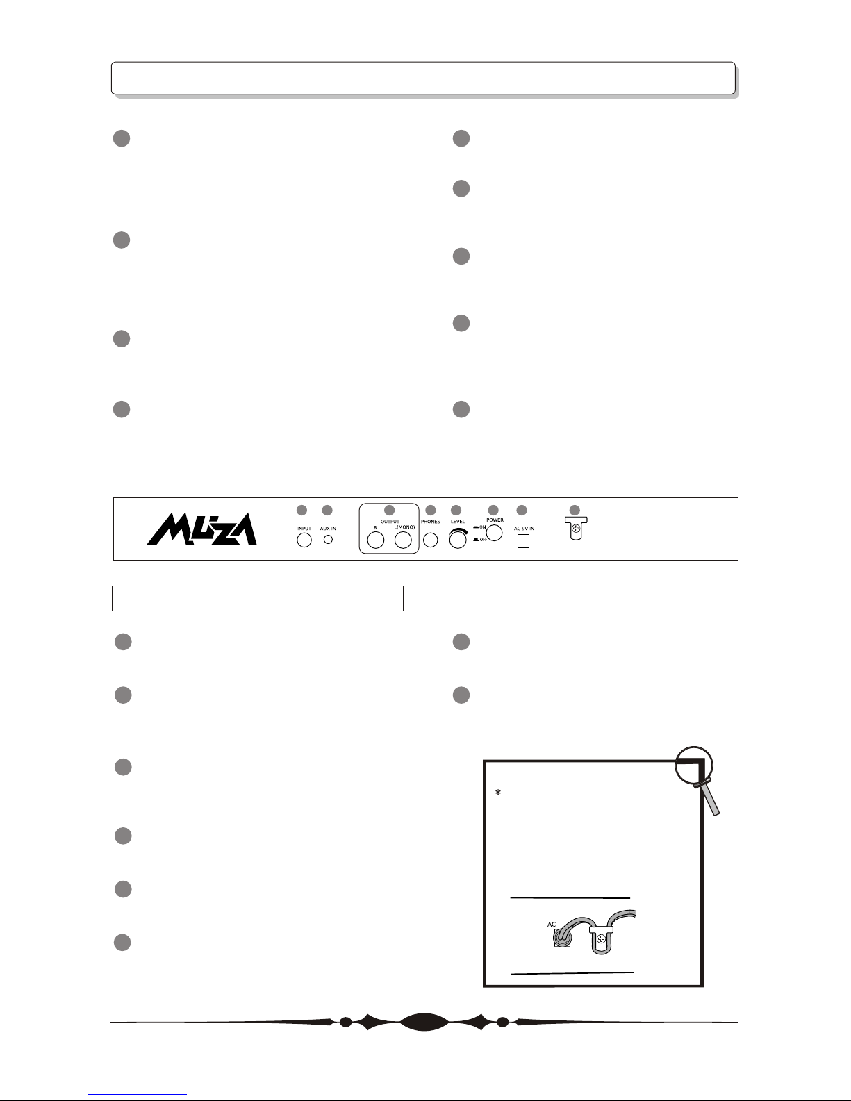
1
INPUT Jack
Connect your guitar to this jack.
2
AUX IN Jack
Connect an external effect processor or
other audio source to this jack.
3
OUTPUT R/L(MONO) Jack
Connect to an amp, mixer, mixer or
similar devices.
4
PHONE Jack
Connect your headphones to this jack.
5
LEVEL Knob
Adjust the volume level of the unit.
6
POWER Switch
Turn the power on and off .
7
AC IN Jack
Connect an AC adapter to this jack.
8
Cord Hook
Hook the AC adapter cord to prevent
the adapter for disconnection.
Rear Panel
6
13
DELAY
Press to change settings.
Select the delay type and time.
DELAY ON/OFF Button
DELAY Knob
14
REVERB
Press to change settings.
Select the reverb effect.
REVERB ON/OFF Button
REVERB Knob
Fasten the cord of the AC adapter
around the hook as shown in the
diagram before connecting it to
the AC IN jack. This will prevent
the plug from being disconnected
if the cord is accidentally pulled.
Operation
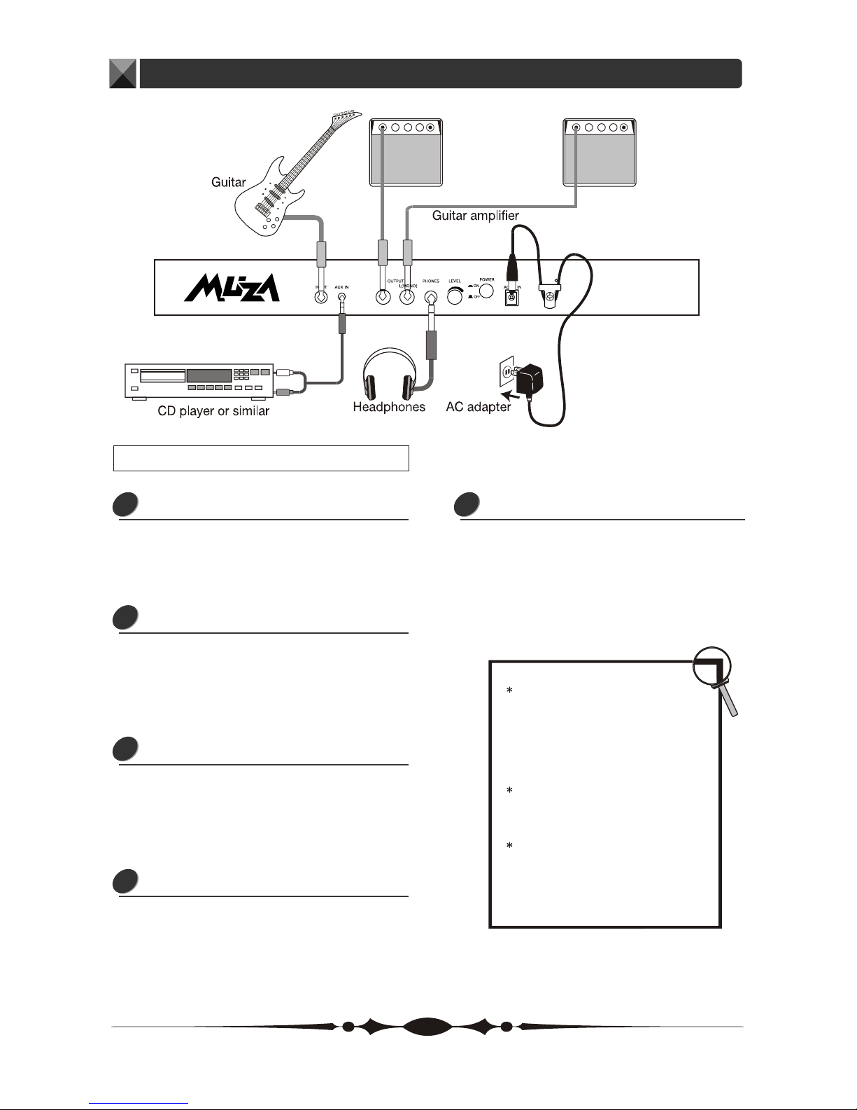
Connecting a Guitar
Plug an audio cord into the INPUT jack.
Then plug the other end of the cord
into LINE OUT of a guitar.
1
Connecting an Audio Source
Plug an audio cord into the AUX IN jack.
Then plug the other end of the cord
into the LINE OUT or the AUX OUT of
a CD or similar devices.
2
Connecting Guitar Amplifier
Plug two audio cords into the OUTPUT
jack, then plug the other end of the
cords into the AUX IN jack of the two
amplifiers.
3
Connecting Headphone
Plug a pair of headphone into the
PHONES jack to monitor the sound.
4
Connecting Power Adapter
To power the unit from the AC adapter,
insert the small plug of the adapter
cable into the AC IN jack. Then plug
the adapter into an outlet.
5
7
Connection
To prevent malfunction and/or
damaging the speakers or other
devices, always turn down the
volume, and turn the power of
all devices off before making any
connection.
When outputting in mono, connect
the cord to the OUTPUT L(MONO)
jack.
If you turn on the unit while the
amplifier is already powered up,
damages to the speaker may result.
Always turn the power of the amplifier
off before making any connection.
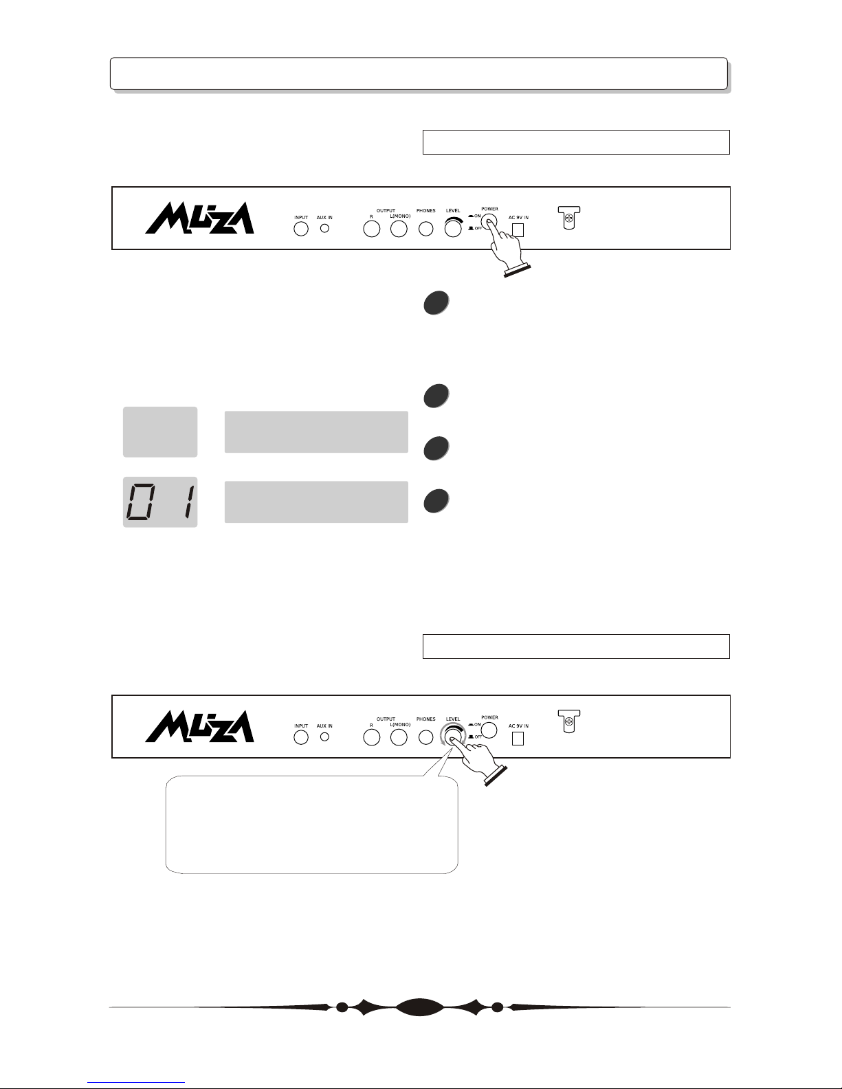
Operation
Power Supply
Volume Adjustment
Once the connections have been
completed, turn the power of the
various devices on in the order
sequence as below.
Press the POWER ON/OFF button to
turn on the unit.
After the power is on, the LCD will
proceed to the main operation menu.
The LCD displays current patch's
name and the LED displays the BANK
number. The LED lights turn on or off
according to each effect's status.
1
2
3
4
MUZA GP300
_
MUZA2006
8
Adjust the output volume of the unit
with the LEVEL knob on the rear panel.
 Loading...