

Muza FD800 Owner's Manual
Owner's Manual
DIGITAL MULTI
MODULATION EFFECTS
PEDAL
0
5
25
75
95
100
aw_FD800_Manual_G12_101118
20101118 12:49:57

INFORMATION FOR YOUR SAFETY!
PRECAUTIONS
PLEASE READ CAREFULLY BEFORE PROCEEDING.
Please keep this manual in a safe place for future reference.
2
Power Supply
Please connect the designated AC adaptor to an AC
outlet of the correct voltage.
Do not connect it to an AC outlet of voltage other than
that for which your instrument is intended.
Unplug the AC power adaptor when not using the
instrument, or during electrical storms.
Connections
Before connecting the instrument to other devices, turn
off the power to all units. This will help prevent
malfunction and / or damage to other devices.
Location
Do not expose the instrument to the following
conditions to avoid deformation, discoloration, or more
serious damage:
Direct sunlight
Extreme temperature or humidity
Excessive dusty or dirty location
Strong vibrations or shocks
Close to magnetic fields
Interference with other electrical devices
Radios and televisions placed nearby may experience
reception interference. Operate this unit at a suitable
distance from radios and televisions.
Cleaning
Clean only with a soft, dry cloth.
Do not use paint thinners, solvents, cleaning fluids, or
chemical-impregnated wiping cloths.
Handling
Do not apply excessive force to the switches or controls.
Do not let paper, metallic, or other objects into the
instrument. If this happens, unplug the AC adaptor from
the wall outlet. Then have the instrument inspected by
qualified service personnel.
Disconnect all cables before moving the instrument.
CAUTION
The normal function of the product may be disturbed
by Strong Electro Magnetic Interference. If so,
simply reset the product to resume normal operation
by following the owner’s manual. In case the function
could not resume, please use the product in other
location.
0
5
25
75
95
100
aw_FD800_Manual_G12_101118
20101118 12:49:57
Contents
3
Store and Recall Patches
Storing Your Favorite Tones 15
Recalling the Saved Memories 17
Advanced Use
FOOT SWITCH Control Mode 18
Additional Parameter Setting 19
Troubleshooting 22
Specifications 23
Appendices
Setting Samples 24
............................
.......................
........................
..........................
............................................
................................................
..............................................
Panel Description
Front Panel 4
Setup
Battery Replacement Diagram 6
Connection......................................................7
Effects Introduction
Effect Modes List 8
Effect Modes Introduction 9
01.Tremolo/Panner 9
02.Step Tremolo/Panner 9
03.Vibrator 10
04.Rotary 10
05.Chorus 10
06.Flanger 11
07.NFB Flanger 11
08.Tremolo Flanger 11
09.Phaser 12
10.Step Phaser 12
11.Step BP-Filter 12
12.Ring Modulation 13
13.Step Ring Modulation 13
14.2-Voice PitchShifter 13
15.Feedback PitchShifter 14
.......................................................
..........................
..............................................
.................................
...........................................
...................................
.......................................................
.........................................................
.......................................................
.......................................................
...............................................
.........................................
........................................................
...............................................
.............................................
.........................................
.................................
....................................
................................
0
5
25
75
95
100
aw_FD800_Manual_G12_101118
20101118 12:49:57
Panel Description
Front Panel
4
11
0
5
25
75
95
100
aw_FD800_Manual_G12_101118
20101118 12:49:59

Panel Description
5
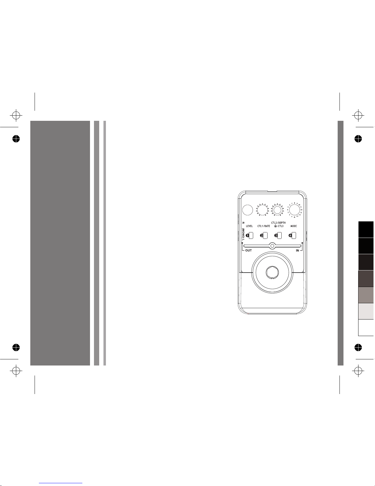
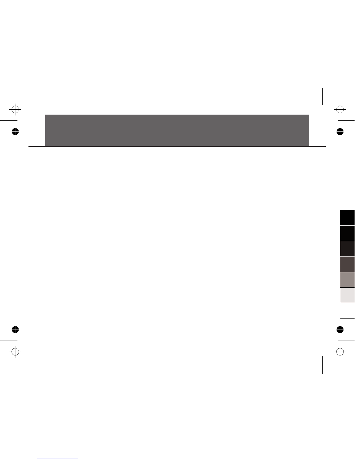
1.LEVEL Knob
Control the OUTPUT LEVEL or EFFECT
LEVEL or BALANCE of the selected effect.
2.CTL1/RATE Knob
Turn this knob to control RATE or 1st
parameter of the selected effects.
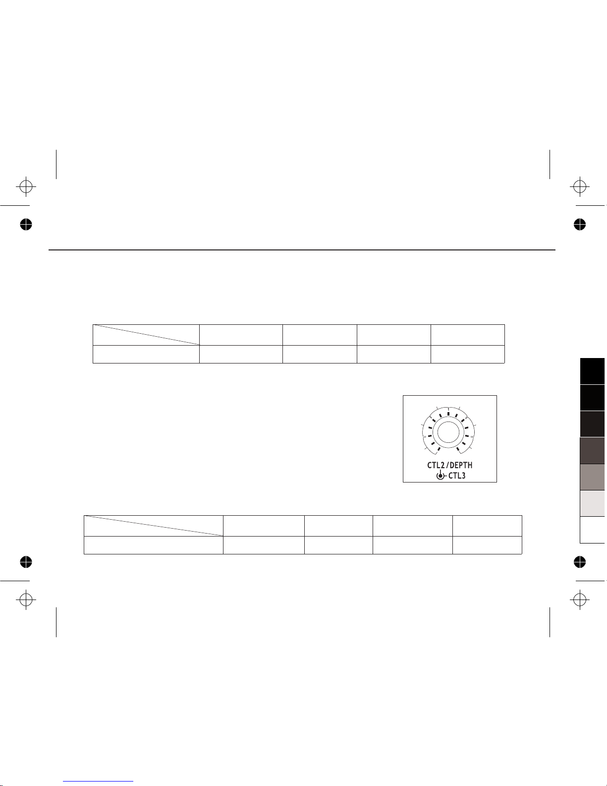
3.CTL2/DEPTH Knob
Turn this knob to control DEPTH or 2nd
parameter of the selected effects.
4.CTL3 Knob
Turn this knob to control 3rd parameter of the
selected effects.
5.MODE Knob
Select one modulation effect among the 15
effects, or to select the patch memory function.
6.PATCH MEMORY Buttons
Press any of the PATCH MEMORY buttons to
store your favorite tones to one of the four
patch memory buttons (When the “MODE”
knob on the M position is selected).
7.ON/OFF LED
Indicate the on/off status of the unit.
8.FOOT SWITCH
Press the switch to turn effects on and off or
for patch memory selection.
9.POWER Jack
Plug the 9V power adaptor into this jack.
10.INPUT Jack
Connect your guitar to this jack. Connect a
guitar cable to this jack for power supply
when using a battery.
11.OUTPUT Jack
OUT-L(MONO)
Connect this output jack to your guitar amplifier.
OUT-R
Connect this output jack to another amplifier.
Notice:
You can also send this 2 combinational output
jack's stereo signal to amplifier, mixer, audio
interface, or another effect processor.
0
5
25
75
95
100
aw_FD800_Manual_G12_101118
20101118 12:50:00
Setup
6
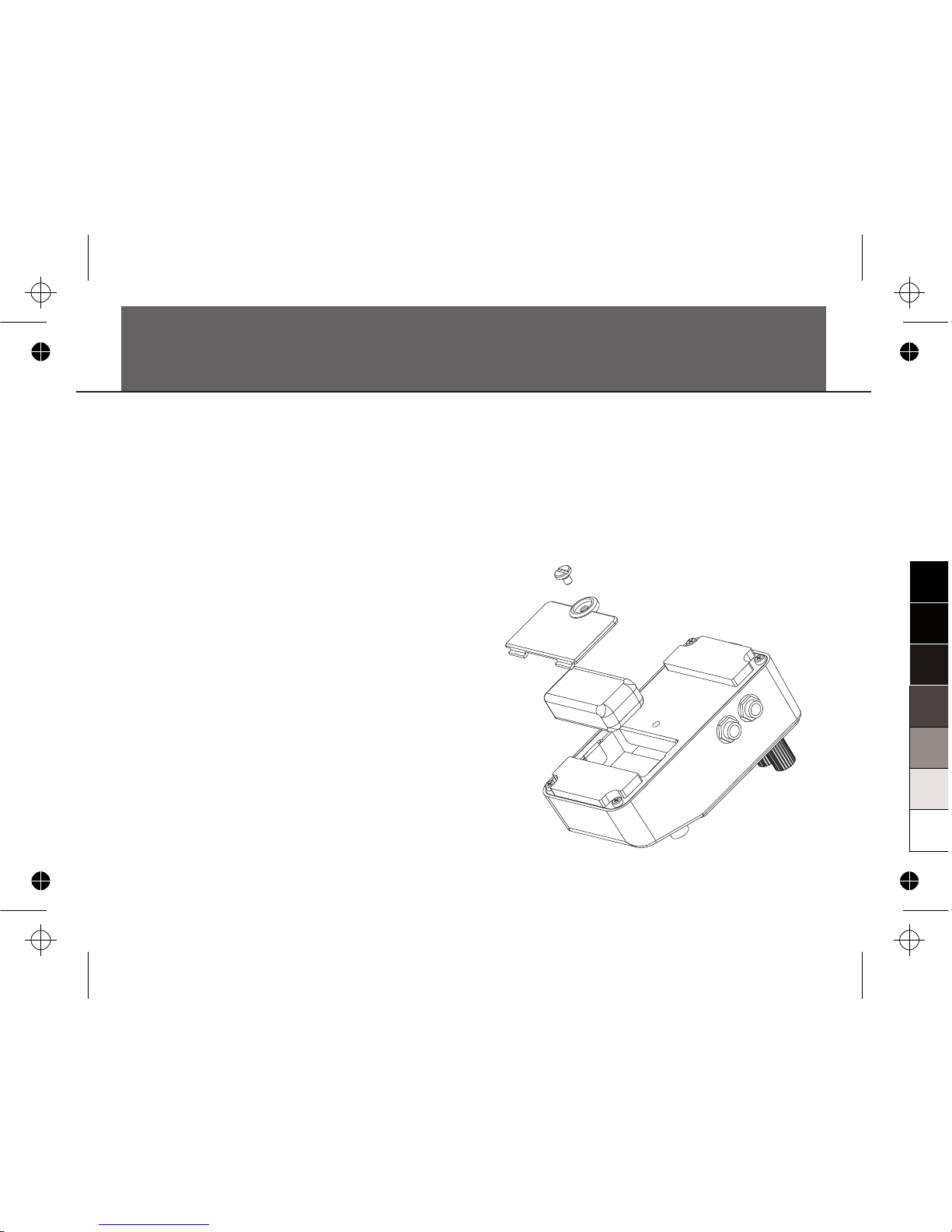
Battery Replacement Diagram
Warning:
1. A 9V battery must be installed
before you plug the mono audio cable into
the input jack.
2. While the power supply is low, the LED will
extinguish. Please replace the battery
accordingly.
3. Turn the guitar amplifier off before plugging
and unplugging cables, otherwise
tremendous noise might be produced and
the unit might be damaged as well.
(optional)
0
5
25
75
95
100
aw_FD800_Manual_G12_101118
20101118 12:50:00
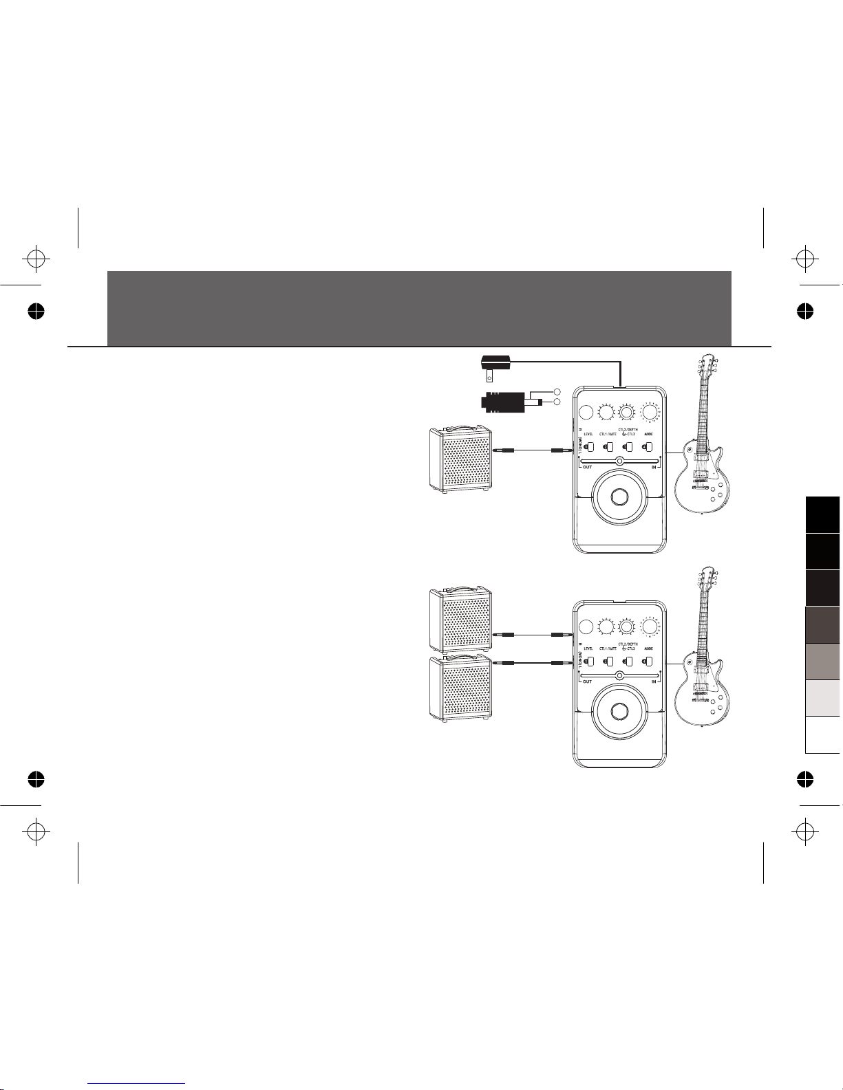
7
Connection
Connection
1. Connect the optional power supply to the
power jack or insert a 9V battery (optional)
into the battery compartment on the bottom.
2. Connect your guitar to input jack and an
amplifier to output jack of the Pedal.
3. The Pedal will automatically switch on after a
cable is plugged into its L-input jack when
using a battery.
Use only the appropriate adaptor with the
correct voltage and with a center NEGATIVE
polarity. Some adaptors are made with a
different polarity or voltage, which may
damage the unit if it has been falsely used in
connection.
AC Adapto r
OUT DC 9V
-
+
OUT L (MONO )
OUT L
OUT R
Amplifier II
Amplifier I
0
5
25
75
95
100
aw_FD800_Manual_G12_101118
20101118 12:50:00
Effects Introduction
8
This digital multi modulation effects pedal
contains 15 excellent modulation effects. It also
includes the storage function, allows you to
store and recall up to 4 patch memories.
Effects List
No.
1
2
3
4
5
6
7
8
9
10
11
12
13
14
15
EFFECT MODES
TREMOLO/PANNER
STEP TREMOLO/PANNER
VIBRATOR
ROTARY
CHORUS
FLANGER
NFB FLANGER
TREMOLO FLANGER
PHASER
STEP PHASER
STEP BP-FILTER
RING MODULATION
STEP RING MODULATION
2-VOICE PITCH SHIFTER
FEEDBACK PITCH SHIFTER
0
5
25
75
95
100
aw_FD800_Manual_G12_101118
20101118 12:50:00
01. Tremolo/Panner
This effect produces TREMOLO effect when using a mono output cable, and produces PANNER
effect when using a stereo output cable.
Turn the CTL3 knob to change modulation WAVE from TRIANGLE WAVE→SINE WAVE→
SQUARE WAVE gradually.
9
Effects Introduction
KNOBS
EFFECT
TREMOLO/PANNER
LEVEL CTL1/RATE CTL3CTL2/DEPTH
OUTPUT LEVEL RATE DEPTH WAVE
KNOBS
EFFECT
STEP TREMOLO/PANNER
LEVEL CTL1/RATE CTL3CTL2/DEPTH
EFFECT LEVEL STEP RATE WIDTH STEP BEAT
02. Step Tremolo/Panner
This effect produces TREMOLO effect with step function when
using mono output cable, and produces PANNER effect with step
function when using stereo output cable.
Turn the CTL2 knob to set the range of sound width.
Turn the CTL3 knob to set the beat of a bar, there are 6 kinds of
beat could be chosen: 3, 4, 5, 6, 7, 8, could be consider as 3/4,
4/4, 5/4, 6/4, 7/4, 8/4, by using step tremolo, you can hear 3-8
notes which appeared from left to right each period (“stereo out”).
The picture will show you how to choose the step beat:
3
4
5 6
7
8
0
5
25
75
95
100
aw_FD800_Manual_G12_101118
20101118 12:50:00
Effects Introduction
03. Vibrator
It provides VIBRATO effect.
10
KNOBS
EFFECT
VIBRATO
LEVEL CTL1/RATE CTL3CTL2/DEPTH
OUTPUT LEVEL RATE DEPTH TONE
04. Rotary
It simulates a rotary speaker.
Turn the CTL3 knob to adjust the level of modulation panner.
KNOBS
EFFECT
ROTARY
LEVEL CTL1/RATE CTL3CTL2/DEPTH
OUTPUT LEVEL RATE DEPTH MOD. PAN
05. Chorus
It provides CHORUS effect with stereo output.
When using ADDITIONAL PARAMETER SETTING function, turn LEVEL knob to adjust the PRE DELAY.
KNOBS
EFFECT
STEREO CHORUS
LEVEL CTL1/RATE CTL3CTL2/DEPTH
EFFECT LEVEL
(PRE-DELAY)
RATE DEPTH EFFECT TONE
0
5
25
75
95
100
aw_FD800_Manual_G12_101118
20101118 12:50:00
 Loading...