

Page 1
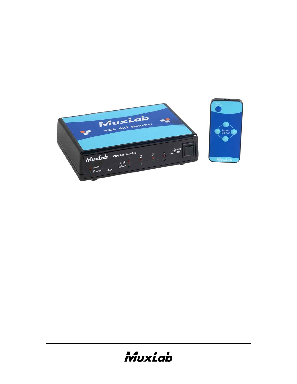
VGA 4x1 Switcher
500160 [110V], 500161 [220-240V]
Installation Guide
P/N: 94-000649-A SE-000649-A
Page 2

© MuxLab Inc. VGA 4x1 Switcher Installation Guide
P
Copyright Notice:
Copyright © 2009 MuxLab Inc. All rights reserved.
Printed in Canada. No part of this publication may be reproduced,
stored in a retrieval system, or transmitted in any form or by any
means, electronic, mechanical, photocopying, recording or
otherwise without prior written permission of the author.
Trademarks:
MuxLab is a registered trademark of MuxLab Inc.
age 2
Page 3

© MuxLab Inc. VGA 4x1 Switcher Installation Guide
P
Table of Contents
1. Overview .........................................................................4
1.1. Description........................................................4
1.2. Features 5
2. Technical Specifications ................................................6
3. Installation Procedure ...................................................7
3.1. Parts List ...........................................................7
3.2. Product Overview .............................................8
3.3. Pre-Installation Checklist .................................9
3.4. Installation Procedure .....................................11
3.5. Cascadability ..................................................14
3.6. Port Control Operation ...................................15
3.7. Driver Setup....................................................16
3.8. MuxLab Control Center Software ..................19
4. Troubleshooting ...........................................................24
5. Appendix.......................................................................26
A. ASCII Command Set ......................................26
B. Infrared Remote Control Codes......................30
6. Product Warranty Policy ............................................31
age 3
Page 4

© MuxLab Inc. VGA 4x1 Switcher Installation Guide
P
1.
Overview
1.1. Description
The VGA 4x1 Switcher allows the user to select any one
of up to four (4) VGA (RGBHV) sources for one (1)
display via Cat 5e/6 cables for more cost-efficient
cabling. The Switcher works in conjunction with the
following MuxLab products:
500140: Active VGA Balun II Kit (Tx & Rx)
500141: Active VGA Balun II, Tx, no PSU
500142: Active VGA Balun II, Rx, no PSU
500144: Power Supply for 500141 and 500142
500150/500151: VGA 1x4 Distribution Hub
At least one (1) Kit is required to support one (1) source.
The Kit includes one (1) Transmitter and one (1)
Receiver. Up to three (3) additional Transmitters may be
added to support up to three (3) additional sources. The
500144 may be needed for each the 500141 and the
500142 for extended distance.
age 4
Page 5

© MuxLab Inc. VGA 4x1 Switcher Installation Guide
P
1.2. Features
Plug-and-Play: DDC1/DDC2 compliant
•
Remote power pass-through
•
Automatic port selection
•
Manual port selection via infrared remote control,
•
pushbutton, USB and RS232
Up to 600 ft (183 m) via Cat 5e/6 @ 1920 x 1440
•
Up to 600 ft (183 m) via Cat 5e/6 @ 1080p
•
Cascadable up to four (4) levels
•
Modular RJ45 on input and output
•
Ground loop isolation on every port
•
Works with Active VGA Balun II products (500140,
•
500141, 500142, 500144) and VGA 1x4 Distribution
Hub (500150, 500151)
Supports VGA and RGB/YPbPr
•
age 5
Page 6
© MuxLab Inc. VGA 4x1 Switcher Installation Guide
P
2.
Technical Specifications
Environment
Devices
Transmission
Bandwidth
Impedance: Video
Connectors
DDC Control
Remote Power
Max Distance:
Remote Power
Max Distance:
VGA Source to Display
Switcher may be placed
anywhere in between
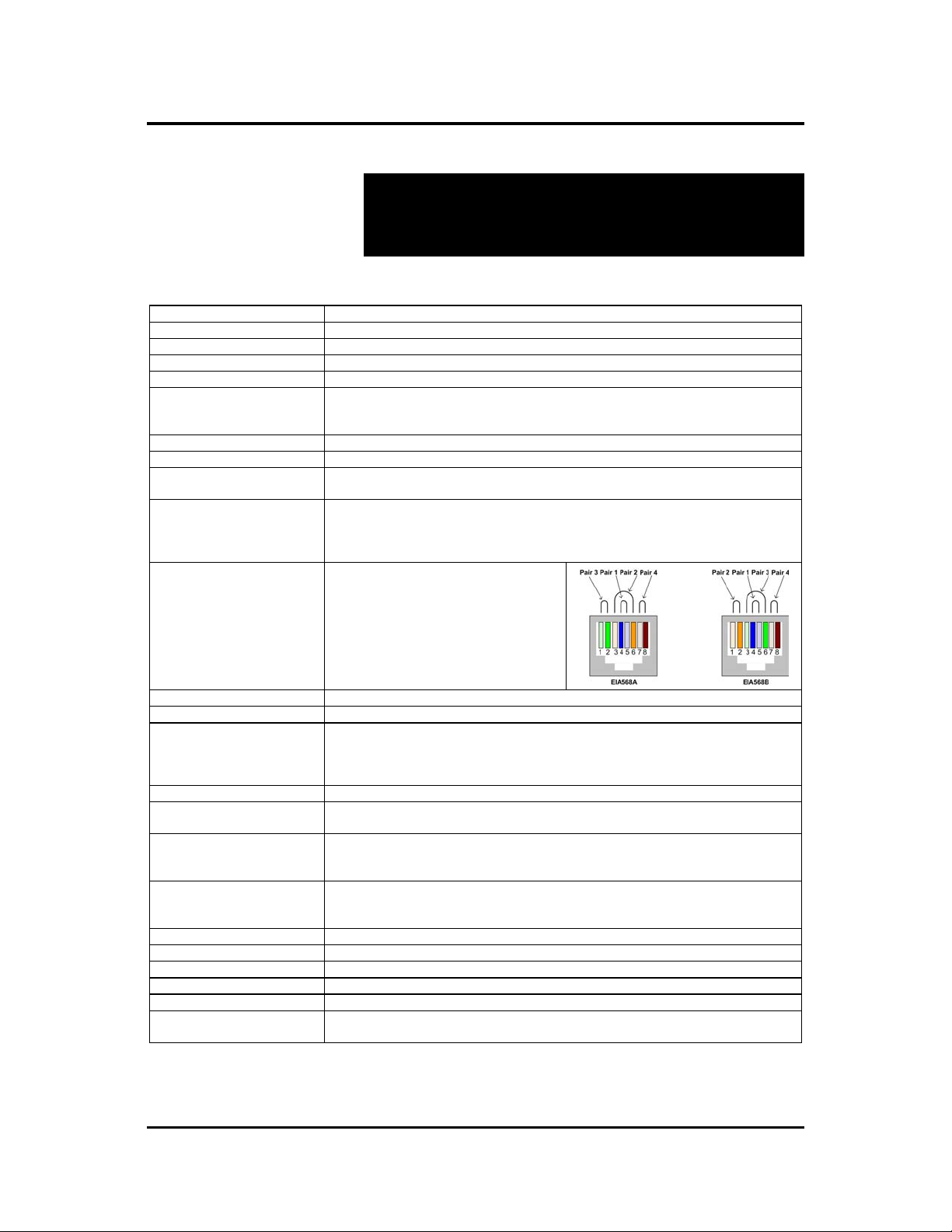
RJ45 Pin Configuration
Reverse Polarity Sensitive
Use EIA/TIA 568A or 568B
straight-through wiring
Gain Adjustment
Software
LED Indicators
Cable
Ground Loop Isolation
Power Supply
Temperature
Enclosure
Dimensions
Weight
Regulatory
Warranty
Order Information
VGA. VESA VP&D 1.0, VIP ver 2.0 and DDC1
PCs, laptops, CRT monitors, LCD monitors, plasma screens, DLP projectors.
Transparent to the user
Up to 280 MHz (1920 x 1440 resolution), 1080p
Coax: 75 ohms UTP: 100 ohms
VGA Input (Cat 5e/6): Four (4) RJ45 shielded
VGA Output (Cat 5e/6): One (1) RJ45 shielded
USB and RS232 connectors for switcher control
Transmits DDC control signals on pins 4&5 for plug-and-play operation
Transmits remote DC power on pins 4&5
Tx Balun to Switcher: 150 ft (46 m)
Switcher to Rx Balun: 150 ft (46 m)
640 x 480 (VGA): 1,000 ft (305 m)
800 x 600 (SVGA): 1,000 ft (305 m)
1024 x 768 (XGA): 1,000 ft (305 m)
1280 x 1024 (SXGA): 850 ft (260 m)
Red................................ Pin 7 (R) Pin 8 (T)
Green............................. Pin 3 (R) Pin 6 (T)
Blue............................... Pin 1 (R) Pin 2 (T)
DDC/Remote Power ..... Pin 4 (R) Pin 5 (T)
Gain compensation rotary switch and a potentiometer for equalization
Includes USB flash drive containing port control software
Auto: One (1) amber LED
Power: One (1) green LED
Link: Four (4) amber LEDs
Select: Four (4) green LEDs
Cat 5e/6 unshielded twisted pair (or better)
Ground loop isolation on every port.
–2VDC to +3VDC between PC and display ground
110-240V/12VDC/3.35A.
Detachable AC power cords included
12VDC power jacks
Operating: 0ºC to 40ºC
Storage: -10ºC to 70ºC
Humidity: Up to 95% non-condensing
Black. ABS fire retardant plastic
6.00” x 4.25” x 1.50” (15.3 cm x 10.8 cm x 3.8 cm)
2.4 lbs (1.1 kg)
FCC Class A, CE, RoHS
Two (2) years
500160: VGA 4x1 Switcher, 110V
500161: VGA 4x1 Switcher, 220-240V
1366 x 768 (WXGA): 850 ft (260 m)
1680 x 1050 (WSXGA): 850 ft (260 m)
1600 x 1200 (UXGA): 800 ft (245 m)
1920 x 1200 (WUXGA): 600 ft (180 m)
age 6
Page 7

© MuxLab Inc. VGA 4x1 Switcher Installation Guide
P
3.
Installation Procedure
3.1. Parts List
The VGA 4x1 Switcher (500160, 500161) comes with
the following parts:
Base Unit
•
One (1) External Power Supply
•
One (1) AC Power Cord (North American or
•
Continental Europe)
One (1) Infrared Remote Control
•
One (1) Battery for Infrared Remote Control
•
One (1) USB Type A-Type B Cable
•
One (1) USB flash drive with Port Control Software
•
Installation Guide
•
Please verify that all pieces are present before
proceeding.
VGA, RS232 and Cat 5e/6 cables are not included. The
driver setup installation file (SC-000020) and the
MuxLab Control Center software (SC-000015) are
located on the USB flash drive and can also be
downloaded at http://www.muxlab.com
age 7
.
Page 8
© MuxLab Inc. VGA 4x1 Switcher Installation Guide
P
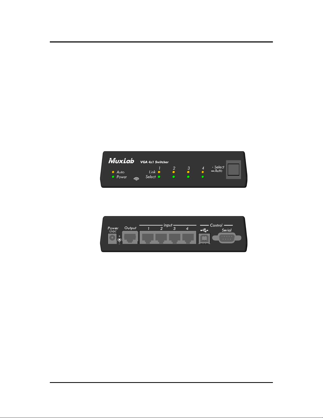
3.2. Product Overview
The external connections and diagnostic indicators of
the VGA 4x1 Switcher are detailed in the following
diagrams. Please familiarize yourself with them before
installing the components.
Figure 1: Front End Panel
Figure 2: Rear End Panel
age 8
Page 9

© MuxLab Inc. VGA 4x1 Switcher Installation Guide
P
3.3. Pre-Installation Checklist
The VGA 4x1 Switcher works in conjunction with the
Active VGA Balun II Kit (500140), the Active VGA
Balun II Transmitter (500141), the Active VGA Balun II
Receiver (500142), and Balun Power Supply (500144).
1. Verify that you have all the components necessary to
install the complete system and determine the final
location for each piece of equipment.
2. One (1) Kit (500140) is needed to support the first
source. Each Kit includes one (1) Transmitter
(500141), one (1) Receiver (500142), and two (2)
Power Supplies (500144).
3. One (1) additional Transmitter (500141) is required
for each additional source.
4. Consult the Technical Specifications to determine
whether the Switcher and Active VGA Balun II
components are within MuxLab distance limitations
for Remote Power. If so, only the Switcher needs to
be powered.
5. If extended distance is required beyond the limits of
Remote Power, verify that each Active VGA Balun
II component is powered by its own power supply.
Additional 12VDC/0.5A Balun Power Supplies
(500144) may be ordered from your MuxLab
distributor.
age 9
Page 10

© MuxLab Inc. VGA 4x1 Switcher Installation Guide
P
6. Verify that the screen resolution and cable lengths
are within MuxLab specifications (see Technical
Specifications).
age 10
Page 11

© MuxLab Inc. VGA 4x1 Switcher Installation Guide
P
3.4. Installation Procedure
In order to install the VGA 4x1 Switcher, please follow
the steps below:
1. Install the VGA 4x1 Switcher in its final location.
2. Connect an Active VGA Balun II Transmitter to
each VGA source. If there are any local monitors,
connect them to the Local Monitor Output of the
associated Active VGA Balun II Transmitter via a
VGA cable (not included).
3. If the distance exceeds the MuxLab specification for
remote power, connect a Power Supply (500144) to
the Active VGA Balun II Transmitter. The green
power LED should be ON.
4. Connect a length of Cat 5e/6 (or better) UTP cable
between the each Active VGA Balun II Transmitter
and the VGA 4x1 Switcher.
5. Connect an Active VGA Balun II Receiver to the
display.
6. If the distance exceeds the MuxLab specification for
remote power, connect a Power Supply (included
with the Active VGA Balun II Kit) to the Active
VGA Balun II Receiver. The green power LED
should be ON.
age 11
Page 12

© MuxLab Inc. VGA 4x1 Switcher Installation Guide
P
7. Connect a Cat 5e/6 (or better) UTP cable between
the VGA 4x1 Switcher and the Active VGA Balun II
Receiver.
8. The Active VGA Balun II features a gain
compensation rotary switch and a potentiometer for
equalization. For more information, please refer to
the Active VGA Balun II Installation Guide.
9. The factory default setting of the switcher upon
power-up is automatic port selection mode. To select
a port manually, press the push button until the
Select
LED of the desired port is illuminated. To
switch back to automatic mode, hold the pushbutton
down for 3 seconds. The amber
Auto
LED will
again be ON.
10. Assemble the infrared remote control as shown in
Figure 3. To manually select the desired port with
the infrared remote control, press the numbered
buttons. To switch back to automatic mode, press the
Auto Mode
button.
Figure 3: Infrared Remote Control Assembly
age 12
Page 13

© MuxLab Inc. VGA 4x1 Switcher Installation Guide
P
11. In order to control the Switcher via USB, connect
the USB cable between the Switcher and the PC.
Similarly, to control the Switcher via RS232,
connect an RS232 cable (not included) between the
Switcher and the PC. Refer to Section 3.6 for the
RS232 cable configuration. Note: Connect only a
USB cable or an RS232 cable (not both) between the
Switcher and the PC.
12. Figure 4 shows a typical configuration.
Figure 4: Typical Configuration
age 13
Page 14

© MuxLab Inc. VGA 4x1 Switcher Installation Guide
P
3.5. Cascadability
In order to distribute from one (1) of up to four (4) VGA
sources to more than one (1) display, the VGA 4x1
Switcher may be cascaded with up to three (3) levels of
the VGA 1x4 Distribution Hub. In other words, any one
of up to four (4) VGA sources may be selected to feed
up to sixty-four (64) displays. For illustration purposes,
Figure 5 shows one (1) level of cascading for up to four
(4) displays.
Figure 5: Cascading Illustration
age 14
Page 15

© MuxLab Inc. VGA 4x1 Switcher Installation Guide
P
3.6. Port Control Operation
The VGA 4x1 Switcher features built-in firmware that
allows commands from an ASCII terminal to be sent
directly to the device via either a USB or RS232
connection (not both simultaneously). If connecting with
an RS232 cable, ensure that the cable has the straightthrough configuration shown in Figure 6.
2
3
5
DB9
Male
Figure 6: RS232 Cable Configuration
2
3
5
DB9
Female
Port Control is performed with either the MuxLab
Control Center software, described in Section 3.7, or
with a terminal emulator such as the one available under
Windows with the ASCII Command Set described in
Appendix A. Please note that USB to RS232 converter
cables are not supported.
age 15
Page 16

© MuxLab Inc. VGA 4x1 Switcher Installation Guide
P
3.7. Driver Setup
When interfacing a MuxLab device with Windows 2000
(or more recent) operating system, a driver setup file
will be required.
To install the MuxLab Control Center software, insert
the USB flash drive into the PC. Plug the USB cable
between the device and the PC, and power up the
device. The
(Figure 7). Select
Found New Hardware
Figure 7: Found New Hardware Wizard
wizard will open
Locate and install driver software
.
age 16
Page 17

© MuxLab Inc. VGA 4x1 Switcher Installation Guide
P
A new dialog box will open (Figure 8). Select
my computer for driver software
Figure 8: Found New Hardware Dialog Box
.
Another dialog box will open (Figure 9). Click
Browse
Browse
and locate the USB flash drive. Once found, click
Figure 9: Browsing for Unknown Device
Next
.
age 17
Page 18

© MuxLab Inc. VGA 4x1 Switcher Installation Guide
P
A security window will now appear, indicating that the
driver software is unsigned (Figure 10). Select
this driver software anyway
Figure 10: Windows Security
.
Install
A final window will appear indicating that the software
for the driver has been successfully installed (Figure
11). Click
Close
. You are now ready to launch the
MuxLab Control Center software.
Figure 11: Successful Installation Dialog Box
age 18
Page 19

© MuxLab Inc. VGA 4x1 Switcher Installation Guide
P
3.8. MuxLab Control Center Software
MuxLab provides the user with software for operating
the VGA 4x1 Switcher via a PC. Each Switcher has 4
input ports and 1 output port, and the MuxLab Control
Center software enables the user to select which input
port to feed to the output port.
To install the MuxLab Control Center software, insert
the USB flash drive into the PC, open the folder, and
double click the SC-000015 file.
When running the MuxLab Control Center software for
the first time, the main window will appear (Figure 12).
Figure 12: MuxLab Control Center Main Window
On the left is the
Port Selection
may be a Switcher (as in this case), or any other
software-controllable MuxLab product. Depending on
the type of device selected, the tabs on the right will
change. For a Switcher, the
with the Switcher’s input ports, and the way in which
Devices
and
tree, and on the right are the
Configure Device
Port Selection
age 19
tabs. A device
tab deals
Page 20

© MuxLab Inc. VGA 4x1 Switcher Installation Guide
P
they are selected to be fed to the output port. The
Configure Device
tab deals with naming a Switcher,
along with each of its input ports, as well as the COM
port on the PC to which the Switcher is connected.
Once all hardware has been connected, the user must
perform the following three steps:
1. Load a device
2. Configure a device
3. Choose a port selection method for a device
1. Loading a Device
Loading a device consists of detecting a Switcher (or
other software-controllable MuxLab product) connected
to the PC. Loading can be done either automatically or
manually. Once a device has been successfully loaded, it
will be displayed in the
To load devices automatically, select
Devices
tree.
Devices>Load All
Connected Devices…
Figure 13: Loading All Connected Devices
(Figure 13).
age 20
Page 21

© MuxLab Inc. VGA 4x1 Switcher Installation Guide
P
Automatically loading a device detects the Switcher
connected to a PC, as well as the COM port on the PC to
which it is connected.
To load devices manually, select
Device…
This loads devices one at a time, and does not
Devices>Add
automatically detect the COM port on the PC to which
the device is connected. This COM port assignment
must be completed in the
Configure Device
tab. Until
this assignment is completed by the user, the loaded
device will appear in brackets as “offline” in the
Devices
tree.
2. Configuring a Device
Configuring a device consists of three operations:
(i) Assigning a PC COM port to the device
(ii) Naming the device
(iii) Naming the four input ports on the device
To configure a device, select the device in the Devices
tree and click the
Configure Device
tab (Figure 14).
Figure 14: The Configure Device Tab
age 21
Page 22

© MuxLab Inc. VGA 4x1 Switcher Installation Guide
P
If a device has been loaded manually, a COM port on
the PC must first be selected by clicking the down arrow
next to
port and finalize this choice by clicking on the
Changes
Connect Using
. The user can then select a COM
Apply
button. Once this is done, other fields will no
longer be grayed out, and the user can proceed to name
(or rename) a device and its four input ports.
3. Choosing a Port Selection Method
Once a device has been loaded and configured, it can be
controlled by the user via the
Port Selection
tab. This
consists of selecting which of a device’s four input ports,
each assigned a unique number from 1 to 4, will be fed
to the device’s output port. Port selection can be done
either automatically or manually:
Automatic Port Selection chooses the lowest numbered
connected
input port on a device to feed to its output
port. For example, if all 4 input ports on a device are
connected to sources, Automatic Port Selection will feed
input port 1 on the device to its output. If input port 1
were then to be disconnected from its source, Automatic
Port Selection would feed input port 2 on the device to
its output. If only input ports 3 and 4 are connected to
sources, Automatic Port Selection would feed input port
3 on the device to its output.
Manual Port Selection leaves the choice of which input
port on a device to feed to its output entirely up to the
user. In fact the user can choose to feed an input port
with no signal
to the output port of a device. Please note
that when no signal is detected at an input port, the
expression
(No Signal Detected)
will be appended to
that port’s name (Figure 15).
age 22
Page 23

© MuxLab Inc. VGA 4x1 Switcher Installation Guide
P
Figure 15: The Port Selection Tab
age 23
Page 24

© MuxLab Inc. VGA 4x1 Switcher Installation Guide
P
4.
Troubleshooting
The following table describes some of the problem symptoms, the
probable causes and possible solutions. If the information below
does not solve the problem, the technical support contact
information can be found at the end of this section.
Problem LEDs Probable Cause Possible Solution
No Image Power: OFF No power • Check power connections
No Image Power: ON
No Image Power: ON
No Image Power: ON
Smearing Power: ON Cable length exceeded • Reduce cable length
Ghosting Power: ON Impedance mismatch • Check cabling
Wrong colors Power: ON Swapped pairs • Check wiring
Loss of detail Power: ON Cable length exceeded • Reduce cable length
Image shakes Power: ON Too much gain • Adjust gain and equalization on Active
Unable to open COM
port
Unable to open COM
port
When typing ASCII
commands, nothing
appears
When typing ASCII
commands, weird
characters appear
Auto: ON/OFF
Associated Sync: OFF
Associated Select: OFF
Auto: OFF
Associated Sync: ON
Associated Select: OFF
Auto: OFF
Associated Sync: ON
Associated Select: OFF
Auto: ON
Associated Sync: ON
Associated Select: ON
Power: OFF No power • Check power connections
Power: ON Wiring • Check continuity
Power: ON Wrong COM port setting
Power: ON Wrong COM port setting • Check that the terminal emulation program
Wiring • Check continuity
Wrong port selected • Select port manually No Image Power: ON
Wiring • Check continuity
Wrong port selected • Select port manually
Wiring • Check continuity
Local echo is off
• Check correct wiring
• Check cabling
• Check correct wiring
• Check cabling
• Unplug and replug all lower numbered ports
• Check correct wiring
• Check cabling
• Adjust contrast and brightness
• Try different VGA card or display
• Adjust contrast and brightness
VGA Balun II Receiver
• Check correct wiring
• Check cabling
• Check that the terminal emulation program
parameters match those listed in section 3.6
of this document
• Enable local echo in terminal emulation
software
parameters match those listed in section 3.6
of this document
age 24
Page 25

© MuxLab Inc. VGA 4x1 Switcher Installation Guide
P
When contacting your nearest MuxLab dealer or MuxLab
Technical Support (+1 514-905-0588), please have the following
information ready:
Unit model number.
•
Cabling layout. Include model of source equipment and
•
display used, cable length and type.
Description of problem.
•
List of tests performed.
•
age 25
Page 26

© MuxLab Inc. VGA 4x1 Switcher Installation Guide
P
5.
Appendix
A. ASCII Command Set
Ensure that the terminal emulation program parameters
are set to the following:
BAUD Rate: 9600
Data bits: 8
Stop bits: 1
Parity: None
Flow control: None
It should be noted that commands are case sensitive and
arguments must be separated by a single space.
Characters that are not supported will be rejected by the
response:
ILLEGAL CHARACTER
. Commands must
be entered in the following way and ended with a
carriage return:
version
Description: Returns firmware version
Example: version
Arguments: [none]
Response: Version X.X.X
Example: Version 1.0.0
age 26
Page 27

© MuxLab Inc. VGA 4x1 Switcher Installation Guide
P
get {port number}
Description: Returns the port or device name
Example: get 2
Arguments: port number
Number of port in context
(1, 2, 3, 4 or 0 for the device name)
Response:
X Port number (1, 2, 3, or 4)
YY..Y Name (up to 20 characters long)
Example: PORT2: Office1
get state
Description: Returns current state of device
Example: get state
Arguments: [none]
PORTX: YY..Y or DEVICE: YY..Y
Response: STATE X PORT Y LINKS Z,Z..Z
Y Port currently selected (1, 2, 3, 4 or
0 when no port is selected)
Z,Z..Z Port(s) detecting a link (1, 2, 3, or 4)
Example: STATE M PORT 2 LINKS 1,4
X M for manual, A for automatic
age 27
Page 28

© MuxLab Inc. VGA 4x1 Switcher Installation Guide
P
get
Description: Returns complete device configuration
Example: get
Arguments: [none]
Response: Version V.V.V
DEVICE: WW..W
PORT1: WW..W
PORT2: WW..W
PORT3: WW..W
PORT4: WW..W
STATE X PORT Y LINKS Z,Z..Z
WW..W Name (up to 20 characters long)
Y Port currently selected (1, 2, 3, 4 or
0 when no port is selected)
Z,Z..Z Port(s) detecting a link (1, 2, 3, or 4)
X M for manual, A for automatic
Example: Version 1.0.0
DEVICE: R&D SWITCHER
PORT1: JOHN’S PC
PORT2: MARK’S PC
PORT3: LAB PC
PORT4: PORT4
STATE M PORT 2 LINKS 1,4
age 28
Page 29

© MuxLab Inc. VGA 4x1 Switcher Installation Guide
P
set {port number} {name}
Description: Provides a port or the device with a name
Example: set 2 Office1
Arguments: port number
Number of port in context
(1, 2, 3, 4 or 0 to name the device)
name
The name (up to 20 characters long)
Response: PORTX: YY..Y or DEVICE: YY..Y
X Port number (1, 2, 3, or 4)
YY..Y Name (up to 20 characters long)
Example: PORT2: Office1
select {port number}
Description: Selects the appropriate port
Example: select 1
Arguments: port number
The port number to be selected
(1, 2, 3, 4, or a for automatic port selection)
Response:
AUTOMATIC MODE SELECTED
X Port currently selected (1, 2, 3, or 4)
Example: PORT 1 SELECTED
PORT X SELECTED
or
age 29
Page 30

© MuxLab Inc. VGA 4x1 Switcher Installation Guide
P
B. Infrared Remote Control Codes
Code (hex) Identification
00 Auto Mode
0D 1
12 2
15 3
10 4
age 30
Page 31

© MuxLab Inc. VGA 4x1 Switcher Installation Guide
P
6.
Product Warranty Policy
Items Under Warranty - Company Policy
MuxLab guarantees its products to be free of defects in manufacturing and workmanship for the
warranty period from the date of purchase. If this product fails to give satisfactory performance
during this warranty period, MuxLab will either repair or replace this product at no additional
charge, except as set forth below. Repair and replacement parts will be furnished on an exchange
basis and will be either reconditioned or new. All replaced parts and products become the property of
MuxLab. This limited warranty does not include repair services for damage to the product resulting
from accident, disaster, misuse, abuse, or unauthorized modifications or normal decay of battery
driven devices. Batteries, if included with the product, are not covered under this warranty.
Limited warranty service can be obtained by delivering the product during the warranty period to the
authorized MuxLab dealer from whom you purchased the product, or by sending it to MuxLab.
MuxLab will not accept any such product for repair without a Return Material Authorization number
(RMA#) issued by its Customer Service Department and a proof of purchase date. If this product is
delivered to MuxLab by mail, you agree to assume risk of loss or damage in transit, to prepay
shipping charges to the warranty service location, and to use the original shipping container or
equivalent.
THE ABOVE LIMITED WARRANTY IS THE ONLY WARRANTY COVERING YOUR
MUXLAB PRODUCT. THERE ARE NO OTHER WARRANTIES, EXPRESSED OR IMPLIED,
INCLUDING WARRANTIES OF MERCHANTABILITY OR FITNESS FOR A PARTICULAR
PURPOSE. SOME STATES DO NOT ALLOW LIMITATIONS ON IMPLIED WARRANTIES,
SO THE ABOVE LIMITATION MAY NOT APPLY TO YOU.
IF THIS PRODUCT IS NOT IN GOOD WORKING ORDER, YOUR SOLE REMEDY SHALL BE
REPAIR OR REPLACEMENT AS PROVIDED FOR ABOVE. IN NO EVENT SHALL MuxLab
BE LIABLE TO YOU FOR ANY DAMAGES, INCLUDING ANY LOSS OF PROFITS, LOST
SAVINGS, OR OTHER INCIDENTAL OR CONSEQUENTIAL DAMAGES ARISING OUT OF
THE USE OF OR INABILITY TO USE THIS PRODUCT, EVEN IF MUXLAB OR AN
AUTHORIZED MuxLab DEALER HAS BEEN ADVISED OF THE POSSIBILITY OF SUCH
DAMAGES; NOR WILL MUXLAB BE LIABLE FOR ANY CLAIM BY ANY OTHER PARTY.
SOME STATES DO NOT ALLOW THE EXCLUSION OR LIMITATION OF INCIDENTAL OR
CONSEQUENTIAL DAMAGES FOR CONSUMER PRODUCTS, SO THE ABOVE
LIMITATIONS OR EXCLUSIONS MAY NOT APPLY TO YOU. THIS WARRANTY GIVES
YOU SPECIFIC LEGAL RIGHTS. YOU MAY ALSO HAVE OTHER RIGHTS WHICH MAY
VARY FROM STATE TO STATE.
age 31
Page 32

© MuxLab Inc. VGA 4x1 Switcher Installation Guide
P
Warranty Periods
Any product found to be defective within three (3) months of invoice, including one (1) month shelf
life, may be returned for replacement by a new unit or a satisfactory repair within one (1) month of
receiving any returned product. The customer must provide MuxLab with the serial number and
proof of purchase of the defective unit being returned. All R.M.A.’s issued are subject to inspection
by MuxLab, and will be returned to customer if not properly package – units must be returned in
original container or equivalent. MuxLab will not accept any such product for repair without an
authorization for its Technical Support department and without a return authorization number issued
by MuxLab Customer Service department. For credit & replace R.M.A., customer will be liable to
pay replacement invoice if defective products are not returned.
Product more than six months old, including shelf life.
The defective unit must be returned prepaid to MuxLab and then the unit will be repaired or if repair
is not possible, replaced by an equivalent unit and returned to the customer within one (1) month of
receiving any returned product. There is no charge for repair (parts and labor) during the full
warranty period.
Items Defective and not under Warranty
For products which are no longer under warranty the policy is repair and return. An amount of 25%
of the products published list price at the time of purchase will be charged. Customer must issue a
purchase order to cover the cost of repair.
Each unit will be returned to the customer within one (1) month from receipt of the unit by MuxLab.
The defective unit must be returned prepaid to MuxLab. The repaired unit will be returned to the
customer FOB MuxLab. The repaired unit has a 90 day warranty.
MuxLab Inc.
8495 Dalton Road
Mount Royal, Quebec
Canada H4T 1V5
Tel.: +1 (514) 905-0588 Fax: +1 (514) 905-0589
Toll Free (North America): 877 689-5228
URL: www.muxlab.com
E-mail: videoease@muxlab.com
age 32
 Loading...