

Page 1
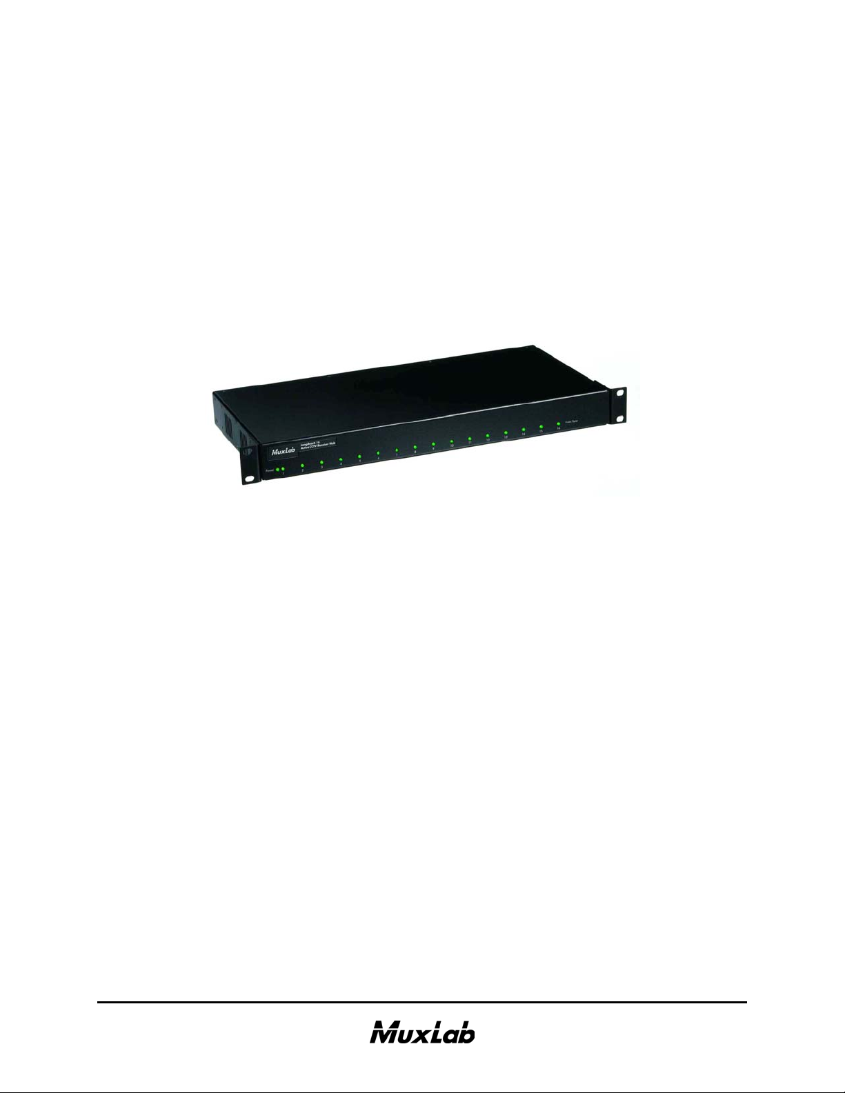
VideoEase™ LongReach™16
Active CCTV Receiver Hub
(500120,500121,500122,500123)
Installation Guide
P/N: 94-000369-C, SE-000405-C
Page 2

© MuxLab Inc. LongReach 16 Active CCTV Receiver Hub Installation Guide
Pag
Copyright Notice :
Copyright © 2004-2008 MuxLab Inc. All rights reserved.
Printed in Canada. No part of this publication may be reproduced, stored in a retrieval
system, or transmitted in any form or by any means, electronic, mechanical,
photocopying, recording, or otherwise without prior written permission of the author.
Trademarks :
MuxLab, VideoEase and LongReach are registered trademarks of MuxLab Inc.
e 2
Page 3

© MuxLab Inc. LongReach 16 Active CCTV Receiver Hub Installation Guide
Pag
Table of Contents
1. Overview ........................................................................................................................4
1.1. Description........................................................................................................4
1.2. Features.............................................................................................................4
2. Technical Specifications ...............................................................................................5
3. Installation Procedure ..................................................................................................6
3.1. Parts List ...........................................................................................................6
3.2. Product Overview .............................................................................................6
3.3. Pre-Installation Checklist .................................................................................7
3.4. Physical Installation..........................................................................................8
3.5. Installation Procedure – UTP/UTP Version .....................................................9
3.6. Installation Procedure – UTP/Coax Version ..................................................11
4. Troubleshooting ..........................................................................................................13
5. Product Warranty Policy ...........................................................................................14
e 3
Page 4
© MuxLab Inc. LongReach 16 Active CCTV Receiver Hub Installation Guide
Pag
1.
Overview
1.1. Description
The LongReach 16 is a 16-port Active CCTV Receiver Hub that provides a
centralized cabling solution for medium and large CCTV installations via
copper twisted pair.
The LongReach 16 features Automatic Gain Control for picture brightness,
sharpness and contrast, thereby helping to reduce on-site service calls. The
LongReach 16 supports up to 4,500 ft (1,371m) via Category 5/6 twisted pair
cable when used in conjunction with MuxLab’s passive CCTV Baluns (p/n
500000, 500009, 500022 and 500023) at the camera end.
The LongReach 16 automatically adjusts the brightness, sharpness and color
intensity of the video signal based on the actual cable conditions such as cable
grade, distance, environmental effects on the cable, etc. Any further
enhancements to the image may be made at the camera, monitor, multiplexer
or DVR. The product requires a floating 24VAC, 40VA power transformer
(included) and connects directly to the DVR or CCTV multiplexer.
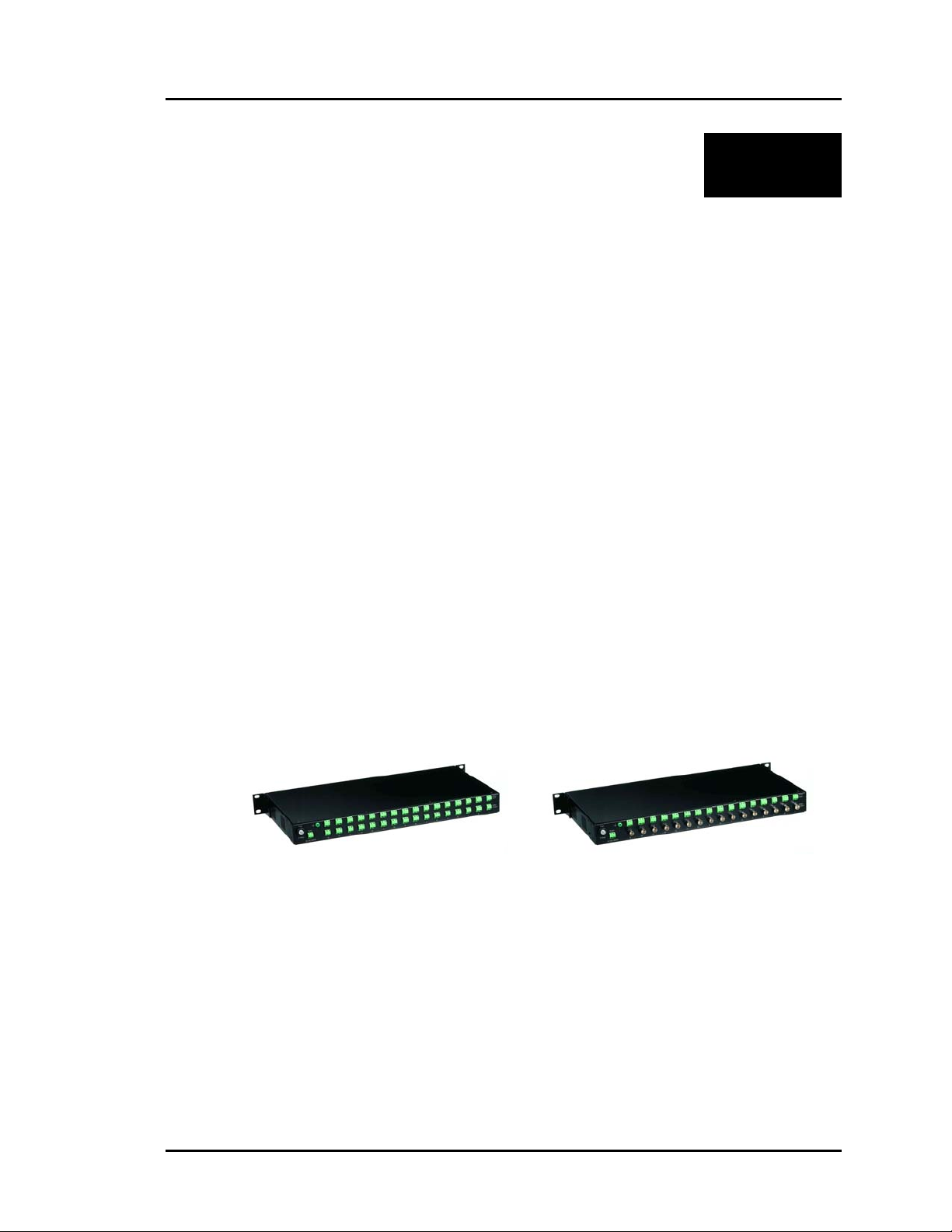
There are two models as shown in the photos below; The 500120 and the
500122. The 500120 features UTP on both input and output for installation in
remote telecom or wiring rooms. The 500122 features UTP on the input and
coax on the output for installation next to the central monitoring (DVR or
multiplexer) equipment.
1.2. Features
Up to 4,500 ft via Cat 5/6 UTP with passive CCTV Balun at camera.
Automatic Gain Control for brightness and sharpness.
Ground Loop Blocking up to +/- 50V
Diagnostic LEDs
Adjustable for rackmount, wallmount or desktop
Works with passive CCTV Baluns (p/n 500000, 500009, 500022, 500023)
Requires floating 24VAC, 60 VA power transformer (included)
1 year warranty
500120 500122
e 4
Page 5

© MuxLab Inc. LongReach 16 Active CCTV Receiver Hub Installation Guide
Pag
2.
Technical Specifications
Environment
Devices
Transmission
Bandwidth
Input
Output
Insertion Loss
Return Loss
Common Mode Rejection
Ratio
Maximum Distance via Cat
5/6 UTP*
Automatic Gain Control (AGC)
LED Indicators
Cable – UTP
Cable – BNC
Connectors*
*reverse polarity sensitive.
Compatible Baluns
Power Consumption – Max.
Power Transformer (Included)
Video Ground Loop Isolation
Fuse Rating
Temperature
Enclosure
Mounting
Dimensions
Weight
Regulatory
Warranty
Order Information
CCTV equipment for security and surveillance. RS-343 (RS-170) NTSC, PAL
CCTV cameras, DVR, IP camera encoders, monitors, switchers, multiplexers
and other CCTV equipment.
Transparent to the user
DC to 4.5 MHz.
1.5 Vp-p max, 100Ω, balanced
1.1 Vp-p, ± 1 dB, 75Ω, unbalanced
-14 dB minimum for luma, -60 dB minimum for chroma.
Determined by Automatic Gain Control.
Greater than 15 dB over the frequency range
Greater than 40 dB @ 3.85 MHz
NTSC: Camera to Hub: 4,000 ft (1,219m); Hub to DVR:500 ft (152m).
Total:4,500’ (1,371m)
PAL: Camera to Hub: 3,000 ft (914m); Hub to DVR: 350 ft (107m). Total:
3,350’ (1,021m).
*Longer distances may be achieved when connected directly to a CCTV
monitor.
Automatic Gain Control for sharpness and luminosity.
Power: One (1) green LED. Video Sync: Sixteen (16) green LEDs.
24 gauge or lower solid copper twisted pair wire impedance: 100 ohms at 1
MHz. Maximum capacitance: 20 pf/foot. Attenuation: 6.6 dB/1000 ft at 1
MHz
Impedance: 75 ohms at 1 MHz (RG59/U or RG6).
Video In from cameras: Sixteen (16) 2-pole screw terminals
Video Out to DVR: Sixteen (16) 2-pole screw terminals or sixteen (16) BNC-F
Ground: One (1) chassis ground lug
500000, 500009, 500021, 500022, 500023
40W RMS max. @ 24VAC RMS typical (floating; +15%, -10%)
North America: 110V/24VAC/60VA. Europe: 220-240/24VAC/70VA
± 50V max permanent voltage. ±100V max surge for 3 seconds
3A
Operating: 0° to 40°C. Storage:-20° to 85°C. Humidity: up to 95% non-cond.
Black
Rack mount (factory default). Removable brackets for wall mount or desktop
installation. Rubber stand-offs included for desktop installation.
19” x 8.6” x 1.75” (48.3 x 21.7 x 4.4 cm)
4.4 lbs (2 kg)
FCC and CE
1 year
500120 LongReach 16 Active CCTV Hub, UTP/UTP, 110V/24VAC
500121 LongReach 16 Active CCTV Hub, UTP/UTP, 220-240V/24VAC
500122 LongReach 16 Active CCTV Hub, UTP/Coax, 110V/24VAC
500123 LongReach 16 Active CCTV Hub, UTP/Coax, 220-240V/24VAC
e 5
Page 6

© MuxLab Inc. LongReach 16 Active CCTV Receiver Hub Installation Guide
Pag
3.
Installation Procedure
3.1. Parts List
The LongReach 16 comes with the following parts. Please verify that all
pieces are present before proceeding.
• Base Unit (Factory configuration: rack mount)
• External Power Supply 24VAC, 60VA (Europe: 70VA)
• Rubber stand-offs
• Installation Guide
3.2. Product Overview
The external connections and diagnostics of LongReach 16 are detailed in the
following diagrams. Please familiarize yourself with them before installing the
unit.
LongReach 16
Active CCTV Receiver Hub
Figure 1: Front panel, all models
Figure 2: Rear panel, UTP/UTP version
Figure 3: Rear panel: UTP/Coax version
Video
Input
Video
Input
e 6
Page 7

© MuxLab Inc. LongReach 16 Active CCTV Receiver Hub Installation Guide
Pag
3.3. Pre-Installation Checklist
Warning: Do not connect power supply to video signal or ground
terminals. Unit can be damaged and warranty will be void.
The LongReach 16 provides a centralized sixteen (16) port CCTV copper
twisted pair cabling solution.
1. The LongReach 16 is always connected to the receiver side of a CCTV
installation. For example it is connected directly to the video input ports of
a DVR, CCTV multiplexer or matrix switcher at the central monitoring
location.
2. The LongReach 16 is used in conjunction with MuxLab’s passive CCTV
Baluns (p/n 500000, 500009, 500022, or 500023). The passive CCTV
Baluns are connected at the CCTV source, which is usually the CCTV
camera.
Please note that the LongReach 16 will also work with third party vendor
baluns and CCTV cameras with built-in twisted pair baluns (balanced
output). It may be necessary to reverse the polarity of the wires first.
Distance performance may vary.
3. For best image quality and operator safety, the multiplexer or DVR should
be properly grounded. If this is not possible, then the LongReach 16
should be properly grounded via the ground screw on the unit. Please
ensure that there is a building ground available for this purpose.
Figure 4: Ground lug
4. The LongReach 16 must be powered by a floating 24VAC, 40VA min
power transformer.
5. The LongReach 16 is calibrated to work with CCTV sources that conform
to RS-343 (RS-170).
e 7
Page 8

© MuxLab Inc. LongReach 16 Active CCTV Receiver Hub Installation Guide
Pag
3.4. Physical Installation
The LongReach 16 has three mounting options; desktop, 19” rackmount or
wallmount. The product comes with two (2) mounting brackets and four (4)
rubber stand-offs to allow it to be configured for either option. The product is
factory set for rackmounting.
1. If the product is to be rackmounted in a relay rack, select the final
destination for the product and install the unit using standard rackmount
screws.
Figure 5: Rack-mount brackets
2. If the product is to be installed on a desk, then remove the rackmount
brackets with a standard Philips screwdriver and store the brackets for
future use. Peel the backing off the rubber standoffs and affix them to the
corners underneath the base of the unit.
3. If the product is to be wallmounted, remove the rackmount brackets and
install them in the wallmount position on the product as shown below.
Figure 6: Wall-mount brackets
4. Install the product on the wall using the proper mounting hardware.
e 8
Page 9

© MuxLab Inc. LongReach 16 Active CCTV Receiver Hub Installation Guide
Pag
3.5. Installation Procedure – UTP/UTP Version
The LongReach 16 is available in two models; UTP/UTP (500120,500121)
and UTP/Coax (50022, 500123). The 500120 allows the unit to be installed in
a remote wiring location away from the central monitoring equipment. The
LongReach may be installed up to 500 feet away from the DVR via Cat 5 UTP
cable. In order to install the product in this configuration, please follow the
steps below:
1. Install the LongReach 16 in its final location. Please verify that the
distance between the hub and cameras and between the hub and DVR are
within MuxLab specifications.
2. Connect a MuxLab passive CCTV Balun (MuxLab p/n 500000, 500009,
500022, 500023) to each CCTV camera video output port. Please refer to
the CCTV Balun Installation Guide for details.
3. Connect one twisted pair from each camera to one port on the rear of the
LongReach 16. Please ensure that straight-through polarity is respected
between the CCTV balun and the hub. Multipair cables are supported as
long as they are Category 5 or better.
Figure 7: Camera connection
4. Ensure that the power is turned off on DVR or mux. Install a MuxLab
passive CCTV balun on each port of the DVR. The 500009 is
recommended for this purpose.
5. Connect one twisted pair from each LongReach 16 port to each balun on
the rear of the DVR. Please ensure that straight-through polarity is
respected between the LongReach 16 and the DVR. Multipair cables are
supported as long as they are Category 5 or better.
e 9
Page 10

© MuxLab Inc. LongReach 16 Active CCTV Receiver Hub Installation Guide
Pag
Video
Input
TR
R
T
Figure 8: DVR connection, UTP/UTP version
6. Connect the floating 24VAC power transformer first to the hub and then
plug the power supply into an AC power outlet. If power is present, then
the green power LED will be ON.
7. Power on the CCTV cameras and DVR. When a video signal is detected,
the green LED on each hub port will be ON.
8. Due to the Automatic Gain Control of the LongReach 16, the camera
images may take a few seconds to stabilize. This is normal. The
LongReach 16 automatically adjusts the brightness, sharpness and color to
compensate for effects due to the cabling conditions. Use the adjustments
on the CCTV camera, DVR or monitor to fine tune the final picture.
9. If there is visible low frequency background noise (wood grain pattern) in
the picture, connect the ground lug of the LongReach 16 to a true building
ground.
10. The following diagram shows the final configuration.
Figure 9: Typical Configuration, UTP/UTP version
e 10
Page 11

© MuxLab Inc. LongReach 16 Active CCTV Receiver Hub Installation Guide
Pag
3.6. Installation Procedure – UTP/Coax Version
The LongReach 16 is available in a UTP/Coax version (500122, 500123)
where the hub is located near the central monitoring system (DVR). In order
to install the product in this configuration, please follow the steps below:
1. Perform steps 1 to 3 listed in the previous section.
2. Ensure that the power is turned off on DVR or mux.
3. Connect one coax cable from each LongReach 16 port to each video input
port on the rear of the DVR.
Video
Input
Figure 10: DVR connection, UTP/Coax version
4. Connect the floating 24VAC power transformer to the hub and plug the
power supply into an AC power outlet. If power is present, then the green
power LED will be ON.
5. Power on the CCTV cameras and DVR. When a video signal is detected,
the green LED on each hub port will be ON.
6. Due to the Automatic Gain Control of the LongReach 16, the camera
images may take a few seconds to stabilize. This is normal. The
LongReach 16 automatically adjusts the brightness, sharpness and color to
compensate for effects due to the cabling conditions. Use the adjustments
on the CCTV camera, DVR or monitor to fine tune the final picture.
7. If there is visible low frequency background noise (wood grain pattern) in
the picture, connect the ground lug of the LongReach 16 to a true building
ground.
8. The following diagram shows the final configuration.
e 11
Page 12

© MuxLab Inc. LongReach 16 Active CCTV Receiver Hub Installation Guide
Pag
Figure 11: Typical Configuration, UTP/Coax version
e 12
Page 13

© MuxLab Inc. LongReach 16 Active CCTV Receiver Hub Installation Guide
Pag
4.
Troubleshooting
The following table describes some of the problem symptoms, the probable causes and
possible solutions. If the information below does not solve the problem, the technical
support contact information can be found at the end of this section.
Picture Power
LED
No image OFF Power off
No image ON ON Wrong pin configuration Check pin configuration and verify
Picture distorted ON ON or
Picture loses
color
Picture contains
low frequency
background
noise (wood
grain pattern)
Image
occasionally
fading,
synchronization
not perfect
ON ON Exceeded distance
ON ON Poor grounding Connect ground of Active Balun to
ON ON Ground Loop Fault. i.e.
Port
LED
blinking
Probable Causes Possible Solutions
Check power supplies of CCTV
Blown fuse
EMI interference
Wires reversed on signal pair
on one side
Split pair
specifications
Lower grade UTP cable is
introducing high losses
ground differential voltage
between transmit and receive
ends exceeds 2 V DC or AC.
equipment
Remove the fuse at the rear of the
unit and replace it with one with the
same rating
straight-thru wiring
Check that wiring is not too close to
transformers and lighting ballasts
Make sure that the wires on the
signal pair are not reversed on one
side.
Check if the UTP pairs are correct
(not split)
Check DC loop resistance and
verify if distance spec is exceeded
Reduce cable length or eliminate
high-loss components
Replace cable by higher grade
true building ground
Isolate remote camera power entry
and enclosure from local ground.
Ensure that camera is secured
against static discharges (i.e.; is
inside metal, grounded cage)
When contacting your nearest MuxLab dealer or MuxLab Technical Support please have
the following information ready:
• Unit model number.
• List of tests performed.
• Cabling lay-out. Include model of
camera and DVR used, cable length
and type.
• Description of problem.
e 13
Page 14

© MuxLab Inc. LongReach 16 Active CCTV Receiver Hub Installation Guide
Pag
5.
Product Warranty Policy
Items under warranty - Company Policy
MuxLab guarantees its products to be free of defects in manufacturing and workmanship for the warranty period from the date of
purchase. If this product fails to give satisfactory performance during this warranty period, MuxLab will either repair or replace
this product at no additional charge, except as set forth below. Repair and replacement parts will be furnished on a exchange
basis and will be either reconditioned or new. All replaced parts and products become the property of MuxLab. This limited
warranty does not include repair services for damage to the product resulting from accident, disaster, misuse, abuse, or
unauthorized modifications or normal decay of battery driven devices. Batteries if included with the product, are not covered
under this warranty.
Limited warranty service can be obtained by delivering the product during the warranty period to the authorized MuxLab dealer
from whom you purchased the product, or by sending it to MuxLab. MuxLab will not accept any such product for repair without
a Return Material Authorization number (RMA#) issued by its Customer Service Department and a proof of purchase date. If
this product is delivered to MuxLab by mail, you agree to assume risk of loss or damage in transit, to prepay shipping charges to
the warranty service location, and to use the original shipping container or equivalent.
THE ABOVE LIMITED WARRANTY IS THE ONLY WARRANTY COVERING YOUR MUXLAB PRODUCT. THERE
ARE NO OTHER WARRANTIES, EXPRESSED OR IMPLIED, INCLUDING WARRANTIES OF MERCHANTABILITY
OR FITNESS FOR A PARTICULAR PURPOSE. SOME STATES DO NOT ALLOW LIMITATIONS ON IMPLIED
WARRANTIES, SO THE ABOVE LIMITATION MAY NOT APPLY TO YOU.
IF THIS PRODUCT IS NOT IN GOOD WORKING ORDER, YOUR SOLE REMEDY SHALL BE REPAIR OR
REPLACEMENT AS PROVIDED FOR ABOVE. IN NO EVENT SHALL MuxLab BE LIABLE TO YOU FOR ANY
DAMAGES, INCLUDING ANY LOSS OF PROFITS, LOST SAVINGS, OR OTHER INCIDENTAL OR CONSEQUENTIAL
DAMAGES ARISING OUT OF THE USE OF OR INABILITY TO USE THIS PRODUCT, EVEN IF MUXLAB OR AN
AUTHORISED MuxLab DEALER HAS BEEN ADVISED OF THE POSSIBILITY OF SUCH DAMAGES; NOR WILL
MUXLAB BE LIABLE FOR ANY CLAIM BY ANY OTHER PARTY. SOME STATES DO NOT ALLOW THE
EXCLUSION OR LIMITATION OF INCIDENTAL OR CONSEQUENTIAL DAMAGES FOR CONSUMER PRODUCTS,
SO THE ABOVE LIMITATIONS OR EXCLUSIONS MAY NOT APPLY TO YOU. THIS WARRANTY GIVES YOU
SPECIFIC LEGAL RIGHTS. YOU MAY ALSO HAVE OTHER RIGHTS WHICH MAY VARY FROM STATE TO STATE.
Warranty Periods
Any product found to be defective within three (3) months of invoice, including one (1) month shelf life, may be returned for
replacement by a new unit or a satisfactory repair within one (1) month of receiving any returned product. The customer must
provide MuxLab with the serial number and proof of purchase of the defective unit being returned. All R.M.A.’s issued are
subject to inspection by MuxLab, and will be returned to customer if not properly package – units must be returned in original
container or equivalent. MuxLab will not accept any such product for repair without an authorization for its Technical Support
department and without a return authorization number issued by MuxLab Customer Service department. For credit & replace
R.M.A., customer will be liable to pay replacement invoice if defective products are not returned.
Product more than six months old, including shelf life.
The defective unit must be returned prepaid to MuxLab and then the unit will be repaired or if repair is not possible, replaced by
an equivalent unit and returned to the customer within one (1) month of receiving any returned product.. There is no charge for
repair (parts and labor) during the full warranty period.
Items Defective and not under Warranty
For products which are no longer under warranty the policy is repair and return. An amount of 25% of the products published
list price at the time of purchase will be charged. Customer must issue a purchase order to cover the cost of repair.
Each unit will be returned to the customer within one (1) month from receipt of the unit by MuxLab. The defective unit must be
returned prepaid to MuxLab. The repaired unit will be returned to the customer FOB MuxLab. The repaired unit has a 90 day
warranty.
e 14
Page 15

© MuxLab Inc. LongReach 16 Active CCTV Receiver Hub Installation Guide
Pag
e 15
Page 16

© MuxLab Inc. LongReach 16 Active CCTV Receiver Hub Installation Guide
Pag
Tel.: (+1) 514 905-0588 Fax: (+1) 514 905-0589
Toll Free (North America): 877 689-5228
URL: www.muxlab.com
E-mail: videoease@muxlab.com
e 16
 Loading...