

Page 1
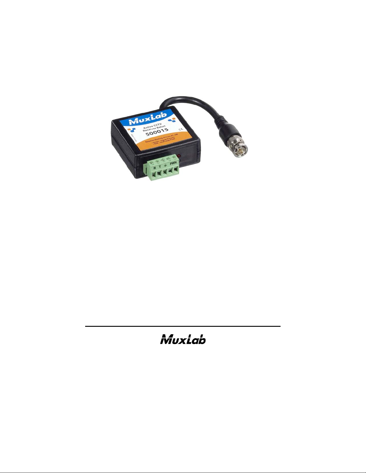
Active CCTV Receiver Balun
500015
Installation Guide
P/N: 94-000304-C SE-000266-C
Page 2

© MuxLab Inc. Active CCTV Receiver Balun Installation Guide
Pag
Copyright Notice:
Copyright © 2009 MuxLab Inc. All rights reserved.
Printed in Canada. No part of this publication may be reproduced,
stored in a retrieval system, or transmitted in any form or by any
means, electronic, mechanical, photocopying, recording or
otherwise without prior written permission of the author.
Trademarks:
MuxLab is a registered trademark of MuxLab Inc.
e 2
Page 3

© MuxLab Inc. Active CCTV Receiver Balun Installation Guide
Pag
Table of Contents
1. Overview.........................................................................4
1.1. Description........................................................4
1.2. Features.............................................................5
2. Technical Specifications................................................6
3. Installation Procedure...................................................7
3.1. Pre-Installation Checklist .................................7
3.2. Installation Procedure.......................................9
4. Troubleshooting...........................................................12
4.1. Technical Support Information.......................13
5. Product Warranty Policy............................................14
e 3
Page 4

© MuxLab Inc. Active CCTV Receiver Balun Installation Guide
Pag
1.
Overview
1.1. Description
The Active CCTV Receiver Balun (Active Balun)
allows CCTV video signals to be transmitted up to 1
mile (1.6 km) via a Category 5E/6 twisted pair cable
when used in conjunction with MuxLab’s passive
CCTV Balun (500000 or 500009) at the camera end.
The Active Balun features Automatic Gain Control
(AGC) and Ground Loop Blocking (GLB) for reliable
and stable image quality. Once installed, no adjustments
to the Active Balun are needed.
The Active Balun automatically adjusts the brightness,
sharpness and color intensity of the video signal based
on the actual cable conditions such as cable grade,
distance, environmental effects on the cable, etc. Once
installed, there is no further need to go on-site to check
the video signal. Any further enhancements to the image
may be made at the camera, monitor, multiplexer or
DVR. The product requires a 24V, 2W AC power
supply (not included) and connects directly to the video
multiplexer or switcher. It features screw terminals with
built-in strain relief for ease of installation.
e 4
Page 5

© MuxLab Inc. Active CCTV Receiver Balun Installation Guide
Pag
1.2. Features
Plug-and-Play: DDC1/DDC2 compliant
Up to 1 mile via Cat 5E/6 UTP with passive CCTV
Balun at camera
Automatic Gain Control for brightness, sharpness and
color
Ground Loop Blocking
Surge suppression
Auto-resetting fuse
Diagnostic LEDs
Connects directly to CCTV receiver equipment
Works with passive CCTV Baluns (500000 & 500009)
Requires floating 24V, 2W AC power supply (not
included)
1 year warranty
e 5
Page 6

© MuxLab Inc. Active CCTV Receiver Balun Installation Guide
Pag
2.
Technical Specifications
Environment
Devices
Transmission
Bandwidth
Input
Output
Insertion Loss
Return Loss
Common Mode Rejection
Ratio (CMRR)
Maximum Distance
Color or Black & White
LED Indicators
Cable:
Cat 5E/6 UTP/STP
Cable: BNC
Input Connectors
Output Connector
Power
Video IN/OUT Surge
protection
AC/DC power surge
protection
Built-In Fuse Protection
Temperature
Enclosure
Mounting
Regulatory
Warranty
Order Information
CCTV equipment for security and surveillance. RS-343 (RS-170)
CCTV cameras , monitors, DVR, switchers, multiplexers and other
CCTV equipment.
Transparent to the user
DC to 4.5 MHz
1.5 Vp-p max, 100 ohms, balanced
1.1 Vp-p, ±1 dB, 75 ohms, unbalanced
Determined by Automatic Gain Control.
Luma: -14 dB minimum Chroma: -60 dB minimum
Greater than 15 dB over the frequency range
Greater than 40 dB at 3.85 MHz
Category 5E/6 UTP/STP: 1 mile (1.6 km)
Green (Dim): Power
Green (Bright): Video Signal and AC power
Red: Ground Loop Fault
24 gauge or lower solid copper twisted pair wire
Impedance: 100 ohms at 1 MHz
Maximum capacitance: 20 pf/ft
Attenuation: 6.6 dB/1,000 ft at 1 MHz
Impedance: 5 ohms at 1 MHz (RG59/U or RG6)
Video: Two (2) screw terminals; reverse polarity sensitive
Power: Two (2) screw terminals
Ground: One (1) screw terminal
Video: Male BNC with 5” coax lead
24V (AC or DC) floating ±20%, 110 mA RMS typical, 3W RMS max.
±1.5V max permanent voltage positive or negative pulse, 3V max. 1
ms
Above 30 VAC RMS or 42 VDC
Auto-resetting upon power off. Not user serviceable.
Operating: 0° to 45°C Humidity: Up to 95% non-condensing
Storage: -20° to 85°C
Fire retardant plastic (black)
Dimensions: 2.40” x 2.25” x 1.00” plus 5” coax lead
Velcro pad for optional surface mounting
FCC, CE
1 year
500015 Active CCTV Receiver Balun
e 6
Page 7

© MuxLab Inc. Active CCTV Receiver Balun Installation Guide
Pag
3.
Installation Procedure
3.1. Pre-Installation Checklist
Warning: Do not connect power supply to video signal
or ground terminals. Unit can be damaged and
warranty will be void.
The Active CCTV Receiver Balun is used to provide
extended distance via a copper twisted pair. Before
installing the product, please verify the following
checklist to ensure that installation takes place
smoothly.
1. The Active Balun is always connected to the
receiver side of a CCTV installation. For example, it
is connected directly to the video input ports of the
CCTV multiplexer, DVR or matrix switcher at the
central monitoring location.
2. The Active Balun is used in conjunction with
MuxLab’s passive CCTV Balun (500009 or
500000). The passive CCTV Balun is connected at
the CCTV source, which is usually the CCTV
camera.
3. For best image quality and operator safety, the
multiplexer or DVR should be properly grounded. If
this is not possible, then the Active CCTV Balun
should be properly grounded. Please ensure that
there is a building ground available. Note: If more
e 7
Page 8

© MuxLab Inc. Active CCTV Receiver Balun Installation Guide
Pag
than one Active Balun is connected to the same
multiplexer, only one balun needs to be properly
grounded.
4. The Active Balun must be powered by a 24V, 2W
AC power supply (not supplied with the product).
5. The Active Balun is calibrated to work with CCTV
sources that conform to RS-343 (RS-170).
e 8
Page 9

© MuxLab Inc. Active CCTV Receiver Balun Installation Guide
Pag
3.2. Installation Procedure
1. Connect the passive CCTV Balun (500000 or
500009) to the CCTV camera video output port.
2. Connect one twisted pair to the passive CCTV
Balun. If the balun is the 500009, use a small flathead screwdriver. If the balun is the 500000, crimp
an RJ45 modular plug to the end of the cable,
ensuring that Pins 7 & 8 of the RJ45 are connected
to a twisted pair.
3. Identify the screw terminals on the Active Balun.
Warning: Do not connect power supply to video signal
or ground terminals. Unit can be damaged and
warranty will be void.
4. Ensure that the power is off on the CCTV
multiplexer or DVR. Connect the Active Balun to
the appropriate video input port.
5. Connect the two power wires from the 24 VAC
supply. If power is present, then the green LED will
be ON and dim. Multiple Active CCTV Baluns may
be powered from the one 24 VAC power supply.
Consult the power rating of the Active Balun in the
Technical Specifications Section on page 6 to
e 9
Page 10

© MuxLab Inc. Active CCTV Receiver Balun Installation Guide
Pag
determine how many units may be powered from
one supply.
6. Using a small flat-head screwdriver, connect one
twisted pair for video. Please note that the baluns are
polarity sensitive. Connect Ring (R) to Ring (R) and
Tip (T) to Tip (T) as indicated by the label on each
balun.
7. Power on the CCTV system. When a video signal is
detected, the green LED on the Active Balun will
change from dim to bright.
8. Due to the Automatic Gain Control of the Active
Balun, the camera image may take a few seconds to
stabilize. This is normal. The Active Balun
automatically restores the video camera signal to its
original quality, compensating for effects due to the
presence of a UTP cable and electrical noise. Use the
monitor’s standard controls to fine tune the final
picture.
9. If there is visible low frequency background noise
(wood grain pattern) in the picture, connect the
ground wire of the Active Balun to a true building
ground.
10. If there is a severe ground loop problem in which the
voltage differential between the camera and the
e 10
Page 11

© MuxLab Inc. Active CCTV Receiver Balun Installation Guide
Pag
Active Balun exceeds 1.5 VDC, the red LED will
light up. If this occurs and there is image distortion,
correct the problem by installing additional ground
loop blocking equipment or eliminating the voltage
differential. If there is no image distortion, the
Active Balun will continue to function normally and
there is no need to take corrective action.
11. The following diagram illustrates a typical
configuration.
12. The Active Balun is equipped with resettable fuses
to protect the circuitry. In the event of a power
surge, the fuse(s) will trip and the green LED will
dim. In order for the fuse(s) to reset, the power to the
Active Balun must be turned OFF for 2-3 minutes.
The fuse(s) will then reset and the power can be
turned on again.
e 11
Page 12

© MuxLab Inc. Active CCTV Receiver Balun Installation Guide
Pag
4.
Troubleshooting
The following table describes some of problem symptoms,
probable causes, and possible solutions. If the information below
does not solve the problem, the technical support contact
information can be found at the end of this section.
Picture Green LED Red LED Probable Cause Possible Solutions
OFF OFF •Power off
•Wrong pin
configuration
•Fuse tripped due to
power surge
•EMI interference
•Wires reversed on
signal pair on one
side
•Split pair
•Exceeded distance
specifications
•Lower grade UTP
cable is introducing
high losses
•Ground Loop Fault
(ground differential
voltage between
transmit & receive
ends exceeds 2
VDC or AC)
Picture distorted
Picture loses
color
Picture contains
low frequency
background
noise (wood
grain pattern)
Image
occasionally
fading,
synchronization
not perfect
Dim OFF
Dim OFF
Bright or
blinking
Bright OFF
Bright OFF •Poor grounding
Bright
OFF
ON or
blinking
•Check power supplies of CCTV
equipment.
•Check pin configuration and verify
straight-thru wiring.No image
•Turn power off. Wait 2-3 minutes.
Turn power on. Investigate cause of
power surge.
•Check that wiring is not too close to
transformers and lighting ballasts.
•Make sure that the wires on the
signal pair are not reversed on one
side.
•Check if the UTP pairs are correct
(not split).
•Check DC loop resistance and
verify if distance spec is exceeded.
•Reduce cable length or eliminate
high-loss components
•Replace cable by one of higher
grade.
•Connect ground of Active Balun to
true building ground.
•Isolate remote camera power
entry and enclosure from local
ground.
•Ensure that camera is secured
against static discharges (i.e., is
inside a metal, grounded cage).
e 12
Page 13

© MuxLab Inc. Active CCTV Receiver Balun Installation Guide
Pag
4.1. Technical Support Information
When contacting your nearest MuxLab dealer or
MuxLab Technical Support, please have the following
information ready:
Unit model number
Cabling layout. Include camera and multiplexer/DVR
used (with model numbers), estimated cable lengths
(between the equipment), and type of cable used (UTP,
STP, 4-pair, multipair, category)
Description of problem
List of tests performed
e 13
Page 14

© MuxLab Inc. Active CCTV Receiver Balun Installation Guide
Pag
5.
Product Warranty Policy
Items Under Warranty - Company Policy
MuxLab guarantees its products to be free of defects in manufacturing and workma nship for
the warranty period from the date of purchase. If this product fails to give satisfactory
performance during this warranty period, MuxLab will either repair or replace this product at
no additional charge, except as set forth below. Repair and replacement parts will be furnished
on an exchange basis and will be either reconditioned or new. All replaced parts and products
become the property of MuxLab. This limited warr a nty does not include repair services for
damage to the product resulting from accident, disaster, misuse, abuse, or unauthorized
modifications or normal decay of battery driven devices. Batteries, if included with the
product, are not covered under this warranty.
Limited warranty service can be obtained by delivering the product during the warranty period
to the authorized MuxLab dealer from whom you purchased the product, or by sending it to
MuxLab. MuxLab will not accept any such product for repair without a Return Material
Authorization number (RMA#) issued by its Customer Service Department and a proof of
purchase date. If this product is delivered to MuxLab by mail, you agree to assume risk of loss
or damage in transit, to prepay shipping charges to the warranty service location, and to use the
original shipping container or equivalent.
THE ABOVE LIMITED WARRANTY IS THE ONLY WARRANTY COVERING YOUR
MUXLAB PRODUCT. THERE ARE NO OTHER WARRANTIES, EXPRESSED OR
IMPLIED, INCLUDING WARRANTIES OF MERCHANTABILITY OR FITNESS FOR A
PARTICULAR PURPOSE. SOME STATES DO NOT ALLOW LIMITATIONS ON
IMPLIED WARRANTIES, SO THE ABOVE LIMITATION MAY NOT APPLY TO YOU.
IF THIS PRODUCT IS NOT IN GOOD WORKING ORDER, YOUR SOLE REMEDY
SHALL BE REPAIR OR REPLACEMENT AS PROVIDED FOR ABOVE. IN NO EVENT
SHALL MuxLab BE LIABLE TO YOU FOR ANY DAMAGES, INCLUDING ANY LOSS
OF PROFITS, LOST SAVINGS, OR OTHER INCIDENTAL OR CONSEQUENTIAL
DAMAGES ARISING OUT OF THE USE OF OR INABILITY TO USE THIS PRODUCT,
EVEN IF MUXLAB OR AN AUTHORISED MuxLab DEALER HAS BEEN ADVISED OF
THE POSSIBILITY OF SUCH DAMAGES; NOR WILL MUXLAB BE LIABLE FOR ANY
CLAIM BY ANY OTHER PARTY. SOME STATES DO NOT ALLOW THE EXCLUSION
OR LIMITATION OF INCIDENTAL OR CONSEQUENTIAL DAMAGES FOR
CONSUMER PRODUCTS, SO THE ABOVE LIMITATIONS OR EXCLUSIONS MAY NOT
APPLY TO YOU. THIS WARRANTY GIVES YOU SPECIFIC LEGAL RIGHTS. YOU
MAY ALSO HAVE OTHER RIGHTS WHICH MAY VARY FROM STATE TO STATE.
e 14
Page 15

© MuxLab Inc. Active CCTV Receiver Balun Installation Guide
Pag
Warranty Periods
Any product found to be defective within three (3) months of invoice, including one (1) month
shelf life, may be returned for replacement by a new unit or a satisfactory repair within one (1)
month of receiving any returned product. The customer must provide MuxLab with the serial
number and proof of purchase of the defective unit being returned. All R.M.A.’s issued are
subject to inspection by MuxLab, and will be returned to customer if not properly package –
units must be returned in original container or equivalent. MuxLab will not accept any such
product for repair without an authorization for its Technical Support department and without a
return authorization number issued by MuxLab Customer Service department. For credit &
replace R.M.A., customer will be liable to pay replacement invoice if defective products are not
returned.
Product more than six months old, including shelf life.
The defective unit must be returned prepaid to MuxLab and then the unit will be repaired or if
repair is not possible, replaced by an equivalent unit and returned to the customer within one
(1) month of receiving any returned product. There is no charge for repair (parts and labor)
during the full warranty period.
Items Defective and not under Warranty
For products which are no longer under warranty the policy is repair and return. An amount
of 25% of the products published list price at the time of purchase will be charged. Customer
must issue a purchase order to cover the cost of repair.
Each unit will be returned to the customer within one (1) month from receipt of the unit by
MuxLab. The defective unit must be returned prepaid to MuxLab. The repaired unit will be
returned to the customer FOB MuxLab. The repaired unit has a 90 day warranty.
e 15
Page 16

© MuxLab Inc. Active CCTV Receiver Balun Installation Guide
Pag
MuxLab Inc.
8495 Dalton Road, Mount Royal, Quebec, Canada. H4T 1V5
Tel: (514) 905-0588 Fax: (514) 905-0589
Toll Free (North America): (877) 689-5228
E-mail: videoease@muxlab.com URL: www.muxlab.com
e 16
 Loading...