

Page 1
HDMI 4x4 Matrix Switch
500415
Installation Guide
P/N: 94-000671-A SE-000671-A
Page 2

© MuxLab Inc. HDMI 4x4 Matrix Switch Installation Guide
Pag
Copyright Notice:
Copyright © 2011 MuxLab Inc. All rights reserved.
Copyright © 2009 Real Time Engineers Ltd.
This product uses an unmodified version of FreeRTOS V6.0.0.
Source code available at www.freertos.com
Printed in Canada. No part of this publication may be reproduced,
stored in a retrieval system, or transmitted in any form or by any
means, electronic, mechanical, photocopying, recording or
otherwise without prior written permission of the author.
Trademarks:
MuxLab is a registered trademark of MuxLab Inc.
e 2
Page 3

© MuxLab Inc. HDMI 4x4 Matrix Switch Installation Guide
Pag
Table of Contents
1. Overview .........................................................................4
1.1. Description ..............................................................4
1.2. Features ...................................................................5
2. Technical Specifications ................................................6
3. Installation Procedure ...................................................7
3.1. Parts List .................................................................7
3.2. Product Overview ...................................................8
3.3. Pre-Installation Checklist ...................................... 10
3.4. Physical Installation .............................................. 11
3.5. Installation Procedure............................................12
3.6. Port Control Operation..........................................15
3.7. Driver Setup ..........................................................17
3.8. MuxLab Control Center Software......................... 20
3.9. Ethernet Web Interface .........................................25
3.10. Cascadability......................................................... 29
4. Troubleshooting ...........................................................32
5. Appendix.......................................................................34
A. ASCII Command Set.............................................34
B. Serial Port and LAN Setup....................................39
C. Infrared Remote Control Codes ............................41
6. Product Warranty Policy ............................................42
e 3
Page 4
© MuxLab Inc. HDMI 4x4 Matrix Switch Installation Guide
Pag
1.
Overview
1.1. Description
The MuxLab 500415 HDMI 4x4 Matrix Switch allows
four (4) HDMI sources to be switched/distributed up to
four (4) local displays and up to four (4) remote displays
via unshielded twisted pair (UTP) or shielded twisted
pair (STP) cables for cost-efficient connectivity. Remote
HDMI equipment can be connected up to 150 feet (46
meters) @ 1080p Deep Color via two (2) Cat 6 UTP
cables. The HDMI 4x4 Matrix Switch works in
conjunction with MuxLab’s HDMI Receivers (500407
or 500417).
Applications include commercial and residential AV
systems, classroom projector systems, digital signage,
boardroom systems, multi-room systems, classroom
training, retail systems, collaborative PC systems, and
medical information systems.
e 4
Page 5

© MuxLab Inc. HDMI 4x4 Matrix Switch Installation Guide
Pag
1.2. Features
UTP/STP modular RJ45 jacks on four (4) outputs.
HDMI input and HDMI local output.
IR support for remote control of all four (4) HDMI
sources.
Support for 1080p Deep Color up to 150 ft (46 m) via
Cat 6 UTP cables.
Seamless integration with MuxLab’s HDMI Receivers
(500407 or 500417).
e 5
Page 6
© MuxLab Inc. HDMI 4x4 Matrix Switch Installation Guide
Pag
2.
Technical Specifications
Environment
Devices
Transmission
Bandwidth
Signals
Connectors
HDMI Cables not included.
Maximum Distance
HDMI Switch to Display
Based upon a maximum
length of 6.6 ft (2 m) of HDMI
cable per end.
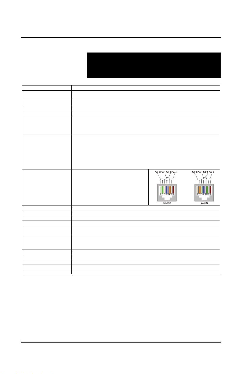
RJ45 Pin Configuration
Reverse Polarity Sensitive
Use EIA/TIA 568A or 568B
straight-through wiring
Cable
Power Supply
Compatible Receivers
Power Consumption
LED Diagnostics
Temperature
Dimensions
Weight
Regulatory
Warranty
Order Information
HDMI 1.3A
LCD and Plasma TVs, DVD and Blu-Ray players, monitors, projectors, PCs, laptops,
home theatre systems, home theater PCs, game consoles, servers that support HDMI.
Transparent to the user
Video: 225 MHz
HDMI 1.3a protocol
Source Input: Four (4) HDMI receptacles
Local Output: Four (4) HDMI receptacles
Distributed Output: Four (4) UTP/STP outputs via eight (8) RJ45S connectors for
Cat 5e Cat 6
480i/p 300 ft (91 m) 300 ft (91 m)
720p, 1080i 300 ft (91 m) 300 ft (91 m)
1080p 150 ft (46 m) 200 ft (61 m)
1080p Deep Color 90 ft (27 m) 150 ft (46 m)
NOTE: STP cables must be used in an electrically noisy environment. Also, cross-connection
reduces the effective distance depending on the grade of twisted cable used.
RJ45 A (HDMI A) RJ45 B (HDMI B)
Pin 1 (R) Pin 2 (T) Pin 1 (R) Pin 2 (T)
Pin 3 (R) Pin 6 (T) Pin 3 (R) Pin 6 (T)
Pin 4 (R) Pin 5 (T) Pin 4 (R) Pin 5 (T)
Pin 7 (R) Pin 8 (T) Pin 7 (R) Pin 8 (T)
Two (2) Cat 5e/6 UTP/STP cables (or better) required per port
One (1) 110-240V/12VDC, 2.5A power supply with three interchangeable blades
500407, 500417
30 Watts
Power (Blue)
Interconnection Matrix (Green)
Operating: 0ºC to 40ºC
Storage: -20ºC to 85ºC
Humidity: Up to 95% non-condensing
1U Rack Mountable: 19.00” x 7.50” x 1.75” (48.26 cm x 19.05 cm x 4.45 cm)
4.0 lb (1.8 kg)
FCC, CE-EMC Directive 89/336/EE, RoHS, WEEE
Two (2) years
500415: HDMI 4x4 Matrix Switch (includes four [4] IR Emitters)
Cat 5e/6 UTP/STP cabling
e 6
Page 7

© MuxLab Inc. HDMI 4x4 Matrix Switch Installation Guide
Pag
3.
Installation Procedure
3.1. Parts List
The HDMI 4x4 Matrix Switch (500415) comes with the
following parts:
Base Unit
Four (4) IR Emitters
One (1) 110-240V/12VDC, 2.5A Power Supply with
three interchangeable blades
One (1) USB Type A – Type B Cable
One (1) USB flash drive with Port Control Software
Four (4) rubber feet for set-top operation
One (1) infrared remote
Installation Guide
Please verify that all parts are present before proceeding.
e 7
Page 8
© MuxLab Inc. HDMI 4x4 Matrix Switch Installation Guide
Pag
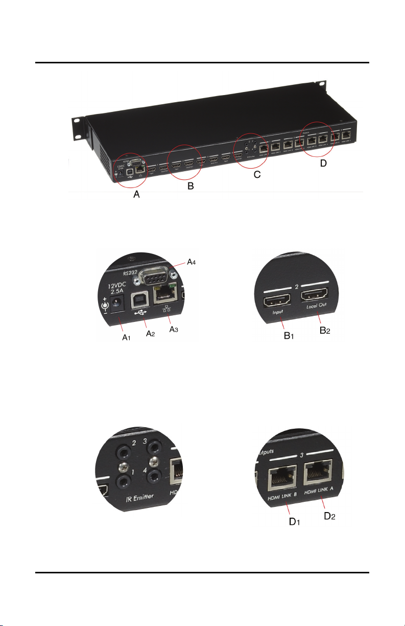
3.2. Product Overview
The external connections and connection indicators of
the HDMI 4x4 Matrix Switch are detailed in Figure 1
and Figure 2. Please familiarize yourself with them
before installing the unit.
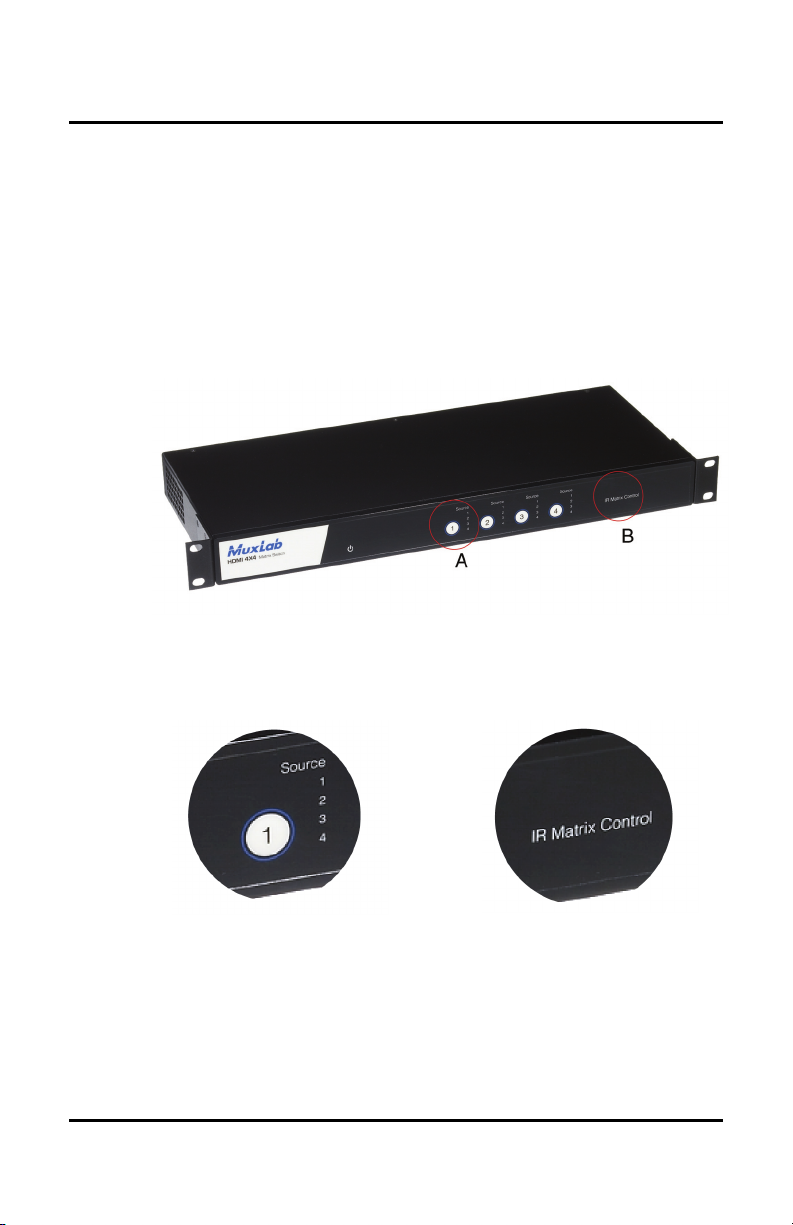
Figure 1: Front Panel of Matrix Switch
Detail A Detail B
Display Push Button IR Matrix Control LED
& HDMI Source LEDs
e 8
Page 9
© MuxLab Inc. HDMI 4x4 Matrix Switch Installation Guide
Pag
Figure 2: Back Panel of Matrix Switch
Detail A Detail B
A1 = Power Supply Port B1 = HDMI Input
A
= USB Port B2 = HDMI Local Out
2
A
= Ethernet Port
3
A
= RS232 Port
4
Detail C Detail D
IR Emitter Jacks D1 = RJ45 Output Jack B
D2 = RJ45 Output Jack A
e 9
Page 10

© MuxLab Inc. HDMI 4x4 Matrix Switch Installation Guide
Pag
3.3. Pre-Installation Checklist
The HDMI 4x4 Matrix Switch provides a centralized
HDMI switching center via copper UTP/STP cables.
1. The HDMI 4x4 Matrix Switch is used in conjunction
with MuxLab’s HDMI Receivers (500407 or
500417).
2. The HDMI 4x4 Matrix Switch is typically installed
in a remote telecom room and is connected to the
HDMI video source and display devices via Cat 5e/6
UTP/STP cables. A MuxLab HDMI Receiver is
installed at each HDMI display to support the
connection to the Matrix Switch via Cat 5e/6 cables.
e 10
Page 11
© MuxLab Inc. HDMI 4x4 Matrix Switch Installation Guide
Pag
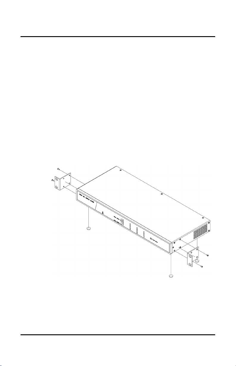
3.4. Physical Installation
MuxLab’s HDMI 4x4 Matrix Switch comes with
mounting brackets for standard 19” rack mounting.
Select the final destination for the product and install the
unit using standard rack-mount screws.
For set-top installation, the L-brackets on the side of the
unit may be removed and the included rubber feet
placed on the bottom of the unit. When removing the Lbrackets, be careful to keep and reinstall the four screws
on each side of the unit.
Figure 3: Procedure for Set-Top Installation
e 11
Page 12

© MuxLab Inc. HDMI 4x4 Matrix Switch Installation Guide
Pag
3.5. Installation Procedure
In order to install the product, please follow the steps
below:
1. Place the HDMI 4x4 Matrix Switch in its final
location.
2. Ensure that the power is turned off on the HDMI
source and displays.
3. In order to distribute the HDMI, one (1) HDMI
Receiver (500407 or 500417) must be connected at
each HDMI display. To install the Receivers,
complete Steps 4, 5, and 6.
4. Identify the pin configuration of the Receivers. Two
(2) Cat 5e/6 UTP/STP cables are required for each
HDMI connection. The pin configuration follows the
EIA/TIA 568A/B standard. The HDMI Receiver is
reverse-polarity sensitive. Please ensure that the
wiring is straight-through (Ring to Ring, Tip to Tip),
and that the two HDMI twisted pair links are not
crossed.
5. Using an HDMI cable (not supplied), plug each
HDMI source to an HDMI input of the Matrix
Switch.
6. Using an HDMI cable (not supplied), connect an
HDMI Receiver (500407 or 500417) to each HDMI
display.
7. Complete the connection between the Matrix Switch
and each HDMI display using standard straight-thru
e 12
Page 13
© MuxLab Inc. HDMI 4x4 Matrix Switch Installation Guide
Pag
Cat 5e/6 UTP/STP cables and connecting hardware,
terminated on RJ45 plugs at both ends. Ensure that
there are no split pairs or taps.
8. Optional: Local televisions may be connected using
HDMI cables (not supplied).
9. Power up the Receivers and HDMI equipment first.
10. Connect the external 12VDC power supply to the
Matrix Switch and plug the power supply into an AC
power outlet. If power is present, the blue power
LED will be ON.
11. Ensure that the source and appropriate display LEDs
are ON. Images should appear on the displays within
10 seconds. Check the image quality and refer to the
troubleshooting table in Section 4 if image quality is
unsatisfactory.
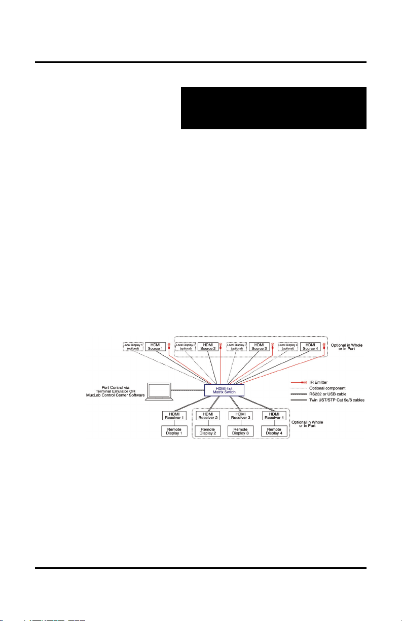
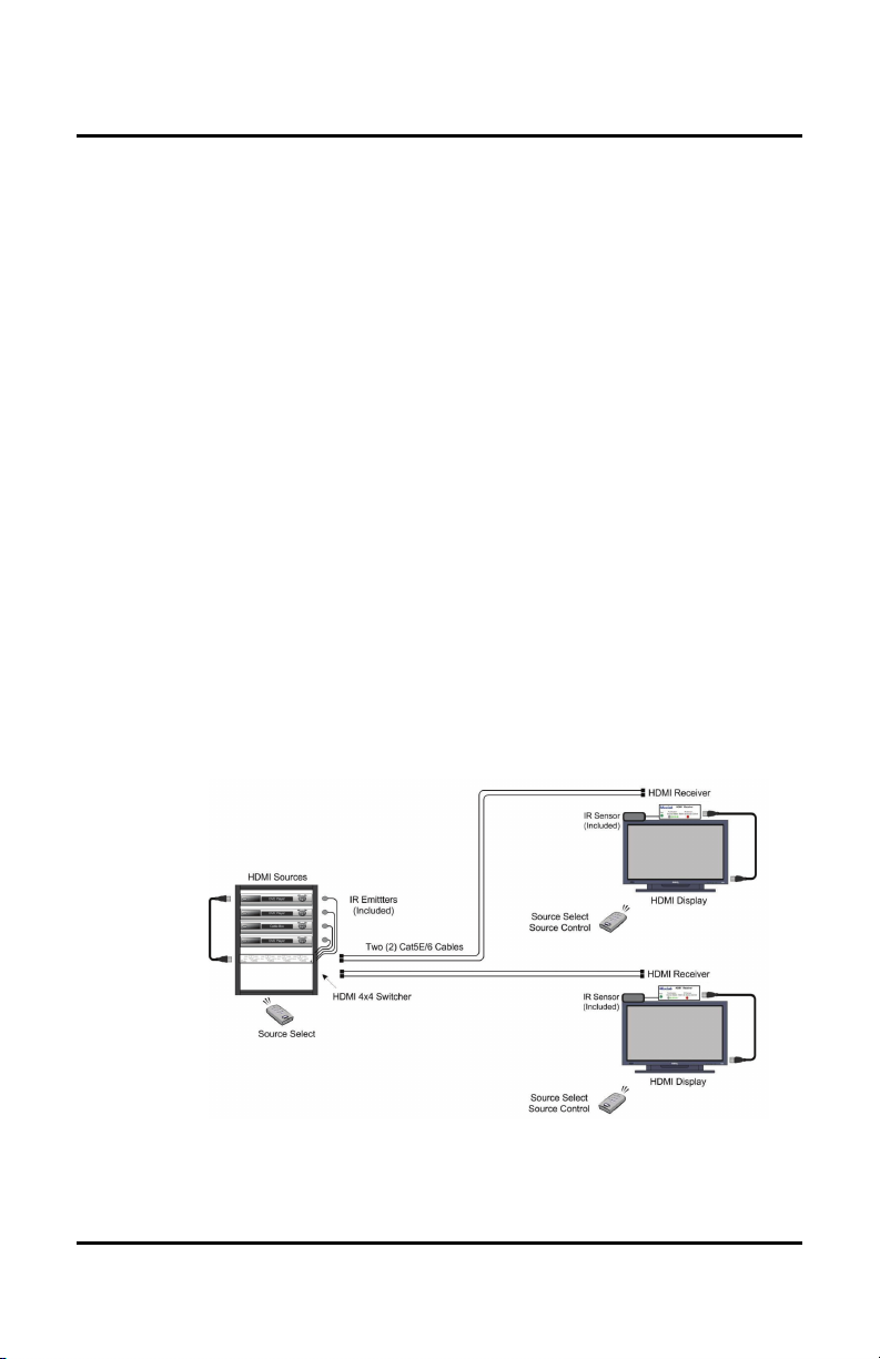
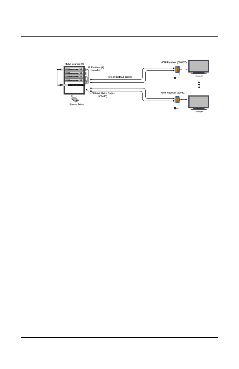
12. Figures 4 and 5 show some typical configurations:
Figure 4: Typical Configuration (I)
e 13
Page 14
© MuxLab Inc. HDMI 4x4 Matrix Switch Installation Guide
Pag
Figure 5: Typical Configuration (II)
Please note that Figure 5 is for users who do not require
control of the Matrix Switch from a remote location. In
such a case, MuxLab’s HDMI Receiver (500407) may
be used.
The IR Emitters included with the Matrix Switch are
used to control HDMI sources. Simply insert the plug of
an IR Emitter into any one of the 4 “IR Emitter” jacks
located on the back panel of the Matrix Switch. The
number of the jack (1, 2, 3, or 4) into which a specific
Emitter is plugged determines which HDMI Source that
Emitter will control. For example, an IR Emitter
plugged into IR Emitter jack 3 will control HDMI
Source 3.
For more information on installing and using IR
Emitters, please refer to MuxLab’s IR Emitter Quick
Installation Guide.
e 14
Page 15

© MuxLab Inc. HDMI 4x4 Matrix Switch Installation Guide
Pag
3.6. Port Control Operation
RS-232/USB Control
The HDMI 4x4 Matrix Switch features built-in firmware
that allows commands from an ASCII terminal to be
sent directly to the device via either a USB or RS-232
connection (not both simultaneously). If connecting with
an RS-232 cable, ensure that the cable has the straightthrough configuration shown in Figure 6.
2
3
5
DB9
Male
Figure 6: RS-232 Cable Configuration
2
3
5
DB9
Female
Port Control is performed with either the MuxLab
Control Center software, described in Section 3.7, or
with a terminal emulator such as the one available under
Windows with the ASCII Command Set described in
Appendix A. Please note that USB to RS-232 converter
cables could result in problems, depending on the
quality of the product.
e 15
Page 16

© MuxLab Inc. HDMI 4x4 Matrix Switch Installation Guide
Pag
Manual Control
The HDMI 4x4 Matrix Switch may be controlled
manually by using the push buttons located on its front
panel. Each “Display” push button controls the
particular display corresponding to its number (1, 2, 3,
or 4). By pressing on a given Display push button, the
user can choose which HDMI Source to send to that
display. The number of the HDMI Source being sent to
a particular display at any given time is indicated by an
illuminated LED next to the “Source” number (1, 2, 3,
or 4).
IR Remote Control
The Remote Control (shown on right) is divided into 4
sections, with each section controlling a particular
display. For any given display, the user
can choose which HDMI Source to send
to that display, either directly by
clicking on push buttons 1, 2, 3, or 4, or
indirectly by pressing on the left & right
arrow push buttons to cycle through
HDMI Sources. Note that when the
Remote Control is used in conjunction
with MuxLab’s HDMI Receiver
(500417), the user will only be able to
control the display which is connected
to the local HDMI Receiver.
e 16
Page 17

© MuxLab Inc. HDMI 4x4 Matrix Switch Installation Guide
Pag
3.7. Driver Setup
When interfacing a MuxLab device with Windows 2000
(or more recent) operating system, a driver setup file
will be required.
To install the MuxLab Control Center software, insert
the USB flash drive into the PC. Plug the USB cable
between the device and the PC, and power up the
device. The Found New Hardware wizard will open
(Figure 7). Select Locate and install driver software.
Figure 7: Found New Hardware Wizard
e 17
Page 18

© MuxLab Inc. HDMI 4x4 Matrix Switch Installation Guide
Pag
A new dialog box will open (Figure 8). Select Browse
my computer for driver software.
Figure 8: Found New Hardware Dialog Box
Another dialog box will open (Figure 9). Click Browse
and locate the USB flash drive. Once found, click Next.
Figure 9: Browsing for Unknown Device
e 18
Page 19

© MuxLab Inc. HDMI 4x4 Matrix Switch Installation Guide
Pag
A security window will now appear, indicating that the
driver software is unsigned (Figure 10). Select Install
this driver software anyway.
Figure 10: Windows Security
A window will appear instructing that the software for
the driver has been successfully installed (Figure 11).
Click Close. You are now ready to launch the MuxLab
Control Center software.
Figure 11: Successful Installation Dialog Box
e 19
Page 20

© MuxLab Inc. HDMI 4x4 Matrix Switch Installation Guide
Pag
3.8. MuxLab Control Center Software
MuxLab provides the user with software for operating
the HDMI 4x4 Matrix Switch via a PC. Each Matrix
Switch has 4 input ports and 4 output ports, and the
MuxLab Control Center software enables the user to
select which input port to feed to the output port.
To install MuxLab’s Control Center software, insert the
USB flash drive into the PC, open the folder, and double
click the SC-000032 file.
When running MuxLab’s Control Center software for
the first time, the main window will appear (Figure 12).
Figure 12: MuxLab Control Center Main Window
On the left is the Devices tree, which by default is
empty. A device may be a Matrix Switch or any other
software-controllable MuxLab product. For the purpose
of the following discussion, we will consider a Matrix
Switch as the device in question.
e 20
Page 21

© MuxLab Inc. HDMI 4x4 Matrix Switch Installation Guide
Pag
Once all hardware has been connected, the user must
perform the following three steps:
1. Load the Matrix Switch (automatically or manually)
2. Configure the Matrix Switch
3. Control the Matrix Switch
1. Loading the Matrix Switch
Loading consists of detecting the Matrix Switch (or any
other software-controllable MuxLab device) connected
to a PC. Loading can be done either automatically or
manually. If done automatically, every device is loaded
simultaneous by the software. If done manually, each
device must be individually loaded by the user.
Once the Matrix Switch has been successfully loaded, it
will be displayed in the Devices tree.
To load a device automatically, select Devices>Load
All Connected Devices… (Figure 13).
Figure 13: Loading All Connected Devices
e 21
Page 22

© MuxLab Inc. HDMI 4x4 Matrix Switch Installation Guide
Pag
Automatic loading detects all devices connected to the
PC, as well as the COM port on the PC to which each
device is connected.
To load a device manually, select Devices>Add
Device… This loads devices one at a time, and does not
automatically detect the COM port on the PC to which a
device is connected. This COM port assignment must be
completed in the Configure Device tab. Until this
assignment is completed by the user, the loaded device
will appear in brackets as “offline” in the Devices tree
(Figure 14).
Figure 14: Offline Device
2. Configuring a Matrix Switch
Configuring a device consists of three operations:
(i) Assigning a PC COM port to the Matrix Switch
(if Matrix Switch was loaded manually)
(ii) Naming the Matrix Switch
(iii) Naming the four input ports and the four output
ports on the Matrix Switch
e 22
Page 23

© MuxLab Inc. HDMI 4x4 Matrix Switch Installation Guide
Pag
To configure a Matrix Switch, select the device in the
Devices tree and click the Configure Device tab (Figure
15).
Figure 15: The Configure Device Tab
If the Matrix Switch has been loaded manually, a COM
port on the PC must be selected by clicking the down
arrow next to Connect Using. The user can select a
COM port and then name (or rename) the Matrix Switch
(Device Name), its source ports (under Source Port
Names), and its display ports (under Display Port
Names).
3. Choosing a Port Selection Method
Once the Matrix Switch has been loaded and configured,
it can be controlled by the user via the Port Selection
tab. This consists of selecting which of the Matrix
Switch’s source ports will be assigned to its display
ports.
e 23
Page 24

© MuxLab Inc. HDMI 4x4 Matrix Switch Installation Guide
Pag
Figure 16: The Port Selection Tab
Figure 17: Mapping Displays to Sources
e 24
Page 25

© MuxLab Inc. HDMI 4x4 Matrix Switch Installation Guide
Pag
3.9. Ethernet Web Interface
MuxLab offers users an Ethernet Web interface that
provides the same functionality as our Control Center
Software, with speeds between 10 Mbps and 100 Mbps.
For the Ethernet Web interface to function, the Matrix
Switch must first be physically connected to an Ethernet
network. To do this, locate the RJ45 Ethernet jack on
the back panel of the Matrix Switch, then connect it to
an Ethernet network using a straight UTP cable (max.
length 333 ft [100 m]). There are two LEDs at the top of
the RJ45 Ethernet jack: A yellow LED will go on if a
link is detected, and a green LED will blink if Ethernet
activity is detected.
Once the Matrix Switch has been physically connected
to an Ethernet network, go to http://AAA.BBB.CCC.DDD
(where AAA.BBB.CCC.DDD is the IP address assigned
to the device).
The home screen presents users with the option of using
a password (Figure 18).
Figure 18: Web Interface Home Screen
e 25
Page 26

© MuxLab Inc. HDMI 4x4 Matrix Switch Installation Guide
Pag
Passwords are blank by default, meaning that the user
just needs to click on Enter when logging on for the
first time.
NOTE: Users who have previously logged on and
chosen a password, but subsequently forgot it, may click
on Forgot your password? in order to retrieve it.
The main window now appears (Figure 19). It contains
four tabs and a Log out button. The Connection Status
tab is active by default.
Figure 19: Connection Tab Screen
The Connection Status tab screen allows the user to
understand how sources are mapped to displays. The
Connection On Off radio buttons on the top left of the
tab screen allows the user to halt communication
between the Web interface and the device.
The Setup tab screen (Figure 20) allows the user to
perform three kinds of operations. On the top left, the
user can name devices, sources, and ports. Please note
that names must alphanumeric and no more than 20
characters long.
e 26
Page 27

© MuxLab Inc. HDMI 4x4 Matrix Switch Installation Guide
Pag
Figure 20: Setup Tab Screen
On the bottom left, the user can change passwords
(default password is nothing).
On the top right, the user can assign an IP address in
either one of two ways:
DHCP This tells the network to assign an IP address
automatically.
Static IP This allows the user to explicitly assign an IP
address. Please note that the left-most input
fields on the Gateway and IP addresses must
be between 1 and 223 inclusively.
Once an IP address has been assigned, the user can click
on Apply Changes. If DHCP was used, the dialog box
shown in Figure 21 will appear.
Figure 21: IP Address Assigned by Network
e 27
Page 28

© MuxLab Inc. HDMI 4x4 Matrix Switch Installation Guide
Pag
If a Static IP was used, the dialog box shown in Figure
22 will appear.
Figure 22: IP Address Assigned by User
In order to determine an IP address, the user must go to
a terminal program and type ipconfig. Note that the
terminal program uses either a USB or RS-232 serial
port.
To determine if DHCP mode is enabled, the user must
type DHCP. By default, it is enabled.
e 28
Page 29

© MuxLab Inc. HDMI 4x4 Matrix Switch Installation Guide
Pag
3.10. Cascadability
HDMI 4x4 Matrix Switches may be cascaded in order to
send an HDMI signal to more than four (4) displays. In
fact by using the local output ports of the Matrix Switch,
in theory an unlimited number of Matrix Switches may
be connected in a daisy-chain configuration. This is
possible because a clean video signal is regenerated at
each Matrix Switch.
In more practical terms, up to four (4) Matrix Switches
may be cascaded to create a 4x16 matrix. These units
would typically be connected in the following way:
When cascading multiple Matrix Switches to create a 4
x n matrix, it is recommended to name the ports on
every Matrix Switch. All the input port names of the
matrices should be the same in regards to a given
source. For example, imagine an HDMI source
designated as “Blu-Ray DVD,” and connected to Input
Port 2 of the first Matrix Switch in the chain. Input Port
2 on every other Matrix Switch in the chain should also
e 29
Page 30

© MuxLab Inc. HDMI 4x4 Matrix Switch Installation Guide
Pag
be designated as “Blue-Ray DVD.” Each display port
name of every Matrix Switch must have a unique name
that represents the location of the display (e.g. “Dinner
Room, East Wall”). The name of every Matrix Switch
should also be unique and indicative of its location.
In terms of the actual physical connections required to
cascade multiple Matrix Switches, please follow the
steps below:
1. Use an HDMI cable to connect HDMI Source 1 to
Input Port 1 of the first Matrix Switch in the chain
(“Matrix Switch 1”).
2. Use an HDMI cable to connect HDMI Source 2 to
Input Port 2 of Matrix Switch 1
3. Repeat Step 2 for more HDMI sources and the
remaining input ports of Matrix Switch 1. The
HDMI sources are now all connected to Matrix
Switch 1.
4. Use STP/UTP cables to connect the Output Ports on
Matrix Switch 1 to the HDMI Receivers (500417 or
500407) located at the Remote Displays for Matrix
Switch 1. (This procedure is the same as when
connecting a Matrix Switch to Remote Displays in a
non-cascaded setup.)
Now to connect Matrix Switch 1 to the second Matrix
Switch in the chain (“Matrix Switch 2”).
5. Use an HDMI cable to connect the Local Out 1 port
on Matrix Switch 1 to Input Port 1 of Matrix Switch
2. HDMI Source 1 can now transfer signals to
Matrix Switch 2.
e 30
Page 31

© MuxLab Inc. HDMI 4x4 Matrix Switch Installation Guide
Pag
6. Use an HDMI cable to connect the Local Out 2 port
on Matrix Switch 1 to Input Port 2 of Matrix Switch
2. HDMI Source 2 can now transfer signals to
Matrix Switch 2.
7. Repeat Step 6 for any remaining HDMI source. All
HDMI sources connected to Matrix Switch 1 can
now transfer signals to Matrix Switch 2.
8. Use STP/UTP cables to connect the Output Ports on
Matrix Switch 2 to the HDMI Receivers (500417 or
500407) located at the Remote Displays for Matrix
Switch 2.
Repeat Steps 5-8 for the remaining Matrix Switches
being cascaded.
e 31
Page 32

© MuxLab Inc. HDMI 4x4 Matrix Switch Installation Guide
Pag
4.
Troubleshooting
The following table describes some of the problem symptoms, the
probable causes and possible solutions. If the information below
does not solve the problem, the technical support contact
information can be found at the end of this section.
PROBLEM POSSIBLE SOLUTIONS
No Image
No Image • Check that each display has a source selected.
No Image
No Image • Check that the HDMI source is plugged to the Matrix Switch input, not the local monitor out.
No Image • Connect the display devices directly to the HDMI source to ensure that this works.
White Dots in image
Flickering Image
Choppy Sound
Wrong Image
Appears
Not All Display
Devices Work
• Check that the Power LED (blue) is ON. If not, check power supply.
• Check that the source displays are powered.
• Check that display devices are ON and Receivers are ON.
• Check that Receivers’ Sync LED (green) is ON. Otherwise, check UTP/STP cables.
• Power down and then power up the Matrix Switch.
• Ensure that HDMI cables are less than 6 ft (1.8 m) long.
• Ensure that Receivers are powered up and work on their own.
• Ensure that Power Supplies are not mixed-up (Matrix Switch requires 2.5 A; Receivers require
500 mA).
• Verify cable lengths.
• Use STP cables if equipment is located in electrically noisy environment.
• If cascading multiple Matrix Switches, ensure that HDMI cables are less than 6 ft (1.8 m) long.
• Only one source may be connected to the Matrix Switch at any one time. MuxLab does not
support switching between input ports.
• Ensure that all cable lengths are within specification.
• Ensure that the HDMI source is outputting a signal compatible with all the display devices (try
1080i or 480p).
e 32
Page 33

© MuxLab Inc. HDMI 4x4 Matrix Switch Installation Guide
Pag
When contacting your nearest MuxLab dealer or MuxLab
Technical Support at 877-689-5228 (toll free in North America) or
(+1) 514-905-0588 (International), please have the following
information ready:
Unit model number.
Cabling layout. Please include the model of the HDMI
source and receiver, cable length and type.
Description of problem.
List of tests performed.
e 33
Page 34

© MuxLab Inc. HDMI 4x4 Matrix Switch Installation Guide
Pag
5.
Appendix
A. ASCII Command Set
Ensure that the terminal emulation program parameters
are set to the following:
BAUD Rate: 9600
Data bits: 8
Stop bits: 1
Parity: None
Flow control: None
It should be noted that commands are case sensitive and
arguments must be separated by a single space.
Characters that are not supported will be rejected by the
response: ILLEGAL CHARACTER. Commands must
be entered in the following way and ended with a
carriage return:
version
Description: Returns MuxLab product number & firmware version
Example: version
Arguments: [none]
Response: 500XXX Version Y.Y.Y
500XXX MuxLab part number
Y.Y.Y Firmware version
Example: 500415 Version 1.0.0
e 34
Page 35

© MuxLab Inc. HDMI 4x4 Matrix Switch Installation Guide
Pag
get –a
Description: Returns complete device configuration
Example: get – a
Arguments: [none]
Response: Version X.X.X
DEVICE: YY..Y
PORT1 IN: YY..Y
PORT2 IN: YY..Y
PORT3 IN: YY..Y
PORT4 IN: YY..Y
PORT1 OUT: YY..Y
PORT2 OUT: YY..Y
PORT3 OUT: YY..Y
PORT4 OUT: YY..Y
STATE PORT1: Z
STATE PORT2: Z
STATE PORT3: Z
STATE PORT4: Z
X Firmware version
YY..Y Name (up to 20 characters long)
Z Port currently selected (1, 2, 3, 4 or
0 when no port is selected)
Example: Version 1.1.0
DEVICE: R&D MATRIX
PORT1 IN: CABLE RCV 1
PORT2 IN: CABLE RCV 2
PORT3 IN: DVD
PORT4 IN: PORT4
PORT1 OUT: BAR 1
PORT2 OUT: BAR 2
PORT3 OUT: BAR 3
PORT4 OUT: DINING
STATE PORT1: 1
STATE PORT2: 2
STATE PORT3: 3
STATE PORT4: 1
e 35
Page 36

© MuxLab Inc. HDMI 4x4 Matrix Switch Installation Guide
Pag
get –n
Description: Returns the name of the device
Example: get –n
Arguments: [none]
Response: DEVICE: ZZ..Z
ZZ..Z Name (up to 20 characters long)
Example: DEVICE: MATRIX
get –p {port number} {type}
Description: Returns the name of a specific port
Example: get –p 2 o
Arguments: port number
Number of port in context (1, 2, 3, or 4)
type
Type of port in context (i for input, o for output)
Response: PORTX Y: ZZ..Z
X Port number (1, 2, 3, or 4)
Y Port type (IN for input, OUT for
output)
ZZ..Z Name (up to 20 characters long)
Example: PORT2 OUT: BAR 1
get –s {output port number}
Description: Returns the current state of a specific output port
Example: get –s 2
Arguments: output port number
Number of port in context (1, 2, 3, or 4)
Response: STATE PORTX: Y
X Port number (1, 2, 3, or 4)
Y Port currently selected (1, 2, 3, 4 or
0 when no port is selected)
Example: STATE PORT2: 1
e 36
Page 37

© MuxLab Inc. HDMI 4x4 Matrix Switch Installation Guide
Pag
set –d
Description: Resets ports and device names to default settings
Example: set –d
Arguments: [none]
Response: [Names reset to default values]
set –n {name}
Description: Sets a device’s name to a new specified name
Example: set –n R&D MATRIX
Arguments: name new specified name
Response: DEVICE: YY..Y
YY.. Y Name (up to 20 characters)
Example: DEVICE: MATRIX
set –p {port number} {type} {name}
Description: Sets the specific port’s name to a new specified name
Example: set –p 2 o Bar’s TV
Arguments: port number
Number of port in context (1, 2, 3, or 4)
type
Type of port in context (‘i’ for input, ‘o’ for output)
name
New specified name
Response: PORTX Y: ZZ..Z
X Port number (1, 2, 3, or 4)
Y Port type (IN for input, OUT for
output)
ZZ..Z Name (up to 20 characters)
Example: PORT2 OUT: Bar’s TV
e 37
Page 38

© MuxLab Inc. HDMI 4x4 Matrix Switch Installation Guide
Pag
select {output port number} {input port number}
Description: For a given output port, selects the appropriate input
port
Example: select 2 1
Arguments: output port number
The output port number (1, 2, 3, or 4)
input port number
The input port number for selection (1, 2, 3, or 4)
Response: PORTX OUT: PORTY IN SELECTED
X Output Port in context (1, 2, 3, or 4)
Y Input currently selected (1, 2, 3, or 4)
Example: PORT2 OUT: PORT1 IN SELECTED
e 38
Page 39

© MuxLab Inc. HDMI 4x4 Matrix Switch Installation Guide
Pag
B. Serial Port and LAN Setup
1. SERIAL PORT COMMANDS
Console
Description: Sets or displays the console configuration
Usage: console [-<opt> <value>]
Options: -d Default Setting
-s <9600/19200/38400/57600> Communication Speed
Example: Console Configuration
----------------------------------------------------------------
Baud Rate 9600, N, 8, 1
2. LAN COMMANDS
dhcp
Description: Sets or displays the dhcp configuration
Usage: dhcp [-<opt> <value>]
Options: -d Default Settings
-i <nnn.nnn.nnn.nnn> Server IP Address
-m <enable|disable> Power-up mode
Example: DHCP Client Configuration
----------------------------------------------------------------
Power Up Mode Enabled
ipconfig
Description: Displays the current LAN interface configuration
Usage: ipconfig
Example: Ethernet Interface Configuration
--------------------------------------------------------------- MAC Address 00A0E50000A9
IP Address 010.000.101.016
Subnet Mask 255.255.000.000
Default Gateway 010.000.101.001
e 39
Page 40

© MuxLab Inc. HDMI 4x4 Matrix Switch Installation Guide
Pag
2. LAN COMMANDS (continued)
reset
Description: Resets the unit
Usage: reset
help
Description: Get command list or command description
Usage: help <command>
<command> -?
Description: Get command list or command description
Usage: <command> -?
Example: get -?
system
Description Sets or displays the general system configuration
Usage: system [-<opt> <value>]
Options: -d Default Settings
-i <nnn.nnn.nnn.nnn> Product IP Address
-s <nnn.nnn.nnn.nnn> Subnet mask
-g <nnn.nnn.nnn.nnn> Default Gateway
Example: System Configuration
--------------------------------------------------------------- System Desription HDMI 4X4 Matrix Switch
MAC Address 00A0E50000A9
IP Address 010.000.101.016
Subnet Mask 255.255.000.000
Default Gateway 020.000.000.001
System Name Restaurant
Display 1 Name Bar Section
Display 2 Name Front Section
Display 3 Name Back Section
Display 4 Name VIP Section
Source 1 Name Dish Network
Source 2 Name Bell TV
Source 3 Name Illico
Source 4 Name Blu-Ray Player
e 40
Page 41

© MuxLab Inc. HDMI 4x4 Matrix Switch Installation Guide
Pag
C. Infrared Remote Control Codes
Custom Code: 00FF
Code (hex)
02
03
4A 1
04 2
05 3
06
08
09
15 1
51 2
52 3
00
1D
53
1A 1
59 2
40 3
16
0D
4B
5F 1
5B 2
4F 3
57
Section Button
Display 1
Display 2
Display 3
Display 4
Identification
4
4
4
4
e 41
Page 42

© MuxLab Inc. HDMI 4x4 Matrix Switch Installation Guide
Pag
6.
Product Warranty Policy
Items Under Warranty - Company Policy
MuxLab guarantees its products to be free of defects in manufacturing and workmanship for the
warranty period from the date of purchase. If this product fails to give satisfactory performance
during this warranty period, MuxLab will either repair or replace this product at no additional
charge, except as set forth below. Repair and replacement parts will be furnished on an exchange
basis and will be either reconditioned or new. All replaced parts and products become the property of
MuxLab. This limited warranty does not include repair services for damage to the product resulting
from accident, disaster, misuse, abuse, or unauthorized modifications or normal decay of battery
driven devices. Batteries, if included with the product, are not covered under this warranty.
Limited warranty service can be obtained by delivering the product during the warranty period to the
authorized MuxLab dealer from whom you purchased the product, or by sending it to MuxLab.
MuxLab will not accept any such product for repair without a Return Material Authorization number
(RMA#) issued by its Customer Service Department and a proof of purchase date. If this product is
delivered to MuxLab by mail, you agree to assume risk of loss or damage in transit, to prepay
shipping charges to the warranty service location, and to use the original shipping container or
equivalent.
THE ABOVE LIMITED WARRANTY IS THE ONLY WARRANTY COVERING YOUR
MUXLAB PRODUCT. THERE ARE NO OTHER WARRANTIES, EXPRESSED OR IMPLIED,
INCLUDING WARRANTIES OF MERCHANTABILITY OR FITNESS FOR A PARTICULAR
PURPOSE. SOME STATES DO NOT ALLOW LIMITATIONS ON IMPLIED WARRANTIES,
SO THE ABOVE LIMITATION MAY NOT APPLY TO YOU.
IF THIS PRODUCT IS NOT IN GOOD WORKING ORDER, YOUR SOLE REMEDY SHALL BE
REPAIR OR REPLACEMENT AS PROVIDED FOR ABOVE. IN NO EVENT SHALL MuxLab
BE LIABLE TO YOU FOR ANY DAMAGES, INCLUDING ANY LOSS OF PROFITS, LOST
SAVINGS, OR OTHER INCIDENTAL OR CONSEQUENTIAL DAMAGES ARISING OUT OF
THE USE OF OR INABILITY TO USE THIS PRODUCT, EVEN IF MUXLAB OR AN
AUTHORIZED MuxLab DEALER HAS BEEN ADVISED OF THE POSSIBILITY OF SUCH
DAMAGES; NOR WILL MUXLAB BE LIABLE FOR ANY CLAIM BY ANY OTHER PARTY.
SOME STATES DO NOT ALLOW THE EXCLUSION OR LIMITATION OF INCIDENTAL OR
CONSEQUENTIAL DAMAGES FOR CONSUMER PRODUCTS, SO THE ABOVE
LIMITATIONS OR EXCLUSIONS MAY NOT APPLY TO YOU. THIS WARRANTY GIVES
YOU SPECIFIC LEGAL RIGHTS. YOU MAY ALSO HAVE OTHER RIGHTS WHICH MAY
VARY FROM STATE TO STATE.
e 42
Page 43

© MuxLab Inc. HDMI 4x4 Matrix Switch Installation Guide
Pag
Warranty Periods
Any product found to be defective within three (3) months of invoice, including one (1) month shelf
life, may be returned for replacement by a new unit or a satisfactory repair within one (1) month of
receiving any returned product. The customer must provide MuxLab with the serial number and
proof of purchase of the defective unit being returned. All R.M.A.’s issued are subject to inspection
by MuxLab, and will be returned to customer if not properly package – units must be returned in
original container or equivalent. MuxLab will not accept any such product for repair without an
authorization for its Technical Support department and without a return authorization number
issued by MuxLab Customer Service department. For credit & replace R.M.A., customer will be
liable to pay replacement invoice if defective products are not returned.
Product more than six months old, including shelf life.
The defective unit must be returned prepaid to MuxLab and then the unit will be repaired or if repair
is not possible, replaced by an equivalent unit and returned to the customer within one (1) month of
receiving any returned product. There is no charge for repair (parts and labor) during the full
warranty period.
Items Defective and not under Warranty
For products which are no longer under warranty the policy is repair and return. An amount of 25%
of the products published list price at the time of purchase will be charged. Customer must issue a
purchase order to cover the cost of repair.
Each unit will be returned to the customer within one (1) month from receipt of the unit by MuxLab.
The defective unit must be returned prepaid to MuxLab. The repaired unit will be returned to the
customer FOB MuxLab. The repaired unit has a 90 day warranty.
e 43
Page 44

© MuxLab Inc. HDMI 4x4 Matrix Switch Installation Guide
Pag
MuxLab Inc.
8495 Dalton Road
Mount Royal, Quebec
Canada H4T 1V5
Tel.: +1 (514) 905-0588 Fax: +1 (514) 905-0589
Toll Free (North America): 877 689-5228
URL: www.muxlab.com
E-mail: videoease@muxlab.com
e 44
 Loading...