

Page 1
HDMI 1x4 Distribution Hub
500420
Installation Guide
P/N: 94-000663-A SE-000663-A
Page 2

© MuxLab Inc. HDMI 1x4 Distribution Hub Installation Guide
Pag
Copyright Notice:
Copyright © 2010 MuxLab Inc. All rights reserved.
Printed in Canada. No part of this publication may be reproduced,
stored in a retrieval system, or transmitted in any form or by any
means, electronic, mechanical, photocopying, recording or
otherwise without prior written permission of the author.
Trademarks:
MuxLab is a registered trademark of MuxLab Inc.
e 2
Page 3

© MuxLab Inc. HDMI 1x4 Distribution Hub Installation Guide
Pag
Table of Contents
1. Overview .........................................................................4
1.1. Description........................................................4
1.2. Features.............................................................5
2. Technical Specifications ................................................6
3. Installation Procedure ...................................................7
3.1. Parts List ...........................................................7
3.2. Product Overview .............................................8
3.3. Pre-Installation Checklist .................................9
3.4. Physical Installation........................................10
3.5. Installation Procedure .....................................11
3.6. EDID...............................................................14
3.7. Cascadability ..................................................18
4. Troubleshooting ...........................................................19
5. Product Warranty Policy ............................................21
e 3
Page 4
© MuxLab Inc. HDMI 1x4 Distribution Hub Installation Guide
Pag
1.
Overview
1.1. Description
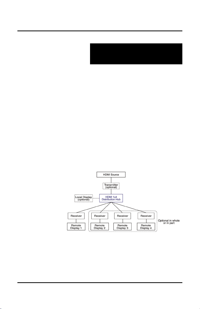
The MuxLab 500420 HDMI 1x4 Distribution Hub
allows one (1) HDMI source to be distributed to one (1)
local display and up to four (4) remote displays via
unshielded twisted pair (UTP) or shielded twisted pair
(STP) cables for cost-efficient connectivity. The 500420
also has a Local Monitor output. Remote HDMI
equipment can be connected up to 150 feet (46 meters)
@ 1080p Deep Color via two (2) Cat 6 UTP cables. The
Hub works in conjunction with MuxLab’s HDMI/IR
Transmitter Balun (500406) and Receiver Balun
(500407).
Applications include commercial and residential AV
systems, classroom projector systems, digital signage,
boardroom systems, multi-room systems, classroom
training, retail systems, collaborative PC systems, and
medical information systems.
e 4
Page 5

© MuxLab Inc. HDMI 1x4 Distribution Hub Installation Guide
Pag
1.2. Features
UTP/STP inputs and modular RJ45 jacks on four (4)
outputs.
HDMI input and HDMI local output.
IR support for remote control of HDMI source.
Support for 1080p Deep Color up to 150 ft (46 m) via
Cat 6 UTP cables.
Configuration switch to support different EDID
configurations.
Seamless integration with MuxLab’s HDMI/IR Receiver
and Transmitter Baluns.
e 5
Page 6
© MuxLab Inc. HDMI 1x4 Distribution Hub Installation Guide
Pag
2.
Technical Specifications
Environment
Devices
Transmission
Bandwidth
Signals
Connectors
HDMI Cables not included.
Maximum Distance
HDMI Source to Display
Based upon a maximum
length of 6.6 ft (2 m) of
HDMI cable per end.
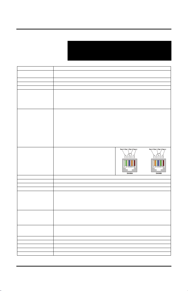
RJ45 Pin Configuration
Reverse Polarity Sensitive
Use EIA/TIA 568A or 568B
straight-through wiring
Cable
Power Supply
Compatible Baluns
Power Consumption
Configuration
Switch
LED Diagnostics
Temperature
Dimensions
Weight
Regulatory
Warranty
Order Information
HDMI 1.3A
LCD and Plasma TVs, DVD and Blu-Ray players, monitors, projectors, PCs, laptops, home
theatre systems, home theater PCs, game consoles, servers that support HDMI.
Transparent to the user
Video: 225 MHz
HDMI 1.3a protocol
Source Input: One (1) HDMI receptacle
One (1) UTP/STP input via a pair of RJ45S connectors
Local Output: One (1) HDMI receptacle
Distributed Output: Four (4) UTP/STP outputs via eight (8) RJ45S connectors for
Cat 5e Cat 6
480i/p 300 ft (91 m) 300 ft (91 m)
720p, 1080i 300 ft (91 m) 300 ft (91 m)
1080p 150 ft (46 m) 200 ft (61 m)
1080p Deep Color 90 ft (27 m) 150 ft (46 m)
NOTE: STP cables must be used in an electrically noisy environment. Also, cross-connection
reduces the effective distance depending on the grade of twisted cable used.
These distances are valid both at the UTP input AND the UTP output of the Hub.
For example, there can be a distance of 150 ft before AND 150 ft after the Hub
to distribute 1080p Deep Color via Cat 6 cabling.
RJ45 A (HDMI A) RJ45 B (HDMI B)
Pin 1 (R) Pin 2 (T) Pin 1 (R) Pin 2 (T)
Pin 3 (R) Pin 6 (T) Pin 3 (R) Pin 6 (T)
Pin 4 (R) Pin 5 (T) Pin 4 (R) Pin 5 (T)
Pin 7 (R) Pin 8 (T) Pin 7 (R) Pin 8 (T)
Two (2) Cat 5e/6 UTP/STP cables (or better) required per port
One (1) 110-240V/12VDC, 1.25A power supply with three interchangeable blades
500405/500406/500407
15 Watts
Sets Hub to support four (4) different EDID configurations (Factory Default: Position 1):
Position 1: HDMI 1.2 Basic Profile (1080i, 8-bit)
Position 2: HDMI 1.3 Profile (1080p, 12-bit Deep Color)
Position 3: Copy EDID from first display device in chain
Position 4: Adaptive EDID to dynamically support all connected display devices
Power (Blue)
HDMI Source (Orange)
HDMI Local Out (Orange)
Display Out 1 to 4 (Green)
Operating: 0ºC to 40ºC
Storage: -20ºC to 85ºC
Humidity: Up to 95% non-condensing
1U Rack Mountable: 19.00” x 6.75” x 1.75” (48.26 cm x 17.15 cm x 4.45 cm)
3.3 lbs (1.5 kg)
FCC, CE-EMC Directive 89/336/EE, RoHS, WEEE
Two (2) years
500420: HDMI 1x4 Distribution Hub (includes IR Sensor and IR Emitter)
Cat 5e/6 UTP/STP cabling
e 6
Page 7

© MuxLab Inc. HDMI 1x4 Distribution Hub Installation Guide
Pag
3.
Installation Procedure
3.1. Parts List
The HDMI 1x4 Distribution Hub (500420) comes with
the following parts:
Base Unit
One (1) IR Sensor and one (1) IR Transmitter
One (1) 110-240V/12VDC, 1.25A Power Supply with
three interchangeable blades
Four (4) rubber feet for set-top operation
Installation Guide
Please verify that all parts are present before proceeding.
e 7
Page 8
© MuxLab Inc. HDMI 1x4 Distribution Hub Installation Guide
Pag
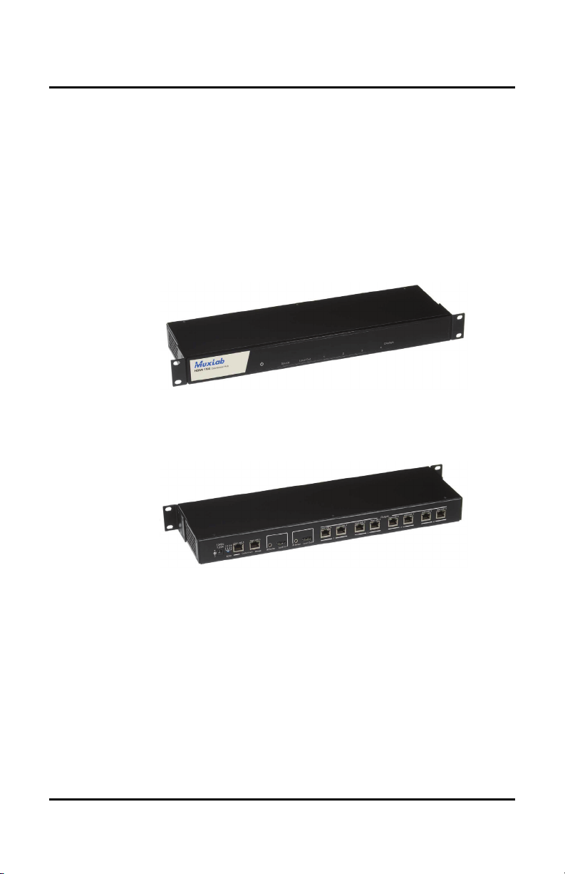
3.2. Product Overview
The external connections and diagnostic indicators of
the HDMI 1x4 Distribution Hub are detailed in the
following diagrams. Please familiarize yourself with
them before installing the unit.
Figure 1: Front Panel
Figure 2: Rear Panel
e 8
Page 9

© MuxLab Inc. HDMI 1x4 Distribution Hub Installation Guide
Pag
3.3. Pre-Installation Checklist
The HDMI 1x4 Distribution Hub provides a centralized
HDMI distribution center via copper UTP/STP cables.
1. The HDMI 1x4 Distribution Hub is used in
conjunction with MuxLab’s HDMI/IR Receiver
Balun (500407) and (optional) Transmitter Balun
(500406).
2. The HDMI 1x4 Distribution Hub is typically
installed in a remote telecom room and is connected
to the HDMI video source and display devices via
Cat 5e/6 UTP/STP cables. A MuxLab HDMI/IR
Transmitter or Receiver Balun is installed at each
HDMI device to support the connection to the Hub
via Cat 5e/6 cables.
e 9
Page 10

© MuxLab Inc. HDMI 1x4 Distribution Hub Installation Guide
Pag
3.4. Physical Installation
MuxLab’s HDMI 1x4 Distribution Hub comes with
mounting brackets for standard 19” rack mounting.
Select the final destination for the product and install the
unit using standard rack-mount screws.
For set-top installation, the L-brackets on the side of the
unit may be removed and the included rubber feet
placed on the bottom of the unit. When removing the Lbrackets, be careful to keep and reinstall the four screws
on each side of the unit.
Figure 3: Procedure for Set-Top Installation
e 10
Page 11

© MuxLab Inc. HDMI 1x4 Distribution Hub Installation Guide
Pag
3.5. Installation Procedure
In order to install the product, please follow the steps
below:
1. Place the HDMI 1x4 Distribution Hub in its final
location.
2. Ensure that the power is turned off on the HDMI
source and displays.
3. In order to distribute the HDMI, one (1) HDMI/IR
Receiver Balun (500407) must be connected at each
HDMI display. To install the Baluns, complete Steps
4, 5, and 6.
4. Identify the pin configuration of the Baluns. Two (2)
Cat 5e/6 UTP/STP cables are required for each
HDMI connection. The pin configuration follows the
EIA/TIA 568A/B standard. The HDMI/IR Receiver
Balun is reverse-polarity sensitive. Please ensure
that the wiring is straight-through (Ring to Ring, Tip
to Tip), and that the two HDMI twisted pair links are
not crossed.
5. Using an HDMI cable (not supplied), plug the
HDMI source to the HDMI input of the HDMI 1x4
Distribution Hub. If the Cat 5e/6 input is used, one
(1) HDMI/IR Transmitter Balun (500406) must be
connected to the HDMI source, and two (2) Cat 5e/6
UTP/STP cables are required. The HDMI/IR
Transmitter Balun is reverse-polarity sensitive.
Please ensure that wiring is straight-through (Ring to
e 11
Page 12

© MuxLab Inc. HDMI 1x4 Distribution Hub Installation Guide
Pag
Ring, Tip to Tip), and that the two HDMI twisted
pair links are not crossed.
6. Using an HDMI cable (not supplied), connect an
HDMI/IR Receiver Balun (500407) to each HDMI
display.
7. Complete the connection between the Hub and each
HDMI display using standard straight-thru Cat 5e/6
UTP/STP cables and connecting hardware,
terminated on RJ45 plugs at both ends. Ensure that
there are no split pairs or taps.
8. Select the desired EDID setting using the rotary dial.
9. Power up the Baluns and HDMI equipment first.
10. Connect the external 12VDC power supply to the
Hub and plug the power supply into an AC power
outlet. If power is present, the blue power LED will
be ON.
11. Ensure that the source and appropriate display LEDs
are ON. Images should appear on the displays within
10 seconds. Check the image quality and refer to the
troubleshooting table in Section 4 if image quality is
unsatisfactory.
12. The following diagrams show some typical
configurations:
e 12
Page 13

© MuxLab Inc. HDMI 1x4 Distribution Hub Installation Guide
Pag
Figure 4: Typical Configuration – UTP on Output Only
Figure 5: Typical Configuration – UTP on Input and Output
e 13
Page 14

© MuxLab Inc. HDMI 1x4 Distribution Hub Installation Guide
Pag
3.6. EDID
EDID (Extended Display Identification Data) is data
that describes the capablities of a display device to a
source device. The EDID includes the resolutions and
modes supported by the display device.
In the context of MuxLab’s HDMI 1x4 Distribution
Hub, the source device consists of the HDMI source
(typically a DVD player), and the display device
consists of the remote & local displays (typically TVs),
to which the Distribution Hub is connected.
The user sets the EDID via a four-position selector
located on the back panel of the Distribution Hub
(Figure 6). Each position communicates a different
EDID setting to the HDMI source, establishing the
resolution and mode at which the HDMI source will
send data to the display devices.
Figure 6: EDID Selector
EDID settings are described in detail on the following
two pages:
e 14
Page 15

© MuxLab Inc. HDMI 1x4 Distribution Hub Installation Guide
Pag
Position 1: HDMI 1.2
HDMI 1.2 Profile.
Maximum resolution: 1080i.
Supported color depth: 8 bits per color.
Setting is most compatible with all display devices that
support HDMI 1.2 or better.
Disables Deep Color (affects all display devices).
Prevents an HDMI source from auto-negotiating a
resolution higher than 1080i.
Supports most display devices on the market.
Position 2: HDMI 1.3
HDMI 1.3 Profile.
Maximum resolution: 1080p.
Supported color depth: 8, 10, or 12 bits per color.
HDMI source will auto-negotiate to resolution of 1080p.
Display devices that do not support 1080p will not work
at this resolution.
Position 3: Copy EDID
Copies the EDID setting from the first display device in
the chain.
Port priority is UTP/STP Outputs first (1, 2, 3, 4) THEN
Local Monitor Output.
The user must place the lowest resolution display device
on the copy port. All other displays will follow.
As with Position 1, this does not prevent the user from
manually selecting a resolution which a display device
does not support.
For the copy to take place, a display device must be
plugged in when the Distribution Hub is powered up.
Failure to do so will result in no display device working.
e 15
Page 16

© MuxLab Inc. HDMI 1x4 Distribution Hub Installation Guide
Pag
Position 4: Adaptive EDID
Analyzes the EDIDs of all the display devices in the
chain, and generates an EDID that represents them all.
Allows dynamic changes to the chain. However adding
a less robust display device to the chain will make other
display devices glitch for a fraction of a second as
settings are downgraded.
In short, Positions 1 and 2 establish generic EDID
settings that never change, regardless of the display
devices being used. Positions 3 and 4 establish EDID
settings that depend on the display devices, and are
typically more optimized for such devices.
If the user selects an EDID setting which a given display
device does not support, that device will not function.
EDID resolutions are only taken into account when an
HDMI source is auto-negotiating resolutions.
Color Depth
The color depth of a display device refers to the ability
of its constituant pixels to display color. This ability is
typically expressed in terms of bits: The greater the
number of bits, the greater the number of different
colors that a pixel can display. An 8-bit color depth (per
color channel) is standard.
The term Deep Color refers to a color depth of 30 bits or
higher (10 bits per color channel or higher in the RGB
model). Consequently, a display device with a color
depth of 30 bits or higher is known as a Deep Color
display.
e 16
Page 17

© MuxLab Inc. HDMI 1x4 Distribution Hub Installation Guide
Pag
EDID Settings and Color Depth
By setting the EDID selector to Position 1 (or by setting
the EDID selector to Position 3 and placing a non-Deep
Color display device on the copy port), the user disables
Deep Color. This will allow for greater distances via
UTP/STP cables.
Regardless of color depth mode, a display device will
always receive the highest color depth signal it can
support. This means that if the source delivers a color
signal of 10 bits per color or higher, a Deep Color
display will receive the signal unchanged, while a nonDeep Color display will receive a normal 8-bit signal.
This is transparent to the user.
e 17
Page 18

© MuxLab Inc. HDMI 1x4 Distribution Hub Installation Guide
Pag
3.7. Cascadability
HDMI 1x4 Distribution Hubs may be cascaded in order
to send an HDMI signal to more than four (4) displays.
In fact by using the Local Monitor port of the
Distribution Hub, in theory an unlimited number of
Hubs may be connected in a daisy-chain configuration.
This is possible because a clean video signal is
regenerated at each Distribution Hub.
In more practical terms, the Distribution Hubs would
typically be connected in a tree configuration:
Regardless of the configuration chosen, the EDID
selector on each Hub should be set to Position 1 or 2 in
order to avoid conflicts.
NOTE: When cascading via UTP cables, cable lengths
must be kept within 75% of maximum allowable
distance (see Technical Specifications, page 6).
e 18
Page 19

© MuxLab Inc. HDMI 1x4 Distribution Hub Installation Guide
Pag
4.
Troubleshooting
The following table describes some of the problem symptoms, the
probable causes and possible solutions. If the information below
does not solve the problem, the technical support contact
information can be found at the end of this section.
Problem Probable Solutions
No Image
No Image
No Image • Display devices may not support the current EDID setting. Set EDID selector to Position 1 or 2
No Image
No Image
White Dots in Image
or Flickering Image
or Choppy Sound
Wrong Image
Appears
Not All Display
Devices Work
• Check that the Power LED (blue) is ON. If not, check power supply
• Check that the Source LED (orange) is ON. If not, check that the HDMI source is on, and (if
applicable) that the Transmitter Balun is on
• Check that at least one Display LED (orange for Local Display, green for Remote Display) is ON.
If not, check that display devices are on and (if applicable) Receiver Baluns are on
• If Source LED and at least one Display LED is ON, check that UTP/STP cables are not inverted
• Ensure that the HDMI source is plugged to the Hub input, not the Hub output
• Power down and then power up the Hub
• Connect the display devices directly to the HDMI source to ensure that this works
• Ensure that HDMI cables are less than 6 ft long
• Ensure that Receiver/Transmitter Baluns are powered up and work on their own
• Ensure that Power Supplies are not mixed-up (Hub requires 1.25 A; Baluns require 500 mA)
• Verify cable lengths
• Use STP cables
• Set EDID selector to Position 1 or 2
• If cascading multiple hubs, ensure that UTP cable lengths are 25% less than maximum allowable
• Only one source may be connected to the Distribution Hub at any one time. MuxLab does not
support switching between input ports
• Ensure that all cable lengths are within specification
• If EDID selector is in Position 3, ensure that lowest resolution display device is connected to the
Copy Port.
• Set EDID selector to Position 1 or 2
• Ensure that the HDMI source is outputting a signal compatible with all the display devices (try
1080i or 480p). NOTE: The EDID selector does not prevent the user from choosing an
incompatible mode
e 19
Page 20

© MuxLab Inc. HDMI 1x4 Distribution Hub Installation Guide
Pag
When contacting your nearest MuxLab dealer or MuxLab
Technical Support at 877-689-5228 (toll free in North America) or
(+1) 514-905-0588 (International), please have the following
information ready:
Unit model number.
Cabling layout. Please include the model of the HDMI
source and receiver, cable length and type.
Description of problem.
List of tests performed.
e 20
Page 21

© MuxLab Inc. HDMI 1x4 Distribution Hub Installation Guide
Pag
5.
Product Warranty Policy
Items Under Warranty - Company Policy
MuxLab guarantees its products to be free of defects in manufacturing and workmanship for the
warranty period from the date of purchase. If this product fails to give satisfactory performance
during this warranty period, MuxLab will either repair or replace this product at no additional
charge, except as set forth below. Repair and replacement parts will be furnished on an exchange
basis and will be either reconditioned or new. All replaced parts and products become the property of
MuxLab. This limited warranty does not include repair services for damage to the product resulting
from accident, disaster, misuse, abuse, or unauthorized modifications or normal decay of battery
driven devices. Batteries, if included with the product, are not covered under this warranty.
Limited warranty service can be obtained by delivering the product during the warranty period to the
authorized MuxLab dealer from whom you purchased the product, or by sending it to MuxLab.
MuxLab will not accept any such product for repair without a Return Material Authorization number
(RMA#) issued by its Customer Service Department and a proof of purchase date. If this product is
delivered to MuxLab by mail, you agree to assume risk of loss or damage in transit, to prepay
shipping charges to the warranty service location, and to use the original shipping container or
equivalent.
THE ABOVE LIMITED WARRANTY IS THE ONLY WARRANTY COVERING YOUR
MUXLAB PRODUCT. THERE ARE NO OTHER WARRANTIES, EXPRESSED OR IMPLIED,
INCLUDING WARRANTIES OF MERCHANTABILITY OR FITNESS FOR A PARTICULAR
PURPOSE. SOME STATES DO NOT ALLOW LIMITATIONS ON IMPLIED WARRANTIES,
SO THE ABOVE LIMITATION MAY NOT APPLY TO YOU.
IF THIS PRODUCT IS NOT IN GOOD WORKING ORDER, YOUR SOLE REMEDY SHALL BE
REPAIR OR REPLACEMENT AS PROVIDED FOR ABOVE. IN NO EVENT SHALL MuxLab
BE LIABLE TO YOU FOR ANY DAMAGES, INCLUDING ANY LOSS OF PROFITS, LOST
SAVINGS, OR OTHER INCIDENTAL OR CONSEQUENTIAL DAMAGES ARISING OUT OF
THE USE OF OR INABILITY TO USE THIS PRODUCT, EVEN IF MUXLAB OR AN
AUTHORIZED MuxLab DEALER HAS BEEN ADVISED OF THE POSSIBILITY OF SUCH
DAMAGES; NOR WILL MUXLAB BE LIABLE FOR ANY CLAIM BY ANY OTHER PARTY.
SOME STATES DO NOT ALLOW THE EXCLUSION OR LIMITATION OF INCIDENTAL OR
CONSEQUENTIAL DAMAGES FOR CONSUMER PRODUCTS, SO THE ABOVE
LIMITATIONS OR EXCLUSIONS MAY NOT APPLY TO YOU. THIS WARRANTY GIVES
YOU SPECIFIC LEGAL RIGHTS. YOU MAY ALSO HAVE OTHER RIGHTS WHICH MAY
VARY FROM STATE TO STATE.
e 21
Page 22

© MuxLab Inc. HDMI 1x4 Distribution Hub Installation Guide
Pag
Warranty Periods
Any product found to be defective within three (3) months of invoice, including one (1) month shelf
life, may be returned for replacement by a new unit or a satisfactory repair within one (1) month of
receiving any returned product. The customer must provide MuxLab with the serial number and
proof of purchase of the defective unit being returned. All R.M.A.’s issued are subject to inspection
by MuxLab, and will be returned to customer if not properly package – units must be returned in
original container or equivalent. MuxLab will not accept any such product for repair without an
authorization for its Technical Support department and without a return authorization number
issued by MuxLab Customer Service department. For credit & replace R.M.A., customer will be
liable to pay replacement invoice if defective products are not returned.
Product more than six months old, including shelf life.
The defective unit must be returned prepaid to MuxLab and then the unit will be repaired or if repair
is not possible, replaced by an equivalent unit and returned to the customer within one (1) month of
receiving any returned product. There is no charge for repair (parts and labor) during the full
warranty period.
Items Defective and not under Warranty
For products which are no longer under warranty the policy is repair and return. An amount of 25%
of the products published list price at the time of purchase will be charged. Customer must issue a
purchase order to cover the cost of repair.
Each unit will be returned to the customer within one (1) month from receipt of the unit by MuxLab.
The defective unit must be returned prepaid to MuxLab. The repaired unit will be returned to the
customer FOB MuxLab. The repaired unit has a 90 day warranty.
e 22
Page 23

© MuxLab Inc. HDMI 1x4 Distribution Hub Installation Guide
Pag
e 23
Page 24

© MuxLab Inc. HDMI 1x4 Distribution Hub Installation Guide
Pag
MuxLab Inc.
8495 Dalton Road
Mount Royal, Quebec
Canada H4T 1V5
Tel.: +1 (514) 905-0588 Fax: +1 (514) 905-0589
Toll Free (North America): 877 689-5228
URL: www.muxlab.com
E-mail: videoease@muxlab.com
e 24
 Loading...