

Page 1
Active VGA Managed Dispatcher
500170 (8 Ports)
500171 (16 Ports)
Installation Guide
P/N: 94-000705-A SE-000705-A
Page 2

© MuxLab Inc. Active VGA Managed Dispatcher Installation Guide
Pag
Copyright Notice:
Copyright © 2011 MuxLab Inc. All rights reserved.
Printed in Canada. No part of this publication may be reproduced,
stored in a retrieval system, or transmitted in any form or by any
means, electronic, mechanical, photocopying, recording or
otherwise without prior written permission of the author.
Trademarks:
MuxLab and VideoEase are registered trademarks of MuxLab Inc.
e 2
Page 3

© MuxLab Inc. Active VGA Managed Dispatcher Installation Guide
Pag
Table of Contents
1. System Overview ............................................................4
1.1. Description .............................................................. 4
1.2. System Features ...................................................... 6
2. Technical Specifications ................................................7
3. Installation Procedure .................................................10
3.1. Parts List ............................................................... 10
3.2. Product Overview ................................................. 11
3.3. Pre-Installation Checklist ...................................... 13
3.4. Physical Installation .............................................. 14
3.5. Installation Procedure............................................ 15
3.6. Port Control Operations ........................................ 18
3.7. Driver Setup .......................................................... 20
4. Troubleshooting ...........................................................23
5. Appendix .......................................................................25
6. Product Warranty Policy ............................................26
e 3
Page 4

© MuxLab Inc. Active VGA Managed Dispatcher Installation Guide
Pag
1.
System Overview
1.1. Description
MuxLab’s family of Active VGA Managed products
allows a single video source to be transmitted to various
remote locations in a point-to-multipoint configuration
for cost-efficient connectivity.
The Active VGA Managed family consists of three
products:
(1) Active VGA Managed Dispatcher
(2) Active VGA Managed Receiver
(3) Active VGA Managed Repeater Hub
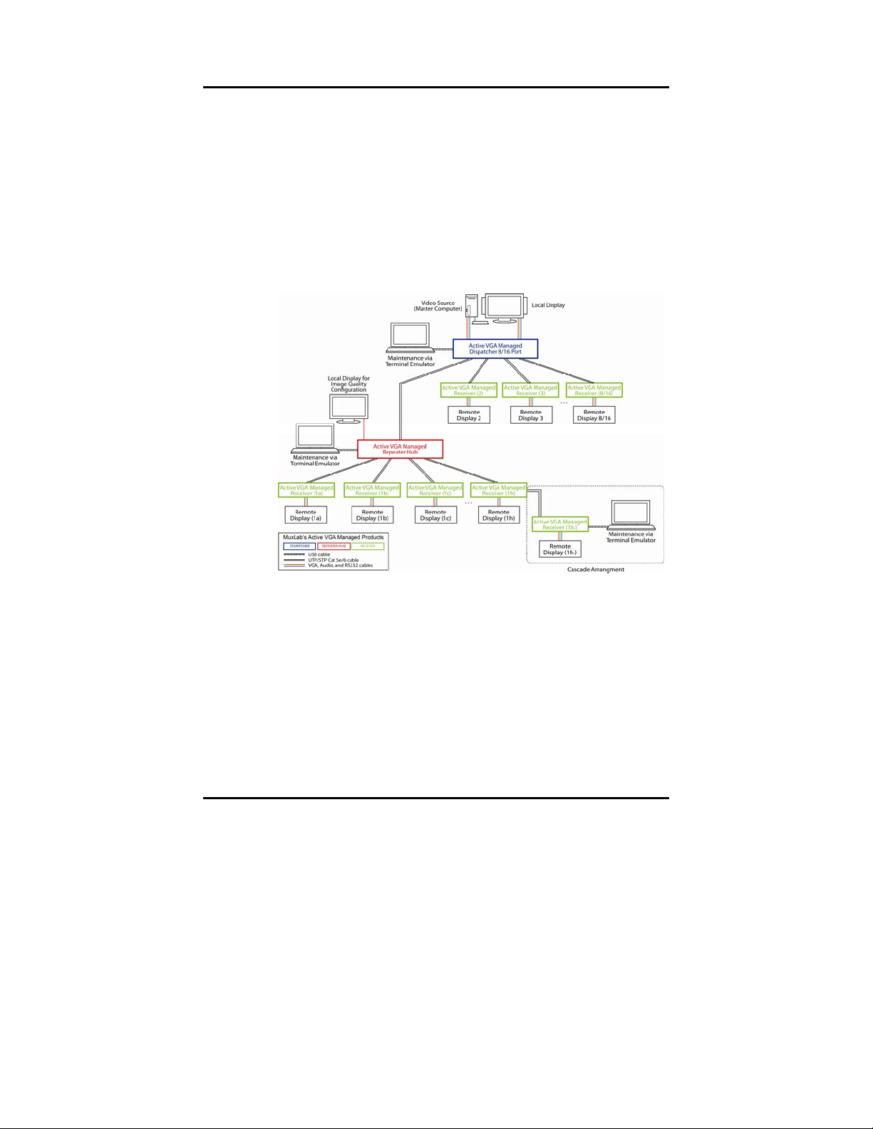
A video source is connected to the Dispatcher, which in
turn distributes the source signal to Receivers placed in
locations as far as 1,000 feet (305 meters) away. Each
Receiver then transmits this signal to as many as two
display devices. Working alone, the Dispatcher (8 or 16
port) can distribute signals to as many as 8 or 16 remote
locations.
A Repeater Hub is used whenever a source signal must
be distributed to more than 8 or 16 remote locations, or
over a distance of more than 1,000 feet. The Repeater
Hub receives the source signal from the Dispatcher,
amplifies and equalizes it, and then distributes it to as
many as 8 Receivers located as far as 1,000 feet away.
e 4
Page 5
© MuxLab Inc. Active VGA Managed Dispatcher Installation Guide
Pag
Because the Repeater Hub itself can be located as far as
1,000 feet away from the Dispatcher, the effective
distance from Dispatcher to Receiver is therefore
doubled to 2,000 feet (610 meters). Furthermore, since
the Dispatcher (8 or 16 port) can distribute signals to as
many as 8 or 16 Repeater Hubs, each of which in turn
can distribute signals to 8 Receivers, the number of
remote locations that receive source signals increases by
7 with each Repeater Hub used.
Figure 1: System Overview
The Dispatcher supports up to 1920 x 1200 pixels and
1080p resolution, and is DDC compliant with all plugand-play laptops, PCs, and displays.
Applications include commercial and residential AV
systems, classroom projector systems, digital signage,
boardroom systems, multi-room systems, classroom
training, retail systems, collaborative PC systems, and
medical information systems.
e 5
Page 6

© MuxLab Inc. Active VGA Managed Dispatcher Installation Guide
Page 6
1.2. System Features
Supports VGA, Audio & RS232
Support up to 1,000 ft (305 m)
Support up to 1920 x 1200, 1080p (depending on
cable length)
Software and manual adjustments for brightness,
sharpness & skew
Additional 1,000 ft (305 m) via Repeater Hub
Cascadability option from Receiver
Structured cabling approach: Repeater Hubs have
RJ45 for signal distribution
Dual head capability on Receiver
Page 7
© MuxLab Inc. Active VGA Managed Dispatcher Installation Guide
Pag
n
2.
Technical Specifications
Active VGA Managed DISPATCHER
Environment
Devices
Transmission
Maximum resolution
Connections
Maximum Distance:
Dispatcher to Receiver
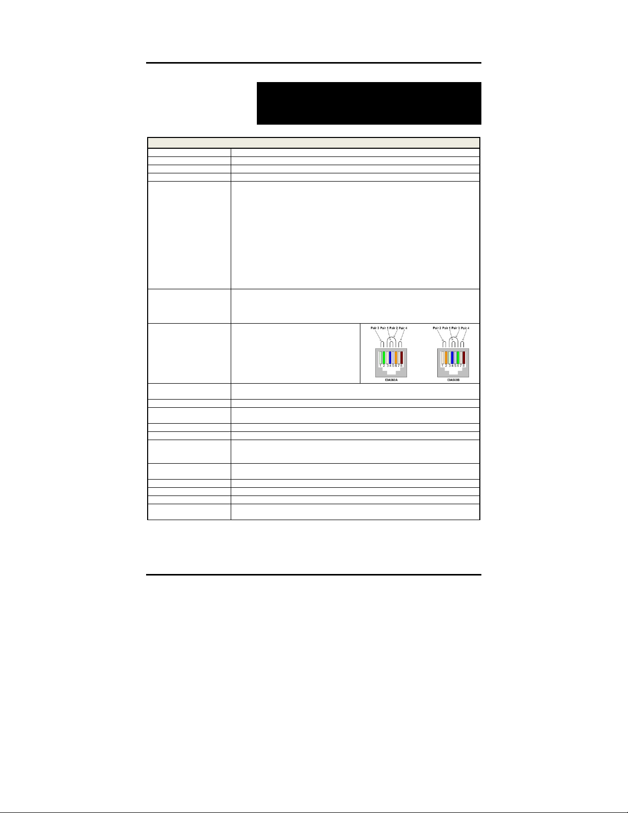
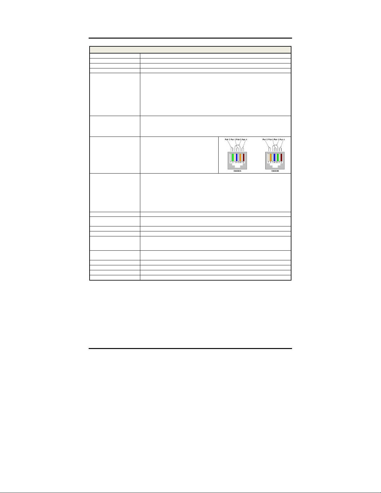
RJ45 Pin Configuration
Reverse Polarity Sensitive
Use EIA/TIA 568A or 568B
straight-through wiring
LED Indicators
Cable
Power Supply
Compatible Products
Power Consumption
Temperature
Dimensions
Weight
Regulatory
Warranty
Order Information
VGA, Analog Stereo Audio, RS232
PC, laptops, projectors, plasma, switchers, distribution amps, touchscreen
Transparent to the user
1080p; 1920 x 1200
FRONT PANEL Maintenance: One (1) Mini USB
Link Ports: Eight (8) or Sixteen (16) RJ45S
BACK PANEL Local In:
RS232 In: One (1) DB9F
Audio In: One (1) 3.5 mm stereo jack
VGA In: One (1) HD15F
Local Out:
RS232 Out: One (1) DB9M
Audio Out: One (1) 3.5 mm stereo jack
VGA Out: One (1) HD15F
Power: One (1) power jack
Up to 1920 x 1200 @ 60Hz; 1080P (depending on cable length)
Up to 1,000 feet (305 meters)
NOTE: STP cables must be used in an electrically noisy environment. Also, cross-connectio
reduces the effective distance depending on the grade of twisted cable used.
Green: Pin 4 (R) Pin 5 (T)
Blue: Pin 1 (R) Pin 2 (T)
Red: Pin 7 (R) Pin 8 (T)
COM: Pin 3 (R) Pin 6 (T)
Sync: One (1) green LED
Power
: One (1) green LED
Cat 5e/6 unshielded twisted pair (or better)
110-240V/12VDC/1.25A power jacks
Removable AC blades included for North America, Continental Europe & UK
500172, 500174
8 Watts
Operating: 0ºC to 40ºC
Storage: -20ºC to 85ºC
Humidity: Up to 95% non-condensing
1U Rack Mountable
Enclosure Dimensions: 17.15” x 4.69” x 1.72” (43.56 cm x 11.91 cm x 4.37 cm)
4.8 lb (2.2 kg)
FCC, CE-EMC Directive 89/336/EE, RoHS, WEEE
Two (2) years
500170: Active VGA Managed Dispatcher 8 Ports
500171: Active VGA Managed Dispatcher 16 Ports
e 7
Page 8
© MuxLab Inc. Active VGA Managed Dispatcher Installation Guide
Pag
n
Environment
Devices
Transmission
Maximum resolution
Connections
Maximum Distance:
Dispatcher to Receiver,
Repeater Hub to Receiver
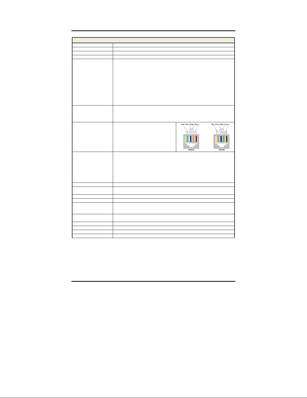
RJ45 Pin Configuration
Reverse Polarity Sensitive
Use EIA/TIA 568A or 568B
straight-through wiring
LED Indicators
Cable
Power Supply
Compatible Products
Power Consumption
Temperature
Dimensions
Weight
Regulatory
Warranty
Order Information
VGA, Analog Stereo Audio, RS232
PC, laptops, projectors, plasma, switchers, distribution amps, touchscreen
Transparent to the user
1080p; 1920 x 1200
FRONT PANEL VGA 2 Out: One (1) HD15F
Audio 2 Out: One (1) 3.5 mm stereo jack
RS232 2 Out: One (1) DB9M
Maintenance: One (1) Mini USB
BACK PANEL Power: One (1) power jack
Link In: One (1) RJ45S
VGA 1 Out: One (1) HD15F
Audio 1 Out: One (1) 3.5 mm stereo jack
RS232 1 Out: One (1) DB9M
Cascade Out: One (1) RJ45S
Up to 1920 x 1200 @ 60Hz; 1080P (depending on cable length)
Up to 1,000 feet (305 meters)
NOTE: STP cables must be used in an electrically noisy environment. Also, cross-connectio
Cat 5e/6 unshielded twisted pair (or better)
110-240V/12VDC/0.5A power jacks
Removable AC blades included for North America, Continental Europe & UK
500170, 500171, 500172
6 Watts
Operating: 0ºC to 40ºC
Storage: -20ºC to 85ºC
Humidity: Up to 95% non-condensing
Hybrid VESA 75 mm and 100 mm Mounting Surface
Enclosure Dimensions: 5.68” x 4.45” x 1.04” (14.42 cm x 11.30 cm x 2.64 cm)
2.0 lb (0.9 kg)
FCC, CE-EMC Directive 89/336/EE, RoHS, WEEE
Two (2) years
500174: Active VGA Managed Receiver (Dual Head)
Active VGA Managed RECEIVER
reduces the effective distance depending on the grade of twisted cable used.
Green: Pin 4 (R) Pin 5 (T)
Blue: Pin 1 (R) Pin 2 (T)
Red: Pin 7 (R) Pin 8 (T)
COM: Pin 3 (R) Pin 6 (T)
Sync
: One (1) green LED
Power: One (1) green LED
Sharpness One (1) green LED
Gain One (1) green LED
R One (1) green LED
G One (1) green LED
B One (1) green LED
e 8
Page 9
© MuxLab Inc. Active VGA Managed Dispatcher Installation Guide
Pag
n
Active VGA Managed REPEATER HUB
Environment
Devices
Transmission
Maximum resolution
Connections
Maximum Distance:
Repeater Hub to Receiver
RJ45 Pin Configuration
Reverse Polarity Sensitive
Use EIA/TIA 568A or 568B
straight-through wiring
LED Indicators
Cable
Power Supply
Compatible Products
Power Consumption
Temperature
Dimensions
Weight
Regulatory
Warranty
Order Information
VGA, Analog Stereo Audio, RS232
PC, laptops, projectors, plasma, switchers, distribution amps, touchscreen
Transparent to the user
1080p; 1920 x 1200
FRONT PANEL Maintenance: One (1) Mini USB
Link Ports: Eight (8) RJ45S
BACK PANEL Local Out:
VGA: One (1) HD15F
Local In:
Link: One (1) RJ45S
Power: One (1) power jack
Up to 1920 x 1200 @ 60Hz; 1080P (depending on cable length)
Up to 1,000 feet (305 meters)
NOTE: STP cables must be used in an electrically noisy environment. Also, cross-connectio
reduces the effective distance depending on the grade of twisted cable used.
Green: Pin 4 (R) Pin 5 (T)
Blue: Pin 1 (R) Pin 2 (T)
Red: Pin 7 (R) Pin 8 (T)
COM: Pin 3 (R) Pin 6 (T)
Sync
: One (1) green LED
Power: One (1) green LED
Sharpness One (1) green LED
Gain One (1) green LED
R One (1) green LED
G One (1) green LED
B One (1) green LED
Cat 5e/6 unshielded twisted pair (or better)
110-240V/12VDC/1.25A power jacks
Removable AC blades included for North America, Continental Europe & UK
500170, 500171, 500174
15 Watts
Operating: 0ºC to 40ºC
Storage: -20ºC to 85ºC
Humidity: Up to 95% non-condensing
1U Rack Mountable
Enclosure Dimensions: 17.15” x 4.69” x 1.72” (43.56 cm x 11.91 cm x 4.37 cm)
3.8 lb (1.7 kg)
FCC, CE-EMC Directive 89/336/EE, RoHS, WEEE
Two (2) years
500172: Active VGA Managed Repeater Hub (8 Port)
e 9
Page 10

© MuxLab Inc. Active VGA Managed Dispatcher Installation Guide
Pag
3.
Installation Procedure
3.1. Parts List
The Active VGA Managed Dispatcher 8/16 Port
(500170/500171) comes with the following parts:
Base Unit
One (1) 110-240V/12VDC, 1.25A Power Supply with
three interchangeable blades
One (1) RS232 DB9 to DB9 cable
One (1) VGA DB15 to DB15 cable
One (1) Audio cable
Quick Reference Support Sheet
Four (4) rubber feet
Please verify that all parts are present before proceeding.
e 10
Page 11

© MuxLab Inc. Active VGA Managed Dispatcher Installation Guide
Pag
3.2. Product Overview
The external connections and connection indicators of
the Active VGA Managed Dispatcher are detailed in
Figures 2 and 3. Please familiarize yourself with them
before installing the unit.
Figure 2: Front Panel of Dispatcher
Detail A
A1 = Status LEDs
= Maintenance Port (Mini USB)
A
2
A
= Push Button
3
Detail B
RJ45 Output Link Ports
e 11
Page 12

© MuxLab Inc. Active VGA Managed Dispatcher Installation Guide
Pag
Figure 3: Back Panel of Dispatcher
Detail A
A1 = RS232 Local Out
A
= Audio Local Out
2
= VGA Local Out
A
3
= RS232 Local In
A
4
= Audio Local In
A
5
A
= VGA Local In
6
A7 = Power Supply Port
e 12
Page 13

© MuxLab Inc. Active VGA Managed Dispatcher Installation Guide
Pag
3.3. Pre-Installation Checklist
The Active VGA Managed Dispatcher provides a
centralized VGA dispatching center by means of copper
UTP/STP cables.
1. The Dispatcher is connected to the VGA video
source, usually a PC or Laptop computer, via video,
audio cables and RS232 cables (included).
2. The Dispatcher is typically installed in a remote
telecom room and is connected to remote display
devices via Cat 5e/6 UTP/STP cables. Each remote
display device is connected to one MuxLab Active
VGA Managed Dual Head Receiver, which in turn is
connected to the Dispatcher via Cat 5e/6 cables. A
MuxLab Active VGA Managed Repeater Hub may
also be used in conjunction with the Dispatcher to
increase the distance between the VGA source and
remote display devices.
3. The maximum cable distance between the
Dispatcher and any given Receiver may be up to
1,000 feet. This distance may effectively be doubled
by connecting MuxLab’s Active VGA Managed
Repeater Hub between the Dispatcher and Receivers.
When cascading Receivers (see MuxLab’s Active
VGA Managed Receiver Installation Guide), the
combined cable length of all segments comprising
the cascade cannot exceed a maximum distance of
1,000 feet.
e 13
Page 14

© MuxLab Inc. Active VGA Managed Dispatcher Installation Guide
Pag
3.4. Physical Installation
MuxLab’s Active VGA Managed Dispatcher comes
with mounting brackets for standard 19” rack mounting.
Select the final destination for the product and install the
unit using standard rack-mount screws.
For set-top installation, the L-brackets on the side of the
unit may be removed and the included rubber feet placed
on the bottom of the unit. When removing the Lbrackets, be careful to keep and reinstall the four screws
on each side of the unit.
Figure 4: Procedure for Set-Top Installation
e 14
Page 15

© MuxLab Inc. Active VGA Managed Dispatcher Installation Guide
Pag
3.5. Installation Procedure
In order to install the product, please follow the steps
below:
1. Place the Active VGA Managed Dispatcher in its
final location.
2. Connect the source to the Dispatcher via the RS232,
Audio, VGA ports located on the back panel (Local
In). Ensure that the power is turned OFF at the
source. NOTE: Do not connect the power supply to
the Dispatcher at this point.
3. Optional: Connect a local display to the Dispatcher
via the RS232, Audio, VGA ports located on the
back panel (Local Out).
4. In order to distribute the VGA source to remote
displays, each remote display must be connected to
one (1) Active Managed Receiver (500174). To
install a Receiver, please refer to MuxLab’s Active
VGA Managed Receiver Installation Guide.
5. Complete the connection between the Dispatcher
and each remote display using standard straight-thru
Cat 5e/6 UTP/STP cables and connecting hardware,
terminated on RJ45 plugs at both ends. Ensure that
there are no split pairs or taps.
6. Optional: MuxLab’s Active VGA Managed Repeater
Hub (500172) may be connected to the Dispatcher to
increase the distance of remote displays by up to an
additional 1,000 ft (305 m). For installing a Repeater
e 15
Page 16

© MuxLab Inc. Active VGA Managed Dispatcher Installation Guide
Pag
Hub, please refer to MuxLab’s Active VGA Managed
Repeater Hub Installation Guide.
7. Power up the Receivers and local displays.
8. Connect the external 12VDC power supply to the
Dispatcher and plug the power supply into an AC
power outlet. If power is available, the power LED
will be ON.
9. Ensure that the source and appropriate displays are
on. Images should appear on the displays. Check the
image quality and refer to the troubleshooting table
in Section 4 if image quality is unsatisfactory.
10. Figures 5 and 6 show some typical configurations:
Figure 5: Simple Dispatcher/Receiver Configuration
e 16
Page 17

© MuxLab Inc. Active VGA Managed Dispatcher Installation Guide
Pag
Figure 6: Dispatcher/Receiver & Repeater Hub Configuration
e 17
Page 18

© MuxLab Inc. Active VGA Managed Dispatcher Installation Guide
Pag
3.6. Port Control Operations
MuxLab’s Active VGA Managed Dispatcher may be
controlled in any one of two different ways:
1. RS232 Control
2. USB Control
1. RS232 Control
The Active VGA Managed Dispatcher features built-in
firmware that allows commands from the computer unit
running MuxLab’s Control Central software to be sent
directly to the Dispatcher via an RS232 connection. If
connecting with an RS232 cable, ensure that the cable
has the straight-through configuration shown in Figure
6.
2
3
5
DB9
Male
Figure 7: RS232 Cable Configuration
2
3
5
DB9
Female
Port Control is performed with MuxLab’s Active VGA
Managed Software, described in the Active VGA
Managed Software Installation Guide.
Please note that USB to RS232 converter cables could
result in problems, depending on the quality of the
converters.
e 18
Page 19

© MuxLab Inc. Active VGA Managed Dispatcher Installation Guide
Pag
2. USB Control
The Active VGA Managed Dispatcher features built-in
firmware that allows commands from an ASCII terminal
to be sent directly to the Dispatcher via a USB
connection only for maintenance purposes.
Maintenance is performed with a terminal emulator,
such as the one available under Windows with the
ASCII Command Set described in the Appendix.
e 19
Page 20

© MuxLab Inc. Active VGA Managed Dispatcher Installation Guide
Pag
3.7. Driver Setup
When interfacing a MuxLab device with Windows 2000
(or more recent) operating system, a driver setup file
will be required.
To install the MuxLab Control Center software, go to
www.muxlab.com and download the SC-000032-A
USB to Serial Driver. Plug the USB cable between the
device and the PC, and power up the device. The Found
New Hardware wizard will open (Figure 8). Select
Locate and install driver software.
Figure 8: Found New Hardware Wizard
e 20
Page 21

© MuxLab Inc. Active VGA Managed Dispatcher Installation Guide
Pag
A new dialog box will open (Figure 9). Select Browse
my computer for driver software.
Figure 9: Found New Hardware Dialog Box
Another dialog box will open (Figure 10). Click Browse
and locate the SC-000032-A file that you downloaded.
Once found, click Next.
Figure 10: Browsing for Unknown Device
e 21
Page 22

© MuxLab Inc. Active VGA Managed Dispatcher Installation Guide
Pag
A security window will now appear, indicating that the
driver software is unsigned (Figure 11). Select Install
this driver software anyway.
Figure 11: Windows Security
A window will appear instructing that the software for
the driver has been successfully installed (Figure 12).
Click Close. You are now ready to launch the MuxLab
Control Center software.
Figure 12: Successful Installation Dialog Box
e 22
Page 23

© MuxLab Inc. Active VGA Managed Dispatcher Installation Guide
Pag
4.
Troubleshooting
The following table describes some of the problem symptoms, the
probable causes and possible solutions. If the information below
does not solve the problem, the technical support contact
information can be found at the end of this section.
Problem Possible Solutions
No Image • Check that the Power LED is ON. (If not, check the power supply.)
No Image • Check that the Sync LED of the Dispatcher is ON.
No Image • Check that the Sync LED of the Receivers is ON. (Otherwise, check UTP/STP cables.)
No Image • Check that the source is plugged into the Dispatcher’s input, not into the local monitor out.
No Image • Check that the Receivers are powered up and that the Power LED is ON.
Choppy Sound • Check cable lengths.
Smeared Picture • Check cable lengths.
Not All Display
Devices Work
• Check that the source PC is ON.
• Check that the local monitor is ON.
• Power down, and then power up the Dispatcher.
• Check that the power supplies are not mixed up
(Dispatcher & Repeater Hub require 1.25A power supply. Receiver requires 0.5A power supply).
• Use STP cables if equipment is located in electrically noisy environment.
• When cascading multiple Receivers, ensure that the combined cable length of all segments
comprising the cascade does not exceed 1,000 feet (305 meters).
• Adjust Sharp and Gain controls.
• When cascading multiple Receivers, ensure that the combined cable length of all segments
comprising the cascade does not exceed 1,000 feet (305 meters).
• Check cable lengths.
• Check that video source is outputting a signal that is compatible with all the display devices
(try 480p or 720p).
e 23
Page 24

© MuxLab Inc. Active VGA Managed Dispatcher Installation Guide
Pag
When contacting your nearest MuxLab dealer or MuxLab
Technical Support at 877-689-5228 (toll free in North America) or
(+1) 514-905-0588 (International), please have the following
information ready:
Unit model number.
Cabling layout. Please include the model of the video card
and display monitor(s), as well as cable types and lengths.
Description of problem .
List of tests performed.
e 24
Page 25

© MuxLab Inc. Active VGA Managed Dispatcher Installation Guide
Pag
5.
Appendix
[Awaiting Input from Kefil]
e 25
Page 26

© MuxLab Inc. Active VGA Managed Dispatcher Installation Guide
Pag
6.
Product Warranty Policy
Items Under Warranty – Company Policy
MuxLab guarantees its products to be free of defects in manufacturing and workmanship for the
warranty period from the date of purchase. If this product fails to give satisfactory performance
during this warranty period, MuxLab will either repair or replace this product at no additional
charge, except as set forth below. Repair and replacement parts will be furnished on an exchange
basis and will be either reconditioned or new. All replaced parts and products become the property
of MuxLab. This limited warranty does not include repair services for damage to the product
resulting from accident, disaster, misuse, abuse, or unauthorized modifications or normal decay of
battery driven devices. Batteries, if included with the product, are not covered under this warranty.
Limited warranty service can be obtained by delivering the product during the warranty period to the
authorized MuxLab dealer from whom you purchased the product, or by sending it to MuxLab.
MuxLab will not accept any such product for repair without a Return Material Authorization (RMA)
number issued by its Customer Service Department and a proof of purchase date. If this product is
delivered to MuxLab by mail, you agree to assume risk of loss or damage in transit, to prepay
shipping charges to the warranty service location, and to use the original shipping container or
equivalent.
THE ABOVE LIMITED WARRANTY IS THE ONLY WARRANTY COVERING YOUR
MUXLAB PRODUCT. THERE ARE NO OTHER WARRANTIES, EXPRESSED OR IMPLIED,
INCLUDING WARRANTIES OF MERCHANTABILITY OR FITNESS FOR A PARTICULAR
PURPOSE. SOME STATES DO NOT ALLOW LIMITATIONS ON IMPLIED WARRANTIES,
SO THE ABOVE LIMITATION MAY NOT APPLY TO YOU.
IF THIS PRODUCT IS NOT IN GOOD WORKING ORDER, YOUR S OLE RE ME DY SHALL BE
REPAIR OR REPLACEMENT AS PROVIDED FOR ABOVE. IN NO EVENT SHA LL MUXLAB
BE LIABLE TO YOU FOR ANY DAMAGES, INCLUDING ANY L OSS OF PROFITS, LOST
SAVINGS, OR OTHER INCIDENTAL OR CONSEQUENTIAL DAMAGES ARISING OUT O F
THE USE OF OR INABILITY TO USE THIS PRODUCT, EVEN IF MUXLAB OR AN
AUTHORIZED MUXLAB DEALER HAS BEEN ADVISED OF T HE POSSIBILITY OF SUCH
DAMAGES; NOR WILL MUXLAB BE LIABLE FOR ANY CLAIM BY ANY OTHER PARTY.
SOME STATES DO NOT ALLOW THE EXCLUS ION OR LIMITATION OF INCIDENTAL OR
CONSEQUENTIAL DAMAGES FOR CONSUMER PRODUCTS, SO THE ABOVE
LIMITATIONS OR EXCLUSIONS MAY NOT APPLY TO YOU . THIS WARRANTY GIVES
YOU SPECIFIC LEGAL RIGHTS. YOU MAY ALSO HAVE OTHER RIGHTS WHICH MAY
VARY FROM STATE TO STATE.
e 26
Page 27

© MuxLab Inc. Active VGA Managed Dispatcher Installation Guide
Pag
Warranty Periods
Any product found to be defective within three (3) months of invoice, including one (1) month shelf
life, may be returned for replacement by a new unit or a satisfactory repair within one (1) month of
having been received by MuxLab. The customer must provide MuxLab with the serial number and
proof of purchase of the defective unit being returned. All RMAs issued are subject to inspection by
MuxLab, and will be returned to the customer if not properly packaged – units must be returned in
their original container or equivalent. MuxLab will not accept any such product for repair without
an authorization for its Technical Support department and without an RMA number issued by
MuxLab’s Customer Service department. For credit and replacement RMAs, the customer will be
liable to pay the replacement invoice if defective products are not returned.
Products More than Six Months Old, Including Shelf Life
The defective unit must be returned prepaid to MuxLab, and the unit will be repaired. If repairing the
unit is not possible, it will be replaced by an equivalent unit and returned to the customer within one
(1) month of having been received by MuxLab. There is no charge for repair (parts and labor) during
the full warranty period.
Products Defective and Not Under Warranty
MuxLab’s policy is to repair and return any defective MuxLab products that are no longer under
warranty. An amount of 25% of the unit’s published list price at the time of purchase will be
charged. The customer must issue a purchase order in order to cover repair costs.
Each unit will be returned to the customer within one (1) month of having been received by MuxLab.
The defective unit must be returned prepaid to MuxLab. The repaired unit will be returned to the
customer FOB MuxLab. The repaired unit has a 90-day warranty.
e 27
Page 28

© MuxLab Inc. Active VGA Managed Dispatcher Installation Guide
Pag
MuxLab Inc.
8495 Dalton Road
Mount Royal, Quebec
Canada H4T 1V5
Tel.: +1 (514) 905-0588 Fax: +1 (514) 905-0589
Toll Free (North America): 877 689-5228
URL: www.muxlab.com
E-mail: videoease@muxlab.com
e 28
 Loading...