

Page 1
VideoEase™
Active VGA Balun II Family
500140: Active VGA Balun II Kit (Tx & Rx)
500142: Active VGA Balun II, Rx, no PSU
500144: Power Supply for 500142
Installation Guide
P/N: 94-000622-B SE-000604-B
Page 2

© MuxLab Inc. Active VGA Balun II Family Installation Guide
Pag
Copyright Notice :
Copyright © 2008 MuxLab Inc. All rights reserved.
Printed in Canada. No part of this publication may be reproduced,
stored in a retrieval system, or transmitted in any form or by any
means, electronic, mechanical, photocopying, recording, or
otherwise without prior written permission of the author.
Trademarks :
MuxLab and VideoEase are registered trademarks of MuxLab Inc.
e 2
Page 3

© MuxLab Inc. Active VGA Balun II Family Installation Guide
Pag
Table of Contents
1. Overview ........................................................................4
1.1. Description........................................................4
1.2. Features.............................................................5
2. Technical Specifications ...............................................6
3. Installation Procedure ..................................................7
3.1. Parts List ...........................................................7
3.2. Product Overview .............................................8
3.3. Pre-Installation Checklist .................................9
3.4. Installation Procedure .....................................10
3.5 Cascadability………………………………..14
4. Troubleshooting ..........................................................15
5. Product Warranty Policy ...........................................17
e 3
Page 4

© MuxLab Inc. Active VGA Balun II Family Installation Guide
Pag
1.
Overview
1.1. Description
The Active VGA/Component Balun II Kit allows VGA
or component video to be transmitted via cost-efficient
unshielded copper twisted cable in a point-to-point
configuration.
The product supports remote power pass-thru and is
DDC compliant with all “plug-and-play” laptops, PCs
and displays. The product supports up to 1920 x 1200
pixels and 1080p resolution and features manual gain
adjustment and local monitor output for added
versatility.
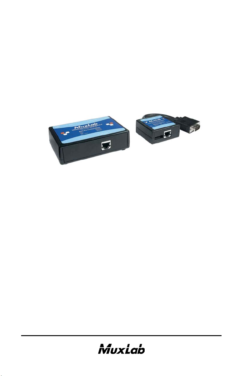
The product converts the VGA signal from an
unbalanced signal to a balanced signal and amplifies and
equalizes the signal at the receiving end. It provides
excellent image quality and minimizes distortions due to
smearing, propagation delay and phase deviation. The
transmitter and receiver are shown in the photo below.
Applications include; Digital signage, residential,
boardroom, classroom, and medical imaging video
systems.
e 4
Page 5

© MuxLab Inc. Active VGA Balun II Family Installation Guide
Pag
1.2. Features
• Up to 600 ft (180m) via Cat5E/6 @ 1920 x 1200
• Up to 600 ft (180m) via Cat5E/6 @ 1080p
• Remote power pass-thru up to 150 ft (46m)
• DDC1/DDC2 (Plug-and-Play) Compliant
• Manual gain compensation
• Local monitor output
• Up to four (4) transmitters may be cascaded
e 5
Page 6
© MuxLab Inc. Active VGA Balun II Family Installation Guide
Pag
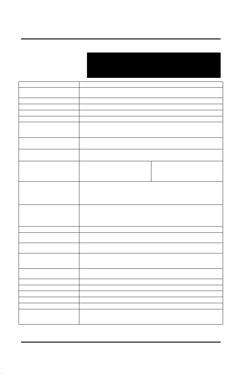
2.
Technical Specifications
Environment
Devices
Transmission
Bandwidth
Input Impedance
Output Impedance Connectors –
Transmitter
Connectors –
Receiver
Maximum Distance –
Remote Power
Max. Distance –
VGA via Cat 5 (or
better) Twisted Pair
Max Distance –
Component Video
(YPbPr) via Cat 5 (or
better) Twisted Pair
RJ45 Pin Configuration
Reverse Polarity Sensitive
Use EIA/TIA 568 A or B,
straight-through wiring
Gain Adjustment
LED Indicators
Cable
Power Supplies
Temperature
Enclosure
Dimensions
Weight
Regulatory
Warranty
Order Information
VGA. VESA VP&D 1.0, VIP ver 2.0. DDC1 and DDC1.
PCs, laptops, CRT monitors, LCD monitors, plasma screens, DLP
projectors.
Transparent to the user.
Up to 220 MHz (1920 x 1200 resolution), 1080p
HD15; 75 ohms
Cat5: 100 ohms
VGA/Component Input (PC): DB15HD-F
VGA/Component Output (Local Monitor): DB15HD-F
VGA/Component Output (Cat5): RJ45 shielded
VGA/Component Input (Cat5): RJ45 shielded
VGA/Component Output (Display): DB15HD-M
150 ft (46m) (Tx Balun unpowered, Rx balun powered)
150 ft (46m) (Tx Balun powered, Rx balun unpowered)
640 x 480 (VGA): 1000 ft (305m)
800 x 600 (SVGA): 1000 ft (305m)
1024 x 768 (XGA): 1000 ft (305m)
1280 x 1024 (SXGA): 850 ft (260m)
480i/p: 1,000 ft (305 m)
1080i: 850 ft (260 m)
1080p: 600 ft (180 m)
* VGA-to-component video cables required (not included)
Red: Pin 7 (R) Pin 8 (T)
Green: Pin 3 (R) Pin 6 (T)
Blue: Pin 1 (R) Pin 2 (T)
DDC/Remote Power: Pin 4 (R) Pin 5 (T)
Gain control via DIP switches on receiver (factory default setting: all OFF)
Tx Balun: Power: One (1) green LED Sync: One (1) green LED
Rx Balun: Power: One (1) green LED
Category 5 or better twisted pair cable.
Transmitter requires additional VGA jumper cables (not included)
110-240V/12VDC/0.5. Removable AC blades included for North
America and Continental Europe.
12VDC power jacks.
Operating: 0º to 40º C. Storage:-10º to 70º C.
Humidity: up to 95% non-condensing.
Black. ABS fire retardant plastic
4.5” x 3.8” x 1.25” (11.4 cm x 9.7 cm x 3.2cm)
2 lbs, .9 Kg
FCC/CE, RoHS
Two (2) years
500140: Active VGA Balun II Kit
500142: Active VGA Balun II, Receiver Only (Display), No PSU
500144: Power Supply 100-240V/12VDC/.5A for 500142
1600 x 1200 (UXGA): 800 ft (245m)
1366 x 768 (WXGA): 850 ft (260m)
1680x1050 (WSXGA): 850 ft (260m)
1920 x 1200 (WUXGA):600 ft (180m)
e 6
Page 7

© MuxLab Inc. Active VGA Balun II Family Installation Guide
Pag
3.
Installation Procedure
3.1. Parts List
The Active VGA Balun II Kit (500140) comes with the
following parts. Please verify that all pieces are present
before proceeding.
• Transmitter
• Receiver
• Two (2) External Power Supplies (12 VDC, 0.5A)
• Blades for North America, Continental Europe and
UK
• Installation Guide
The Active VGA Balun Receiver (500142) and Power
Supply (500144) are also sold separately for use with
the VGA Hub (500150).
VGA jumper cables and Category 5e/6 cable are not
included.
e 7
Page 8

© MuxLab Inc. Active VGA Balun II Family Installation Guide
Pag
3.2. Product Overview
The external connections and diagnostic indicators of
the Active VGA Balun II are detailed in the following
diagrams. Please familiarize yourself with them before
installing the components.
Figure 1: Transmitter
Figure 2: Receiver
e 8
Page 9

© MuxLab Inc. Active VGA Balun II Family Installation Guide
Pag
3.3. Pre-Installation Checklist
There are two (2) components: the transmitter and the
receiver.
1. The transmitter is connected to the video source,
usually a PC, by a VGA jumper cable (not included).
2. A local monitor can be connected to the transmitter
by a VGA jumper cable (not included).
3. The transmitter is connected to the receiver by
Category 5e/6 (or higher) UTP cable (not included).
4. The receiver is connected to the display equipment,
usually a projector or screen, by a VGA jumper
cable (not included) or directly on the equipment.
5. Verify that the desired image resolution is within the
specification of the Active VGA Balun II Kit.
e 9
Page 10

© MuxLab Inc. Active VGA Balun II Family Installation Guide
Pag
3.4. Installation Procedure
Verify that the distance between the Active VGA
Balun II transmitter and receiver are within MuxLab
specifications (see Technical Specifications). In order to
install the transmitter, please follow the steps below:
1. Connect the transmitter to the video source with a
VGA jumper cable.
2. (Optional) Connect a local monitor to the transmitter
with a VGA jumper cable.
3. Connect a length of Category 5e/6 (or higher) UTP
cable to the transmitter. Ensure the wiring is
according to EIA 568 A or B. and straight-thru.
4. Connect the 12 VDC power supply first to the
transmitter and then plug the power supply into an
AC power outlet. If power is present, the green
power LED will be ON.
e 10
Page 11

© MuxLab Inc. Active VGA Balun II Family Installation Guide
Pag
To install the receiver, please follow the steps below:
5. Connect the Active VGA Balun II receiver to the
display equipment.
6. Connect the UTP cable to the Video IN/UTP
connector of the receiver.
7. If the distance exceeds MuxLab’s specified limit for
remote power, connect the second 12 VDC power
supply to the receiver and then plug the power
supply into an AC power outlet. If power is present,
then the green power LED will be ON.
8. To adjust the picture quality, toggle the gain
adjustment DIP switches on the rear panel of the
Active VGA Balun II receiver. The factory default
position is “all OFF” (up position).
O
N
1234
56
EQUAL GAIN
Figure 3: DIP switches for gain adjustment
e 11
Page 12

© MuxLab Inc. Active VGA Balun II Family Installation Guide
Pag
9. The following table provides suggested DIP switch
settings for Gain adjustments.
GAIN settings
(switches 4, 5 & 6)
000 -50%
001 -35%
010 -15%
011 0%
100 +15%
101 +35%
110 +45%
111 +50%
Actual gain or loss
Table 1: DIP switch settings for Gain adjustment
10. The following table provides suggested DIP switch
settings for equalization adjustments.
EQUAL
settings
(switches 1, 2 & 3)
Distance (ft)
(resolutions up to
1024x768)
Distance (ft)
(resolutions above
1024x768)
000 Up to 200ft Up to 200ft
001 200ft to 350ft 200ft to 350ft
010 350ft to 600ft 350ft to 500ft
011 600ft to 800ft 500ft to 650ft
100 800ft to 900ft 650ft to 750ft
101 900ft to 1000ft 750ft to 800ft
110 900ft to 1000ft 800ft to 900ft
111 1000ft + 900ft to 1000ft +
Table 2: DIP switch settings for Equalization adjustment
Note: For display equipment with automatic gain control (for example,
certain models of projectors), complete all installation procedures and
ensure that all DIP switches are OFF before turning the display
equipment on. Otherwise, the display could override the adjustable
gain feature of the VideoEase Active VGA Balun Kit.
e 12
Page 13

© MuxLab Inc. Active VGA Balun II Family Installation Guide
Pag
11. DIP switch positions 1 to 3 adjust the equalization to
compensate for high frequency signal loss due to the
Cat5E/6 cable.
12. The DIP switch positions 4 to 6 adjust the luminance
level to compensate for low frequency signal loss
due to the Cat5E/6 cable.
13. The following diagram shows the final
configuration.
Figure 4: Typical Configuration – Remote Power
14. Upon boot-up, the Active VGA Balun II reads the
DDC information from the Local Monitor (if
connected) and sets the monitor size and resolution
according to the Local Monitor.
15. If the Local Monitor is not connected, the Active
VGA Balun II reads the DDC information from the
remote screen and sets the size and resolution
according to the remote screen.
e 13
Page 14

© MuxLab Inc. Active VGA Balun II Family Installation Guide
Pag
3.5. Cascadability
In order to distribute one (1) VGA source to more than
one (1) display, up to four (4) transmitters may be
cascaded via the Local Monitor port as shown in the
following diagram.
e 14
Page 15

© MuxLab Inc. Active VGA Balun II Family Installation Guide
Pag
4.
Troubleshooting
The following table describes some of the problem symptoms, the
probable causes and possible solutions. If the information below
does not solve the problem, the technical support contact
information can be found at the end of this section.
Picture LED (TX)
Power Sync
No Image OFF OFF OFF No power Check power
No Image OFF OFF ON No power at
No Image ON --- OFF No power at
No Image ON OFF ON PC not present
No Image ON ON ON Cat 5 Cable Check continuity
Smearing ON ON ON Exceed cable
Ghosting ON ON ON Impedance
Wrong
colors
Loss of
detail
Image
shakes
ON ON ON Swapped pairs Check wiring
ON ON ON Exceed cable
ON ON ON Too much gain Reduce cable length
LED (RX)
Power
Probable
Cause
Transmitter
Receiver
or cable
problem
length
mismatch
length
Possible Solution
connections
Check power
connections. Check
distances for remote
powering
Check power
connections. Check
distances for remote
powering
Check VGA IN cable
Check correct wiring
Reduce cable length
Adjust Gain and
Equalization
Check cabling
Try different VGA
card or display
Reduce cable length
Adjust Equalization
Adjust Gain and
Equalization
e 15
Page 16

© MuxLab Inc. Active VGA Balun II Family Installation Guide
Pag
When contacting your nearest MuxLab dealer or MuxLab
Technical Support please have the following information ready:
• Unit model number.
• Cabling layout. Include model of PC and display used, cable
length and type.
• Description of problem.
• List of tests performed.
e 16
Page 17

© MuxLab Inc. Active VGA Balun II Family Installation Guide
Pag
5.
Product Warranty Policy
Items under warranty - Company Policy
MuxLab guarantees its products to be free of defects in manufacturing and workmanship for
the warranty period from the date of purchase. If this product fails to give satisfactory
performance during this warranty period, MuxLab will either repair or replace this product at
no additional charge, except as set forth below. Repair and replacement parts will be furnished
on an exchange basis and will be either reconditioned or new. All replaced parts and products
become the property of MuxLab. This limited warranty does not include repair services for
damage to the product resulting from accident, disaster, misuse, abuse, or unauthorized
modifications or normal decay of battery driven devices. Batteries if included with the product,
are not covered under this warranty.
Limited warranty service can be obtained by delivering the product during the warranty period
to the authorized MuxLab dealer from whom you purchased the product, or by sending it to
MuxLab. MuxLab will not accept any such product for repair without a Return Material
Authorization number (RMA#) issued by its Customer Service Department and a proof of
purchase date. If this product is delivered to MuxLab by mail, you agree to assume risk of loss
or damage in transit, to prepay shipping charges to the warranty service location, and to use the
original shipping container or equivalent.
THE ABOVE LIMITED WARRANTY IS THE ONLY WARRANTY COVERING YOUR
MUXLAB PRODUCT. THERE ARE NO OTHER WARRANTIES, EXPRESSED OR
IMPLIED, INCLUDING WARRANTIES OF MERCHANTABILITY OR FITNESS FOR A
PARTICULAR PURPOSE. SOME STATES DO NOT ALLOW LIMITATIONS ON
IMPLIED WARRANTIES, SO THE ABOVE LIMITATION MAY NOT APPLY TO YOU.
IF THIS PRODUCT IS NOT IN GOOD WORKING ORDER, YOUR SOLE REMEDY
SHALL BE REPAIR OR REPLACEMENT AS PROVIDED FOR ABOVE. IN NO EVENT
SHALL MuxLab BE LIABLE TO YOU FOR ANY DAMAGES, INCLUDING ANY LOSS
OF PROFITS, LOST SAVINGS, OR OTHER INCIDENTAL OR CONSEQUENTIAL
DAMAGES ARISING OUT OF THE USE OF OR INABILITY TO USE THIS PRODUCT,
EVEN IF MUXLAB OR AN AUTHORISED MuxLab DEALER HAS BEEN ADVISED OF
THE POSSIBILITY OF SUCH DAMAGES; NOR WILL MUXLAB BE LIABLE FOR ANY
CLAIM BY ANY OTHER PARTY. SOME STATES DO NOT ALLOW THE EXCLUSION
OR LIMITATION OF INCIDENTAL OR CONSEQUENTIAL DAMAGES FOR
CONSUMER PRODUCTS, SO THE ABOVE LIMITATIONS OR EXCLUSIONS MAY NOT
APPLY TO YOU. THIS WARRANTY GIVES YOU SPECIFIC LEGAL RIGHTS. YOU
MAY ALSO HAVE OTHER RIGHTS WHICH MAY VARY FROM STATE TO STATE.
e 17
Page 18

© MuxLab Inc. Active VGA Balun II Family Installation Guide
Pag
Warranty Periods
Any product found to be defective within three (3) months of invoice, including one (1) month
shelf life, may be returned for replacement by a new unit or a satisfactory repair within one (1)
month of receiving any returned product. The customer must provide MuxLab with the serial
number and proof of purchase of the defective unit being returned. All R.M.A.’s issued are
subject to inspection by MuxLab, and will be returned to customer if not properly package –
units must be returned in original container or equivalent. MuxLab will not accept any such
product for repair without an authorization for its Technical Support department and without a
return authorization number issued by MuxLab Customer Service department. For credit &
replace R.M.A., customer will be liable to pay replacement invoice if defective products are not
returned.
Product more than six months old, including shelf life.
The defective unit must be returned prepaid to MuxLab and then the unit will be repaired or if
repair is not possible, replaced by an equivalent unit and returned to the customer within one
(1) month of receiving any returned product. There is no charge for repair (parts and labor)
during the full warranty period.
Items Defective and not under Warranty
For products which are no longer under warranty the policy is repair and return. An amount
of 25% of the products published list price at the time of purchase will be charged. Customer
must issue a purchase order to cover the cost of repair.
Each unit will be returned to the customer within one (1) month from receipt of the unit by
MuxLab. The defective unit must be returned prepaid to MuxLab. The repaired unit will be
returned to the customer FOB MuxLab. The repaired unit has a 90 day warranty.
e 18
Page 19

© MuxLab Inc. Active VGA Balun II Family Installation Guide
Pag
e 19
Page 20

© MuxLab Inc. Active VGA Balun II Family Installation Guide
Pag
MuxLab Inc.
Tel.: (+1) 514 905-0588 Fax (+1) 514 905-0589
Toll Free (North America): 877 689-5228
URL: www.muxlab.com
E-mail: videoease@muxlab.com
e 20
 Loading...