

MuxLab 500811 Operation Manual
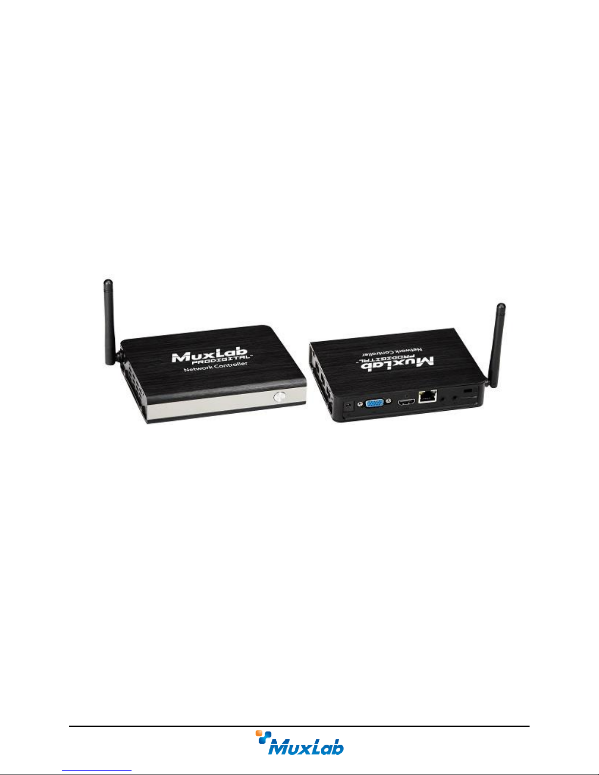
MuxLab Pro Digital Network Controller (MNC)
(Model: 500811)
Operation Manual
P/N: 94-000810-E SE-000810-E

© MuxLab Inc. ProDigital Network Controller (MNC)
Copyright Notice:
Copyright © 2014 MuxLab Inc. All rights reserved.
Printed in Canada. No part of this publication may be reproduced, stored in a retrieval system, or
transmitted in any form or by any means, electronic, mechanical, photocopying, recording or
otherwise without prior written permission of the author.
Trademarks:
MuxLab is a registered trademark of MuxLab Inc.
Page 2

© MuxLab Inc. ProDigital Network Controller (MNC)
Table of Contents
1. Overview .....................................................................................................................................5
1.1. Description ............................................................................................................................... 5
1.2. Features .................................................................................................................................... 6
2. Technical Specifications ............................................................................................................7
3. Installation and Use ...................................................................................................................8
3.1. Part List .................................................................................................................................... 8
3.2. Product Overview .................................................................................................................... 9
3.3. Installation Procedure ............................................................................................................ 10
3.4. Ethernet Web Interface – Device Management ..................................................................... 20
Extender Model 500752 ......................................................................................................... 22
Extender Model 500753 ......................................................................................................... 40
Extender Model 500754 ......................................................................................................... 59
Extender Model 500755 ......................................................................................................... 82
Extender Model 500756 ....................................................................................................... 101
Extender Model 500757 ....................................................................................................... 120
Extender Model 500758 ....................................................................................................... 136
Extender Model 500759 ....................................................................................................... 153
Extender Model 500755-AMP ............................................................................................. 174
Extender Model 500762 ....................................................................................................... 193
4. Troubleshooting .....................................................................................................................211
5. Appendix – IP Command API ..............................................................................................212
5.1 IP Command API: definition and format ...........................................................................212
5.1.1 Definition ............................................................................................................................. 212
5.1.2 General Format .................................................................................................................... 212
5.2 IP Command API for 500752\753\754\755\756: command/response list .........................213
5.2.1 Automatic discovery ............................................................................................................ 213
5.2.2 Manual discovery ................................................................................................................. 213
5.2.3 Get devices from the database.............................................................................................. 214
5.2.4 Update some devices attributes ............................................................................................ 214
5.2.5 Reboot device ....................................................................................................................... 216
5.2.6 Connect/disconnect device ................................................................................................... 216
5.2.7 Select and apply a preset ...................................................................................................... 217
5.2.8 Save current matrix connections in a specific preset ........................................................... 217
5.2.9 Save current matrix connections in a NEW preset name ..................................................... 218
Page 3

© MuxLab Inc. ProDigital Network Controller (MNC)
5.2.10 Delete a preset ...................................................................................................................... 218
5.2.11 Send data to RS-232 (For 500753/754/755/756/757/758/759) ............................................ 218
5.2.12 Send data to IR (For 500752/753/754 (TX) and 500755/756 (TX & RX) ........................... 219
5.2.13 Modify network setting OF THE MNC ............................................................................... 219
5.2.14 Modify Administrator password OF THE MNC ................................................................. 219
5.2.15 VIDEO WALL: Connection command (For 500754/759) .................................................. 220
5.2.16 VIDEO WALL: Select and apply a configuration (For 500754/500759) ............................ 221
5.2.17 VIDEO WALL: Changing source to a configuration (For 500754/500759) ....................... 221
5.3 IP Command API for 500480: command/response list ......................................................222
5.3.1 Get all port status from the database .................................................................................... 222
5.3.2 Get all presets ....................................................................................................................... 223
5.3.3 Connect/disconnect device ................................................................................................... 223
5.3.4 Update some ports attributes ................................................................................................ 223
5.3.5 Select and apply a preset ...................................................................................................... 224
5.4 Examples of commands .....................................................................................................224
6. Product Warranty Policy ......................................................................................................226
Page 4
© MuxLab Inc. ProDigital Network Controller (MNC)
1.
1.1.
TX
TX
TX
RX
RX
RX
Pro Digital
Network Controller
Smartphone
Overview
Description
The MuxLab Pro Digital Network Controller is a Linux-based PC that allows users to
control hub-installed MuxLab products.
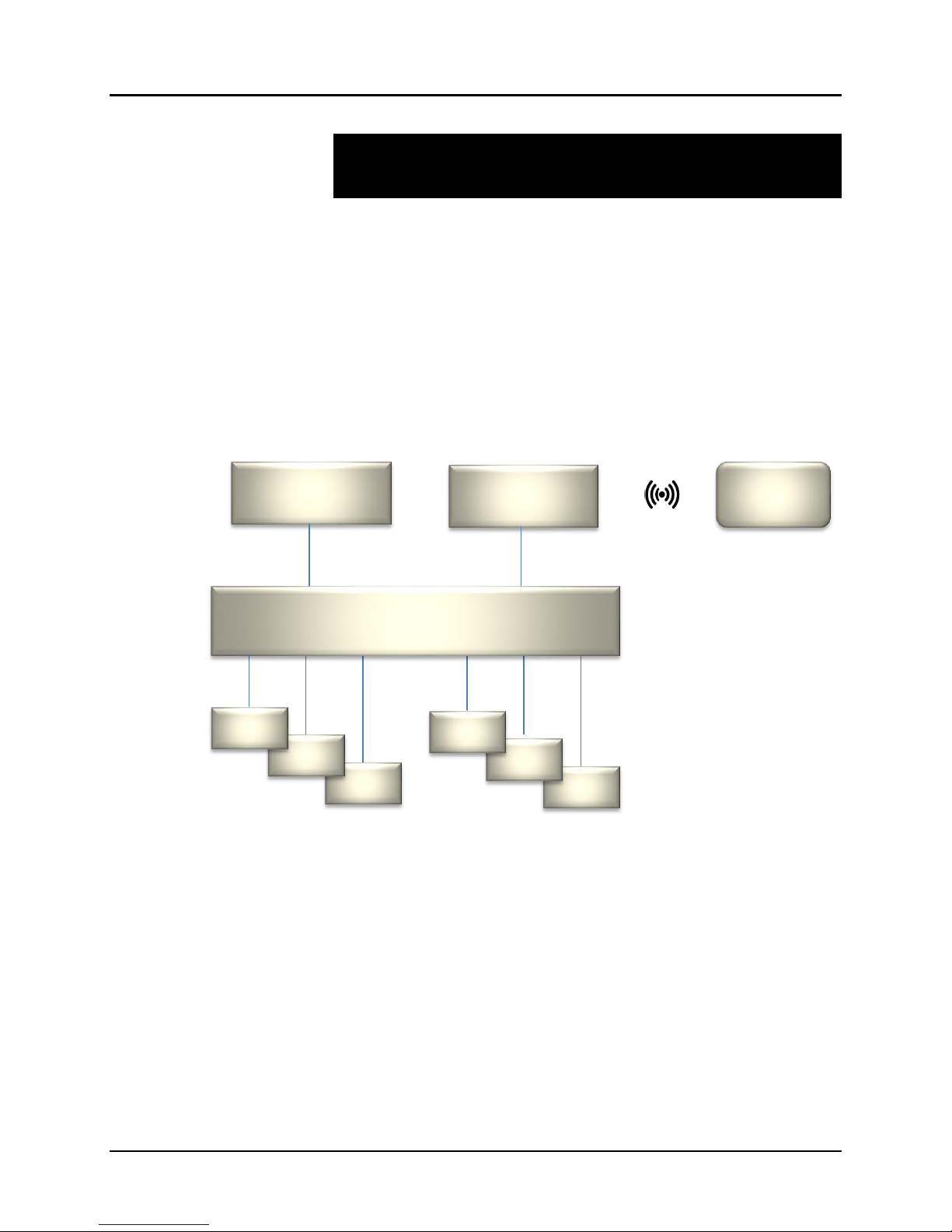
When installed on a local area network (LAN), the MuxLab Pro Digital Network
Controller can scan the LAN for MuxLab products and allows the user to autodiscover, configure and control these products through an Ethernet Web interface.
An Application Program Interface (API) is available supporting a number of third
party partner control applications running on smartphones and tables.
Router (w/WiFi)
PoE (PSE) Ethernet Switch
Figure 1: System Overview
Tablet or
Applications include but are not limited to commercial and residential AV systems,
classroom projector systems, digital signage, video wall systems, boardroom systems,
multi-room systems, classroom training, retail systems, collaborative PC systems, and
medical information systems.
Page 5
© MuxLab Inc. ProDigital Network Controller (MNC)
1.2.
Features
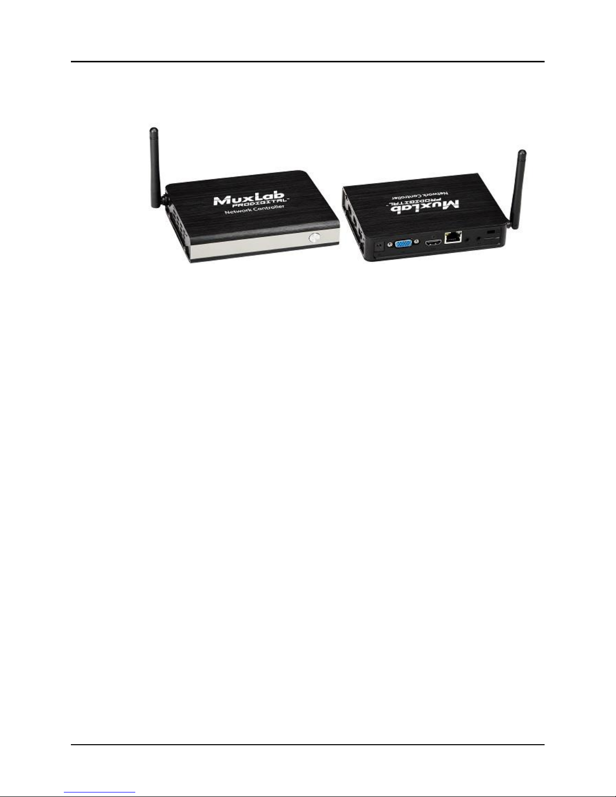
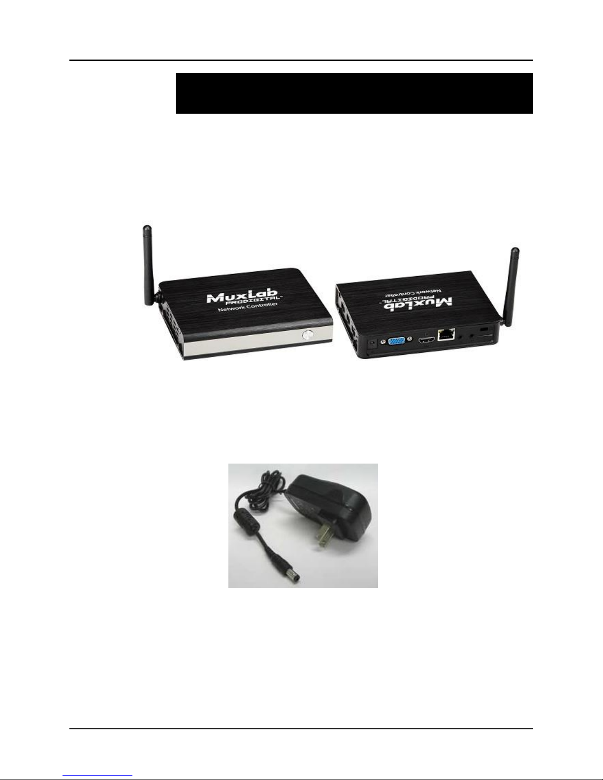
(Front View) (Rear & Side View)
Figure 1: Pro Digital Network Controller
Front Panel
Power LED
Power button
Back Panel
VGA video out port
HDMI video out port
LAN port (RJ-45 jack)
Audio in (3.5 mm)
Audio out (3.5 mm)
Micro SD memory slot
K lock
Power connector
Side Panel
Three (3) USB 2.0 ports
Page 6
© MuxLab Inc. ProDigital Network Controller (MNC)
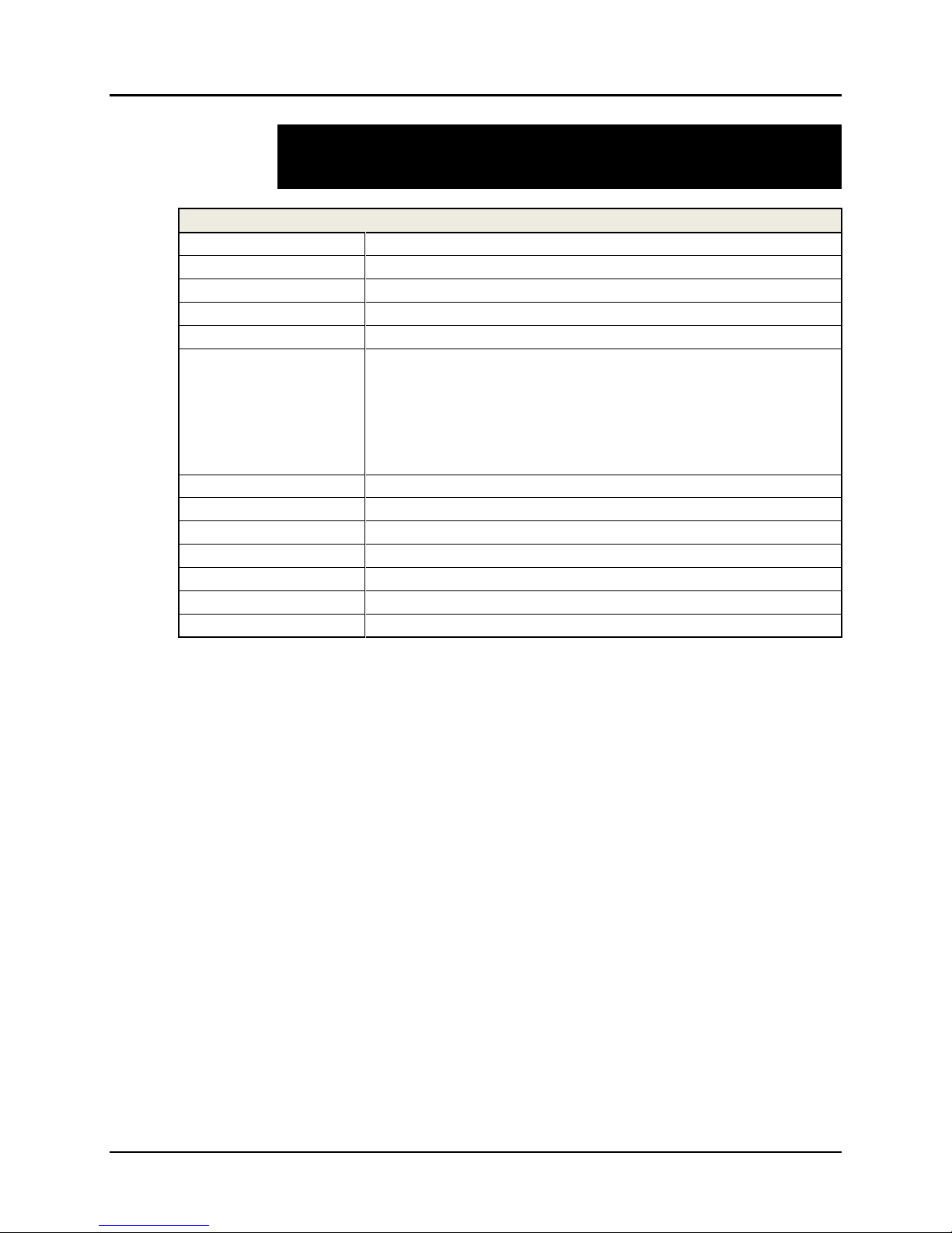
2.
MuxLab ProDigital Network Controller
CPU
Intel Z3735F
Memory
2GB DDR3
BIOS
AMI BIOS
VGA
Resolution up to 1920 x 1200
Keyboard and Mouse
USB keyboard and mouse (sold separately)
Peripherals
• USB 2.0 ports (3x)
• micro SD slot (1x)
• Network interface (1x)
• VGA Video out port (1x)
• HDMI Video out port (1x)
• Audio in via 3.5mm port (1x)
• Audio out via 3.5mm port (1x)
Operating System
Ubuntu 14.04 LTS
Operating Temperature
5 ºC to 50 ºC
Dimensions
4.52 x 4.52 x 1.4 inch (115 x 115 x 35 mm)
Weight
1.1lbs (0.5kg)
Accessories Included
External Power Adaptor
Regulatory
FCC, CE, RoHS, WEEE
Order Information
500811 Pro Digital Network Controller
Technical Specifications
Table 1: Technical Specifications
Page 7
© MuxLab Inc. ProDigital Network Controller (MNC)
3.
3.1.
Installation and Use
Part List
The MuxLab Pro Digital Network Controller comes with the following parts:
• Base unit (1x)
• External Power Adapter (1x)
Please verify that both parts are present before proceeding.
Figure 2: Base Unit
Figure 3: External Power Adaptor
Page 8
© MuxLab Inc. ProDigital Network Controller (MNC)
3.2.
A
1
A
2
A
3
A
4
A
5
A
6
A
7
A
9
A
8
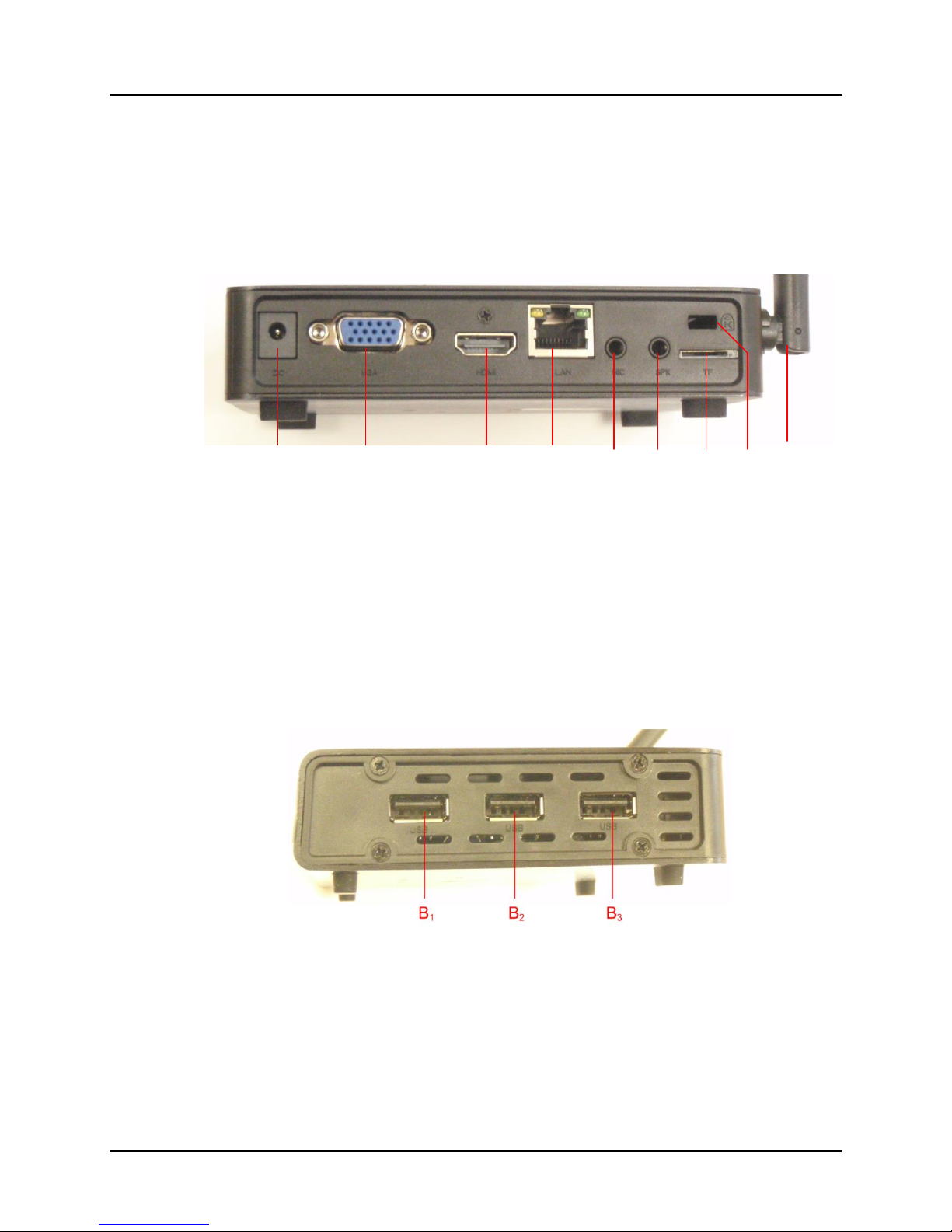
Product Overview
The external connections and connection indicators of the MuxLab Pro Digital
Network Controller are detailed in Figure 4 and Figure 5. Please familiarize yourself
with them before installing the unit.
Figure 4: Rear Panel
A1 = DC Power
A2 = VGA video out
A3 = HDMI video out
A4 = RJ45 Ethernet
A5 = Audio in
A6 = Audio out
A7 = Micro SD Memory Slot
A8 = K Lock
A9 = Wifi antenna (not supported in current software release)
Figure 5: Side Panel
B1 = USB 2.0 #1
B2 = USB 2.0 #2
B3 = USB 2.0 #3
Page 9

© MuxLab Inc. ProDigital Network Controller (MNC)
3.3.
Installation Procedure
Note that the examples below assume that the Ethernet Switch used does not support
WiFi, and a Router with WiFi capability is required in order to communicate with
smartphones and tablets for control purposes. Note that the WiFi antenna on the
MuxLab Controller is not supported in the current software release.
Setting the Ethernet Switch & Router to the same Subnet as MuxLab Devices:
The MuxLab Pro Digital Network Controller comes with a default static IP address of
192.168.168.50 (with DHCP disabled). The MuxLab AV over IP Transmitters and
Receivers are set to support DHCP by default. When no DHCP server is available the
AV over IP Transmitters and Receivers fallback to a static IP address of
192.168.168.55 (for the 500752, 500753, 500754 and 500756 Transmitters) and
192.168.168.56 (for the 500752, 500753, 500754 and 500756 Receivers), and
192.168.168.58 (for the 500758 and 500759 Transmitters) and 192.168.168.59 (for the
500758 and 500759 Receivers).
These MuxLab products (MNC, and the AV over IP Transmitters & Receivers) work
in conjunction with a PoE (PSE) Ethernet Switch (MuxLab recommends the Cisco
SG300 Series) and a Router of your choice with WiFi capability to be able to
communicate with a smartphone or tablet. The use of a smartphone or tablet to
manage the MuxLab devices with third party software applications is optional but is
the most common method of control and generally preferred, however MuxLab
devices may also be managed via the Pro Digital Network Controller web interface.
In order for the DHCP server within the Ethernet Switch to support the MuxLab
device subnet, set the static IP of the Ethernet Switch to 192.168.168.1 (recommended
setting). Refer to the Ethernet Switch manual for instructions on how to accomplish
this. MuxLab also has a guide specific to the Cisco SG300 Series, see document SE000819-A (Configuring Network Setting of the Ethernet Switch & MuxLab AV over
IP Devices), which can be found on MuxLab’s website under any of the AV over IP
product pages (as a download under the Operation Manual sub-category).
The Router with WiFi capability, must also be placed on the same subnet as the
MuxLab devices and it should be set with a Static IP address, we recommend using a
Static IP address of 192.168.168.2. Refer to your Router documentation on how to
accomplish this.
Setting MuxLab Devices, Ethernet Switch and Router to an Existing Subnet:
If the MuxLab AV over IP devices are being installed in an existing environment that
has a working subnet already configured that cannot be easily changed, then the
subnet of the MuxLab devices, the Ethernet Switch (if a new Ethernet Switch is
required), and the Router with Wifi (if a new Router is required) must be changed in
order to match the existing subnet. For this case we will use 192.168.2.x as an
Page 10

© MuxLab Inc. ProDigital Network Controller (MNC)
example subnet already in place and which must be supported. Note that this is only
an example and may not necessarily reflect your actual subnet address.
If the Ethernet Switch does not already reside in the example subnet of 192.168.2.x,
then set the static IP of the Ethernet Switch to a free static IP address (for the sake of
this example we will use an IP address of 192.168.2.1). Refer to the Ethernet Switch
manual for instructions on how to accomplish this. MuxLab also has a guide specific
to the Cisco SG300 Series, see document SE-000819-A (Configuring Network Setting
of the Ethernet Switch & MuxLab AV over IP Devices), which can be found on
MuxLab’s website under any of the AV over IP product pages (as a download under
the Operation Manual sub-category).
If the Router with WiFi does not already reside in the example subnet of 192.168.2.x,
then set the static IP of the Router to a free static IP address (for the sake of this
example we will use an IP address of 192.168.2.2). Refer to your Router
documentation on how to accomplish this.
The MuxLab AV over IP Transmitters and Receivers are set by default to support
DHCP, and will automatically be set to the subnet specified by the DHCP Server.
These units need only be physically connected into the network as described in their
respective Installation Guides and by using the 500811 Pro Digital Network Controller
to discover them. But before the MNC can be used, the new MNC subnet must also be
set.
To change the subnet of the MNC requires a two-step process:
Process 1: Configuring the IP address of the MNC
Process 2: Physically installing the MNC in the network
Note:
• An example subnet address of 192.168.2.x of the existing network on which the MNC will
be installed is assumed for this example process.
• The MNC comes with a static IP address of 192.168.168.50 and with DHCP disabled. This
process explains how to change it to the example subnet of 192.168.2.x.
Process 1: Configuring the IP address of the MNC
Refer to Figure 4 and Figure 5.
1. On the back panel of the MNC:
A. Plug the supplied power adaptor into the DC power jack. Ensure that the other
end of the power adaptor is plugged into a power socket.
B. Ensure that the power switch on the front of the unit is in the ON position
(front button • pressed in).
C. Connect one end of an Ethernet cable to the Ethernet port. Ensure that the
other end of the Ethernet cable is connected to a computer.
Page 11

© MuxLab Inc. ProDigital Network Controller (MNC)
Refer to Figure 6.
2. On the computer to which the MNC is connected, open up an Internet browser
(Explorer, Chrome, Firefox, etc.) and type the following address in the address bar
near the top of the screen:
http://192.168.168.50/mnc/
NOTE: mnc must be written in lower case
Figure 6: Internet Browser Entry
3. Press Enter on the keyboard. If the browser connects to the MNC, go to Step 7.
4. If the browser fails to connect to the MNC, a failure message will appear. Perform
the following steps (Steps 4 through 6) in order to set the computer to the same
subnet as the MNC, to be able to then change the MNC subnet (from Step 7
onward) to match the subnet of the existing installation (refer to Figure 7):
A. Move the mouse to the bottom of the screen and click on the Start button at the
lower left.
B. Click into the Search programs and files field just above the Start button and type
cmd. Press Enter on the keyboard.
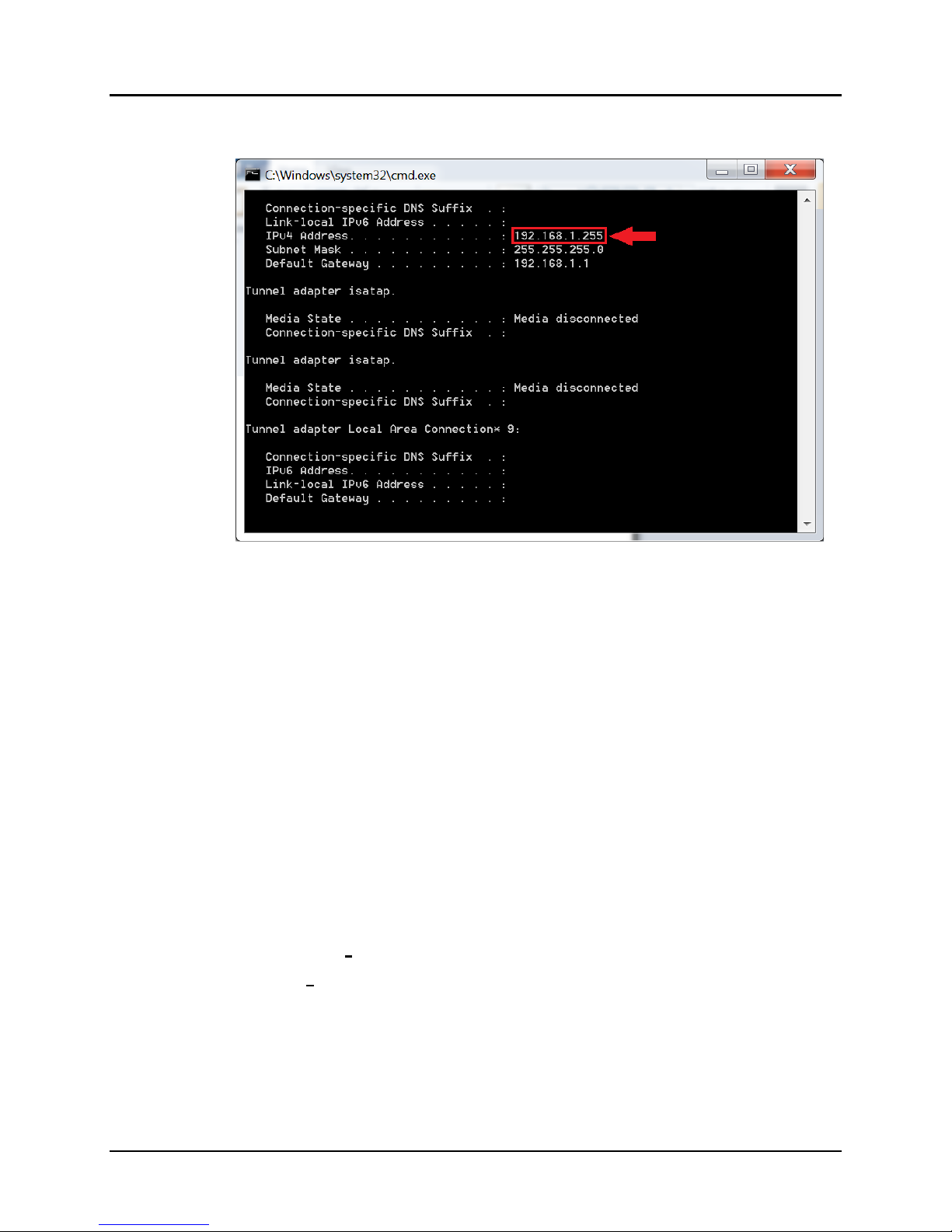
C. A DOS window will appear. Type ipconfig and press Enter on the keyboard.
Step 4A
Step 4B
Step 4C
Figure 7: Determining Computer IP Address
Page 12
© MuxLab Inc. ProDigital Network Controller (MNC)
The following screen will appear (Figure 8).
Figure 8: Computer IP Address
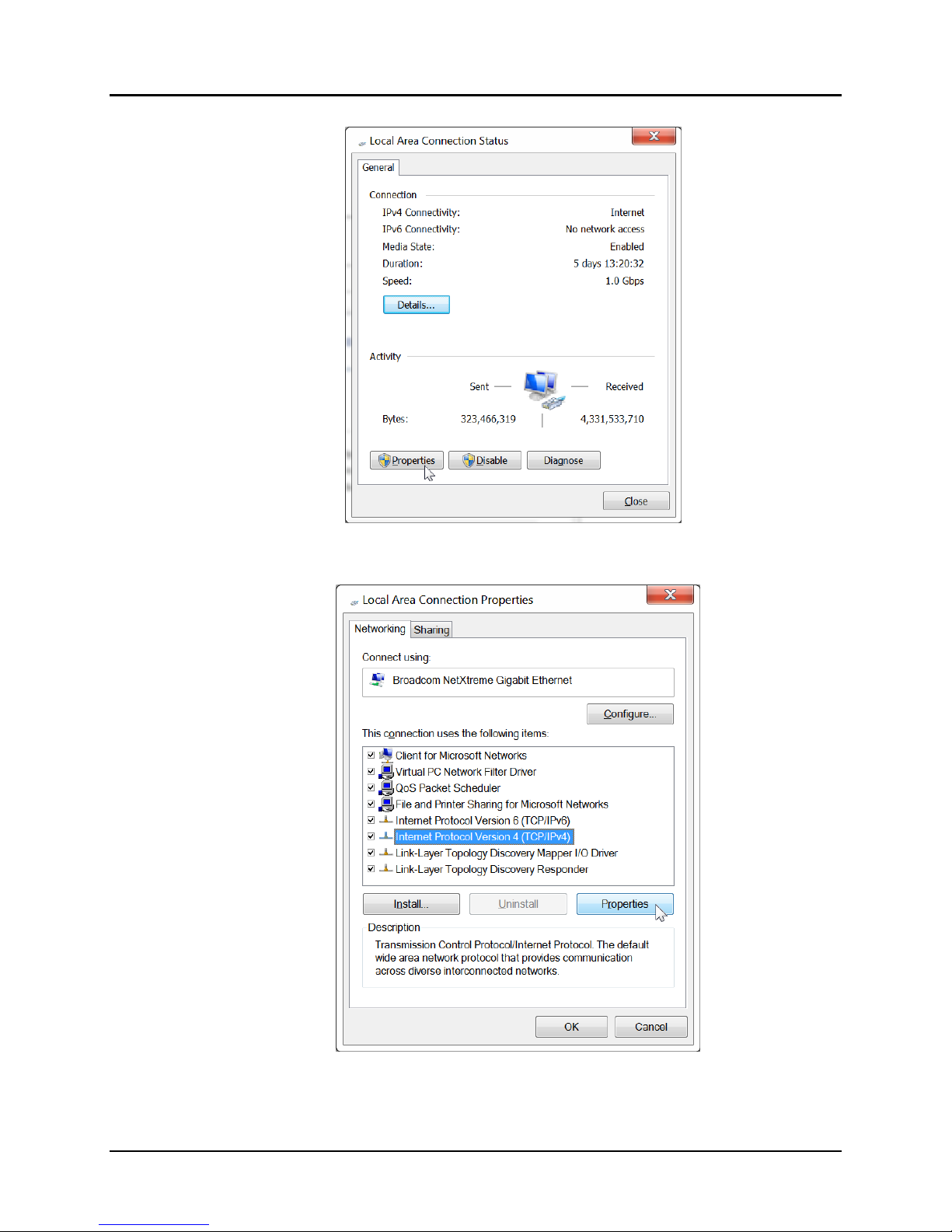
5. If the IPv4 Address (shown in the red box of Figure 8) does NOT begin with
the numbers 192.168.168.x, then perform the following steps (refer to Figure
9 through Figure 12):
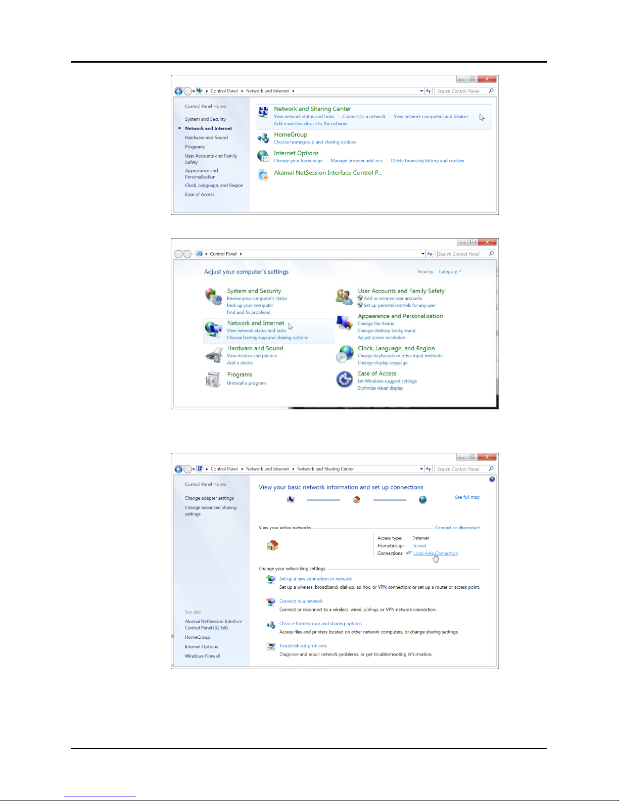
A. Type exit and press Enter on the keyboard.
B. Move the mouse to the bottom of the screen and click on the Start button at
the lower left.
C. Click on Control Panel
D. Click on Network and Internet
E. Click on Network and Sharing Center
F. Click on Local Area Connection
G. Click on Properties
H. Click on Internet Protocol Version 4 (TCP/IPv4). It will turn blue.
I. Click on Properties
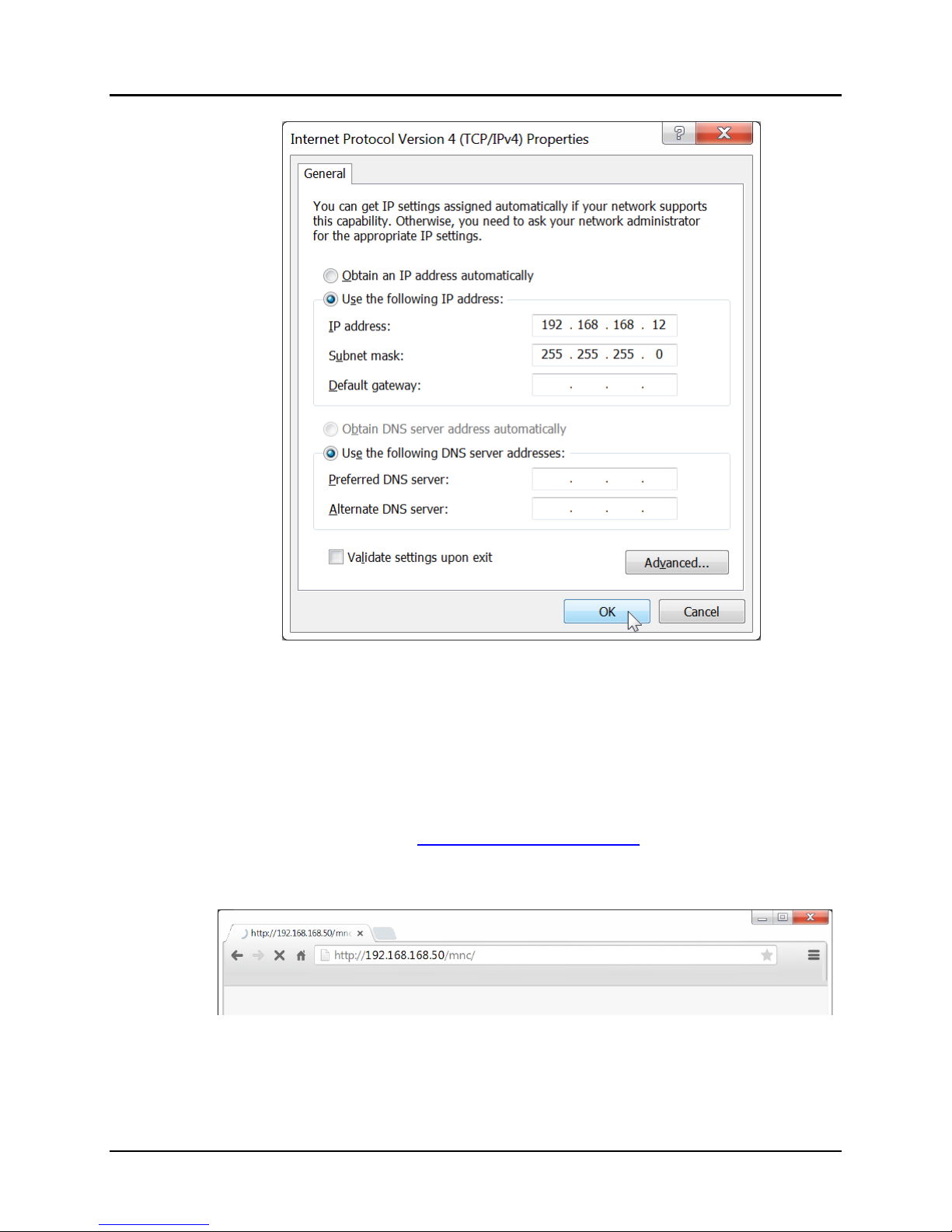
J. Click the Use the following IP address radio button.
K. In the IP address field, type the following:
192.168.168.x
Where x can be any number from 2 to 254 except for 50 (since 50 is the MNC
address). The example in Figure 12 has the PC set to a Static IP address of
192.168.168.12
Page 13

© MuxLab Inc. ProDigital Network Controller (MNC)
L. In the Subnet mask field, type the following:
255.255.255.0
M. Click on OK.
Step 5A
Steps 5B-5C
Figure 9
Page 14
© MuxLab Inc. ProDigital Network Controller (MNC)
Step 5D
Step 5E
Step 5F
Figure 10
Page 15
© MuxLab Inc. ProDigital Network Controller (MNC)
Step 5G
Steps 5H-5I
Figure 11
Page 16
© MuxLab Inc. ProDigital Network Controller (MNC)
The computer is now ready to communicate with the MNC.
Refer to Figure 13.
6. Open up an Internet browser (Explorer, Chrome, Firefox, etc.) and type the
following address in the address bar near the top of the screen:
NOTE: mnc must be written in lower case
Steps 5J-5K-5L-5M
Figure 12
http://192.168.168.50/mnc/
Figure 13: Internet Browser Entry
Page 17

© MuxLab Inc. ProDigital Network Controller (MNC)
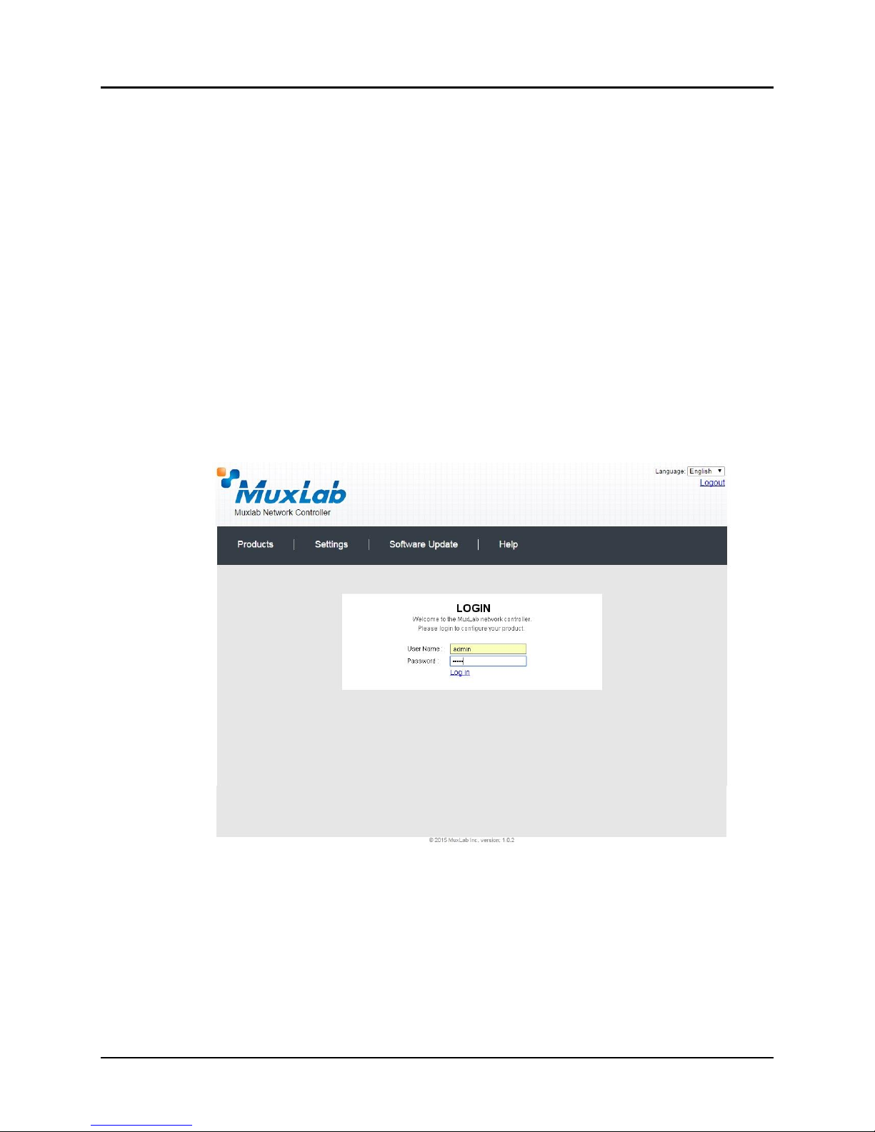
Refer to Figure 14.
7. The MuxLab Pro Digital Network Controller Web interface Login Screen will
appear.
Figure 14 Login Screen
8. In the User Name field, type admin. Use lower case.
9. In the Password field, type admin. Use lower case.
10. Click Log in.
Refer to Figure 15
Figure 15 Network Settings Screen
Page 18
© MuxLab Inc. ProDigital Network Controller (MNC)
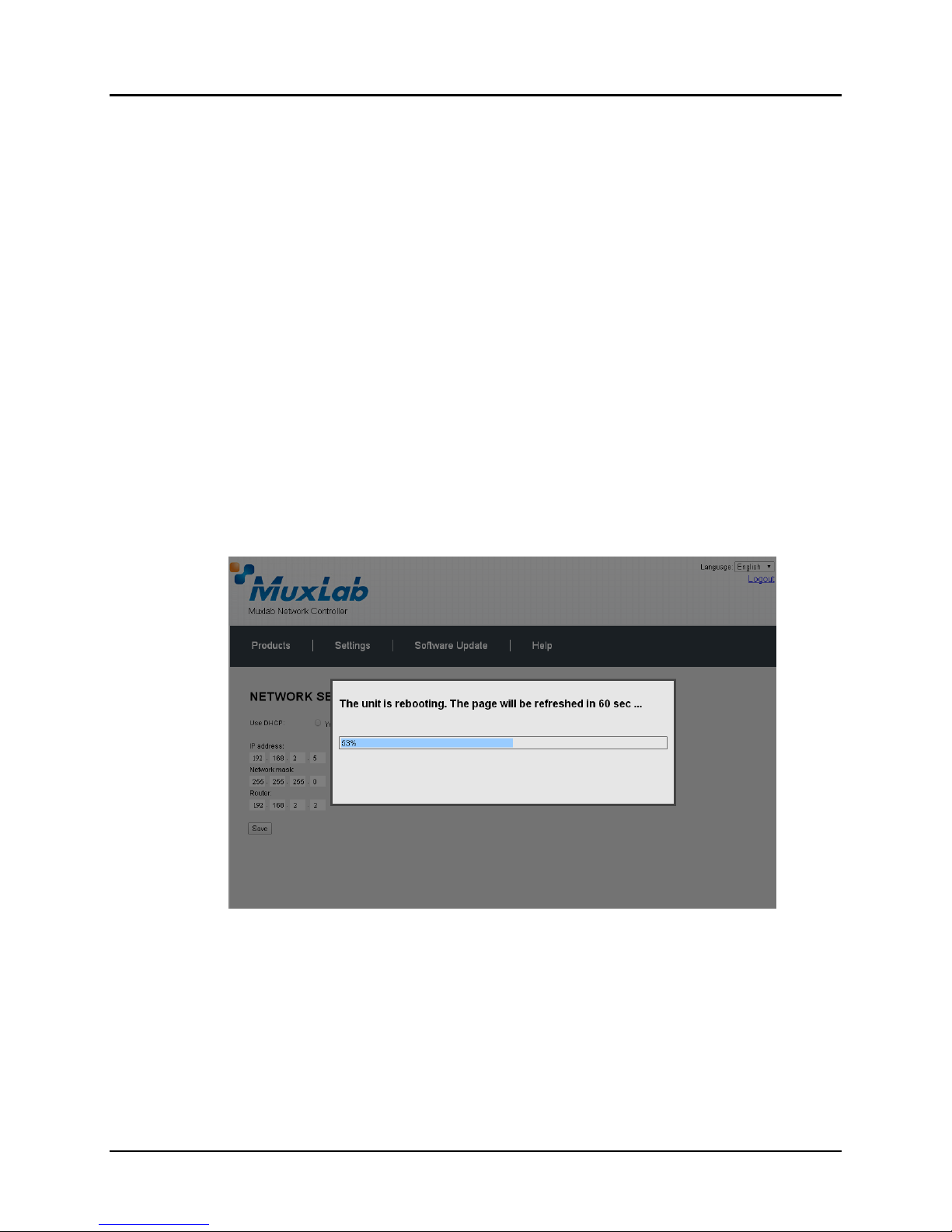
11. Click the Settings tab. The Network Settings screen will appear.
12. Next to Use DHCP, ensure that the No radio button is selected.
13. In the IP address field, type the first 3 entries of the IP address of the network
subnet on which the MNC will be installed, which in our example is 192.168.2.x.
For example, type the following in the MNC IP address field:
192.168.2.x
Where x in our example can be any number from 3 to 254, and since “1” was used
above for the Ethernet Switch and “2” was used for the Router, then for this
example we will select “5” for a Static IP address of 192.168.2.5, see Figure 15.
Error! Reference source not found. Just make sure the Static IP address for the
NC does conflict with the Static IP address of the Ethernet Switch and the Router
or any other Static IP address already pre-assigned in the given network.
14. In the Network mask field, type 255.255.255.0
15. In the Router field, type the IP address of the network Router (which in our
example is 192.168.2.2).
16. Click on Save. The MNC will reboot (Figure 16).
The MNC is now configured to work with your network router.
Process 2: Physically installing the MNC to the network
1. Disconnect the Ethernet cable from the computer and connect it to either the
Router or the Ethernet Switch. Ensure that the other end is still connected to the
MNC. Also make sure that the Router is connected to the Ethernet Switch.
Figure 16 MNC Reboot Screen
Page 19
© MuxLab Inc. ProDigital Network Controller (MNC)
3.4.
Ethernet Web Interface – Device Management
The Ethernet Web interface allows the user to manage the MNC and the AV over IP
product family of extenders remotely from a Windows based computer. Make sure the
computer is set to a Static IP address in the same subnet, which in our example is
192.168.2.x. Follow steps 4, 5 & 6 in section 3.3 on how to accomplish this, but set using
the subnet 192.168.2.x
Ensure that the computer is connected by an Ethernet cable to the network router on which
the MNC is physically installed. Open up an Internet browser (Explorer, Chrome,
Firefox, etc.) and type in the MNC IP address in the address bar near the top of the
screen, such as, which in our example is 192.168.2.5:
192.168.2.5/mnc/
NOTE: 192.168.2.x represents the first three IP address entries of the network subnet
on which the MNC is physically installed.
The MuxLab Network Controller Web interface Login Screen will appear (Figure 17).
In the User Name field, type admin. Use lower case.
In the Password field, type admin. Use lower case.
Click Log in.
You are now ready to manage the MuxLab Pro Digital Network Controller.
Figure 17 Login Screen
Page 20
© MuxLab Inc. ProDigital Network Controller (MNC)
Model
Type
Resolution
Features
Pages
500752
HDMI
1080p/60
IR + PoE
22-39
500753
HDMI
1080p/60
RS232+IR+PoE
40-58
500754
HDMI (Video Wall Capable)
1080p/60
RS232+IR+PoE
59-81
500755
Audio
2 Ch Audio
RS232+IR+PoE
82-100
500756
SDI
3G-SDI
RS232+IR+PoE
101-119
500757
HDMI
1080p/30
RS232+IR+PoE
120-135
500758
HDMI
4K/30
Audio+RS232+IR+PoE
136-152
500759
HDMI (Video Wall Capable)
4K/30
Audio+RS232+IR+PoE
153-173
500755AMP
Audio
2 Ch Audio
w/AMP
RS232+IR+PoE(TX)
174- 192
500762
HDMI
1080p/60 &
4K/60
USB+RS232+IR+PoE
193-210
Extender Models
The MuxLab Pro Digital Network Controller is designed to work with various
MuxLab Extender models (refer to Table 2).
All Extender models are controlled using MuxLab’s Network Controller software,
although the setup for each differs from model to model.
NOTE:
On the following pages, the controls for each Extender model are presented
separately. Please locate your Extender model in Table 2 and refer to the pages
that describe its operation. There is no need to read the remainder of this manual
in its entirety, each Extender section is complete and self-contained.
Table 2: Extender Models
Page 21
© MuxLab Inc. Extender Model 500752
Extender Model 500752
Products Screen
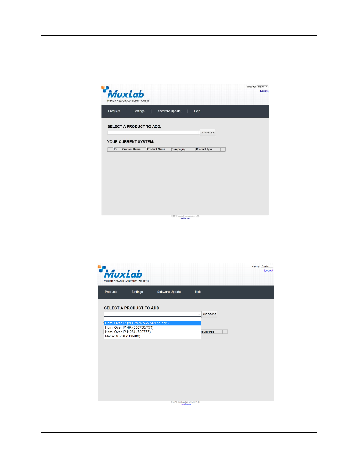
Once the user has logged in, the Products screen will appear (Figure 18).
Figure 18: Products Screen – Initial View
In the SELECT A PRODUCT TO ADD: drop down box, select Hdmi Over IP
(500752/753/754/755/756) and then click on ADD DEVICE (Figure 19).
Figure 19: Products Screen – Selecting a Product
Page 22
© MuxLab Inc. Extender Model 500752
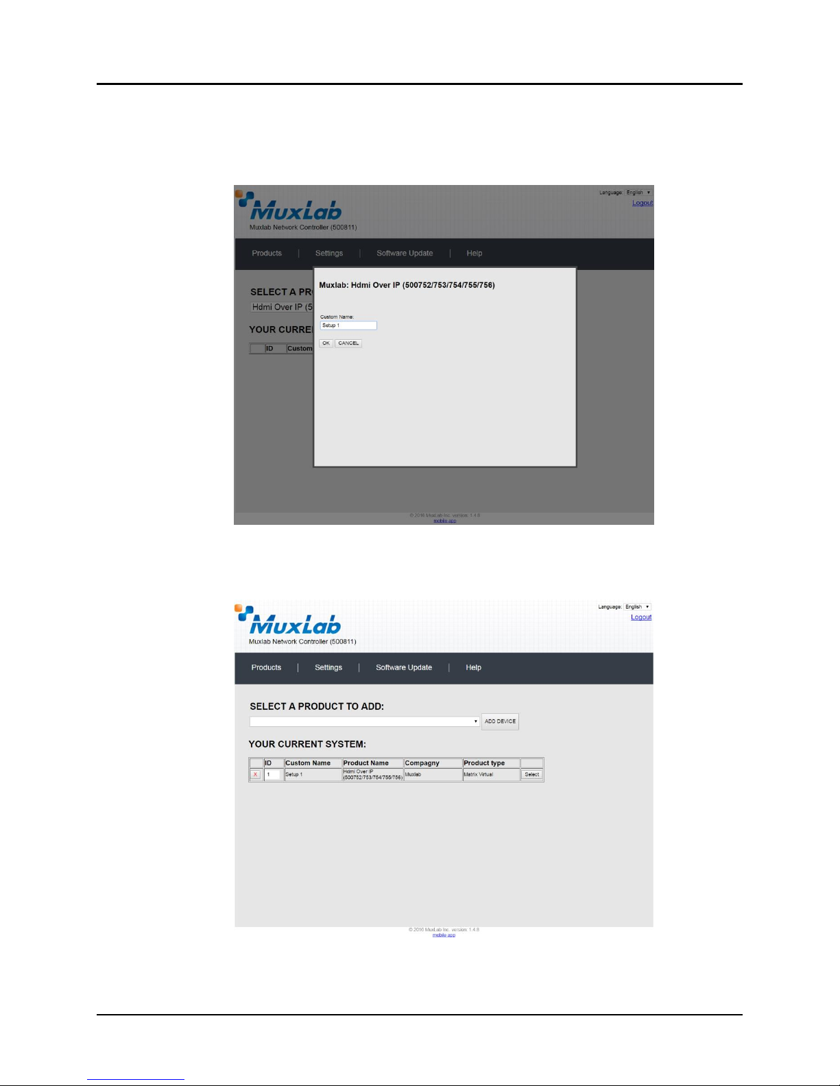
A dialog box appears asking the user to provide a custom name for the selected
product (Figure 20). The user then types a name in the Custom Name: field and clicks
on OK. Note that if the user decides to click on CANCEL, the previous screen
appears (Figure 19), without a product being added.
Figure 20: Products Screen – Naming a Product
The custom name has been added to YOUR CURRENT SYSTEM (Figure 21).
Figure 21: Products Screen – Your Current System Selection
Page 23
© MuxLab Inc. Extender Model 500752
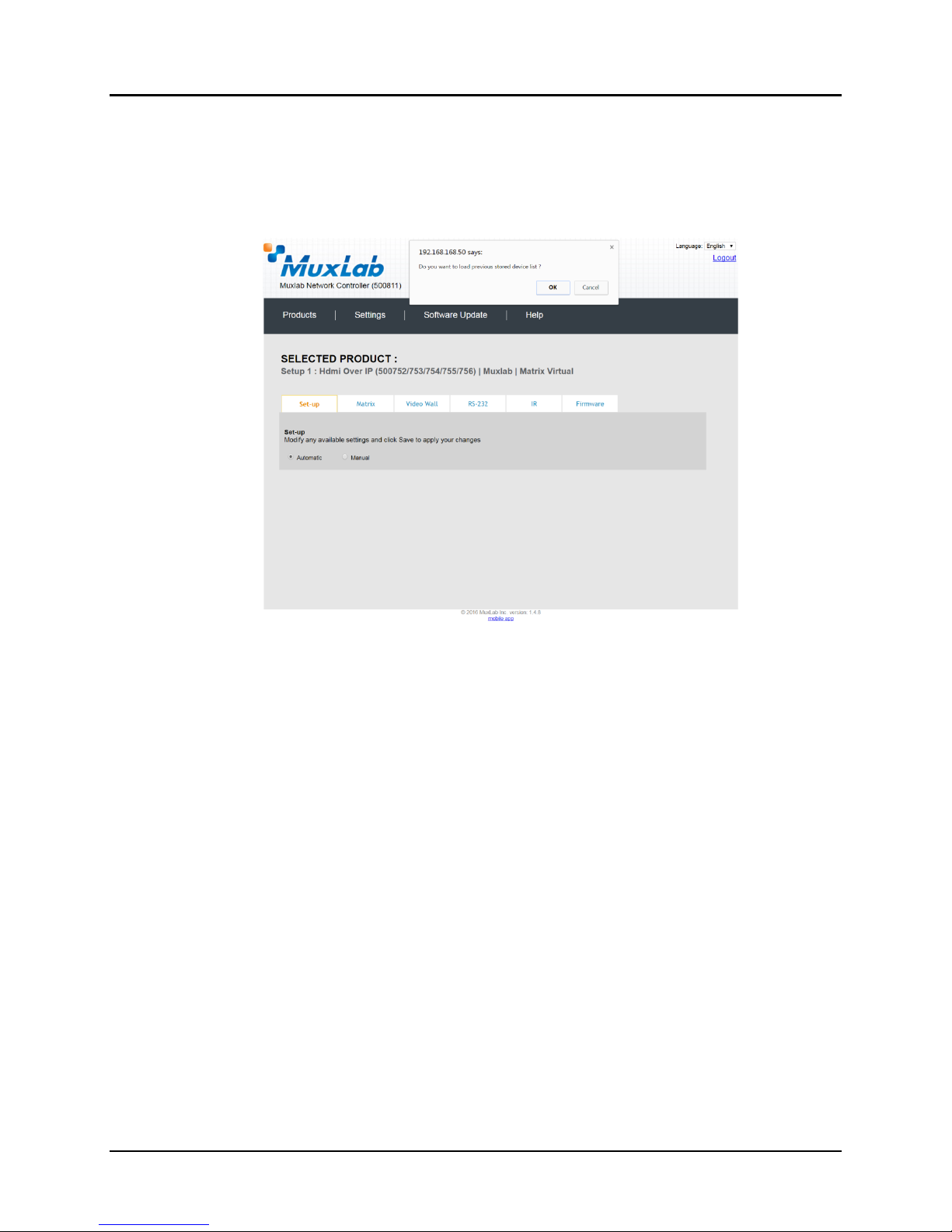
The user can change the ID of each row by modifying the ID field. The user can also
delete the entire row completely by clicking the X next to it.
To configure a given product, the user clicks on Select, which brings up a multitabbed screen (Figure 22).
By default, a dialog appears asking the user to load a previously saved device list (in
case such a list has already been stored). This dialog will appear even if no device list
has been previously saved.
Six tabs appear within the Products screen:
1. Set-up
2. Matrix
3. Video Wall
4. RS-232
5. IR
6. Firmware
Figure 22: Products Screen – Load Dialog
Page 24
© MuxLab Inc. Extender Model 500752
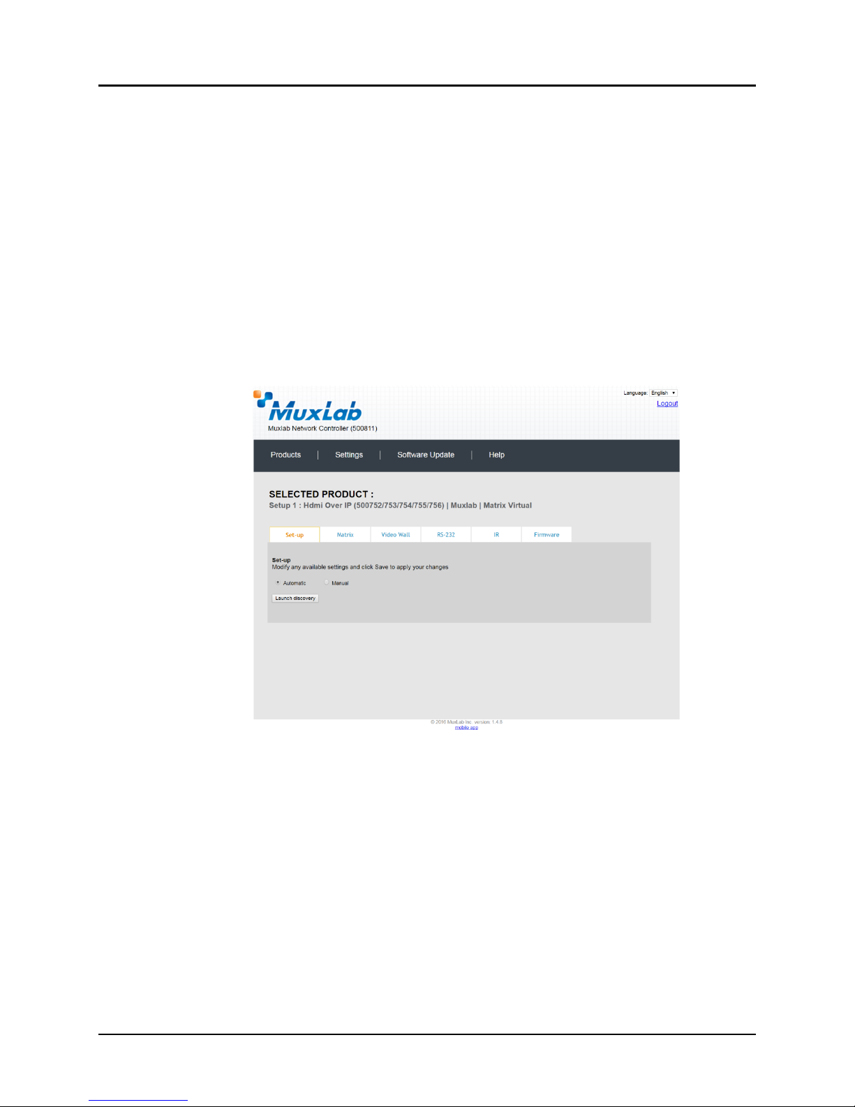
1. Products Screen - Set-up Tab
The Set-up tab offers the user two options for the type of set-up allowed:
Automatic or Manual.
Automatic means that the software will scan the system for every dip-
switch enabled device. The software will then override its manual dipswitch address settings and place these units under software address
control. (Automatic is recommended).
Manual means that the software will allow the manual dip-switch address
settings of any found device to remain active.
After selecting Automatic or Manual, click on Launch discovery (Figure 23).
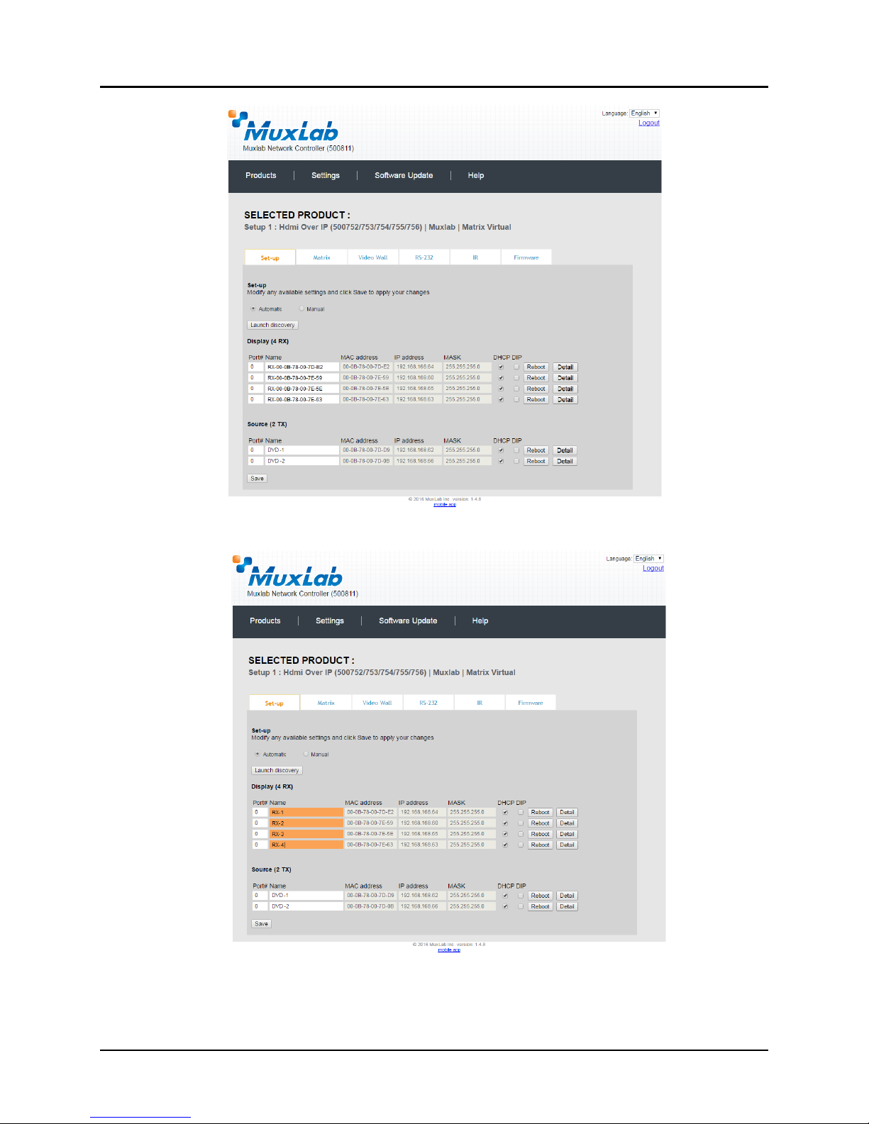
The system will scan the network for all source side devices (500752 transmitters) and
display side devices (500752 receivers), and will display the scan results in tabular
form (Figure 24).
Each 500752 transmitter and receiver can be assigned an arbitrary descriptive name,
normally reflecting the end device that it is terminated to. To change the name of any
Display (RX) or Source (TX) device, click the Name field to edit its contents. Several
Name fields can be edited before saving changes, as shown in Figure 25 (orange
highlighted fields).
Figure 23: Products Screen – Set-up Tab
Page 25
© MuxLab Inc. Extender Model 500752
Figure 24: Products Screen – Set-up Tab
Figure 25: Name Editing
Page 26
© MuxLab Inc. Extender Model 500752
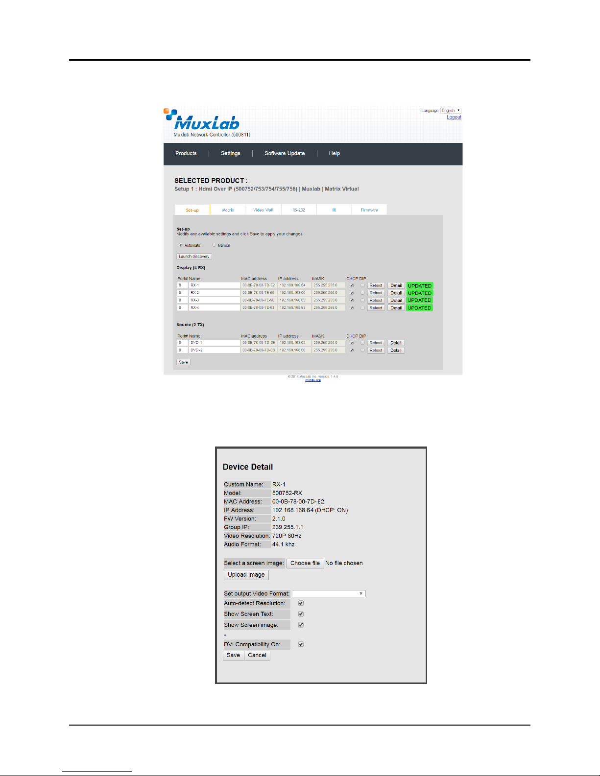
To save all name changes, click on Save. A green UPDATED tag will appear next to
newly changed names (Figure 26).
Figure 26: Saving Name Changes
To view and modify component parameters, click on the Detail button next to the
given component. A dialog appears (Figure 27).
Figure 27: Device Detail Dialog
Page 27
© MuxLab Inc. Extender Model 500752
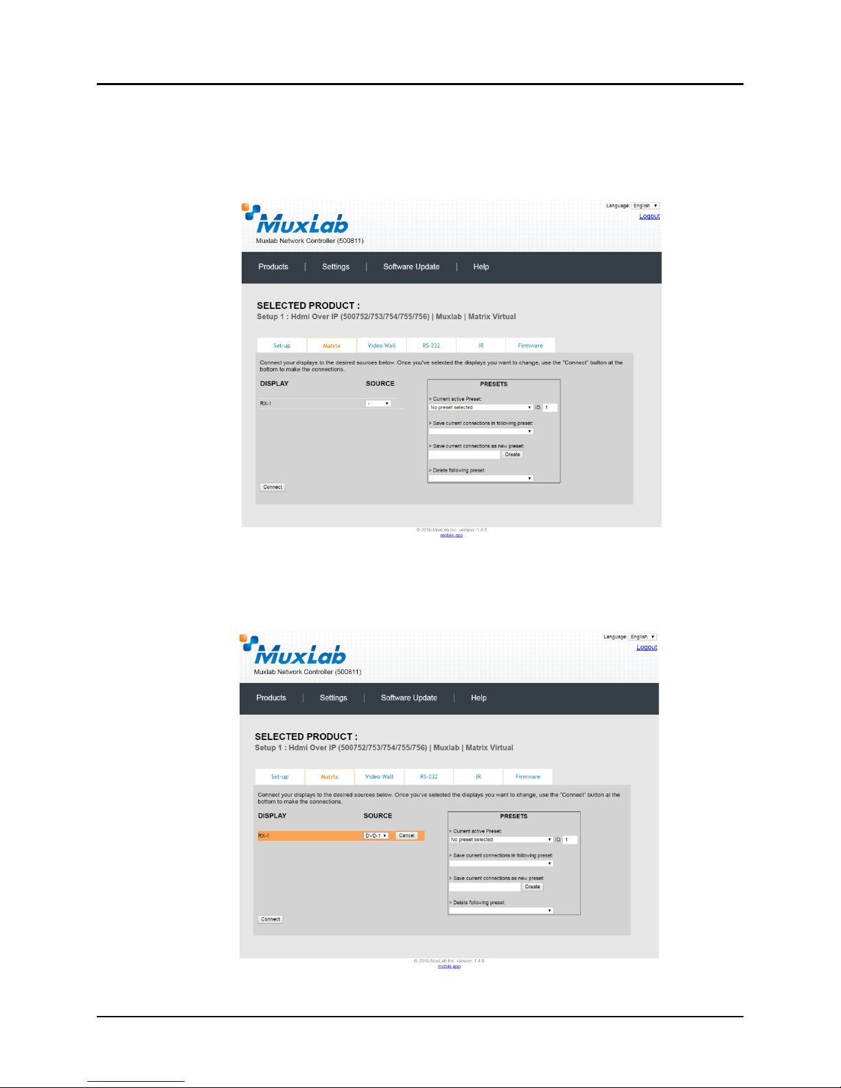
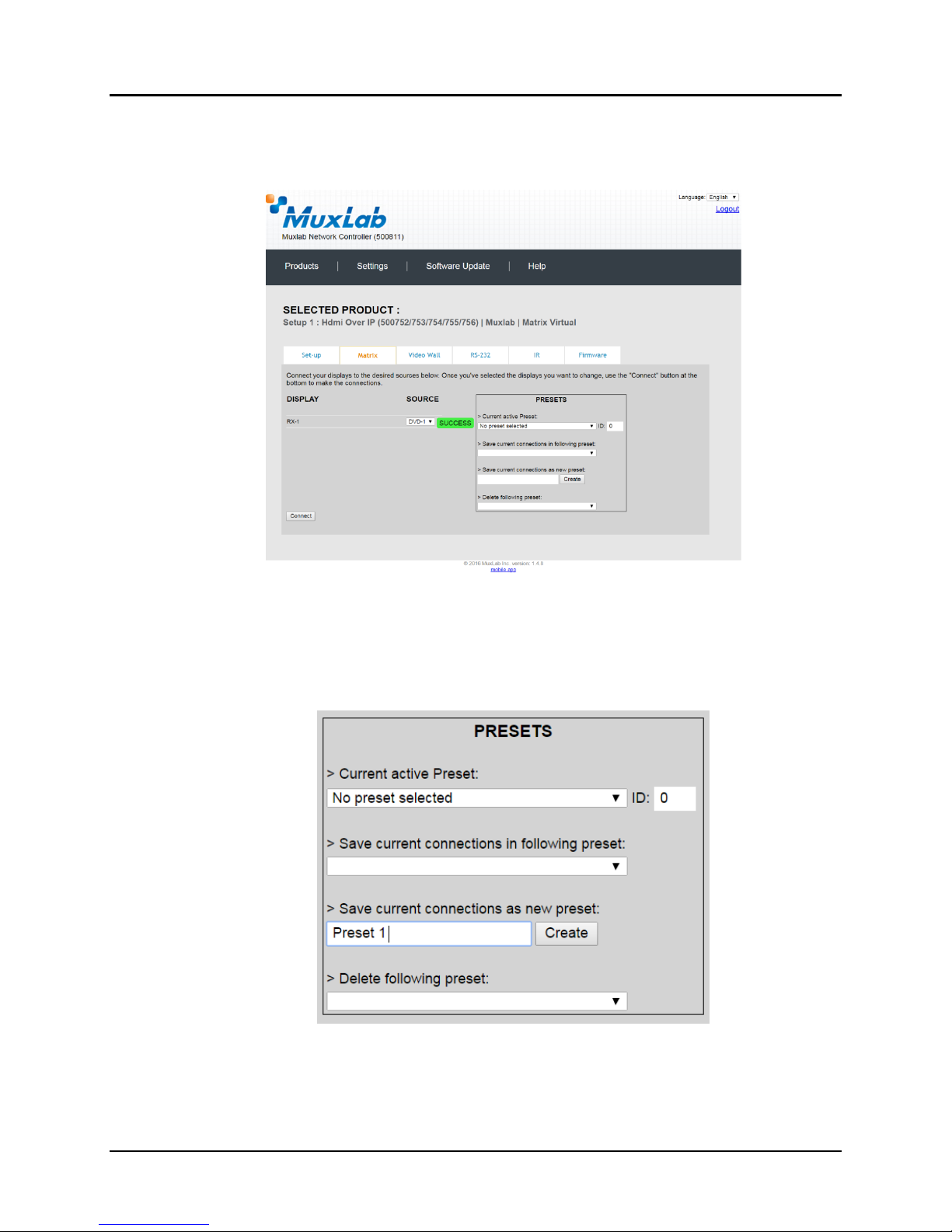
2. Products Screen - Matrix Tab
The Matrix tab of the Products screen allows the user to connect any Display to any
Source. The user also has the option of using Presets to save connection schemes
(“Presets”), as well as to edit and delete existing presets (Figure 28).
Figure 28: Matrix Tab
To connect a display to a source, the user first clicks on the drop-down list next to the
given display (for example “RX-1”) and selects which source to connect it to
(Figure 29).
Figure 29: Change Connection
Page 28
© MuxLab Inc. Extender Model 500752
Once the selection is made (the user can change any or all connections between
displays and sources), the user clicks on Connect to finalize the change. A green
SUCCESS tag will appear next to the new or changed connection (Figure 30).
To create a new preset, the user clicks the > Save current connections as new preset
field (Figure 31) and types a name. This assigned preset name will be linked to the
existing connection scheme being shown within the Matrix tab.
Figure 30: Change Successful
Figure 31: Create New Preset
Page 29
© MuxLab Inc. Extender Model 500752
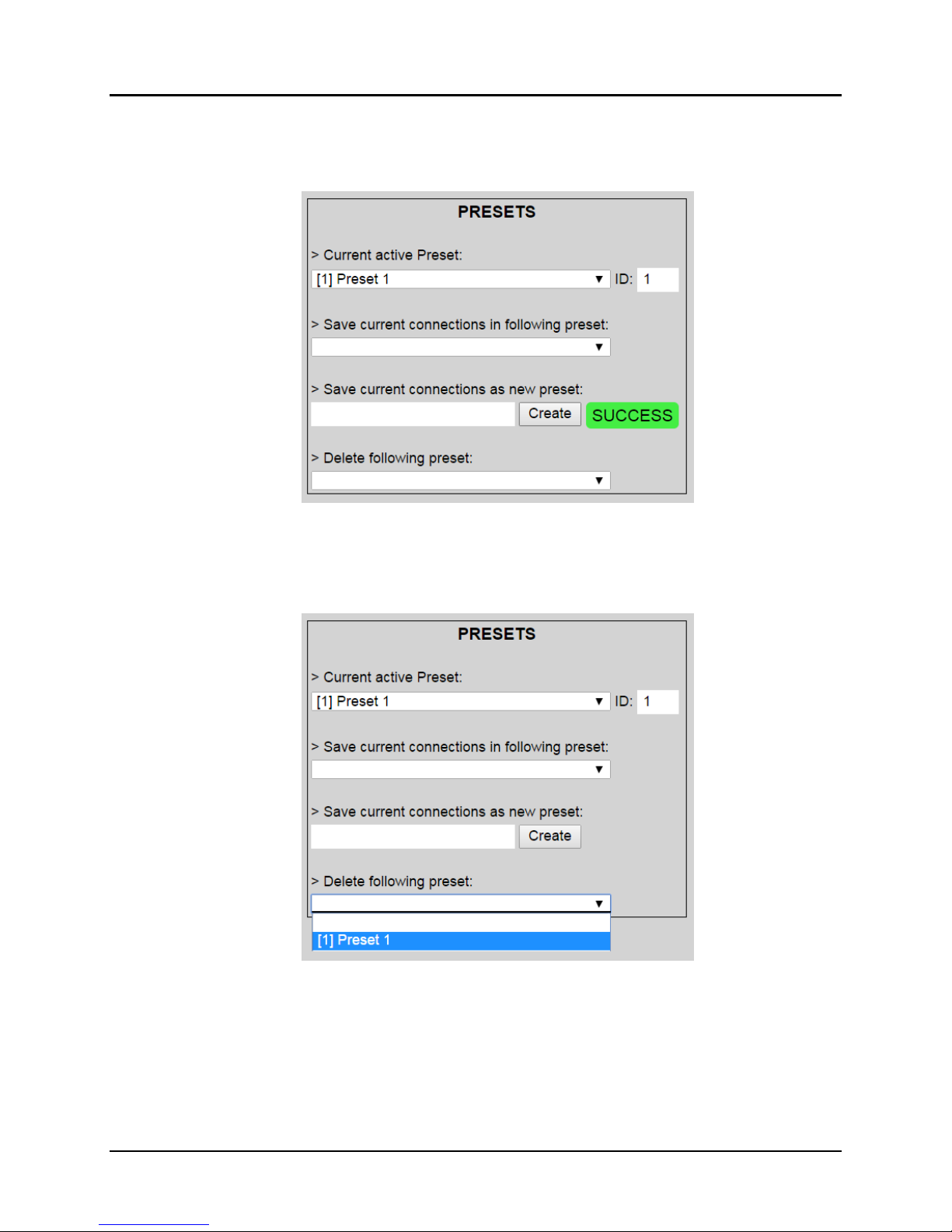
To save this preset, the user clicks on Create. A green SUCCESS tag will appear next
to the > Save current connections as new preset field and the newly created preset
becomes the Current active Preset (Figure 32).
Figure 32: Confirmation of New Preset
To delete a preset, the user clicks the > Delete following preset drop-down box and
selects a preset name from the list shown (Figure 33).
Figure 33: Delete Preset
Page 30
 Loading...