

MuxLab 500780 Quick Installation Manual
© MuxLab Inc. 94-000806-B SE-000806-B
8495 Dalton Road, Mount Royal, Quebec, Canada. H4T 1V5
Tel: (514) 905-0588 Fax: (514) 905-0589
Toll Free (North America): (877) 689-5228
E-mail: videoease@muxlab.com URL: www.muxlab.com
Specifications
Environment
HDMI 1.3a (Supports the 3D feature of HDMI 1.4)
Devices
DVD, plasma, projectors, monitors, TV, PC, laptops, servers
supporting HDMI.
Transmission
Transparent to the user.
Bandwidth
165 MHz
Signals
HDMI 1.3a protocol, HDCP
Connectors
Two (2) HDMI receptacle (for TX unit).
One (1) HDMI receptacle (for RX unit).
One (1) 3.5mm jack for IR sensor (for RX unit).
One (1) 2.5mm jack for IR emitter (for TX unit).
One (1) Mini USB Power Connector.
Note: HDMI cables not included.
Switch
Push button for pairing.
Latency
Less than 500msec
Compression
H.264
Bandwidth
Up to 15Mbps
Maximum Distance
Wireless transmission up to 100ft (30m), up to 1080p.
Based on a maximum length of 6.6ft (2m) of HDMI cable per end.
IR Frequency
Wideband 30KHz to 60KHz
Power Supply
One (1) 110-240V to 5VDC, 1A Micro USB power supply with
interchangeable blades per HDMI Wireless Extender unit.
Power Consumption
Transmitter: 4.5 Watt (Max) Receiver: 3.5 Watt (Max)
Temperature
Operating: 0° to 40°C Storage: -20° to 85°C
Humidity: Up to 95% non-condensing
Enclosure
Plastic
Dimensions
3.3” x 3.3” x 0.5” (84mm x 84mm x 13mm)
Weight
1lbs (0.45kg)
Compliance
Regulatory: FCC, CE, RoHS Flammability: 94V0
Warranty
2 years
Order Information
500780 HDMI Wireless Extender Kit
HDMI Wireless Extender Kit
500780
Quick Installation Guide
Overview
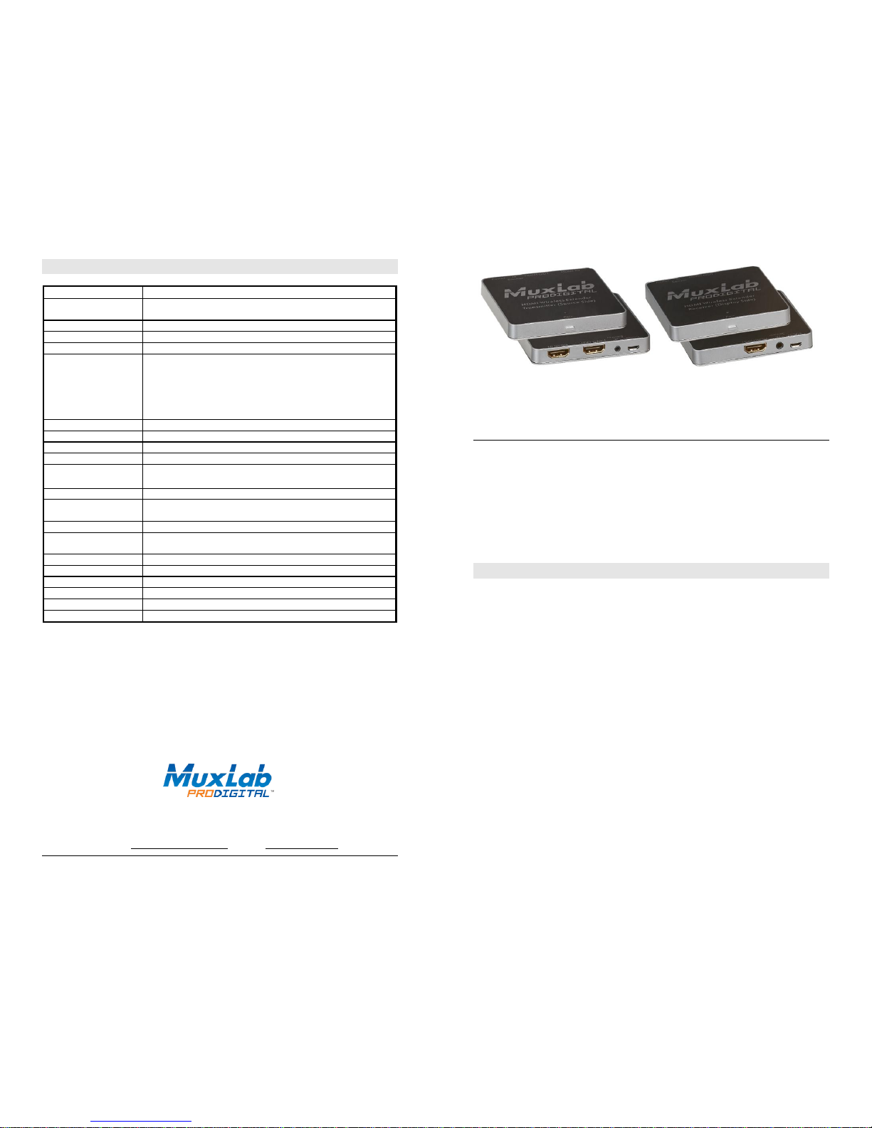
The HDMI Wireless Extender Kit (500780) allows HDMI equipment to be connected wirelessly up
to 100ft (30m) @ 1080p in a point-to-point configuration. The kit comes with one (1) Transmitter
and one (1) Receiver as well as an IR Emitter and an IR Sensor for remote control applications.
Applications
Applications include commercial and residential AV systems, classroom projector systems, digital
signage, boardroom systems, collaborative PC systems, Home Theatre, Showroom, and hard to
reach locations.
Installation
1. Identify the connectors on the Transmitter and Receiver as indicated on the product labels,
refer to the product diagram above.
2. Verify that the distance between the Transmitter and Receiver is within MuxLab
specifications (see Specifications table for more details). The Transmitter and Receiver form
private wireless network between both units, and do not require a customer’s router based
wireless network to operate.
3. To install the Transmitter:
3a. Connect the Transmitter HDMI-IN port to the HDMI video source with an HDMI
compliant cable.
3b. Connect the Transmitter HDMI-OUT port to the local HDMI display equipment
(optional) with an HDMI compliant cable.
4. To install the Receiver:
3a. Connect the Receiver HDMI-OUT port to the HDMI display equipment with an
HDMI compliant cable.
5. Connect the 5 VDC power supply to the Receiver first, and then plug the power supply
into an AC power outlet. Next connect the 5 VDC power supply to the Transmitter, and
then plug the power supply into an AC power outlet. If power is present, the red power
LED of the Transmitter and the Receiver will be illuminated.
Note: Power the HDMI Wireless Extender only after all connections are made.
© MuxLab Inc. 2016
6. Power the HDMI equipment, and pair the Transmitter and Receiver:
6a. Press the “Pair” button of the Receiver. You will see the message “Connecting through
Pairing…” on the screen.
6b. Press the “Pair” button of the Transmitter. You will see the message “Connecting…”
and then “Connected…”. The connection is now made.
6c. Verify the image quality.
7. This product supports unidirectional IR control. If infrared remote control is needed to
control the Source equipment from the Display, connect the IR Sensor to the 3.5mm Stereo
Jack of the Receiver and the IR Emitter to the 2.5mm Mono Jack of the Transmitter.
Note: You can differentiate the IR Sensor and the IR Emitter by looking at the 3.5mm and
2.5mm plugs. The IR Sensor is using a 3.5mm Stereo Plug (3 Contacts) and the IR
Emitter a 2.5mm mono plug (2 Contacts).
8. Position the IR Sensor so that it is directed to the hand-held remote control. For a clear IR
signal reception, aim the hand-held remote control at the top of the IR Sensor enclosure.
9. Position the IR Emitter as close as possible to the source’s IR Sensor (i.e. DVD player). For a
clear IR signal reception, the IR Emitter can be glued on the source’s IR Sensor. The IR
Emitter’s signal is transmitted from the side of the enclosure.
10. Do not cover the TX or the RX devices as not to block air circulation.
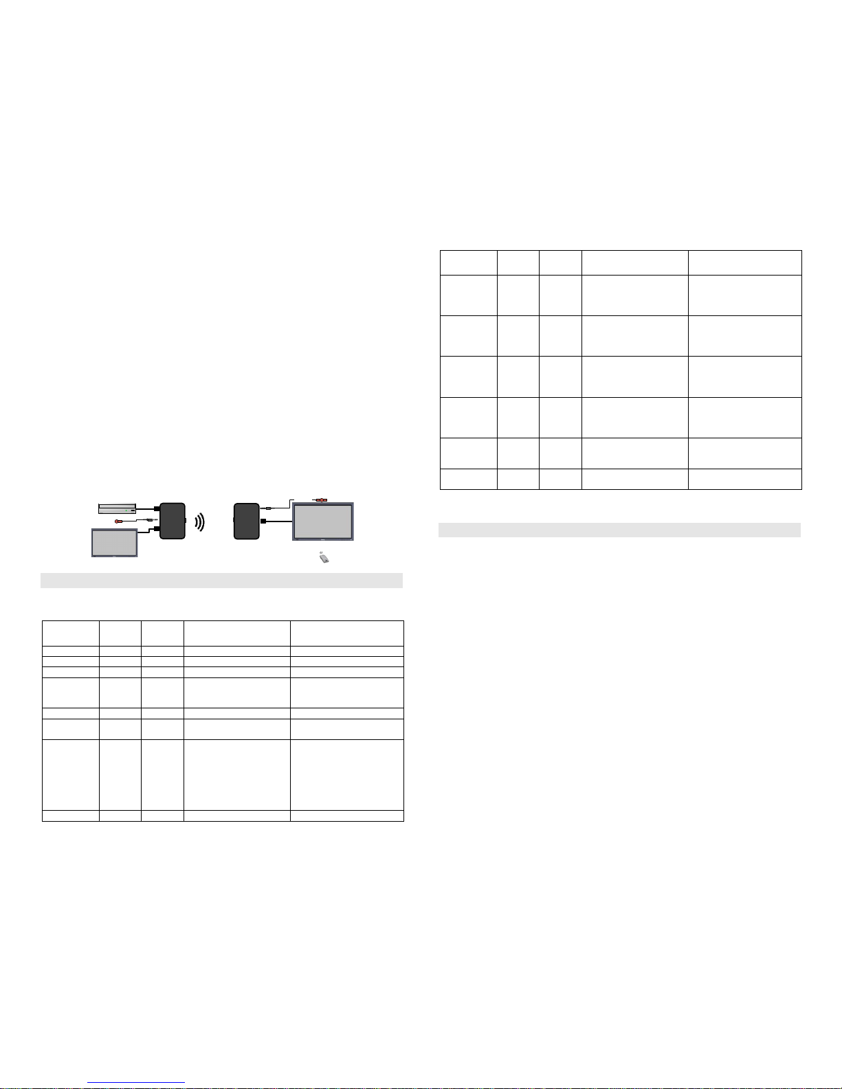
11. The following diagram shows the final configuration.
HDMI
HDMI
HDMI
DVD Player
Source
500780-TX
HDMI Wireless Encoder
500780-RX
HDMI Wireless Decoder
IR Sensor
Local Display
IR Emitter
Troubleshooting
The following table describes some of the symptoms, probable causes and possible solutions in regard to
the installation of the HDMI Wireless Extender Kit:
Symptom
TX LED
Rx LED
Probable
Cause
Possible
Solutions
No Image
OFF
OFF
No power
• Check power connections
No Image
ON
OFF
No power
• Check RX power connection
No Image
OFF
ON
No power
• Check TX power connection
No Image
ON
ON
Wireless interference
• Move the TX and RX devices
away from the wireless
source.
No Image
ON
ON
HDMI Cable
• Check the HDMI Cable.
No Image
ON
ON
Synchronization
• Check distance between TX
and RX.
Flickering
Image
ON
ON
Synchronization
• Check distance between TX
and RX.
• Check the HDMI Cable
Quality.
• Change the position of TX
and/or RX to get a better
reception.
No Sound
ON
ON
Display not properly set.
• Adjust display volume.
Symptom
TX LED
Rx LED
Probable
Cause
Possible
Solutions
Choppy sound
ON
ON
Synchronization
• Check distance between TX
and RX.
• Check the HDMI Cable
Quality.
Green or pink
hue
ON
ON
DDC communication
• Cycle power of the HDMI
Extenders.
• Check distance between TX
and RX.
Image flickers
when powering
up nearby
equipment
ON
ON
Interference
• Move the TX and RX devices
away from the interfering
source.
IR not
functioning
ON
ON
Remote control not directed
to the IR Sensor or IR
Emitter not directed to the
source.
• Make sure the IR Sensor is
directed towards the remote
and the IR Emitter to the
source equipment.
IR not
functioning
ON
ON
Interference from sunlight,
Fluorescent, Neon or Halogen
lights.
• Place the IR equipment away
for the interfering light
source.
IR not
functioning
ON
ON
Interference from RF
radiation from the TV
• Place the IR equipment away
for the RF radiation.
If you still cannot diagnose the problem, please call MuxLab Customer Technical Support at 877-6895228 (toll-free in North America) or (+1) 514-905-0588 (International).
Statements
FCC and Industry Canada:
This device complies with FCC Part 15 and Industry Canada license exempt RSS standard(s).
Operation is subject to the following two conditions: (1) this device may not cause interference,
and (2) this device must accept any interference, including interference that may cause undesired
operation of the device.
Le présent appareil est conforme aux CNR d'Industrie Canada applicables aux appareils radio
exempts de licence. L'exploitation est autorisée aux deux conditions suivantes : (1) l'appareil ne
doit pas produire de brouillage, et (2) l'utilisateur de l'appareil doit accepter tout brouillage
radioélectrique subi, même si le brouillage est susceptible d'en compromettre le fonctionnement
Industry Canada:
This device complies with Health Canada’s Safety Code. The installer of this device should ensure
that RF radiation is not emitted in excess of the Health Canada’s requirement.
Cet appareil est conforme avec Santé Canada Code de sécurité 6. L’installateur de cet appareil doit
s’assurer que les rayonnements RF ne sont pas émis au-delà de l’exigence de Santé Canada.
Changes or modifications not expressly approved by the party responsible for compliance could
void the user’s authority to operate the equipment.
Les changements ou modifications non expressément approuvés par la partie responsable de la
conformité pourraient annuler l'autorité de l'utilisateur à utiliser cet équipement.
 Loading...