

Page 1
2321 Cohen, Montreal, QC Canada. H4R 2N7
Tel: (514) 905-0588 Fax: (514) 905-0589
Toll Free (North America): (877) 689-5228
E-mail: [email protected] URL: www.muxlab.com
Specifications
Specifications
Environment
HDMI 2.0b and HDCP 2.2
Devices
Blu-Ray, projectors, monitors, TV, PC, laptops, and media servers supporting
HDMI.
Bandwidth
297 MHz
Signals
HDMI 2.0b protocol, up to 4K @ 60Hz (4:2:0)
Connectors
Note: Cables not included.
Connectors per TX and RX:
One (1) HDMI receptacle.
Two (2) RJ45S for Cat 5e/6 un sh ielded or shielded twisted pair (for 10GbE and
1GbE ports).
One (1) 3.5mm jack for IR emitter or IR sensor.
One (1) 3-pin terminal block connector for RS232.
One (1) 2.1mm locking power jack (for DC power).
Maximum Distance
Based on a maximum length of
6.6ft (2m) of HDMI cable per
end.
Supports up to 4K @ 60Hz (4:2:0) at 100m over Cat 6a/7 and at 55m over Cat 6
Note: When installed in an electrically noisy environment, an STP cable must be
used. Also, cross-connection reduces the effective distance depending on the
grade of twisted cable used.
Latency
Zero Latency
Compression
Uncompressed
Network Bandwidth
< 10Gbps
Network Requirement
10Gig Network XFI, IEEE 802.3
IR Frequency
38 to 56KHz
RJ45 Pin Configuration
Reverse Polarity Sensitive. Use
EIA/TIA 568A or 586B straightthrough wiring.
RJ45 Link
Pin 1 (R) Pin 2 (T)
Pin 3 (R) Pin 6 (T)
Pin 4 (R) Pin 5 (T)
Pin 7 (R) Pin 8 (T)
Cable
One (1) Cat 5e/6 or better twisted pair cable required
Power Source
Input: 100-240VAC @ 50-60Hz
Output: 12VDC
Includes multi-blades for US, UK and EU
Temperature
Operating: 0° to 40°C Storage: -20° to 85°C
Humidity: Up to 95% non-condensing
Dimensions
4.33” x 6.93” x 1” (11cm x 17.6cm x 2.5cm)
Weight
1.16 lbs (0.53 kg)
Compliance
Regulatory: FCC, CE, RoHS Flammability: 94V0
Warranty
3 years
Order Information
500768-TX HDMI over IP Uncompressed Transmitter, 4K/60
500768-RX HDMI over IP Uncompressed Receiver, 4K/60
Accessories
(These items are sold
separately)
500920 16-Port Rackmount Transceiver Chassis
500917 Wall Mount Transceiver Bracket Kit
500990 IR Emitter
500994 IR Sensor
HDMI over IP Uncompressed Extender, 4K/60
500768
Quick Installation Guide
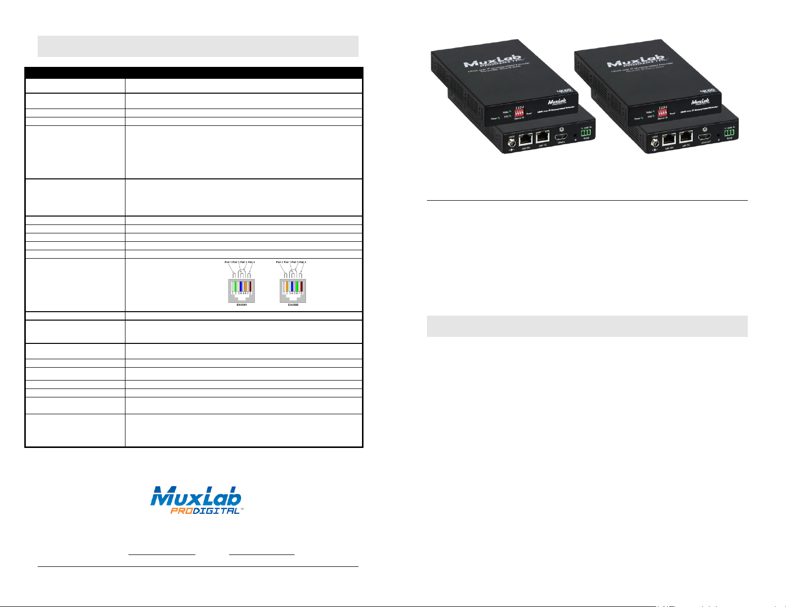
The HDMI over IP Uncompressed Extender, 4K/60 allows HDMI source equipment supporting up
to 4K (3840x2160) resolution @ 60Hz to be connected via Cat5e/6 cable up to 330ft (100m) from
a 10G Ethernet Switch, in point-to-point, point-to-multipoint and multipoint-to-multipoint
configurations. The Transmitter and Receiver, also each support a 1G Ethernet Switch port to
connect additional network devices, plus a directional IR port and RS232 port for remote control of
end devices. The MuxLab Pro Digital Network Controller (500811) is available to simplify
centralized configuration and control, software updates, and allows for management from the
MuxLab Control smartphone and tablet App, and third party control Apps. Applications include
commercial and residential AV systems, classroom projector systems, digital signage, boardroom
systems, collaborative PC systems, and medical information systems.
Installation
© MuxLab Inc. 94-000888-A SE-000888-A
1. Identify the connectors on the Transmitter and Receiver as indicated on the product labels, see the
above front and rear product views for further details.
2. Verify that the distance between the HDMI Transmitter and Receiver is within MuxLab
specifications (see Specifications table for more details).
3. To install the Transmitter:
3a. Connect the Transmitter to the HDMI video source with an HDMI compliant cable.
3b. If the application is point-to-point, then connect one (1) length of Cat 5e/6 (or higher)
grade UTP cable to the RJ45 LINK connector on the Transmitter. If transmitting over
the network, use a 10G Ethernet Switch between Transmitter and Receiver.
4. To install the Receiver:
4a. Connect the Receiver to the HDMI display equipment with an HDMI compliant cable.
4b. If the application is point-to-point, then connect one (1) Cat 5e/6 cable (or higher)
coming from the Transmitter, to the RJ45 LINK connector on the Receiver. If
transmitting over the network, use a 10G Ethernet Switch between Transmitter and
Receiver. You may use the 1G port of the TX and RX to connect additional
network devices (e.g. for managing purposes) if required. In both point-to-point
cases, ensure the TX and RX have the same Dip Switch setting.
5. If the configuration is a point-to-multipoint or multipoint-to-multipoint:
5a. You will need to use an Ethernet Switch with 10G ports and DHCP Server support. In
Page 2
addition IGMP Protocol support is required. Verify that the Ethernet Switch is
Symptom
Transmitter LEDs
Receiver LEDs
Probable
Cause
Possible
Solutions
Power
Link
Power
Link
No Image
OFF
OFF
OFF
OFF
No power
• Check power connections
No Image
BLINK
OFF
BLINK
ON
Booting
• Wait until booting process is
finished
No Image
ON
OFF
ON
OFF
No Ethernet Link
• Check Ethernet Switch Status
• Check UTP Cables
Info Screen
ON
OFF
ON
BLINK
UTP Cable
• Check the Transmitter UTP cable
Info Screen
ON
ON
ON
OFF
UTP Cable
• Check the Receiver UTP cable.
Info Screen
ON
BLINK
ON
BLINK
No Data
Connection
• Check if DIP Switch settings
match
Info Screen
ON
ON
ON
BLINK
Wrong setting on
Receiver
• Check DIP Switch address of the
Receiver
Choppy Video
ON
ON
ON
ON
Configuration
• Check cable length
• Check the HDMI Cable Quality
• Check if IGMP is enabled on the
Ethernet Switch
Image flickers
when powering
up nearby
equipment
ON
ON
ON
ON
Interference
• Use STP cables
IR not
functioning *
ON
ON
ON
ON
Interference from
sunlight,
Fluorescent,
Neon or Halogen
lights
• Place the IR equipment away for
the interfering light
IR not
functioning *
ON
ON
ON
ON
Interference from
RF radiation from
the TV
• Place the IR equipment away for
the RF radiation
configured correctly and that the DHCP Server and IGMP Protocol is enabled.
See the operating manual for more information about configuring the Ethernet Switch.
5b. Connect all Transmitters and Receivers to the Ethernet Switch.
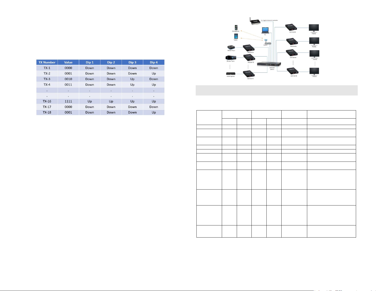
5c. Use the DIP Switches to select a unique Device ID address for each Transmitter present
on the network and configure each Receiver Device ID to the corresponding selected
Transmitter. To avoid Multicast address conflicts, please follow these settings when
using several Transmitters:
6. To power the Transmitter and Receiver, connect the included 12VDC power supply to each
Receiver and to an AC power outlet. Next, connect each Transmitter in the same manner. If
power is present, the green power LED on each Transmitter and Receiver will illuminate.
Note: Power ‘ON’ the HDMI over IP Uncompressed Extender, 4K/60 devices only after
all connections have been made.
7. Power ‘ON’ the HDMI equipment and verify the image quality.
8. This product supports IR pass-thru control. IR Emitter and Sensor are not included, and are
sold separately. If for example infrared remote control is needed to control the Source
equipment from the Display, connect the IR Sensor to the 3.5mm Stereo Jack of the Receiver
and the IR Emitter to the 3.5mm Mono Jack of the Transmitter. The IR port is directional,
ensure that the IR direction is properly configured via the unit web interface or via the
500811 Pro Digital Network Controller. Note: You can differentiate the IR Sensor and
the IR Emitter by looking at the 3.5 mm plug. The IR Sensor is using a Stereo Plug (3
Contacts) and the IR Emitter a mono plug (2 Contacts).
9. Position the IR Sensor so that it is directed at the hand-held remote control. For a clear IR
signal reception, aim the hand-held remote control at the top of the IR Sensor enclosure.
10. Position the IR Emitter as close as possible to the source’s IR Sensor (i.e. DVD player). For a
clear IR signal reception, the IR Emitter can be glued on the source’s IR Sensor. The IR
Emitter’s signal is transmitted from the side of the enclosure.
11. This product supports RS232 bidirectional communication. On the Transmitter, the RS232
port is configured as a DCE; and on the Receiver as a DTE. Please connect your RS232 cable
accordingly. Configure the RS232 communications setting via the device web interface or
500811 Pro Digital Network Controller.
12. Commands or messages may be sent via RS232 by connecting a PC to the RS232 port of the
500768, or over the network via IP. This communications is meant to be machine to machine.
13. The following diagram illustrates a typical LAN configuration.
Troubleshooting
The following table describes some of the symptoms, probable causes and possible solutions in regard to
the installation of the HDMI over IP Uncompressed Extender, 4K/60 Kit:
* IR Emitter and IR Sensor sold separately.
If you still cannot diagnose the problem, please call MuxLab Customer Technical Support at
877-689-5228 (toll-free in North America) or (+1) 514-905-0588 (International).
© MuxLab Inc. 2018
 Loading...