

MuxLab 500454-POE, 500454-POE-RX Quick Installation Manual
© MuxLab Inc. 94-000858-A SE-000858-A
8495 Dalton Road, Mount Royal, Quebec, Canada. H4T 1V5
Tel: (514) 905-0588 Fax: (514) 905-0589
Toll Free (North America): (877) 689-5228
E-mail: videoease@muxlab.com URL: www.muxlab.com
Specifications
Environment
HDMI 1.3a (Supports the 3D feature of HDMI 1.4).
Devices
DVD, plasma, projectors, monitors, TV, PC, laptops, servers
supporting HDMI.
Transmission
Transparent to the user.
Bandwidth
340 MHz.
Signals
HDMI 1.3a protocol.
Connectors
Cables not included.
One (1) HDMI receptacle.
One (1) RJ45S for Cat 5e/6 unshielded or shielded twisted pair.
Two (2) 3.5mm jacks for IR emitter and sensor.
One (1) DB9 Connector for RS-232.
Maximum Distance
Based on a maximum
length of 6.6 ft (2 m) of
HDMI cable per end.
Cat 5e/6: 230 ft (70 m) up to 1080P Deep Color
115 ft (35 m) for 4K; 3840 X 2160/24,25,30 Hz
Note: When installed in an electrically noisy environment, an STP
cable must be used. Also, cross-connection reduces the effective
distance depending on the grade of twisted cable used.
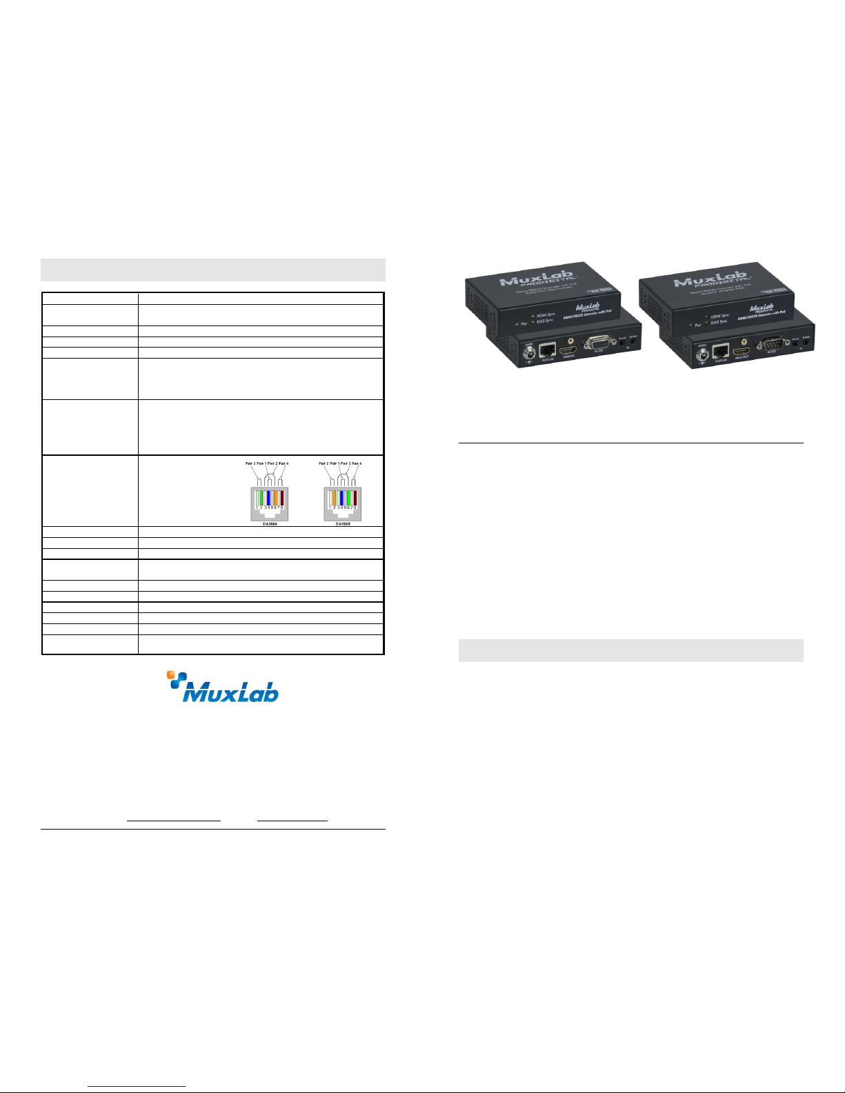
RJ45 Pin
Configuration
Reverse Polarity
Sensitive. Use EIA/TIA
568A or 586B straightthrough wiring.
RJ45 Link
Pin 1 (R) Pin 2 (T)
Pin 3 (R) Pin 6 (T)
Pin 4 (R) Pin 5 (T)
Pin 7 (R) Pin 8 (T)
Cable
One (1) Cat 5e/6 or better twisted pair cable required
Power Supply
One (1) 110-240V/48VDC power supply with interchangeable blades.
Power Consumption
Transmitter: 1.6 Watt Receiver: 3.2 Watt
Temperature
Operating: 0° to 40°C Storage: -20° to 85°C
Humidity: Up to 95% non-condensing
Enclosure
Metal
Dimensions
4.40” x 3.00” x 1.00” (11.2 x 7.6 x 2.5 cm)
Weight
1.4 lb (0.6 kg)
Compliance
Regulatory: FCC, CE, RoHS Flammability: 94V0
Warranty
2 years
Order Information
500454-POE HDMI/RS232 Extender Kit, POE, HDBT, UHD-4K
500454-POE-RX HDMI/RS232 Receiver, PoE, HDBT, UHD-4K
HDMI/RS232 Extender Kit, PoE, HDBT, UHD-4K
500454-POE (Kit), 500454-POE-RX (Receiver only)
Quick Installation Guide
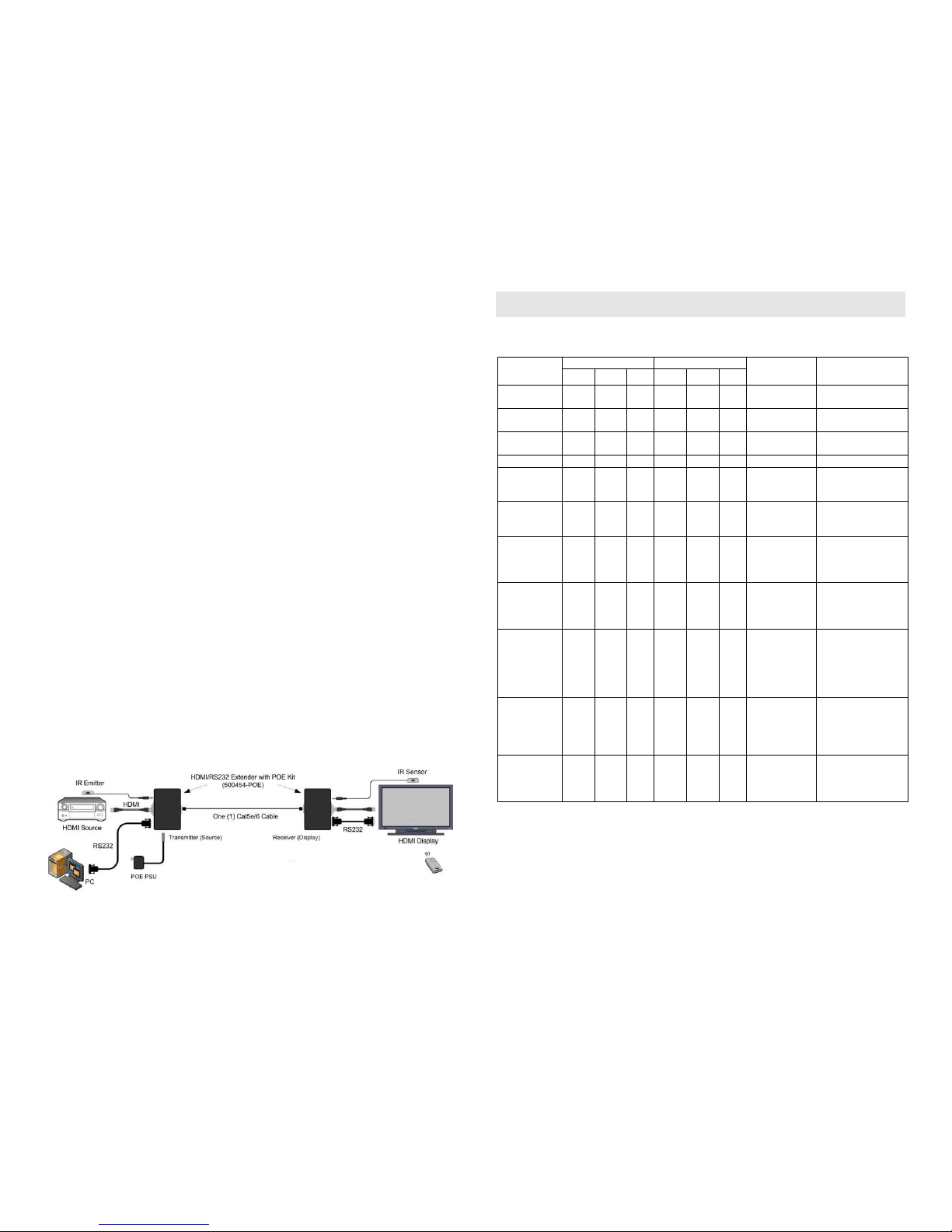
Overview
The HDMI/RS232 Extender Kit, PoE, HDBT, UHD-4K (500454-POE) allows HDMI
equipment to be connected up to 230 ft (70 m) @ 1080p via one (1) Cat 5e/6 unshielded
twisted pair cable in a point-to-point configuration. The 500454-PoE includes one (1)
Transmitter and one (1) Receiver as well as an IR Emitter (500998) and IR Sensor
(500999) for remote control applications. The unit comes with one (1) power supply, as
it only require power on the Transmitter or Receiver side and provides PoE/PoC power
to the opposite end extender. The 500454-POE-RX receivers may be used in
conjunction with MuxLab’s HDMI Matrix Switch. For installation instructions, please
refer to the HDMI Matrix Switch Installation Guide.
Applications
Applications include digital signage, commercial and residential AV systems, classroom
projector systems, boardroom systems, collaborative PC systems, and medical
information systems.
Installation
1. Identify the connectors on the Transmitter and Receiver as indicated on the product
end panels.
2. Verify that the distance between the HDMI Transmitter and Receiver is within
MuxLab specifications (see specifications table).
3. To install the Transmitter:
3a. Connect the Transmitter to the HDMI video source with an HDMI compliant
cable.
3b. Connect one (1) length of Cat 5e/6 (or higher) grade UTP cable to the
RJ45 LINK connector on the Transmitter.
4. To install the Receiver:
4a. Connect the Receiver to the HDMI display equipment with an HDMI compliant
cable.
© MuxLab Inc. 2017
Note: When used with MuxLab’s HDMI Matrix Switch, please consult the Matrix
Switch Installation Guide.
4b. Connect one (1) Cat 5e/6 cable to the RJ45 LINK connector on the Receiver.
5. Connect the 48VDC power supply to either the Transmitter or Receiver first, and
then plug the power supply into an AC power outlet. Only one end (TX or RX end)
needs to be connected to a power supply, which then powers the extender at the
opposite end. If power is present, the green power LED of the Transmitter and the
Receiver will be ON.
Note: Power-up the HDMI / RS232 Extender kit, PoE, HDBT, UHD-4K only after
all connections are made.
6. Power-up the HDMI equipment and verify the image quality.
7. This product support bi-directional IR control. If infrared remote control is needed
to control the Source equipment from the Display, connect the IR Sensor to the
3.5mm Stereo Jack of the receiver and the IR Emitter to the 3.5mm Mono Jack of
the Transmitter.
Note: The IR Sensor can be distinguished from the IR Emitter by looking at the
3.5-mm plug. The IR Sensor has a 3.5mm stereo plug (3 Contacts) and the
IR Emitter has a 3.5mm mono plug (2 Contacts).
8. Position the IR Sensor so that it is aimed toward the hand-held remote control. For
clear IR signal reception, aim the hand-held remote control toward the top of the IR
Sensor enclosure.
9. Position the IR Emitter as close as possible to the source’s IR Sensor (i.e. DVD,
Blu-ray, or media player). For a clear IR signal reception, the IR Emitter may be
affixed to the source’s IR Sensor. The IR Emitter’s signal is transmitted from the
side of the enclosure.
10. If infrared remote control is needed to control the Display equipment from the
Source, connect the IR Emitter to the Receiver’s 3.5mm stereo jack and connect the
IR Sensor to the Transmitter’s 3.5mm mono jack.
11. The 500454-PoE also supports RS232 pass-thru in order to allows a device such as
commercial monitors to be controlled as in digital signage application. Please refer
to the following diagram for the cabling connection.
12. The following diagram shows the final configuration.
Troubleshooting
The following table describes some of the symptoms, probable causes and possible solutions
in regard to the installation of the HDMI/RS232 Extender Kit, PoE, HDBT, UHD-4K:
Symptom
Tx LEDs
Rx LEDs
Probable
Cause
Possible
Solutions
Power
HDMI
RJ45
Power
HDMI
RJ45
No Image
OFF
OFF
OFF
OFF
OFF
OFF
No power
• Check power
connections.
No Image
ON
OFF
OFF
ON
OFF
OFF
UTP Cable
• Check the UTP
cables.
No Image
ON
OFF
ON
ON
OFF
ON
HDMI Cable
• Check the HDMI
Cable.
No Image
ON
ON
ON
ON
ON
ON
Synchronisation
• Check cable length.
Flickering
Image
ON
ON
ON
ON
ON
ON
Synchronisation
• Check cable length.
• Check the HDMI
Cable Quality.
Choppy sound
ON
ON
ON
ON
ON
ON
Synchronisation
• Check cable length.
• Check the HDMI
Cable Quality.
Green or pink
hue
ON
ON
ON
ON
ON
ON
DDC
communication
• Cycle power of the
HDMI Extender.
• Check UTP cables
and replace.
Image flickers
when powering
up nearby
equipment
ON
ON
ON
ON
ON
ON
Interference
• Use STP cables.
IR not
functioning
ON
ON
ON
ON
ON
ON
Remote control
not directed to
the IR Sensor or
IR Emitter not
directed to the
source.
• Make sure the IR
Sensor is directed
towards the remote
and the IR Emitter
to the equipment.
IR not
functioning
ON
ON
ON
ON
ON
ON
Interference
from sunlight,
Fluorescent,
Neon or
Halogen lights.
• Place the IR
equipment away
from the interfering
light.
IR not
functioning
ON
ON
ON
ON
ON
ON
Interference
from RF
radiation from
the TV.
• Place the IR
equipment away
from the RF
radiation.
If you still cannot diagnose the problem, please call MuxLab Customer Technical Support at
877-689-5228 (toll-free in North America) or (+1) 514-905-0588 (International).
 Loading...