

MuxLab 500435 Installation Manual
© MuxLab Inc. 2015 94-000798-A / SE-000798-A
5x1 HDMI / HDBT
Multimedia Presentation
Switch
Installation Guide
500435

5x1 HDMI / HDBT Multimedia Presentation Switch Installation Guide
© MuxLab Inc. 2015 2
SAFETY PRECAUTIONS
To insure the best from the product, please read all instructions carefully before using
the device. Save this manual for further reference.
Follow basic safety precautions to reduce the risk of fire, electrical shock and injury
to persons.
Do not dismantle the housing or modify the module. It may result in electrical shock
or burn.
To prevent fire or s ho ck haz ard, do not expose the unit to r ai n, m ois tur e or i nstall this
product near water. Keep the product away from liquids.
Spillage into the ho usi ng m ay resul t in f ir e, e lec tric al s ho ck, or equipment damage. If
an object or liquid falls or spills on to the housing, unplug the module immediately.
Do not use liquid or aerosol cleaners to clean this unit. Always unplug the power to
the device before cleaning.
Using supplies or parts not meeting the product’s specifications may cause damage,
deterioration or malfunction.
Refer all servicing to qualified service personnel.
Install the device in a place with good ventilation to avoid damage caused by
overheat.
Unplug the power cord when left unused for a long perio d of time.
Do not put any heavy items on the u nit or on extension cable.
Do not remove the housing of the device as you may be exposed you to dangerous
voltage or other hazards.
Do not twist or pull by force ends of the UTP cable. It can cause malfunction.
Information on dis posal of devices: do not burn or mix with gener al hous ehold w aste,
please treat them as normal electrical wastes.
Unpack the equipment carefully and save the original box and packing material for
possible future shipment
NOTICE:
1. Please read this user manual carefully before using this product.
2. The “far-end” item is the device (e.g. display device, 3
rd
party RS232 device etc.)
connected via the 500435.

5x1 HDMI / HDBT Multimedia Presentation Switch Installation Guide
© MuxLab Inc. 2015 3
Contents
1. Introduction ................................................................................................................. 5
1.1 Introduction to the 500435 ................................................................................. 5
1.2 Features ............................................................................................................ 5
1.3 Package Contents ............................................................................................. 5
2. Specification ............................................................................................................... 6
3. Panel Description ........................................................................................................ 8
3.1 The 500435 Front Panel .................................................................................... 8
3.2 The 500435 Rear Panel ................................................................................... 10
4. System Connection ................................................................................................... 11
4.1 Safety Precautions .......................................................................................... 11
4.2 System Diagram .............................................................................................. 11
4.3 Connection Procedure ..................................................................................... 12
4.4 Connection of Microphone ............................................................................... 12
4.5 Application ....................................................................................................... 14
5. Operations ................................................................................................................ 15
5.1 Operations of Front Panel Buttons .................................................................. 15
5.1.1 Adjusting Resolution .............................................................................. 15
5.1.2 Switching Operations ............................................................................. 15
5.1.3 Adjusting the Volume ............................................................................. 16
5.1.4 On-Screen Display (OSD) Menu ........................................................... 17
5.1.5 Software update: ................................................................................... 17
5.2 Operat ions of IR .............................................................................................. 18
5.2.1 IR Remote ............................................................................................. 18
5.2.2 IR Operations ........................................................................................ 19
5.3 Operat ions of CEC Function ............................................................................ 20
5.4 Operations of RS232 Control ........................................................................... 21
5.4.1 RS232 Communic ation Commands ...................................................... 21
5.4.2 Control the 500435 or 3rd Party Device locally...................................... 29
5.4.3 Control the 500435 locally or remotely .................................................. 30
5.5 Operations in OSD Menu................................................................................. 31
5.5.1 Option .................................................................................................... 31

5x1 HDMI / HDBT Multimedia Presentation Switch Installation Guide
© MuxLab Inc. 2015 4
5.5.2 Picture ................................................................................................... 32
5.5.3 Sound .................................................................................................... 33
5.5.4 Setup ..................................................................................................... 33
5.6 Instructions of VGA Converting Cable ............................................................. 34
6. Panel Drawing .......................................................................................................... 36
7. Troubleshooting & Maintenance ............................................................................... 37
Regulatory Compliance ................................................................................................ 40

5x1 HDMI / HDBT Multimedia Presentation Switch Installation Guide
© MuxLab Inc. 2015 5
1. Introduction
1.1 Introduction to the 500435
The 500435 is a compact scaler switcher with 5 video inputs (3 HDMI, 2 VGA) and 6
audio inputs (3 HDMI audio & 2 VGA audio switched following the video; 1 MIC audio
input). The VGA input supports VGA, Component Video (YPbPr) and Composite Video.
The 500435 scales & switches any video signal to HDMI output and HDBa seT output for
a transmission up to 70 m over a Cat5e/6 with PoC support.
With 1 IR Sensor, 5 IR Emitters and 1 RS232 ports, bidirectional IR & RS232 signals
can be transmitted simultaneously between the 500435 and the HDMI Extender
PoC/PoE Receiver.
1.2 Features
• Supports video source auto-switching function
• Bi-directional IR & RS232 control
• Supports HDMI, VGA, Composite Video, and Component Video (YPbPr)
• Output resolutions selectable (1920x1200, 1920x1080, 1600x1200, 1360x768,
1280x800, 1280x720, 1024x768)
• Supports CEC, with commands to enable/disable this function
• Compliant with HDCP
• Supports online software upgrading
• MIC port supports b ala nce/ un balan ce si gnal , and suppresses the external
noise effectively
• 48V phantom power option to support condenser microphone
• 3-level MIC input, supports condenser microphone, dynamic microphone and
wireless microphone
• Controllable via button, IR & RS232
• Powerful OSD function
1.3 Package Contents
• One (1) 5x1 HDMI / HDBT Multimedia Presentation Switch
• Two (2) Mounting wall brackets
• Four (4) Black screws
• Seven (7) Captive screw connectors
• One (1) IR Sensor (with carrier wave)
• One (1) IR Emitter
• Two (2) VGA to Component Video (YPbPr) or Composite Video cables

5x1 HDMI / HDBT Multimedia Presentation Switch Installation Guide
© MuxLab Inc. 2015 6
• Two (2) RS232 cable
• Four (4) Plastic cushions with black screws
• One (1) IR remote (Two AAA batteries needed, not included)
• One (1) 12VDC, 2A Power Adapter with interchangeable blades
• One (1) User Manual
Notes: Please confirm if the product and the accessories are all included, if not,
please contact your dealer.
2. Specification
Environment
HDMI 1.3
Devices
DVD, plasma, pro ject or s, mo nit or s, T V, PC, laptops, serv ers
supporting HDMI
Transmission
Tr ans pa rent to the user
Video Bandwidth
HDMI: 4. 96 G b ps
Composite Video:150MHz
Component Video (YPbPr): 170MHz
VGA: 375MHz
Maximum P ix el
Clock
165 MHz
Video Impedance
75 Ω
Video Resolution
1920x1200, 1920x1080, 1600x1200, 1360x768, 1280x800,
1280x720, 1024x768
Audio Frequency
Response
20Hz to 20KHz
Audio Impedanc e
Input: >10kΩ
Output: 70 Ω
Stereo Chann el
Separation
>80dB @1KHz
Signals
HDMI 1.3 proto col an d HDC P

5x1 HDMI / HDBT Multimedia Presentation Switch Installation Guide
© MuxLab Inc. 2015 7
Connectors
Four (4) HDMI re cept acl es; Thr ee (3 ) Inp ut s & One (1) Output.
Two (2) VGA HD-15 recepta c le s (Inputs).
One (1) RJ45 for HDBT (output).
Six (6) 3-pin termina l bloc k (3.81 mm) for Aud io; Five (5) Inputs
& one (1) Output.
One (1) 3-pin terminal block (3.81 mm) f or th e mic ro phon e.
Five (5) IR Emitter 3.5mm Mono jacks.
One (1) IR Sen sor 3. 5mm S tere o jac k.
One (1) 3-pin terminal block (3.81 mm) f or R S 2 32 .
One (1) 2.1mm barrel jack for Power.
One (1) USB Type A.
Note: HDMI cables not included.
Maximum D is t an c e
Based on a maximum
length of 6.6 ft. (2 m) of
HDMI cable per end.
Cat 5e/6: 230 ft (70 m) up t o 1080 p
Note: When installed in an electrically noisy environment, an STP
cable must be used. Also, cross-connection reduces the
effective distance depending o n the grade of twisted cable u sed.
Cable
One (1) Ca t 5e/6 or better tw isted pair ca bl e required
Compatible
Receiver
500451-R X (No Se ri al Po rt, No PoE )
500454-RX (With Serial Port, No PoE)
500454-POE-RX ( With Serial Port and PoE)
Power Supply
One (1) 110-240V/1 2VDC pow er su pply wit h inte rc han geab le
blades
Power
Consumption
8 Watts for the 500435 alone.
16 Watts when th e 500435 provides PoE power t o the HDMI
Extender Receivers.
Temperature Operatin g: 0° to 40°C Storage: -20° to 85 °C
Humidity : Up to 9 5% non-condensing
Enclosure
Metal
Dimensions
8.66” x 1.73” x 5.83” (220 x 44 x 148 mm)
Weight
0.65 kg
Compliance
Regulatory: FCC, CE, RoHS
Warranty
2 years
Order Information
500435 5x1 HDMI / HDBT Multimedia Presentation Switch
5x1 HDMI / HDBT Multimedia Presentation Switch Installation Guide
© MuxLab Inc. 2015 8
3. Panel Description
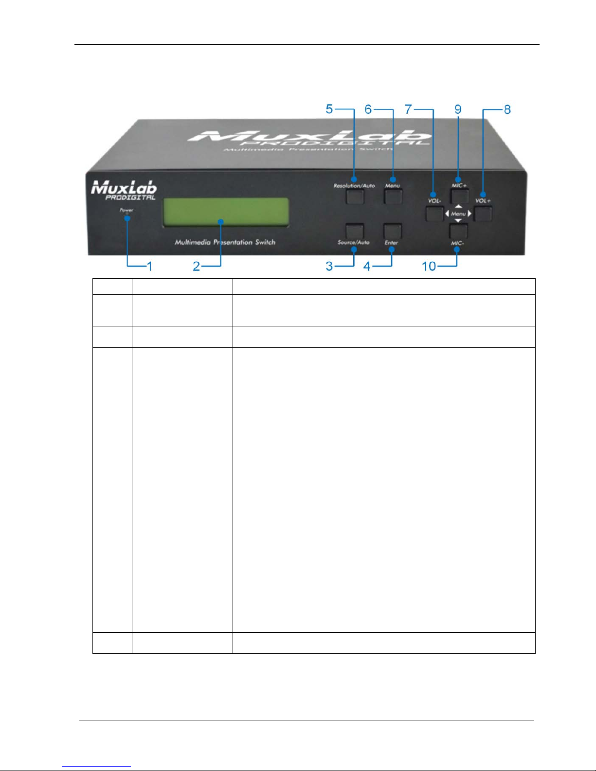
3.1 The 500435 Front Panel
No.
Name
Description
1
Power indicator
Turns on red when power is on, turns green in standby
mode.
2 LCD screen
Shows real-time system working status.
3
Source/Auto
• Used as video source selection button, press to
select one source, press again to select next source,
switching circularly between HDMI1, HDMI2, HDMI3,
VGA1 and VGA2. The LCD screen will show the
name of selected source.
• Used as switching mode selection button, press and
hold for 7 seconds or more to enter the
Auto-switching mode, press and hold for 7 seconds
or more again to enter the Manual-switching mode.
Note: When setting any VGA port to AV or YPbPr in
Manual-switching mode, the system will not be able
detect video and to enter the Auto-switching mode.
While in Auto-switching mode, setting any VGA port
to AV o r YPbPr will automatically revert to
Manual-switching mode, and the LCD screen and
RS232 control software will prompt “Not supported!”.
4
Enter
Confirm selection in menu.

5x1 HDMI / HDBT Multimedia Presentation Switch Installation Guide
© MuxLab Inc. 2015 9
No.
Name
Description
5
Resolution/Auto
• Used as output resolution manual switching button,
select among 1920x1200, 1920x1080, 1600x1200,
1360x768, 1280x800, 1280x720, 1024x768.
• Used as output resolution switching mode selection
button, press and hold for 7 seconds or more to
enter in Auto-switching mode, press and hold for 7
seconds or more ag ain to enter the
Manual-switching mode.
6 Menu
• Used as menu button, press to enter the OSD menu.
• Used as softw ar e updatin g button, press and hold for
7 seconds or more to enter the software updating
procedure.
7 VOL-
• Used as volume down button.
• Used as direction button NEXT in menus.
8
MIC+
• Used as MIC volume up button.
• Used as direction button MOVE UP in menus.
9 VOL+
• Used as volume up button.
• Used as direction button PREVIOUS in menus.
10
MIC-
• Used as MIC volume down button.
• Used as direction button MOVE DOWN in menus.
5x1 HDMI / HDBT Multimedia Presentation Switch Installation Guide
© MuxLab Inc. 2015 10
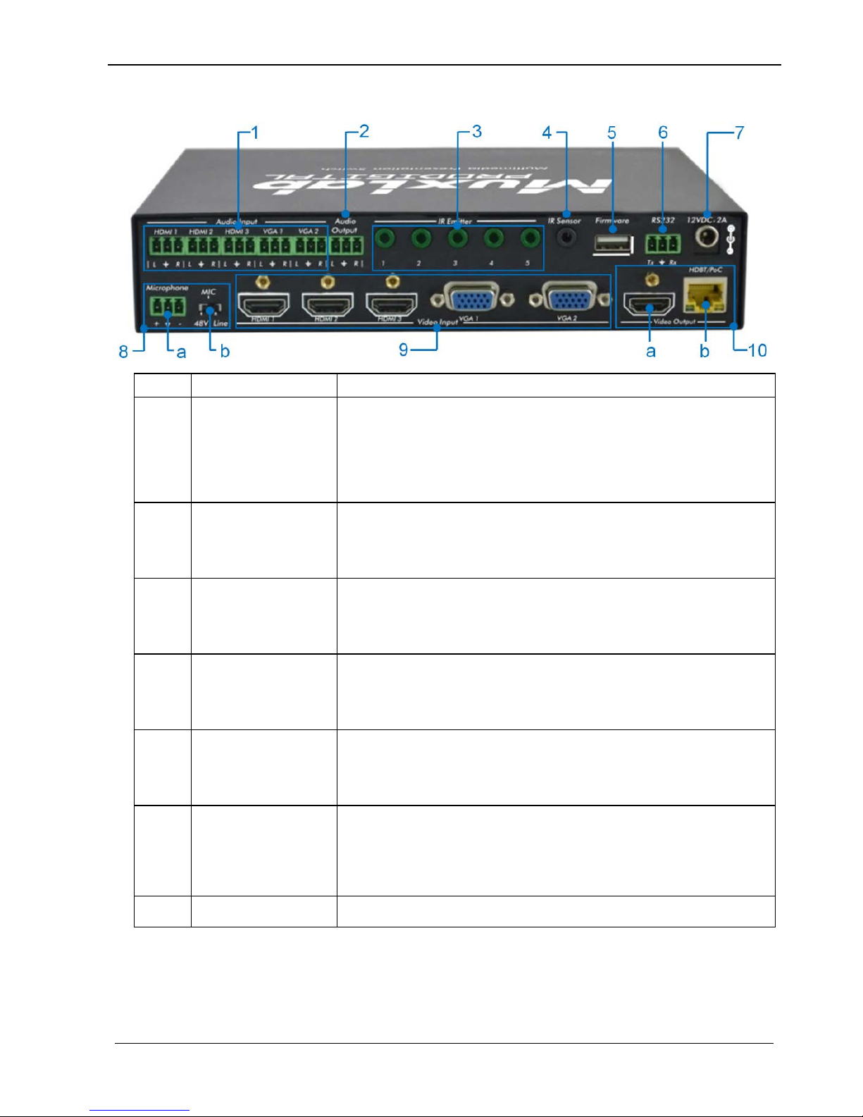
3.2 The 500435 Rear Panel
No.
Name
Description
1 Audio Input
Includes 3 HDMI audio & 2 VGA audio inputs
User can choose embedded HDMI audio or external
input audio for HDMI audio input. It is contr oll abl e by
RS232 commands.
2 Audio Output Audio output port, the audio comes from the input audio
corresponding to the selected video source and mixed
with MIC audio.
3
IR Emitter
Five IR Emitter ports connect with IR emitters to control
local source devices or the 500435 from remote,
switched along with the corresponding video sour ce.
4 IR Sensor Connects with IR Sensor (with carrier wave only), to
receive IR signal sent by the IR remote or remote
controller of other input/o utput device.
5
Firmware
This USB port connects with USB flash disk or other
storage device loaded with the firmware u pdate file, to
update the system firmware.
6
RS232
This Serial control port, 3-pin term inal block connector,
connects to a control device (such as a computer) to
control the 500435
or other devices connected with
HDMI Extender Receivers.
7 12VDC, 2A
Power port, connects with 12V DC power adapter.
5x1 HDMI / HDBT Multimedia Presentation Switch Installation Guide
© MuxLab Inc. 2015 11
No.
Name
Description
8
Microphone
a) Microphone port: Connects to a microphone
b) Switch that Includes 3 levels: (1) 48V phantom pow er
mode (connect with condenser microphone),
(2) MIC mode (connect with dynamic microphone)
and (3) LINE mode (connect with wireless
microphone or line audio).
9 Video Input Video input ports, include 3 HDMI inputs & 2 VGA
inputs.
VGA ports support YPbPr, Composite video and VGA
format. Factory default i s VGA format.
10
Video Output
a) HDMI local output
b) HDBaseT output, s upport PoC/PoE.
Both HDMI and HDBT ports share the same audio
signal. The audio s ignal is mixed with MIC audio and
HDMI embedded audio (output audio). If the HDMI
embedded audio output is disabled, then there w ill be no
audio present on thes e ports.
4. System Connection
4.1 Safety Precautions
1) System should be installed in a clean environment with temperature and humidity
within the operating levels.
2) All devices should be connected before power on.
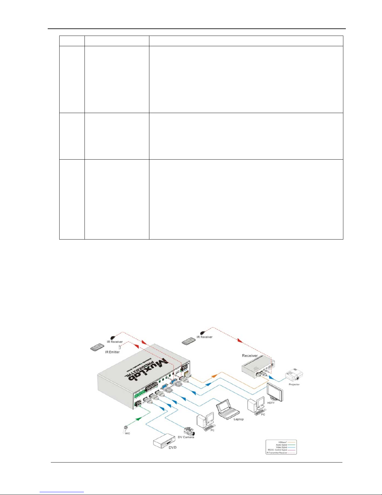
4.2 System Diagram

5x1 HDMI / HDBT Multimedia Presentation Switch Installation Guide
© MuxLab Inc. 2015 12
4.3 Connection Procedure
a) Connect HDMI source devices (e.g. Blue-ray DVD) to HDMI input ports of the
500435 with HDMI cabl es. Connect VGA source devices (e.g. PC) to VGA input
ports of the 500435 with VGA cables.
b) C onnec t audio sou rce s to corresponding Audio Input ports on the 500435 with
audio cable. The audio of HDMI can be selected from the embedded audio or from
the external audio.
c) Connect an HDMI display device to the HDMI output port of the 500435 with HDMI
cable.
d) Connect HDMI Extender PoC/PoE Receiver to the HDBas eT output port of the
500435 with a twi sted pair Cat5e/6 cable.
e) Connect speakers, headphones or an amplifier to the Audio Output port of the
500435.
f) Connect control device (e.g. PC) to the RS232 port of the 500435; or to the HDMI
Extender PoC/PoE Receiver (with bidirectional RS232 control).
g) Both the 500435 and the HDMI Extender PoC/PoE Receiver have IR sensors and
emitters. When one end is connected with IR sensor, the other end should be
connected with an IR emitter.
•
For example: When an “IR Sensor” of the 500435 connects to an IR Sensor,
the IR Emitter must be connected to IR Emitter port of HDMI Extender
PoC/PoE Receiver.
•
The IR signal can be transmitted in both directions simultane ously between the
500435 and the HDMI Extender PoC/PoE Receiver.
h) Select MIC level and connect the right microphone to Microphone input port. MIC
audio will be transmitted to Audio Output port and mixed with the audio source.
i) Connect 12V DC power to the power port. The HDMI Extender PoC/PoE Receiver
will get power from the 500435 via PoC/PoE function.
4.4 Connection of Microphone
The 500435 provides wit h 3-level microphone input port, to accommodate different
microphone input modes, including 48V phantom power mode, MIC mode & LINE mode.
48V phantom power input:
The 48V phantom power input has a good frequency characteristic, high input
impedance and high sensitivity.
When switching to “48V”, the MIC input will provide a 48V phantom power. This is only
used for condenser microphones.
 Loading...