

MuxLab 500415 Installation Manual
P/N: 94-000671-A SE-000671-A
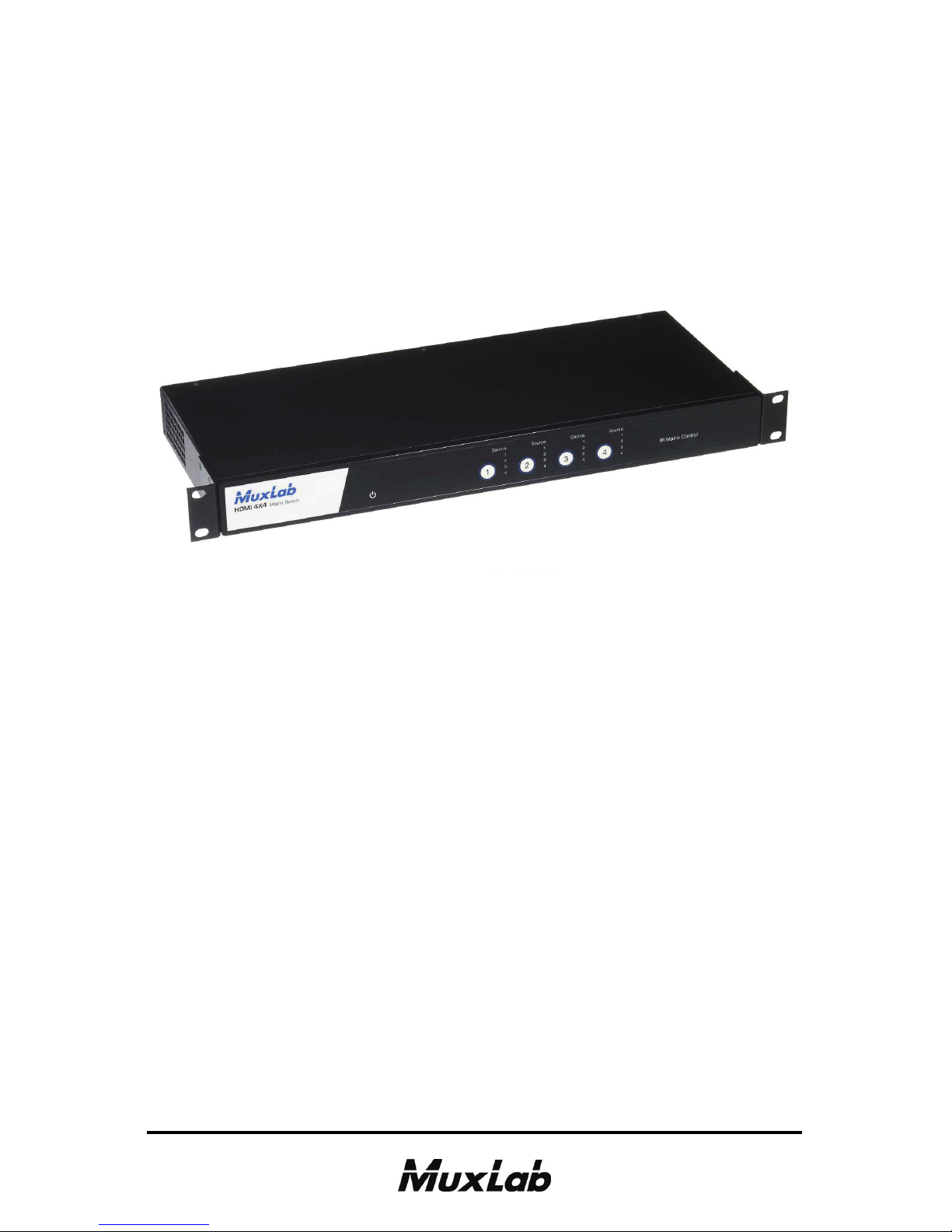
HDMI 4x4 Matrix Switch
500415
Installation Guide

© MuxLab Inc. HDMI 4x4 Matrix Switch Installation Guide
Pag
e 2
Copyright Notice:
Copyright © 2011 MuxLab Inc. All rights reserved.
Copyright © 2009 Real Time Engineers Ltd.
This product uses an unmodified version of FreeRTOS V6.0.0.
Source code available at www.freertos.com
Printed in Canada. No part of this publication may be reproduced,
stored in a retrieval system, or transmitted in any form or by any
means, electronic, mechanical, photocopying, recording or
otherwise without prior written permission of the author.
Trademarks:
MuxLab is a registered trademark of MuxLab Inc.

© MuxLab Inc. HDMI 4x4 Matrix Switch Installation Guide
Pag
e 3
Table of Contents
1. Overview .........................................................................4
1.1. Description ..............................................................4
1.2. Features ...................................................................5
2. Technical Specifications ................................................6
3. Installation Procedure ...................................................7
3.1. Parts List .................................................................7
3.2. Product Overview ...................................................8
3.3. Pre-Installation Checklist ...................................... 10
3.4. Physical Installation .............................................. 11
3.5. Installation Procedure............................................12
3.6. Port Control Operation..........................................15
3.7. Driver Setup ..........................................................17
3.8. MuxLab Control Center Software......................... 20
3.9. Ethernet Web Interface .........................................25
3.10. Cascadability......................................................... 29
4. Troubleshooting ...........................................................32
5. Appendix.......................................................................34
A. ASCII Command Set.............................................34
B. Serial Port and LAN Setup.................................... 39
C. Infrared Remote Control Codes ............................ 41
6. Product Warranty Policy ............................................42
© MuxLab Inc. HDMI 4x4 Matrix Switch Installation Guide
Pag
e 4
1.
Overview
1.1. Description
The MuxLab 500415 HDMI 4x4 Matrix Switch allows
four (4) HDMI sources to be switched/distributed up to
four (4) local displays and up to four (4) remote displays
via unshielded twisted pair (UTP) or shielded twisted
pair (STP) cables for cost-efficient connectivity. Remote
HDMI equipment can be connected up to 150 feet (46
meters) @ 1080p Deep Color via two (2) Cat 6 UTP
cables. The HDMI 4x4 Matrix Switch works in
conjunction with MuxLab’s HDMI Receivers (500407
or 500417).
Applications include commercial and residential AV
systems, classroom projector systems, digital signage,
boardroom systems, multi-room systems, classroom
training, retail systems, collaborative PC systems, and
medical information systems.

© MuxLab Inc. HDMI 4x4 Matrix Switch Installation Guide
Pag
e 5
1.2. Features
UTP/STP modular RJ45 jacks on four (4) outputs.
HDMI input and HDMI local output.
IR support for remote control of all four (4) HDMI
sources.
Support for 1080p Deep Color up to 150 ft (46 m) via
Cat 6 UTP cables.
Seamless integration with MuxLab’s HDMI Receivers
(500407 or 500417).
© MuxLab Inc. HDMI 4x4 Matrix Switch Installation Guide
Pag
e 6
2.
Technical Specifications
Environment
HDMI 1.3A
Devices
LCD and Plasma TVs, DVD and Blu-Ray players, monitors, projectors, PCs, laptops,
home theatre systems, home theater PCs, game consoles, servers that support HDMI.
Transmission
Transparent to the user
Bandwidth
Video: 225 MHz
Signals
HDMI 1.3a protocol
Connectors
HDMI Cables not included.
Source Input: Four (4) HDMI receptacles
Local Output: Four (4) HDMI receptacles
Distributed Output: Four (4) UTP/STP outputs via eight (8) RJ45S connectors for
Cat 5e/6 UTP/STP cabling
Maximum Distance
HDMI Switch to Display
Based upon a maximum
length of 6.6 ft (2 m) of HDMI
cable per end.
Cat 5e Cat 6
480i/p 300 ft (91 m) 300 ft (91 m)
720p, 1080i 300 ft (91 m) 300 ft (91 m)
1080p 150 ft (46 m) 200 ft (61 m)
1080p Deep Color 90 ft (27 m) 150 ft (46 m)
NOTE: STP cables must be used in an electrically noisy environment. Also, cross-connection
reduces the effective distance depending on the grade of twisted cable used.
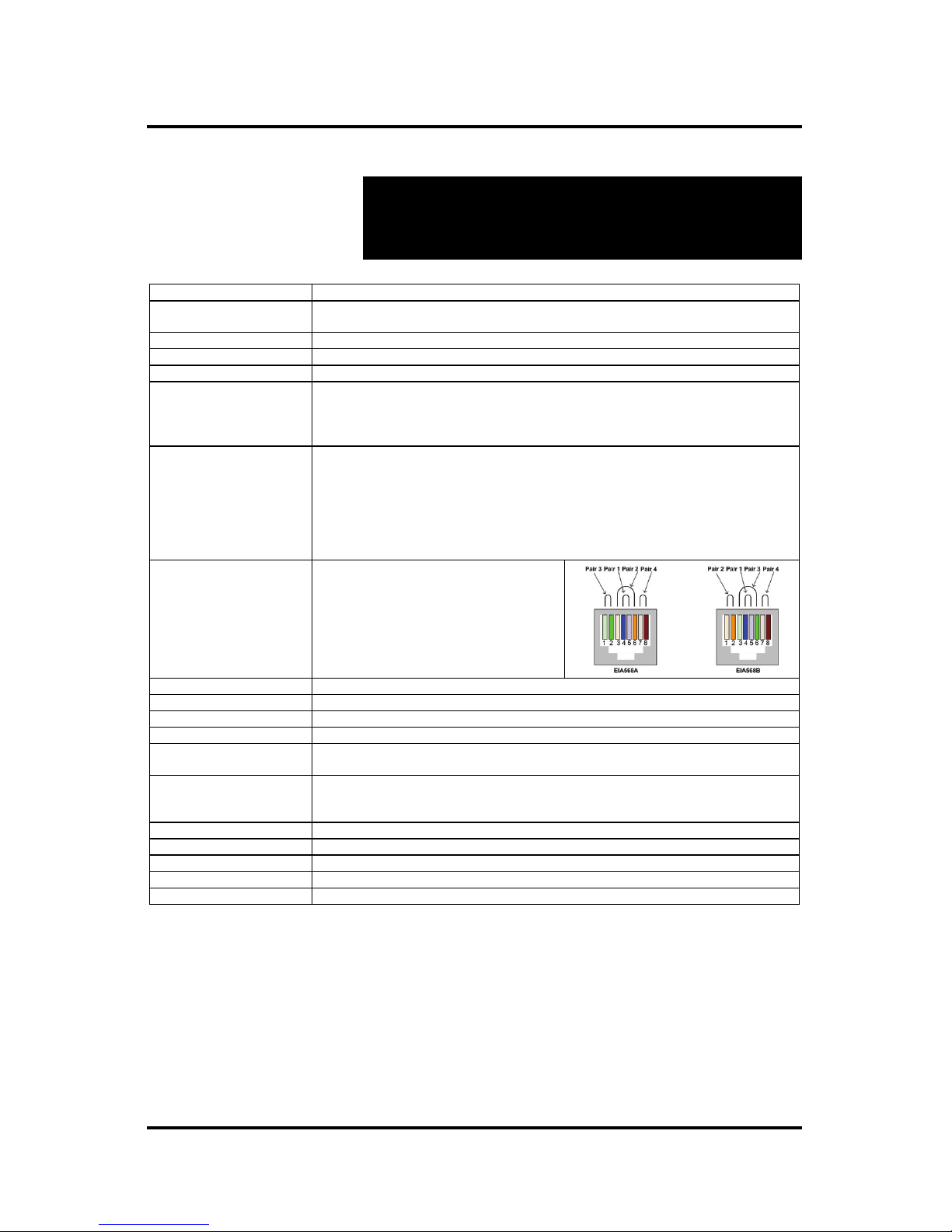
RJ45 Pin Configuration
Reverse Polarity Sensitive
Use EIA/TIA 568A or 568B
straight-through wiring
RJ45 A (HDMI A) RJ45 B (HDMI B)
Pin 1 (R) Pin 2 (T) Pin 1 (R) Pin 2 (T)
Pin 3 (R) Pin 6 (T) Pin 3 (R) Pin 6 (T)
Pin 4 (R) Pin 5 (T) Pin 4 (R) Pin 5 (T)
Pin 7 (R) Pin 8 (T) Pin 7 (R) Pin 8 (T)
Cable
Two (2) Cat 5e/6 UTP/STP cables (or better) required per port
Power Supply
One (1) 110-240V/12VDC, 2.5A power supply with three interchangeable blades
Compatible Receivers
500407, 500417
Power Consumption
30 Watts
LED Diagnostics
Power (Blue)
Interconnection Matrix (Green)
Temperature
Operating: 0ºC to 40ºC
Storage: -20ºC to 85ºC
Humidity: Up to 95% non-condensing
Dimensions
1U Rack Mountable: 19.00” x 7.50” x 1.75” (48.26 cm x 19.05 cm x 4.45 cm)
Weight
4.0 lb (1.8 kg)
Regulatory
FCC, CE-EMC Directive 89/336/EE, RoHS, WEEE
Warranty
Two (2) years
Order Information
500415: HDMI 4x4 Matrix Switch (includes four [4] IR Emitters)

© MuxLab Inc. HDMI 4x4 Matrix Switch Installation Guide
Pag
e 7
3.
Installation Procedure
3.1. Parts List
The HDMI 4x4 Matrix Switch (500415) comes with the
following parts:
Base Unit
Four (4) IR Emitters
One (1) 110-240V/12VDC, 2.5A Power Supply with
three interchangeable blades
One (1) USB Type A – Type B Cable
One (1) USB flash drive with Port Control Software
Four (4) rubber feet for set-top operation
One (1) infrared remote
Installation Guide
Please verify that all parts are present before proceeding.
© MuxLab Inc. HDMI 4x4 Matrix Switch Installation Guide
Pag
e 8
3.2. Product Overview
The external connections and connection indicators of
the HDMI 4x4 Matrix Switch are detailed in Figure 1
and Figure 2. Please familiarize yourself with them
before installing the unit.
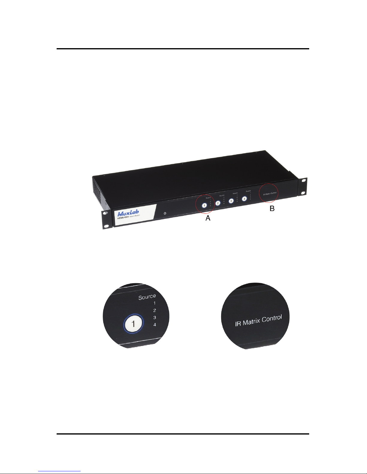
Figure 1: Front Panel of Matrix Switch
Detail A Detail B
Display Push Button IR Matrix Control LED
& HDMI Source LEDs
© MuxLab Inc. HDMI 4x4 Matrix Switch Installation Guide
Pag
e 9
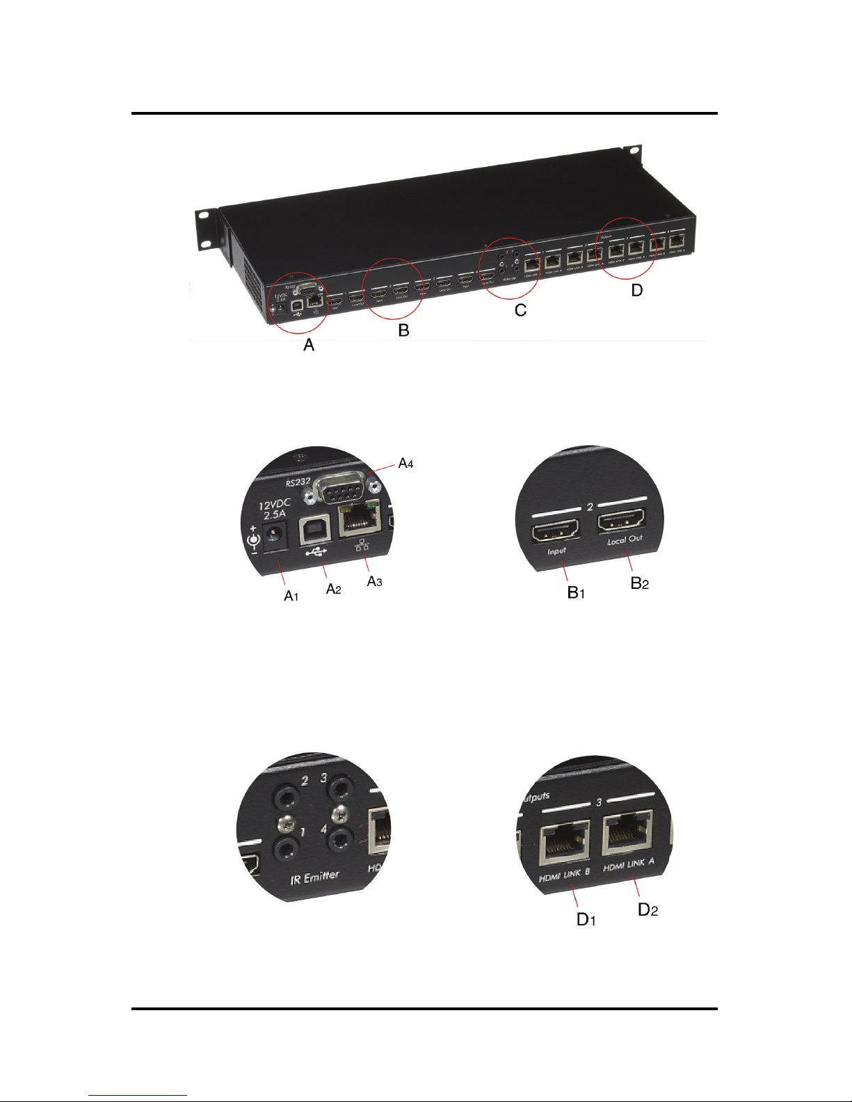
Figure 2: Back Panel of Matrix Switch
Detail A Detail B
A1 = Power Supply Port B1 = HDMI Input
A
2
= USB Port B2 = HDMI Local Out
A
3
= Ethernet Port
A
4
= RS232 Port
Detail C Detail D
IR Emitter Jacks D1 = RJ45 Output Jack B
D2 = RJ45 Output Jack A

© MuxLab Inc. HDMI 4x4 Matrix Switch Installation Guide
Pag
e 10
3.3. Pre-Installation Checklist
The HDMI 4x4 Matrix Switch provides a centralized
HDMI switching center via copper UTP/STP cables.
1. The HDMI 4x4 Matrix Switch is used in conjunction
with MuxLab’s HDMI Receivers (500407 or
500417).
2. The HDMI 4x4 Matrix Switch is typically installed
in a remote telecom room and is connected to the
HDMI video source and display devices via Cat 5e/6
UTP/STP cables. A MuxLab HDMI Receiver is
installed at each HDMI display to support the
connection to the Matrix Switch via Cat 5e/6 cables.
© MuxLab Inc. HDMI 4x4 Matrix Switch Installation Guide
Pag
e 11
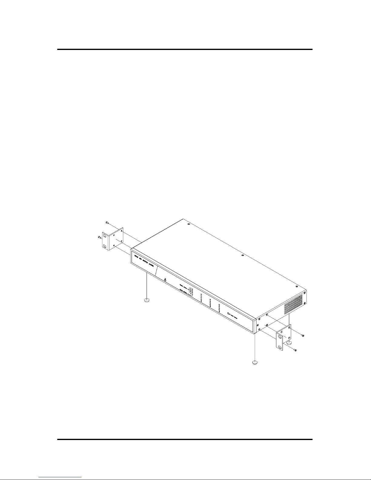
3.4. Physical Installation
MuxLab’s HDMI 4x4 Matrix Switch comes with
mounting brackets for standard 19” rack mounting.
Select the final destination for the product and install the
unit using standard rack-mount screws.
For set-top installation, the L-brackets on the side of the
unit may be removed and the included rubber feet
placed on the bottom of the unit. When removing the Lbrackets, be careful to keep and reinstall the four screws
on each side of the unit.
Figure 3: Procedure for Set-Top Installation

© MuxLab Inc. HDMI 4x4 Matrix Switch Installation Guide
Pag
e 12
3.5. Installation Procedure
In order to install the product, please follow the steps
below:
1. Place the HDMI 4x4 Matrix Switch in its final
location.
2. Ensure that the power is turned off on the HDMI
source and displays.
3. In order to distribute the HDMI, one (1) HDMI
Receiver (500407 or 500417) must be connected at
each HDMI display. To install the Receivers,
complete Steps 4, 5, and 6.
4. Identify the pin configuration of the Receivers. Two
(2) Cat 5e/6 UTP/STP cables are required for each
HDMI connection. The pin configuration follows the
EIA/TIA 568A/B standard. The HDMI Receiver is
reverse-polarity sensitive. Please ensure that the
wiring is straight-through (Ring to Ring, Tip to Tip),
and that the two HDMI twisted pair links are not
crossed.
5. Using an HDMI cable (not supplied), plug each
HDMI source to an HDMI input of the Matrix
Switch.
6. Using an HDMI cable (not supplied), connect an
HDMI Receiver (500407 or 500417) to each HDMI
display.
7. Complete the connection between the Matrix Switch
and each HDMI display using standard straight-thru

© MuxLab Inc. HDMI 4x4 Matrix Switch Installation Guide
Pag
e 13
Cat 5e/6 UTP/STP cables and connecting hardware,
terminated on RJ45 plugs at both ends. Ensure that
there are no split pairs or taps.
8. Optional: Local televisions may be connected using
HDMI cables (not supplied).
9. Power up the Receivers and HDMI equipment first.
10. Connect the external 12VDC power supply to the
Matrix Switch and plug the power supply into an AC
power outlet. If power is present, the blue power
LED will be ON.
11. Ensure that the source and appropriate display LEDs
are ON. Images should appear on the displays within
10 seconds. Check the image quality and refer to the
troubleshooting table in Section 4 if image quality is
unsatisfactory.
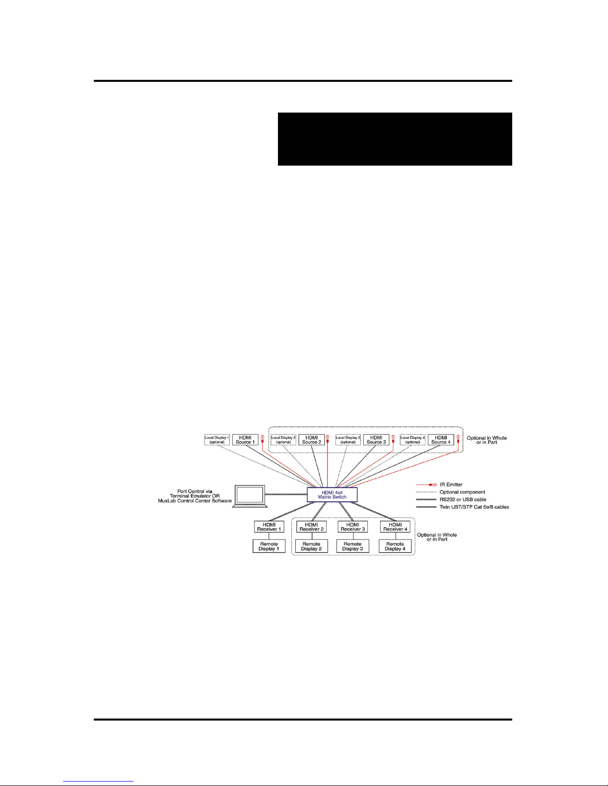
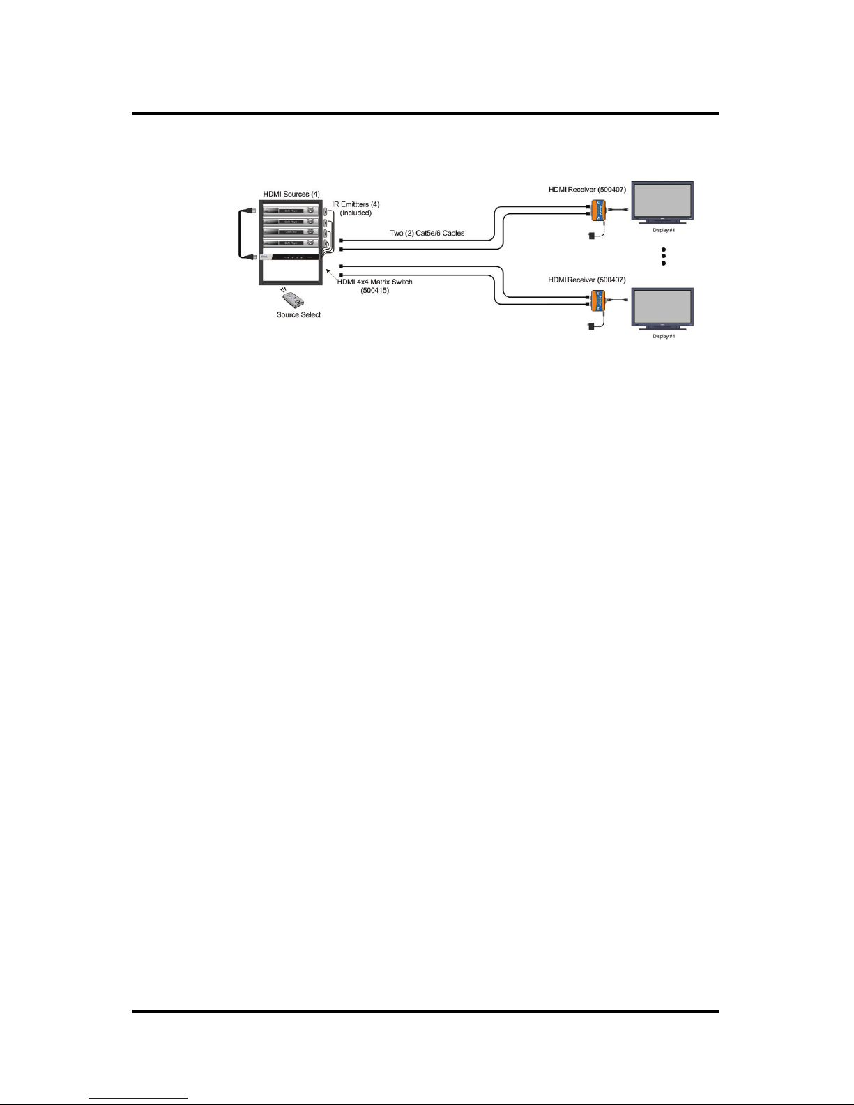
12. Figures 4 and 5 show some typical configurations:
Figure 4: Typical Configuration (I)
© MuxLab Inc. HDMI 4x4 Matrix Switch Installation Guide
Pag
e 14
Figure 5: Typical Configuration (II)
Please note that Figure 5 is for users who do not require
control of the Matrix Switch from a remote location. In
such a case, MuxLab’s HDMI Receiver (500407) may
be used.
The IR Emitters included with the Matrix Switch are
used to control HDMI sources. Simply insert the plug of
an IR Emitter into any one of the 4 “IR Emitter” jacks
located on the back panel of the Matrix Switch. The
number of the jack (1, 2, 3, or 4) into which a specific
Emitter is plugged determines which HDMI Source that
Emitter will control. For example, an IR Emitter
plugged into IR Emitter jack 3 will control HDMI
Source 3.
For more information on installing and using IR
Emitters, please refer to MuxLab’s IR Emitter Quick
Installation Guide.
 Loading...