

MuxLab 500210 Installation Manual
Audio 8x8 Matrix Switch
500210
Installation Guide
P/N: 94-000759-A

© MuxLab Inc. Audio 8x8 Matrix Switch Installation Guide
Copyright Notice:
Copyright © 2014 MuxLab Inc. All rights reserved.
Copyright © 2009 Real Time Engineers Ltd.
This product uses an unmodified version of FreeRTOS V6.0.0. The source code is available at
www.freertos.com.
Printed in Canada. No part of this publication may be reproduced, stored in a retrieval system, or
transmitted in any form or by any means, electronic, mechanical, photocopying, recording or
otherwise without prior written permission of the author.
Trademarks:
MuxLab is a registered trademark of MuxLab Inc.
Page 2

© MuxLab Inc. Audio 8x8 Matrix Switch Installation Guide
Table of Contents
1. Overview .....................................................................................................................................4
1.1. Description ............................................................................................................................... 4
1.2. Features .................................................................................................................................... 5
2. Technical Specifications ............................................................................................................6
3. Installation Procedure ...............................................................................................................7
3.1. Parts List .................................................................................................................................. 7
3.2. Product Overview .................................................................................................................... 8
3.3. Pre-Installation Checklist ......................................................................................................... 9
3.4. Physical Installation ............................................................................................................... 10
3.5. Installation Procedure ............................................................................................................ 11
3.6. Manual Control of Matrix Switch .......................................................................................... 13
3.7. Remote Control of Matrix Switch .......................................................................................... 15
3.8. Cascadability .......................................................................................................................... 16
3.9. Port Control Operation ........................................................................................................... 17
3.10. USB Driver Setup .................................................................................................................. 18
3.11. Ethernet Web Interface .......................................................................................................... 21
4. Troubleshooting .......................................................................................................................30
5. Appendix ...................................................................................................................................31
A. ASCII Command Set ............................................................................................................. 31
B. Serial/USB Port Commands ................................................................................................... 32
C. IP Control Commands ............................................................................................................ 41
D. Infrared Remote Control Codes ............................................................................................. 45
6. Product Warranty Policy ........................................................................................................46
Page 3
© MuxLab Inc. Audio 8x8 Matrix Switch Installation Guide
1.
1.1.
Overview
Description
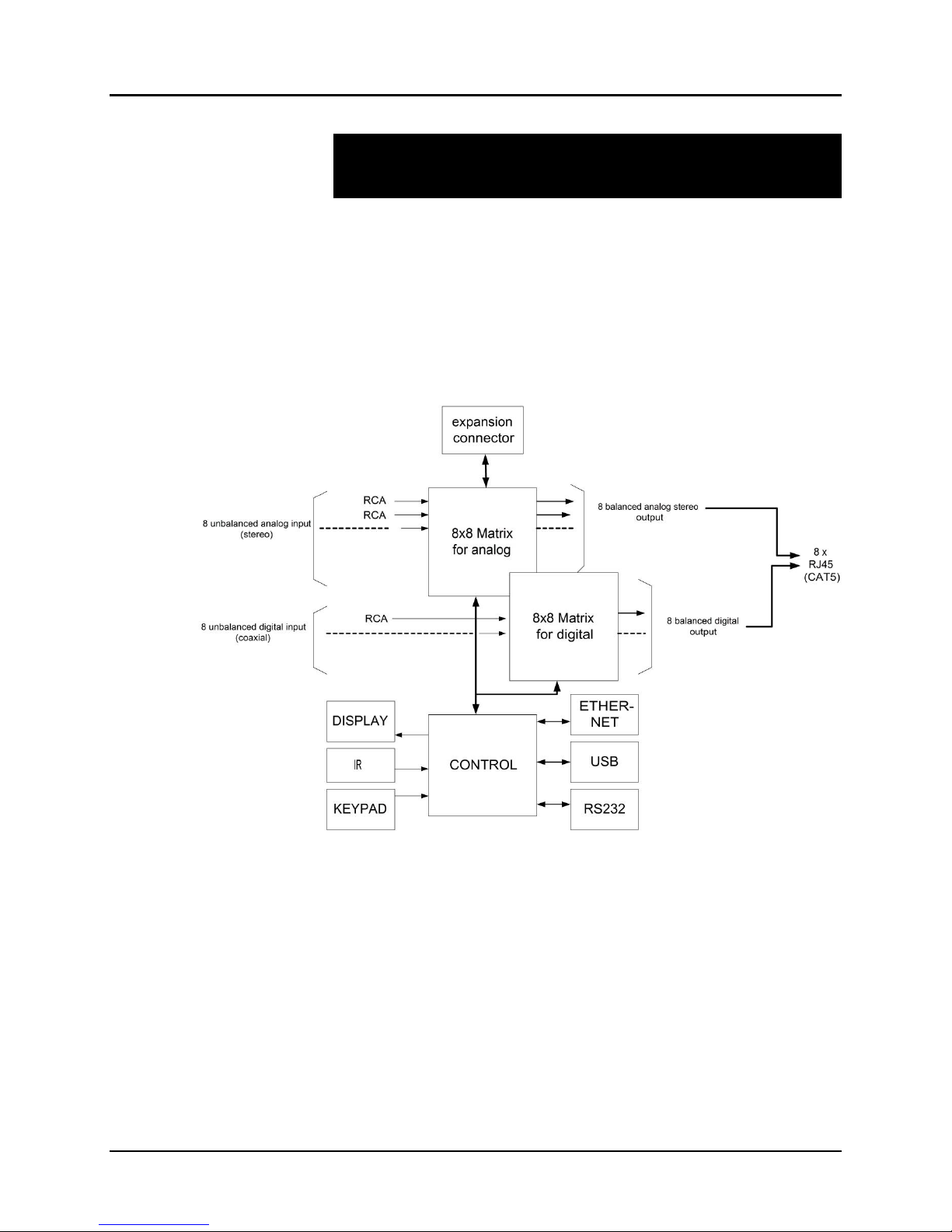
MuxLab’s Audio 8x8 Matrix Switch (500210), allows 8 analog or digital sources to be
switched/distributed to up to 8 remote receivers via unshielded twisted pair (UTP) for
cost-efficient connectivity. Remote receivers can be connected up to via MuxLab
analog balun (500028) or digital balun (500020). An expansion port is available to add
8 or 16 analog ports only.
Applications include commercial and residential audio systems, boardroom systems,
multi-room systems, classroom training, retail systems, and medical information
systems.
Figure 1: Block Diagram
Page 4

© MuxLab Inc. Audio 8x8 Matrix Switch Installation Guide
1.2.
Features
Single modular RJ45 jacks.
UTP extension for analog (stereo channel) and digital (SPDIF) via eight RJ45 jacks
and Cat 5e/6 UTP cables.
Seamless integration with MuxLab analog balun (500028) or digital balun (500020).
Web interface.
RS232 and USB CDC control.
Firmware is field upgradable.
Touch pad on front panel for manual control.
Device control over HTTP protocol.
1U rackmount unit.
Page 5

© MuxLab Inc. Audio 8x8 Matrix Switch Installation Guide
2.
8x8 Audio Matrix Switch
Environment
Stereo, Analog, SPDIF, Digital
Devices
DVD and Blu-Ray players, home theatre systems, home theater PCs, game consoles.
Transmission
Transparent to the user
Input
Eight (8) analog, eight (8) digital, and one (1) expansion port
Output
Eight (8) analog/digital, one (1) expansion port, and one (1) monitor.
Connectivity
Ethernet LAN (RJ45), USB (Type B) and RS232 (DB9)
Maximum Distance
UTP Cat 5e/6 output port: 3000 ft (900 m) analog and 600 ft (180 m) digital
Cables
Cat 5e/6 UTP
Power
12 VDC, 1 A
Matrix Switching Time
Instantaneous
LED Diagnostics
Power (Blue)
Channel Overload (Blue)
LAN (Link (Green) and Activity (Yellow))
Temperature
Operating: 0ºC to 40ºC
Storage: –20ºC to 85ºC
Humidity: Up to 95% non-condensing
Dimensions
1U Rack Mountable: 16.9 x 8.7 x 1.8 in (43.0 x 22.0 x 4.5 cm)
Accessories Included
Power supply, 2 mounting brackets, 6 rubber feet
Accessories not
Included
Hi-Fi Analog Balun 500028. Note the 500019, 500027 & 500030 can be used but
with reduced performance.
Digital Balun 500020.
Shipping Weight
10 lb (4.5 kg)
Regulatory
FCC, CE, RoHS, WEEE
Warranty
Two (2) years
Order Information
500210 Audio 8x8 Matrix Switch
Technical Specifications
Table 1: Technical Specifications
Page 6

© MuxLab Inc. Audio 8x8 Matrix Switch Installation Guide
3.
3.1.
Installation Procedure
Parts List
The Audio 8x8 Matrix Switch (500210) comes with the following parts:
• Base unit with two (2) brackets
• One (1) 110-240V/12VDC, 1 A Power Supply
• One (1) Quick Reference Sheet
Please verify that all parts are present before proceeding.
Page 7
© MuxLab Inc. Audio 8x8 Matrix Switch Installation Guide
3.2.
Product Overview
The external connections and connection indicators of the Audio 8x8 Matrix Switch
are detailed in Figure 2 and Figure 3 (mounting brackets not shown). Please
familiarize yourself with them before installing the unit.
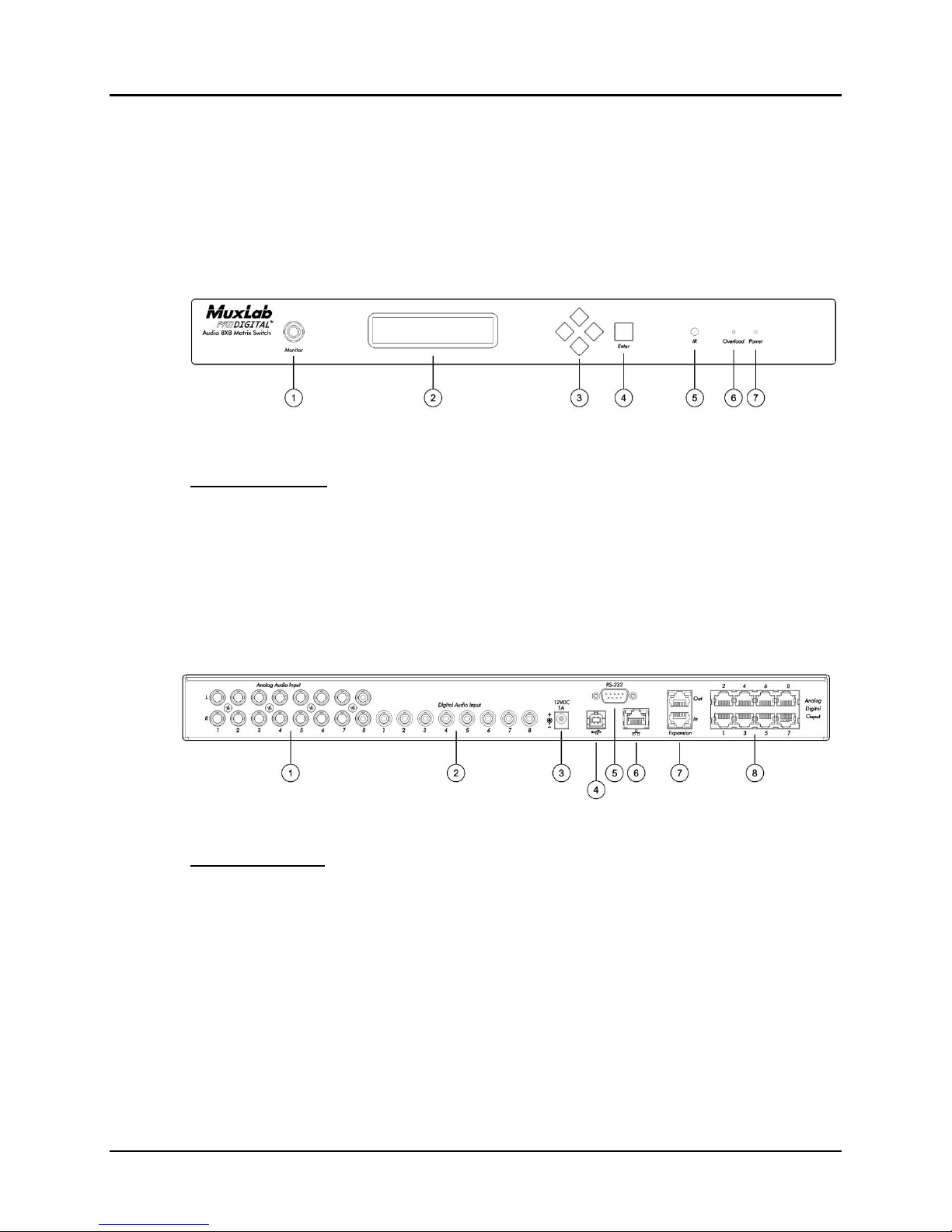
Figure 2: Front Panel
Front Panel Legend
1. Monitor port
2. Display
3. Navigation pushbuttons
4. Enter pushbutton
5. IR sensor
6. Overload indicator (blue LED)
7. Power indicator (blue LED)
Back Panel Legend
1. Analog audio input ports (RCA connector)
2. Digital audio input ports (RCA connector)
3. Power supply port (2.1 MM barrel connector)
4. Remote interface port (USB)
5. Remote interface port (RS-232)
6. Remote interface port (RJ45)
7. Expansion input/output ports (RJ45)
8. Analog digital output ports (RJ45)
Figure 3: Back Panel
Page 8

© MuxLab Inc. Audio 8x8 Matrix Switch Installation Guide
3.3.
Pre-Installation Checklist
The Audio 8x8 Matrix Switch provides a centralized switching center via UTP cables.
1. The Matrix Switch is used in conjunction with MuxLab hi-fi analog balun
(500028) and digital balun (500020).
2. The Matrix Switch is typically installed in a remote telecom room and is connected
to multiple video sources and display devices via Cat 5e/6 UTP. A MuxLab balun
is installed at each receiver/amplifier/audio source to support the connection to the
Matrix Switch via a Cat 5e/6 cable.
Page 9
© MuxLab Inc. Audio 8x8 Matrix Switch Installation Guide
3.4.
Physical Installation
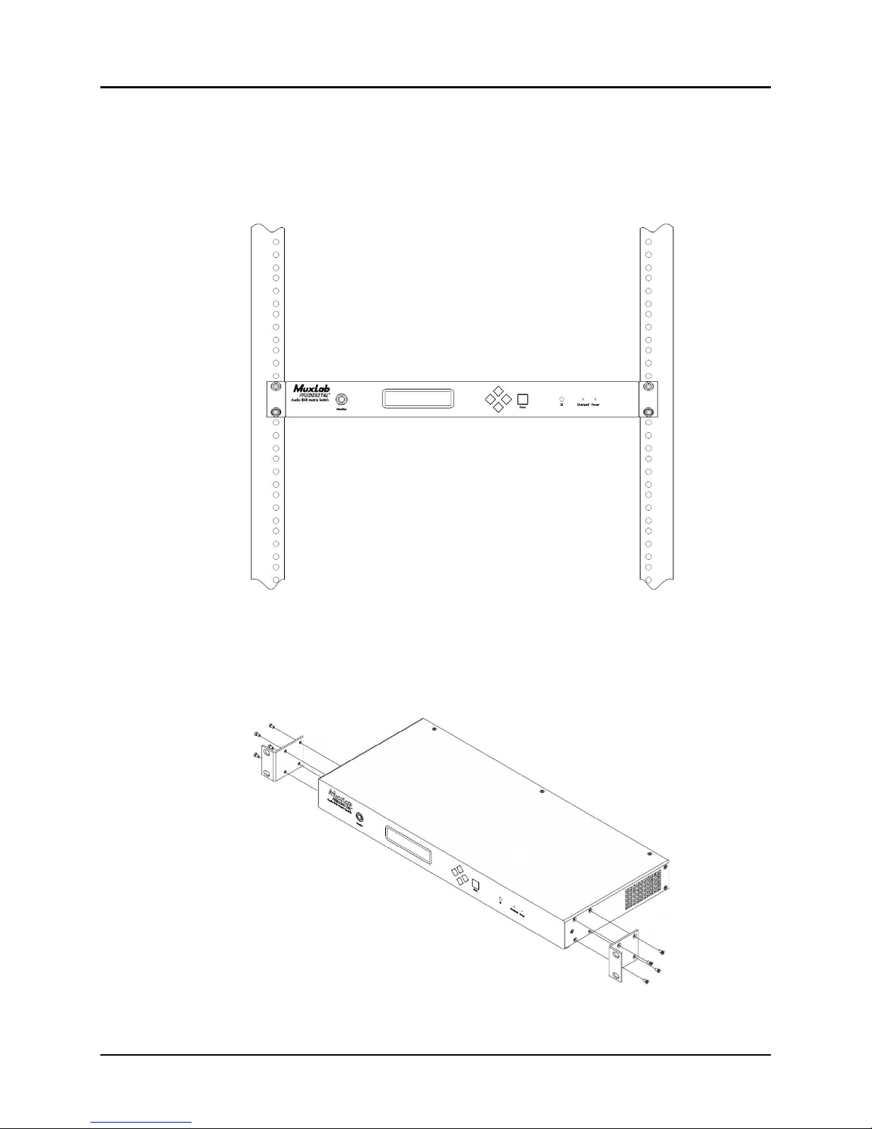
MuxLab’s Audio 8x8 Matrix Switch comes with mounting brackets for standard 19”
rack mounting. Select the final destination for the product and install the unit using
standard rack-mount screws (Figure 4).
Figure 4: Setup for Rackmount Installation
For set-top installation, the side mounting brackets may be removed, and the included
rubber feet placed on the bottom of the unit. When removing the mounting brackets,
be careful to keep and reinstall the four screws on each side of the unit (Figure 5).
Figure 5: Setup for Set-top Installation
Page 10

© MuxLab Inc. Audio 8x8 Matrix Switch Installation Guide
3.5.
Installation Procedure
In order to install the Audio 8x8 Matrix Switch, please follow the steps below:
1. Place the Matrix Switch in its final location (see Section 3.4 Physical Installation).
2. Ensure that power is OFF on all sources and outputs.
3. Connect all sources and outputs to the Matrix Switch.
4. Connect the external 12 VDC power supply to the Matrix Switch and plug the
power supply into an AC power outlet.
5. Power up all equipment.
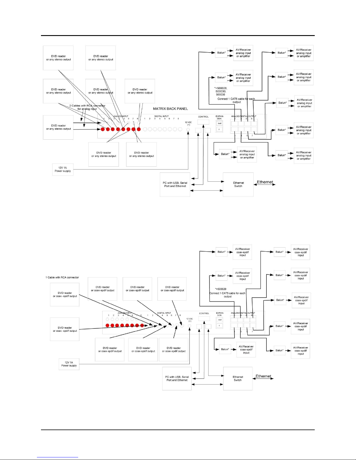
6. Figures 6 and 7 show some typical configurations.
The Matrix Switch is now ready to use. See Section 3.7 Manual Control for
instructions on usage.
Page 11
© MuxLab Inc. Audio 8x8 Matrix Switch Installation Guide
Figure 6: Typical Configuration: Analog Signal (Stereo)
Figure 7: Typical Configuration: Digital Signal (SPDIF – Coaxial)
Page 12
© MuxLab Inc. Audio 8x8 Matrix Switch Installation Guide
3.6.
Manual Control of Matrix Switch
The Audio 8x8 Matrix Switch may be manually controlled by using pushbuttons on its
front panel (Figure 8). It can also be controlled remotely via a keyboard.
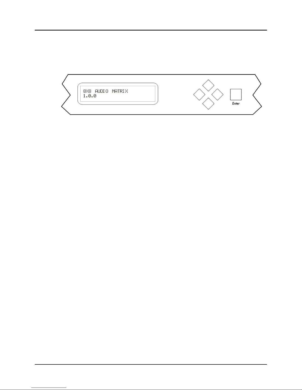
Figure 8: Front Panel Display Screen and Controls
There is one display screen and five controls pushbuttons on the front panel of the
Matrix Switch. The display screen is a blue LCD screen that presents the user with
menus for controlling the Matrix Switch. Of the five control pushbuttons, four are
navigation controls (Up, Down, Left, Right) arranged in a lozenge formation that
enable the user to navigate the menus shown on the LCD screen. The fifth control
pushbutton, a large square labeled Enter, allows the user to select the current entry
shown on the LCD screen.
Upon powering up, the LCD screen displays two lines of text:
8X8 AUDIO MATRIX [Product name]
1.0.0 [Software version]
If no control pushbutton is pressed for 3 seconds, the LCD screen will display all 8
channel connections in sequence:
OUTPUT_CH1 [Name of output channel 1 (or default name)]
INPUT_CH1 [Name of input connected to output channel ,
NO INPUT or TEST TONE]
If any control pushbutton is pressed, the LCD screen will switch to Parameters mode
and display the following:
MAIN FUNCTION:
SELECT INPUT CHANNEL
By pressing the Up or Down control pushbuttons, the LCD screen will switch to
Parameters mode and display the following menu sub-options:
MAIN FUNCTION:
MONITOR CHANNEL
or
MAIN FUNCTION:
OUTPUT VOLUME
or
Page 13

© MuxLab Inc. Audio 8x8 Matrix Switch Installation Guide
MAIN FUNCTION:
OTHER FUNCTIONS
If the Enter pushbutton is pressed, the LCD screen will display the selected menu suboption.
If the Enter pushbutton is not pressed, the LCD screen will revert back to displaying
all 8 channel connections in sequence.
SELECT INPUT CHANNEL Sub-menu
• Use the Up and Down pushbuttons to select output channels.
• Use the Left and Right pushbuttons to select input channels (the monitor connector
on the front panel will provide the sound connected to a given input channel).
• Press the Enter pushbutton once to save your selections.
• Press the Enter pushbutton a second time to return to the top level menu.
• Do not press any pushbuttons in order to return to the top level menu without
making changes.
MONITOR Sub-menu
• Use the Up and Down pushbuttons to select the input channel to monitor via the
monitor connector on the front panel.
• Press the Enter pushbutton once to save your selections.
• Press the Enter pushbutton a second time to return to the top level menu.
• Do not press any pushbuttons in order to return to the top level menu without
making changes.
OUTPUT VOLUME Sub-menu
• Use the Up and Down pushbuttons to select the output channel volume to modify.
• Use the Left and Right pushbuttons to change the attenuation (in dB) of the selected
output channel.
• Press the Enter pushbutton once to save your selections.
• Press the Enter pushbutton a second time to return to the top level menu.
• Do not press any pushbuttons in order to return to the top level menu without
making changes.
OTHER FUNCTIONS Sub-menu
• Use the Up and Down pushbuttons to select version display, IP address,
MASTER/SLAVE CLOCK mode and number of EXTERNAL PORT.
• Press the Enter pushbutton to return to the top level menu.
Page 14
 Loading...