

MuxLab 500040, 500041, 500042, 500043 Quick Installation Manual
8495 Dalton Road, Mount Royal, Quebec, Canada. H4T 1V5
Tel: (514) 905-0588 Fax: (514) 905-0589
Toll Free (North America): (877) 689-5228
E-mail: videoease@muxlab.com URL: www.muxlab.com
© MuxLab Inc. 94-000606-C SE-000579-C
Specifications
Environment
VGA. VESA VP&D 1.0, VIP ver 2.0
Devices
CRT/LCD monitors, plasma, laptops, PCs, projectors.
Transmission
Transparent to the user
Bandwidth
DC to 60 MHz
Input Signals
Video: 1.1 Vp-p
H &V sync: TTL standard. 300 kHz max. bandwidth
Insertion Loss
Less than 3 dB per pair over the frequency range
Common Mode Rejection
Ratio (CMRR)
15 kHz -60 dB typ.
100 kHz to 10 MHz -40 dB typ.
200 MHz -20 dB typ.
Return Loss
-15 dB max from DC to 60 MHz
Connectors
500040/500042: DB15 HD Plug, RJ45 Shielded
500041/500043: DB15 HD Receptacle, RJ45 Shielded
Max. Distance via
Cat 5E/6 UTP/STP Cable
VGA: 640x480 pixels (15 MHz) 450 ft (137 m)
SVGA: 800x600 pixels (30 MHz) 350 ft (107 m)
XGA: 1024x768 pixels (60 MHz) 250 ft (76 m)
SXGA: 1280x1024 pixels (100 MHz) 200 ft (61 m)
WXGA: 1366x768 pixels 180 ft (55 m)
RJ45 Pin Configuration
EIA 568 A or B
Reverse Polarity Sensitive
Pin 1(R) Pin 2(T) Balanced – Red
Pin 4(R) Pin 5(T) Balanced – Green
Pin 7(R) Pin 8(T) Unbalanced – Blue (7 sig, 8 gnd)
Pin 3(R) Pin 6(T) Unbalanced – H & V Sync
Compatibility
Not compatible with the VGA Balun (500010, 500011,
500014) or Active VGA Balun Kit (500035. 500036)
Reset button
May be needed when used with certain display devices
Grounding screw
Grounding screw for optional use
Cable
Cat 5E/6 or better unshielded twisted pair (UTP)
Impedance
Input: RGB 75 ohms Output: RGB 100 ohms
Temperature
Operating: 0° to 55°C
Storage: -20° to 85°C Humidity: Up to 95% non-condensing
Enclosure
ABS fire retardant plastic
Dimensions
2.40” x 2.25 x 1.00” (6.10 x 5.72 x 2.54 cm) plus 6” (15 cm)
lead on 500040 and 500042.
Weight
500041/500043: 2.34 oz (66 g)
500040/500042: 3.87 oz (110 g)
Mounting
Free-standing. Separate velcro mounting pad included
Warranty
Lifetime
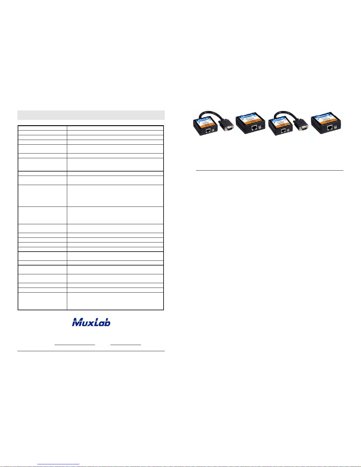
Order Information
500040 VGA Balun II, DB15 HD Plug, PC Side
500041 VGA Balun II, DB15 HD Receptacle, Monitor Side
500042 VGA Balun II, DB15 HD Plug, Monitor Side
500043 VGA Balun II, DB15 HD Receptacle, PC Side
VGA Balun II
500040, 500041, 500042, 500043
Quick Installation Guide
Overview
The VGA Balun II eliminates costly and bulky VGA cable, allowing a VGA source to
be connected to a VGA monitor via one 4-pair Cat 5E/6 unshielded twisted pair (UTP)
cable. Used in pairs, the VGA Balun II allows VGA video to be transmitted up to 350 ft
(107 m) via a Cat 5E/6 UTP cable at 800x600 resolution. Each VGA connection
requires a VGA Balun II at the source (500040, 500043) and a VGA Balun II (500041
or 500042) at the display.
NOTES
• The VGA Balun II does not support VGA handshaking and control signals. Therefore
it is necessary to set the monitor attributes prior to installing the VGA Baluns. In order
to do this, first connect the standard VGA cable directly from the PC to the monitor
and then set the monitor attributes to the required settings (i.e., resolution, color, etc.).
Also, in order to achieve optimum results via twisted pair, set the Contrast and
Brightness levels to maximum.
• The shield on the RJ45 connector is provided as an option for use in harsh electrical
environments where shielded twisted pair cable (STP) may provide additional noise
immunity. When using STP, ensure that the shield on both sides is grounded.
© MuxLab Inc.
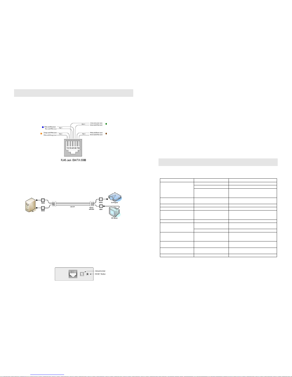
Installation
1. Connect the 500040 or 500043 to the VGA output of the PC or VGA distribution
amplifier. Tighten the mounting screws on each balun.
2. Connect a Cat 5E/6 4-pair cable from the modular RJ45 jack of the 500040 or
500043 to the twisted pair cabling of the building. Wiring must be straight-through
and according to EIA 568A or 568B as shown in the following diagram.
3. Connect a 500041 or 500042 to the VGA input of the display.
4. Connect a Cat 5E/6 4-pair cable from the RJ45 connector of the 500041/500042 to
the twisted pair cabling of the building.
5. Power on the PC and VGA monitor.
6. Set monitor Contrast and Brightness to the desired levels. See typical application
below.
7. Set the monitor refresh rate to 60 Hz.
8. Due to the fact that some displays are more sensitive than others and may not sync
up correctly, a RESET button is provided on each VGA Balun II to allow these
displays to re-synchronize. A RESET button is on both the transmit and receive
side baluns for greater convenience and ease of access. If the initial setup yields an
improperly positioned image on the screen, using a pen or small screw driver, press
the RESET button located next to RJ45 jack on one of the baluns and then
immediately press the AUTOSET button located on the display unit. During this
time the image will change hue and gradually return to normal after approximately
fifteen (15) seconds. Please see diagram below.
Note: Some displays do not require the AUTOSET button to be pressed.
9. Set monitor Contrast and Brightness to the desired levels.
Note: In order to avoid accidentally resetting the connection, the Screensaver options
under Windows Display Settings must be set as follows:
a. Choose any screensaver except “NONE”
b. The “Turn Off Monitor” setting must be set to “NEVER”
10. The VGA Balun features an optional grounding screw (see diagram above) that
may be used to clear up any image anomalies. For example, under some
conditions, there may be a slight difference in hue between the left hand side of
screen and the right. Connecting the ground terminal to earth ground will help clear
this up. However, if there is a ground loop problem in the building, connecting the
ground terminal may negatively affect the image. Therefore the ground screw
should only be used if it improves the overall image quality.
Note: During start-up, there may be a two (2) to three (3) second delay before an image
appears and the initial image may have a yellow hue. This is a normal function of the
product and is required in order to allow the monitor to sync up correctly.
Troubleshooting
The following table describes some of the symptoms, probable causes and possible
solutions in respect to the installation of the VGA Balun II:
Symptom Probable Causes Possible Solutions
No continuity in video link Verify cable continuity between baluns.
Power off Check power supplies of VGA equipment.
No video
PC settings
Perform diagnostics on your VGA
equipment by following the manufacturer’s
instructions.
Image distorted or skewed.
Specific display unable to syncupFollow RESET procedure in manual to force
display to sync up correctly.
Image not stable Defective link or equipment Verify VGA equipment interface integrity.
Unusual colors Reversed polarity Ensure wiring is straight-through polarity.
Background pattern EMI interference
Identify possible radiating frequency sources
Try to isolate them from the video. Use
shielded twisted pair grounded at both ends.
Smearing Exceeded distance Verify cable grade. Use higher grade cable.
Exceeded distance
Verify cable grade. Use higher grade cable if
necessary. Adjust contrast on monitor.
Weak contrast
Unusual link attenuation Verify cable distance using cable tester.
Horizontal bars moving
upward in background
Ground loop problem
Assure that PC and Monitor are connected to
the same ground. Disconnect PC or monitor
from the ground.
1 to 2 pixel object random
dislocation
High noise level in the room.
Distance exceeded.
Set another resolution and refresh rate.
Review connectivity.
Slight variance in hue between
left and right display margins
Slight background noise Connect ground terminal to earth ground.
Shaking image Possible ground loop problem Disconnect gnd terminal from earth ground.
If you still cannot diagnose the problem, please call MuxLab Customer Technical
Support at 877-689-5228 (toll-free in North America) or (+1) 514-905-0588
(International).
 Loading...