

Page 1
MAINTENANCE
MANUAL
Full-ColourInkjetPrinter
VJ-1604
Rev.
VJ1604E-M-00
Use this manual for the maintenance
and inspection of machine.
Page 2

Page 3
Important Notice VJ-1604 Maintenance Manual
Important Notice
1. For Users in Europe
Important:
This is a Class A product approved for industrial environments. In a domestic environment this product may cause
radio interference in which case you may be required to take
adequate measures.
2. For Users in the United States
This equipment has been tested and found to comply with the limits for a Class A digital device, pursuant
to Part 15 of the FCC Rules. These limits are designed to provide reasonable protection against harmful
interference when the equipment is operated in a commercial environment.
This equipment generates, uses, and can radiate radio frequency energy and, if not installed and used in
accordance with the instruction manual, may cause harmful interference to radio communications.
Operation of this equipment in a residential area is likely to cause harmful interference in which case the
user will be required to correct the interference at his own expense.
3. Trademark Mentioned in this Manual
• MUTOH, ValueJet, VJ-1604 are registered trademarks or product names of MUTOH INDUSTRIES
LTD.
• Centronics and BiCentronics are registered trademarks or product names of Centronics Data Computer
Corporation.
• Windows95, Windows98, Windows98SE, Windows NT4.0, Windows2000, Windows XP, and MSDOS are registered trademarks or product names of Microsoft Corporation.
• Intel and Pentium are trademarks or registered trademarks of Intel Corporation.
• Other company and product names may be registered trademarks or product names.
• No part of this product or publication may be reproduced, copied, or
transmitted in any form or by any means, except for personal use,
without the permission of MUTOH INDUSTRIES LTD.
• The product and the contents of this publication may be changed
without prior notification.
• MUTOH INDUSTRIES LTD. has made the best efforts to keep this
publication free from error, but if you find any uncertainties or
misprints, please call us or the shop where you bought this equipment.
• MUTOH INDUSTRIES LTD. shall not be liable for any damages or
troubles resulting from the use of this equipment or this manual.
(1)
Page 4

VJ-1604 Maintenance Manual Warranty Limitations
Warranty Limitations
1. MUTOH INDUSTRIES LTD. warrants part repair or replacement as a sole measure only if a failure is
found in the system or in the materials and workmanship of the product the seller produced.
However, if the cause of failure is uncertain, decide the action after due mutual consultation.
2. The warranty shall not apply to any direct or indirect loss, or compensation for the loss due to the product
that has been subject to misuse, neglect, or improper alternation.
(2)
Page 5
About this Manual VJ-1604 Maintenance Manual
About this Manual
1. Purpose and Target Readers
This manual explains preparations needed before maintaining and checking operations for MUTOH Full
Color Ink Jet Printer (VJ-1604).
This manual is prepared for the maintenance personnel of this printer.
Before using this printer, fully understand the contents and directions in this manual.
2. Manual Configuration
Section Contents
1 Safety Instructions Explains types of warnings, cautions and warnings labeled on the printer
for the both operators of the printer and maintenance personnel.
2 Product Overview Explains the features, part names, and functions of the printer.
3 Specifications Explains the specifications of the printer.
4 Parts Replacement Explains the procedures of replacement and removal of the service parts
of the printer.
5 Self-Diagnostic Mode Explains the self-diagnostic functions of the printer.
6 Maintenance Mode Explains the maintenance mode of the printer.
7 Adjustment Explains the adjusting procedures of the printer parts.
8 Maintenance Explains daily maintenance of the printer.
9 Troubleshooting Explains troubles that may occur when using the printer and how to
solve them.
10 Appendix Explains the maintenance information and the exploded views for this
printer.
Use the built-in self-diagnostic program to locate a defective part and adjust/
check during maintenance.
(3)
Page 6
VJ-1604 Maintenance Manual About this Manual
NOTE
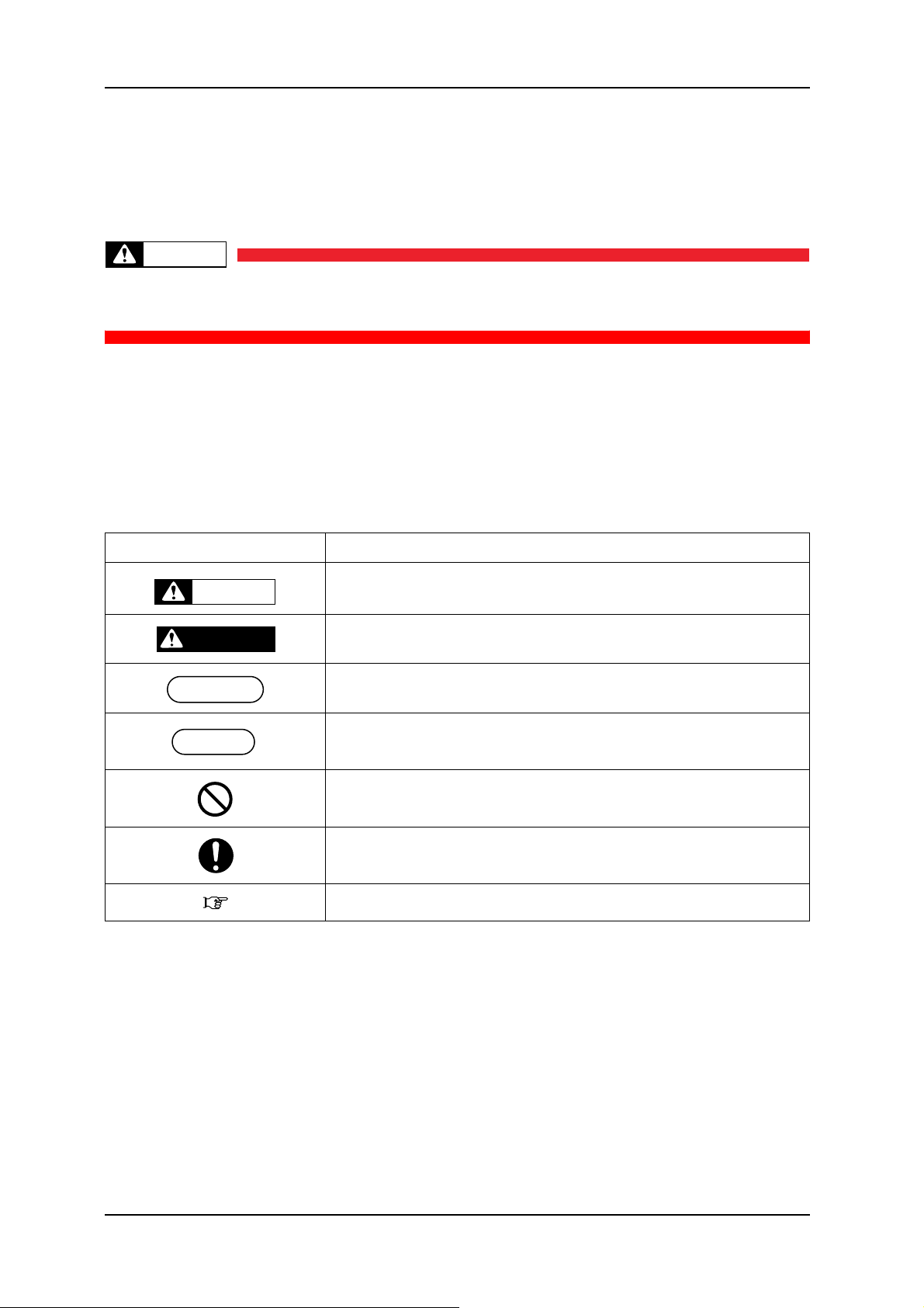
3. Manual Notation
The following symbols are used in this manual for easier understanding of the information.
Symbol Meaning
Must be followed carefully to avoid death or serious bodily injury
WARNING
Must be observed to avoid slight or moderate bodily injury or damage to
CAUTION
your equipment
Contains important information and useful tips on the operation of the
product
Indicates useful tips for operating or understanding the equipment
TIP
Indicates reference pages in this manual
(4)
Page 7

VJ-1604 Maintenance Manual
General Table of Contents
1 Safety Instructions
1.1 Introduction. . . . . . . . . . . . . . . . . . . . . . . . . . . . . . . . . . . . . . . . . . . . . . . . . . 1-2
1.2 Warnings, Cautions and Notes . . . . . . . . . . . . . . . . . . . . . . . . . . . . . . . . . . 1-2
1.3 Important Safety Instructions . . . . . . . . . . . . . . . . . . . . . . . . . . . . . . . . . . . 1-3
1.4 Warning Labels . . . . . . . . . . . . . . . . . . . . . . . . . . . . . . . . . . . . . . . . . . . . . . . 1-6
1.4.1 Handling the Warning Labels . . . . . . . . . . . . . . . . . . . . . . . . . . . . . . . . . 1-6
1.4.2 Locations and Types of Warning Labels . . . . . . . . . . . . . . . . . . . . . . . . 1-7
1.5 Operation Labels. . . . . . . . . . . . . . . . . . . . . . . . . . . . . . . . . . . . . . . . . . . . . . 1-9
1.5.1 Handling the Operation Labels. . . . . . . . . . . . . . . . . . . . . . . . . . . . . . . . 1-9
1.5.2 Locations and Types of Operation Labels . . . . . . . . . . . . . . . . . . . . . . 1-10
2 Product Overview
2.1 Introduction. . . . . . . . . . . . . . . . . . . . . . . . . . . . . . . . . . . . . . . . . . . . . . . . . . 2-2
2.2 Features. . . . . . . . . . . . . . . . . . . . . . . . . . . . . . . . . . . . . . . . . . . . . . . . . . . . . 2-2
2.3 Part Names and Functions. . . . . . . . . . . . . . . . . . . . . . . . . . . . . . . . . . . . . . 2-3
2.3.1 Front Section . . . . . . . . . . . . . . . . . . . . . . . . . . . . . . . . . . . . . . . . . . . . . 2-4
2.3.2 Rear Section. . . . . . . . . . . . . . . . . . . . . . . . . . . . . . . . . . . . . . . . . . . . . . 2-5
2.3.3 Operation Panel . . . . . . . . . . . . . . . . . . . . . . . . . . . . . . . . . . . . . . . . . . . 2-6
2.4 Printer Status . . . . . . . . . . . . . . . . . . . . . . . . . . . . . . . . . . . . . . . . . . . . . . . . 2-9
2.4.1 Normal . . . . . . . . . . . . . . . . . . . . . . . . . . . . . . . . . . . . . . . . . . . . . . . . . . 2-9
2.4.2 Setup Menu . . . . . . . . . . . . . . . . . . . . . . . . . . . . . . . . . . . . . . . . . . . . . . 2-9
2.4.3 Self-Diagnosis Function . . . . . . . . . . . . . . . . . . . . . . . . . . . . . . . . . . . . . 2-9
2.4.4 Maintenance Mode. . . . . . . . . . . . . . . . . . . . . . . . . . . . . . . . . . . . . . . . . 2-9
3 Specifications
3.1 Introduction. . . . . . . . . . . . . . . . . . . . . . . . . . . . . . . . . . . . . . . . . . . . . . . . . . 3-2
3.2 Product Specifications. . . . . . . . . . . . . . . . . . . . . . . . . . . . . . . . . . . . . . . . . 3-2
3.3 Interface Specifications . . . . . . . . . . . . . . . . . . . . . . . . . . . . . . . . . . . . . . . . 3-4
3.3.1 USB Interface Specifications. . . . . . . . . . . . . . . . . . . . . . . . . . . . . . . . . 3-4
3.3.2 Network Interface Specifications . . . . . . . . . . . . . . . . . . . . . . . . . . . . . . 3-5
5
Page 8

VJ-1604 Maintenance Manual
3.4 Options/Supplies List. . . . . . . . . . . . . . . . . . . . . . . . . . . . . . . . . . . . . . . . . . 3-5
3.4.1 Options. . . . . . . . . . . . . . . . . . . . . . . . . . . . . . . . . . . . . . . . . . . . . . . . . . 3-5
3.4.2 Supplies . . . . . . . . . . . . . . . . . . . . . . . . . . . . . . . . . . . . . . . . . . . . . . . . . 3-5
3.5 Choosing a Place for the Printer . . . . . . . . . . . . . . . . . . . . . . . . . . . . . . . . 3-6
4 Parts Replacement
4.1 Introduction. . . . . . . . . . . . . . . . . . . . . . . . . . . . . . . . . . . . . . . . . . . . . . . . . . 4-4
4.2 Removal of Covers . . . . . . . . . . . . . . . . . . . . . . . . . . . . . . . . . . . . . . . . . . . . 4-6
4.2.1 Removing R Side Cover. . . . . . . . . . . . . . . . . . . . . . . . . . . . . . . . . . . . . 4-7
4.2.2 Removing Operation Panel Unit. . . . . . . . . . . . . . . . . . . . . . . . . . . . . . . 4-9
4.2.3 Removing L Side Cover . . . . . . . . . . . . . . . . . . . . . . . . . . . . . . . . . . . . 4-10
4.2.4 Removing Ink Holder (I/H) Cover . . . . . . . . . . . . . . . . . . . . . . . . . . . . . 4-11
4.2.5 Removing Front Cover. . . . . . . . . . . . . . . . . . . . . . . . . . . . . . . . . . . . . 4-12
4.2.6 Removing Top Cover . . . . . . . . . . . . . . . . . . . . . . . . . . . . . . . . . . . . . . 4-13
4.2.7 Removing Media Guide F . . . . . . . . . . . . . . . . . . . . . . . . . . . . . . . . . . 4-14
4.2.8 Removing Media Guide R2 . . . . . . . . . . . . . . . . . . . . . . . . . . . . . . . . . 4-15
4.2.9 Removing Scroller Receiver (L, R). . . . . . . . . . . . . . . . . . . . . . . . . . . . 4-15
4.3 Replacement of Board Base Section Components . . . . . . . . . . . . . . . . . 4-17
4.3.1 Removing Connector Panel and Cooling Fan . . . . . . . . . . . . . . . . . . . 4-17
4.3.2 Removing Main Board Bracket . . . . . . . . . . . . . . . . . . . . . . . . . . . . . . 4-18
4.3.3 Replacing Main Board Assembly . . . . . . . . . . . . . . . . . . . . . . . . . . . . . 4-21
4.3.4 Replacing HEATER CONT board assembly . . . . . . . . . . . . . . . . . . . . 4-22
4.3.5 Replacing HEATER RELAY board assembly . . . . . . . . . . . . . . . . . . . 4-25
4.3.6 Replacing Power Board Assembly. . . . . . . . . . . . . . . . . . . . . . . . . . . . 4-27
4.3.7 Replacing Fuse . . . . . . . . . . . . . . . . . . . . . . . . . . . . . . . . . . . . . . . . . . 4-28
4.3.8 Replacing Inlet Assembly. . . . . . . . . . . . . . . . . . . . . . . . . . . . . . . . . . . 4-29
4.4 Replacement of PF Driving Section Components. . . . . . . . . . . . . . . . . . 4-31
4.4.1 Replacing PF Motor Assembly. . . . . . . . . . . . . . . . . . . . . . . . . . . . . . . 4-31
4.4.2 Replacing PF_ENC Assembly . . . . . . . . . . . . . . . . . . . . . . . . . . . . . . . 4-33
4.4.3 Replacing PF_ENC Scale . . . . . . . . . . . . . . . . . . . . . . . . . . . . . . . . . . 4-34
4.4.4 Replacing Heater and Thermistor Assembly . . . . . . . . . . . . . . . . . . . . 4-34
4.5 Replacement of CR Driving Section Components . . . . . . . . . . . . . . . . . 4-38
4.5.1 CR Motor Assembly . . . . . . . . . . . . . . . . . . . . . . . . . . . . . . . . . . . . . . . 4-38
4.5.2 Replacing CR_HP Sensor . . . . . . . . . . . . . . . . . . . . . . . . . . . . . . . . . . 4-39
4.5.3 Replacing Lever Sensor. . . . . . . . . . . . . . . . . . . . . . . . . . . . . . . . . . . . 4-40
4.5.4 Replacing T Fence. . . . . . . . . . . . . . . . . . . . . . . . . . . . . . . . . . . . . . . . 4-41
4.5.5 Replacing CR Driven Pulley. . . . . . . . . . . . . . . . . . . . . . . . . . . . . . . . . 4-44
4.5.6 Replacing Pressure Arm Assembly . . . . . . . . . . . . . . . . . . . . . . . . . . . 4-46
6
Page 9

VJ-1604 Maintenance Manual
4.6 Replacement of Head Section Components . . . . . . . . . . . . . . . . . . . . . . 4-48
4.6.1 Replacing Print Head . . . . . . . . . . . . . . . . . . . . . . . . . . . . . . . . . . . . . . 4-48
4.6.2 Replacing Cutter Holder Assembly . . . . . . . . . . . . . . . . . . . . . . . . . . . 4-52
4.7 Replacement of Maintenance Section Components . . . . . . . . . . . . . . . . 4-57
4.7.1 Removing Maintenance Base Assembly . . . . . . . . . . . . . . . . . . . . . . . 4-57
4.7.2 Replacing Pump Cap Assembly. . . . . . . . . . . . . . . . . . . . . . . . . . . . . . 4-61
4.7.3 Replacing Cleaner Head (Cleaning Wiper) . . . . . . . . . . . . . . . . . . . . . 4-63
4.7.4 Replacing Flushing Box Assembly . . . . . . . . . . . . . . . . . . . . . . . . . . . . 4-64
4.8 Replacement of Ink Supply Section Components . . . . . . . . . . . . . . . . . . 4-66
4.8.1 Replacing Ink Holder (I/H) Assembly . . . . . . . . . . . . . . . . . . . . . . . . . . 4-66
4.8.2 Replacing Ink Sensor Assembly. . . . . . . . . . . . . . . . . . . . . . . . . . . . . . 4-68
4.8.3 Replacing Cover Sensor Assembly . . . . . . . . . . . . . . . . . . . . . . . . . . . 4-70
4.8.4 Replacing Heater Junction Board. . . . . . . . . . . . . . . . . . . . . . . . . . . . . 4-71
4.9 Replacement of Frame Section Components . . . . . . . . . . . . . . . . . . . . . 4-73
4.9.1 Replacing Suction Fan Assembly. . . . . . . . . . . . . . . . . . . . . . . . . . . . . 4-73
4.9.2 Replacing P_REAR Sensor Assembly . . . . . . . . . . . . . . . . . . . . . . . . . 4-74
4.10 Replacement of Cable Guide Section Components . . . . . . . . . . . . . . . . 4-75
4.10.1 Replacing CR Board Assembly . . . . . . . . . . . . . . . . . . . . . . . . . . . . . . 4-75
4.10.2 Replacing Ink Tube . . . . . . . . . . . . . . . . . . . . . . . . . . . . . . . . . . . . . . . 4-76
4.10.3 Replacing CR Tape Wire . . . . . . . . . . . . . . . . . . . . . . . . . . . . . . . . . . . 4-79
5 Self-Diagnosis Mode
5.1 Introduction. . . . . . . . . . . . . . . . . . . . . . . . . . . . . . . . . . . . . . . . . . . . . . . . . . 5-4
5.2 Preparation . . . . . . . . . . . . . . . . . . . . . . . . . . . . . . . . . . . . . . . . . . . . . . . . . . 5-4
5.2.1 Preparations on Machine . . . . . . . . . . . . . . . . . . . . . . . . . . . . . . . . . . . . 5-4
5.2.2 Starting Up . . . . . . . . . . . . . . . . . . . . . . . . . . . . . . . . . . . . . . . . . . . . . . . 5-4
5.3 Operations in Self-Diagnosis Mode . . . . . . . . . . . . . . . . . . . . . . . . . . . . . . 5-6
5.3.1 Operating Self-Diagnosis Mode . . . . . . . . . . . . . . . . . . . . . . . . . . . . . . . 5-6
5.3.2 Diagnosis Items in Self-Diagnosis Menu . . . . . . . . . . . . . . . . . . . . . . . . 5-8
5.4 Platen Adjustment Menu . . . . . . . . . . . . . . . . . . . . . . . . . . . . . . . . . . . . . . 5-10
5.5 Inspection Menu . . . . . . . . . . . . . . . . . . . . . . . . . . . . . . . . . . . . . . . . . . . . . 5-11
5.5.1 Memory Size Menu . . . . . . . . . . . . . . . . . . . . . . . . . . . . . . . . . . . . . . . 5-12
5.5.2 Version Menu . . . . . . . . . . . . . . . . . . . . . . . . . . . . . . . . . . . . . . . . . . . . 5-13
5.5.3 Operation Panel Menu . . . . . . . . . . . . . . . . . . . . . . . . . . . . . . . . . . . . . 5-14
5.5.4 Sensor Menu . . . . . . . . . . . . . . . . . . . . . . . . . . . . . . . . . . . . . . . . . . . . 5-15
5.5.5 Encoder Menu . . . . . . . . . . . . . . . . . . . . . . . . . . . . . . . . . . . . . . . . . . . 5-17
5.5.6 Fan Menu . . . . . . . . . . . . . . . . . . . . . . . . . . . . . . . . . . . . . . . . . . . . . . . 5-17
7
Page 10

VJ-1604 Maintenance Manual
5.5.7 History Menu . . . . . . . . . . . . . . . . . . . . . . . . . . . . . . . . . . . . . . . . . . . . 5-18
5.5.8 Head Waveform Menu . . . . . . . . . . . . . . . . . . . . . . . . . . . . . . . . . . . . . 5-21
5.6 Ink Charging Menu . . . . . . . . . . . . . . . . . . . . . . . . . . . . . . . . . . . . . . . . . . . 5-22
5.7 Adjustment Menu . . . . . . . . . . . . . . . . . . . . . . . . . . . . . . . . . . . . . . . . . . . . 5-23
5.7.1 Head Nozzle Check Menu . . . . . . . . . . . . . . . . . . . . . . . . . . . . . . . . . . 5-24
5.7.2 Skew Check Menu . . . . . . . . . . . . . . . . . . . . . . . . . . . . . . . . . . . . . . . . 5-27
5.7.3 Head Slant Check Menu . . . . . . . . . . . . . . . . . . . . . . . . . . . . . . . . . . . 5-28
5.7.4 Voltage Adjustment . . . . . . . . . . . . . . . . . . . . . . . . . . . . . . . . . . . . . . . 5-30
5.7.5 Uni-D / Bi-D Low Adjustment . . . . . . . . . . . . . . . . . . . . . . . . . . . . . . . . 5-32
5.7.6 Uni-D / Bi-D High Adjustment. . . . . . . . . . . . . . . . . . . . . . . . . . . . . . . . 5-36
5.7.7 Side Margin Adjustment Menu. . . . . . . . . . . . . . . . . . . . . . . . . . . . . . . 5-40
5.7.8 Test Printing Menu. . . . . . . . . . . . . . . . . . . . . . . . . . . . . . . . . . . . . . . . 5-41
5.7.9 HeadWash Menu . . . . . . . . . . . . . . . . . . . . . . . . . . . . . . . . . . . . . . . . . 5-42
5.7.10 Software Counter Initialization Menu . . . . . . . . . . . . . . . . . . . . . . . . . . 5-43
5.7.11 Feed Pitch Check Menu. . . . . . . . . . . . . . . . . . . . . . . . . . . . . . . . . . . . 5-44
5.7.12 Solid Print Menu. . . . . . . . . . . . . . . . . . . . . . . . . . . . . . . . . . . . . . . . . . 5-45
5.8 Cleaning Menu . . . . . . . . . . . . . . . . . . . . . . . . . . . . . . . . . . . . . . . . . . . . . . 5-46
5.9 Sample Printing Menu . . . . . . . . . . . . . . . . . . . . . . . . . . . . . . . . . . . . . . . . 5-47
5.10 Time Setting . . . . . . . . . . . . . . . . . . . . . . . . . . . . . . . . . . . . . . . . . . . . . . . . 5-48
5.11 Parameter Menu . . . . . . . . . . . . . . . . . . . . . . . . . . . . . . . . . . . . . . . . . . . . . 5-48
5.11.1 Parameter Initialization Menu. . . . . . . . . . . . . . . . . . . . . . . . . . . . . . . . 5-49
5.11.2 Parameter Update Menu . . . . . . . . . . . . . . . . . . . . . . . . . . . . . . . . . . . 5-51
5.12 Servo Setting . . . . . . . . . . . . . . . . . . . . . . . . . . . . . . . . . . . . . . . . . . . . . . . 5-56
5.13 Endurance Running Menu . . . . . . . . . . . . . . . . . . . . . . . . . . . . . . . . . . . . . 5-58
5.13.1 CR Motor Endurance Menu . . . . . . . . . . . . . . . . . . . . . . . . . . . . . . . . . 5-59
5.13.2 PF Motor Endurance Menu . . . . . . . . . . . . . . . . . . . . . . . . . . . . . . . . . 5-60
5.13.3 Wiper Motor Endurance Menu . . . . . . . . . . . . . . . . . . . . . . . . . . . . . . . 5-61
5.13.4 Pump Endurance Menu . . . . . . . . . . . . . . . . . . . . . . . . . . . . . . . . . . . . 5-62
5.13.5 Print Head Endurance (Nozzle Print) Menu. . . . . . . . . . . . . . . . . . . . . 5-63
5.13.6 General Endurance Menu . . . . . . . . . . . . . . . . . . . . . . . . . . . . . . . . . . 5-64
5.13.7 Endurance Running Check Menu . . . . . . . . . . . . . . . . . . . . . . . . . . . . 5-65
5.14 Media Feed Menu . . . . . . . . . . . . . . . . . . . . . . . . . . . . . . . . . . . . . . . . . . . . 5-65
5.15 ExControl Menu . . . . . . . . . . . . . . . . . . . . . . . . . . . . . . . . . . . . . . . . . . . . . 5-66
5.15.1 Version. . . . . . . . . . . . . . . . . . . . . . . . . . . . . . . . . . . . . . . . . . . . . . . . . 5-66
5.15.2 Sensor . . . . . . . . . . . . . . . . . . . . . . . . . . . . . . . . . . . . . . . . . . . . . . . . . 5-67
5.15.3 Heater . . . . . . . . . . . . . . . . . . . . . . . . . . . . . . . . . . . . . . . . . . . . . . . . . 5-68
5.15.4 History . . . . . . . . . . . . . . . . . . . . . . . . . . . . . . . . . . . . . . . . . . . . . . . . . 5-69
8
Page 11

VJ-1604 Maintenance Manual
5.16 PaperInitial Menu . . . . . . . . . . . . . . . . . . . . . . . . . . . . . . . . . . . . . . . . . . . . 5-69
6 Maintenance Mode
6.1 Introduction. . . . . . . . . . . . . . . . . . . . . . . . . . . . . . . . . . . . . . . . . . . . . . . . . . 6-2
6.2 Operations in Maintenance Mode . . . . . . . . . . . . . . . . . . . . . . . . . . . . . . . . 6-2
6.2.1 Starting Up the Maintenance Mode . . . . . . . . . . . . . . . . . . . . . . . . . . . . 6-2
6.2.2 Operating Maintenance Mode . . . . . . . . . . . . . . . . . . . . . . . . . . . . . . . . 6-2
6.3 Maintenance Menu . . . . . . . . . . . . . . . . . . . . . . . . . . . . . . . . . . . . . . . . . . . . 6-3
6.3.1 Counter Display Menu . . . . . . . . . . . . . . . . . . . . . . . . . . . . . . . . . . . . . . 6-3
6.3.2 Counter Initialization Menu. . . . . . . . . . . . . . . . . . . . . . . . . . . . . . . . . . . 6-6
6.3.3 Counter Print Menu . . . . . . . . . . . . . . . . . . . . . . . . . . . . . . . . . . . . . . . . 6-7
6.3.4 Media Feed Menu . . . . . . . . . . . . . . . . . . . . . . . . . . . . . . . . . . . . . . . . . 6-8
7 Adjustment
7.1 Introduction. . . . . . . . . . . . . . . . . . . . . . . . . . . . . . . . . . . . . . . . . . . . . . . . . . 7-3
7.2 Adjustment Item . . . . . . . . . . . . . . . . . . . . . . . . . . . . . . . . . . . . . . . . . . . . . . 7-3
7.3 Working with Dedicated Network Software . . . . . . . . . . . . . . . . . . . . . . . . 7-8
7.3.1 Parameter Backup . . . . . . . . . . . . . . . . . . . . . . . . . . . . . . . . . . . . . . . . . 7-8
7.3.2 Jigs and Tools . . . . . . . . . . . . . . . . . . . . . . . . . . . . . . . . . . . . . . . . . . . . 7-8
7.3.3 Required Environment . . . . . . . . . . . . . . . . . . . . . . . . . . . . . . . . . . . . . . 7-9
7.3.4 Receiving Parameters . . . . . . . . . . . . . . . . . . . . . . . . . . . . . . . . . . . . . 7-12
7.3.5 Firmware Installation . . . . . . . . . . . . . . . . . . . . . . . . . . . . . . . . . . . . . . 7-13
7.3.6 Sending Parameters. . . . . . . . . . . . . . . . . . . . . . . . . . . . . . . . . . . . . . . 7-17
7.3.7 Sub Controller Installation . . . . . . . . . . . . . . . . . . . . . . . . . . . . . . . . . . 7-18
7.3.8 RTC Date & Time Setting. . . . . . . . . . . . . . . . . . . . . . . . . . . . . . . . . . . 7-19
7.4 PF Speed Reduction Belt Tension Adjustment . . . . . . . . . . . . . . . . . . . . 7-20
7.4.1 Jigs and Tools . . . . . . . . . . . . . . . . . . . . . . . . . . . . . . . . . . . . . . . . . . . 7-20
7.4.2 Adjustment Procedure . . . . . . . . . . . . . . . . . . . . . . . . . . . . . . . . . . . . . 7-20
7.5 PF Encoder Assembly Position Adjustment . . . . . . . . . . . . . . . . . . . . . . 7-22
7.5.1 Adjustment Procedure . . . . . . . . . . . . . . . . . . . . . . . . . . . . . . . . . . . . . 7-22
7.6 CR Belt Tension Adjustment . . . . . . . . . . . . . . . . . . . . . . . . . . . . . . . . . . . 7-24
7.7 Head Alignment (Horizontal Height) . . . . . . . . . . . . . . . . . . . . . . . . . . . . . 7-25
7.8 Head Alignment (Vertical Slant) . . . . . . . . . . . . . . . . . . . . . . . . . . . . . . . . 7-27
7.9 Cutter Holder Height Adjustment . . . . . . . . . . . . . . . . . . . . . . . . . . . . . . . 7-29
7.9.1 Jigs and Tools . . . . . . . . . . . . . . . . . . . . . . . . . . . . . . . . . . . . . . . . . . . 7-29
7.9.2 Adjustment Procedure . . . . . . . . . . . . . . . . . . . . . . . . . . . . . . . . . . . . . 7-29
9
Page 12

VJ-1604 Maintenance Manual
7.10 PG Height Adjustment . . . . . . . . . . . . . . . . . . . . . . . . . . . . . . . . . . . . . . . . 7-31
7.10.1 Jigs and Tools . . . . . . . . . . . . . . . . . . . . . . . . . . . . . . . . . . . . . . . . . . . 7-31
7.10.2 Adjustment Procedure . . . . . . . . . . . . . . . . . . . . . . . . . . . . . . . . . . . . . 7-31
7.11 Media Sensor Sensitivity Adjustment . . . . . . . . . . . . . . . . . . . . . . . . . . . 7-32
7.11.1 P_EDGE Sensor Sensitivity Adjustment . . . . . . . . . . . . . . . . . . . . . . . 7-32
7.11.2 P_REAR Sensor Adjustment . . . . . . . . . . . . . . . . . . . . . . . . . . . . . . . . 7-35
8 Maintenance
8.1 Introduction. . . . . . . . . . . . . . . . . . . . . . . . . . . . . . . . . . . . . . . . . . . . . . . . . . 8-2
8.2 Periodical Services. . . . . . . . . . . . . . . . . . . . . . . . . . . . . . . . . . . . . . . . . . . . 8-3
8.3 Part Life Information . . . . . . . . . . . . . . . . . . . . . . . . . . . . . . . . . . . . . . . . . . 8-4
8.4 Lubrication/Bonding . . . . . . . . . . . . . . . . . . . . . . . . . . . . . . . . . . . . . . . . . . 8-6
8.5 Transportation of Printer . . . . . . . . . . . . . . . . . . . . . . . . . . . . . . . . . . . . . . . 8-7
9 Troubleshooting
9.1 Introduction. . . . . . . . . . . . . . . . . . . . . . . . . . . . . . . . . . . . . . . . . . . . . . . . . . 9-2
9.2 Troubleshooting with Error Messages . . . . . . . . . . . . . . . . . . . . . . . . . . . . 9-2
9.2.1 Operation Status . . . . . . . . . . . . . . . . . . . . . . . . . . . . . . . . . . . . . . . . . . 9-3
9.2.2 Errors with Message . . . . . . . . . . . . . . . . . . . . . . . . . . . . . . . . . . . . . . . 9-5
9.2.3 Data Errors. . . . . . . . . . . . . . . . . . . . . . . . . . . . . . . . . . . . . . . . . . . . . . 9-12
9.2.4 Command Errors . . . . . . . . . . . . . . . . . . . . . . . . . . . . . . . . . . . . . . . . . 9-14
9.2.5 Errors Requiring Reboot . . . . . . . . . . . . . . . . . . . . . . . . . . . . . . . . . . . 9-15
9.2.6 Error Messages During File Transmission. . . . . . . . . . . . . . . . . . . . . . 9-29
9.3 Troubleshooting Without Error Messages. . . . . . . . . . . . . . . . . . . . . . . . 9-33
9.3.1 Initial Operation Problems . . . . . . . . . . . . . . . . . . . . . . . . . . . . . . . . . . 9-33
9.3.2 Media Feed Problems . . . . . . . . . . . . . . . . . . . . . . . . . . . . . . . . . . . . . 9-42
9.3.3 Printing Problems. . . . . . . . . . . . . . . . . . . . . . . . . . . . . . . . . . . . . . . . . 9-44
9.3.4 Noise Problems . . . . . . . . . . . . . . . . . . . . . . . . . . . . . . . . . . . . . . . . . . 9-62
9.3.5 Online Function Problems . . . . . . . . . . . . . . . . . . . . . . . . . . . . . . . . . . 9-65
9.3.6 Other Problems . . . . . . . . . . . . . . . . . . . . . . . . . . . . . . . . . . . . . . . . . . 9-68
9.3.7 Problems in Using Dedicated Network Software . . . . . . . . . . . . . . . . . 9-71
10 Appendix
10.1 Introduction. . . . . . . . . . . . . . . . . . . . . . . . . . . . . . . . . . . . . . . . . . . . . . . . . 10-2
10.2 Wiring Diagram . . . . . . . . . . . . . . . . . . . . . . . . . . . . . . . . . . . . . . . . . . . . . . 10-2
10
Page 13

VJ-1604 Maintenance Manual
10.3 Maintenance Part List. . . . . . . . . . . . . . . . . . . . . . . . . . . . . . . . . . . . . . . . . 10-2
10.4 Jigs and Tools. . . . . . . . . . . . . . . . . . . . . . . . . . . . . . . . . . . . . . . . . . . . . . . 10-8
10.4.1 Required Tools . . . . . . . . . . . . . . . . . . . . . . . . . . . . . . . . . . . . . . . . . . . 10-8
10.5 Exploded View. . . . . . . . . . . . . . . . . . . . . . . . . . . . . . . . . . . . . . . . . . . . . . 10-10
11
Page 14

VJ-1604 Maintenance Manual
12
Page 15

VJ-1604 Maintenance Manual 1 Safety Instructions
1 Safety Instructions
1.1 Introduction ............................................................................................. 1- 2
1.2 Warnings, Cautions and Notes.............................................................. 1- 2
1.3 Important Safety Instructions ................................................................ 1- 3
1.4 Warning Labels ....................................................................................... 1- 6
1.4.1 Handling the Warning Labels......................................................... 1-6
1.4.2 Locations and Types of Warning Labels........................................ 1-7
1-1 Rev.-00
Page 16
1 Safety Instructions VJ-1604 Maintenance Manual
NOTE
1.1 Introduction
This chapter explains the meaning of safety terms for personnel who installs, operates, or maintains this
equipment, important safety instructions, and the warning labels attached to the equipment.
WARNING
Make sure to follow all instructions and warnings on this manual when installing, operating,
or maintaining the equipment.
1.2 Warnings, Cautions and Notes
Safety terms in this manual and the contents of warning labels attached to the printer are categorized into the
following three types depending on the degree of risk (or the scale of accident).
Read the following explanations carefully, and follow the instructions in this manual.
Table 1-1 Safety Terms Descriptions
Safety terms Details
Must be followed carefully to avoid death or serious bodily injury
WARNING
DANGER
Must be observed to avoid slight or moderate bodily injury or damage to
whole or part of the product
Contains important information and useful tips on the operation of the
product
Indicates useful tips for operating or understanding the printer
TIP
Indicates “prohibited” operations
Indicates required operations
Indicates reference page in this manual
Rev.-00 1-2
Page 17
VJ-1604 Maintenance Manual 1 Safety Instructions
1.3 Important Safety Instructions
General safety instructions that must be observed to use the equipment safely are explained below.
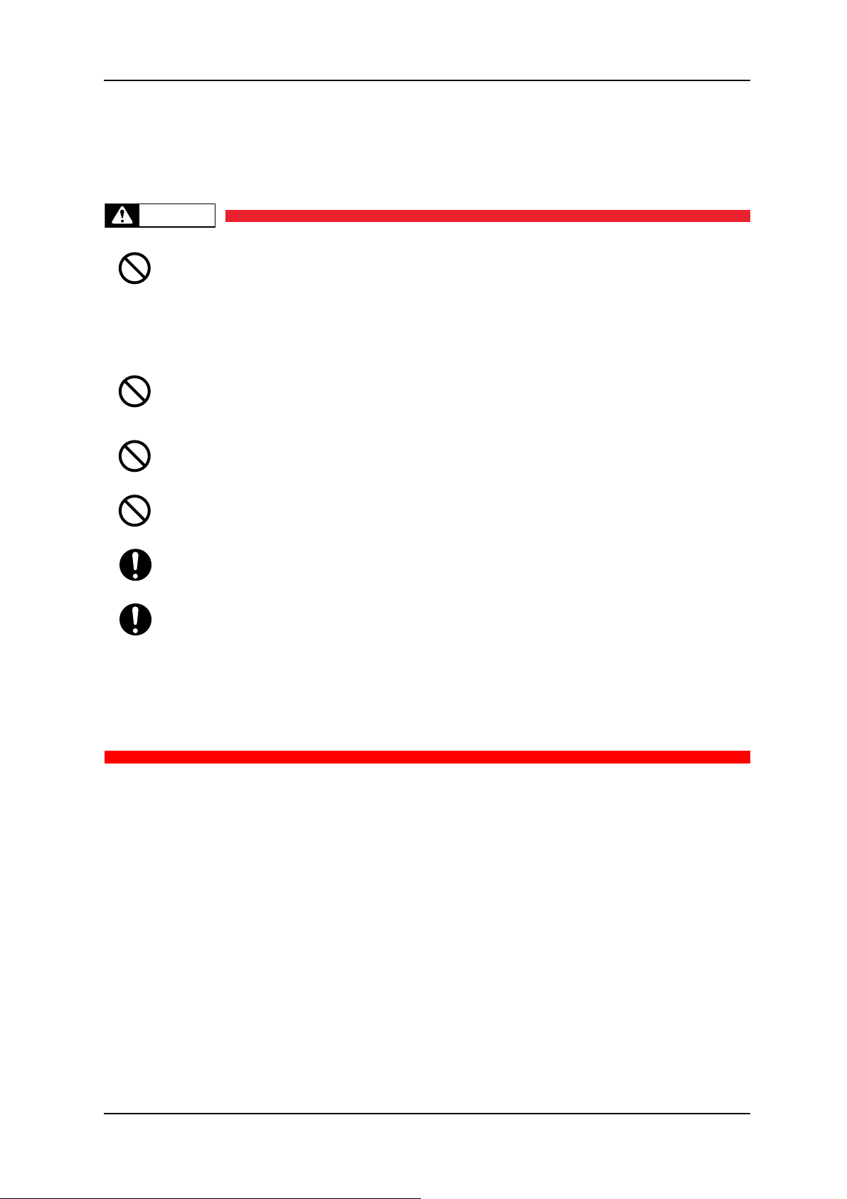
WARNING
Do not place the printer in the following areas. Doing so may result in the printer
tipping or falling over and causing injury.
• Unstable surfaces
• Angled place
• Areas subject to vibration by other equipment
Do not stand on or place heavy objects on your printer. Doing so may result in the
printer tipping or falling over and causing injury.
Doing so could obstruct ventilation and cause fire.
Do not cover the ventilation hole of your printer with cloth, such as a blanket or table
cloth.Doing so may result in fire.
Do not place the printer in humid and dusty areas. Doing so may result in electrical
shock or fire.
Make sure to use the power cable packed with the printer you purchased. Not doing
so may result in electrical shock or fire.
Make sure that the following is performed before parts replacement.
• Turn off the power of the printer.
• Remove the power cable from the power outlet.
Not doing so may cause electric shock or damage to the electric circuit.
• Unplug the cables connected to the printer.
Failure to do so could result in damage to the printer.
1-3 Rev.-00
Page 18
1 Safety Instructions VJ-1604 Maintenance Manual
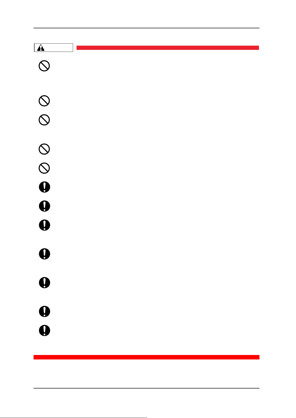
CAUTION
Assembling and disassembling of the printer are possible only for the parts that
disassembling procedures are shown in this manual. Do not disassemble any frame
parts or parts that disassembling procedures are not shown in this manual.
Doing so may cause trouble that cannot be restored, as the printer is originally
assembled in the factory with a high accuracy of 1/100 mm.
Do not touch the elements on the circuit board with bare hands.
Doing so may cause static electricity and break the elements.
Do not press the transparent film on the damper assembly with your hands. Doing so
may discharge the ink filled inside the damper assembly.
Be careful not to damage the transparent film on the damper assembly.
Do not touch the nozzles of the print head. Make sure that the nozzles do not get any
dust.
Never lube the printer mechanism with lube other than that designated by MUTOH.
Doing so may damage the parts or shorten the lifetime.
There are some remaining ink in the tubes. Be careful that the ink is not spilled from the
tube outlet onto the printer or items close to the printer.
If you need to operate the printer with the cover removed for maintenance, be careful
not to get hurt by the driving parts.
If the power board assembly needs to be removed, remove the power cable and wait
for 5 minutes or more before taking it out; this will discharge the residual electrical
charge of the electrolytic capacitor.
Touching the board before the capacitor discharges may cause electric shock.
When connecting or removing an FFC type cable on a MAIN board assembly
connector, make sure to connect or remove the cable perpendicular to the connector.
Connecting or removing at a slant angle may damage, break or short circuit the inner
terminal of the connector. That may damage the elements on the board.
When connecting or removing an FFC type cable on the CR board assembly connector,
make sure to connect or remove the cable perpendicular to the connector.
Connecting or removing at a slant angle may damage, break or short circuit the inner
terminal of the connector. That may damage the elements on the board.
Make sure there is sufficient space around the printer when performing maintenance
work.
Maintenance must be done by more than two person for the following work.
• When disassembling or reassembling the product and the optional stand
• When packing the printer for transportation
Rev.-00 1-4
Page 19

VJ-1604 Maintenance Manual 1 Safety Instructions
NOTE
1.4 Warning Labels
The handling, attachment locations, and types of warning labels are explained below.
Warning labels are attached to areas where care should be taken. Read and understand the positions and
contents thoroughly before maintenance operation.
1.4.1 Handling the Warning Labels
Make sure to note the following when handling the warning labels.
• Make sure that all warning labels can be recognized. If text or illustrations cannot be seen clearly,
clean or replace the label.
• When cleaning warning labels, use a cloth with water or neutral detergent. Do not use a solvent or
gasoline.
• If a warning label is damaged, lost, or cannot be recognized, replace the label.
1-5 Rev.-00
Page 20
1 Safety Instructions VJ-1604 Maintenance Manual
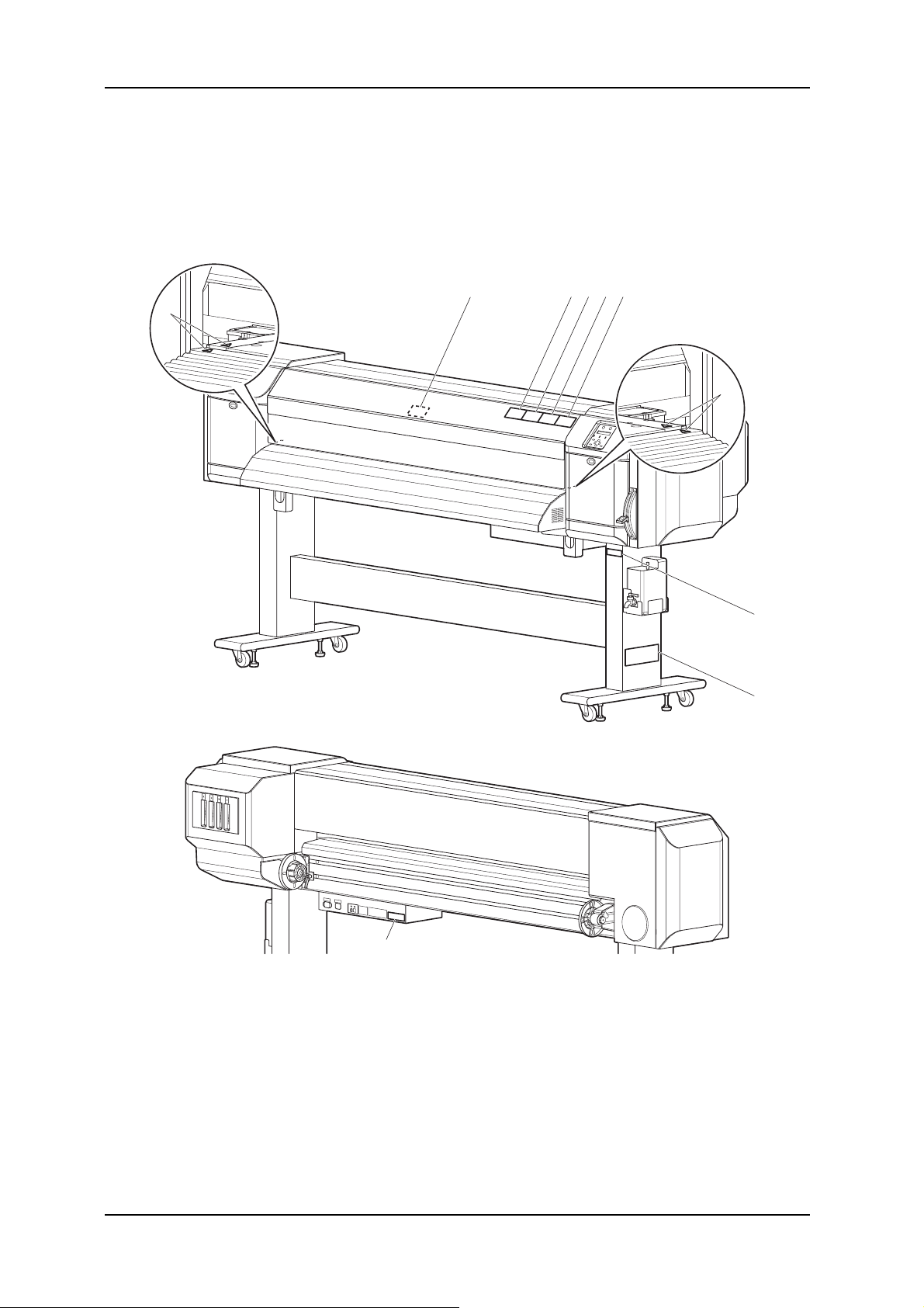
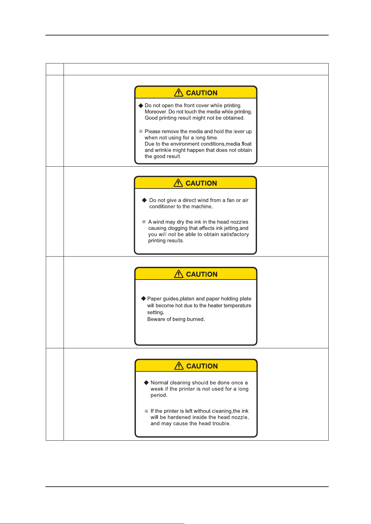
1.4.2 Locations and Types of Warning Labels
(1) Main Body
The locations of warning labels on the main body are shown below.
43215
6
6
9
8
7
Rev.-00 1-6
Page 21
VJ-1604 Maintenance Manual 1 Safety Instructions
Table 1-2 List of Warning Labels
No. Warning label type
1
2
(Front cover open/close caution)
(Head nozzle drying caution)
3
4
(Burn caution)
(Cleaning caution)
1-7 Rev.-00
Page 22
1 Safety Instructions VJ-1604 Maintenance Manual
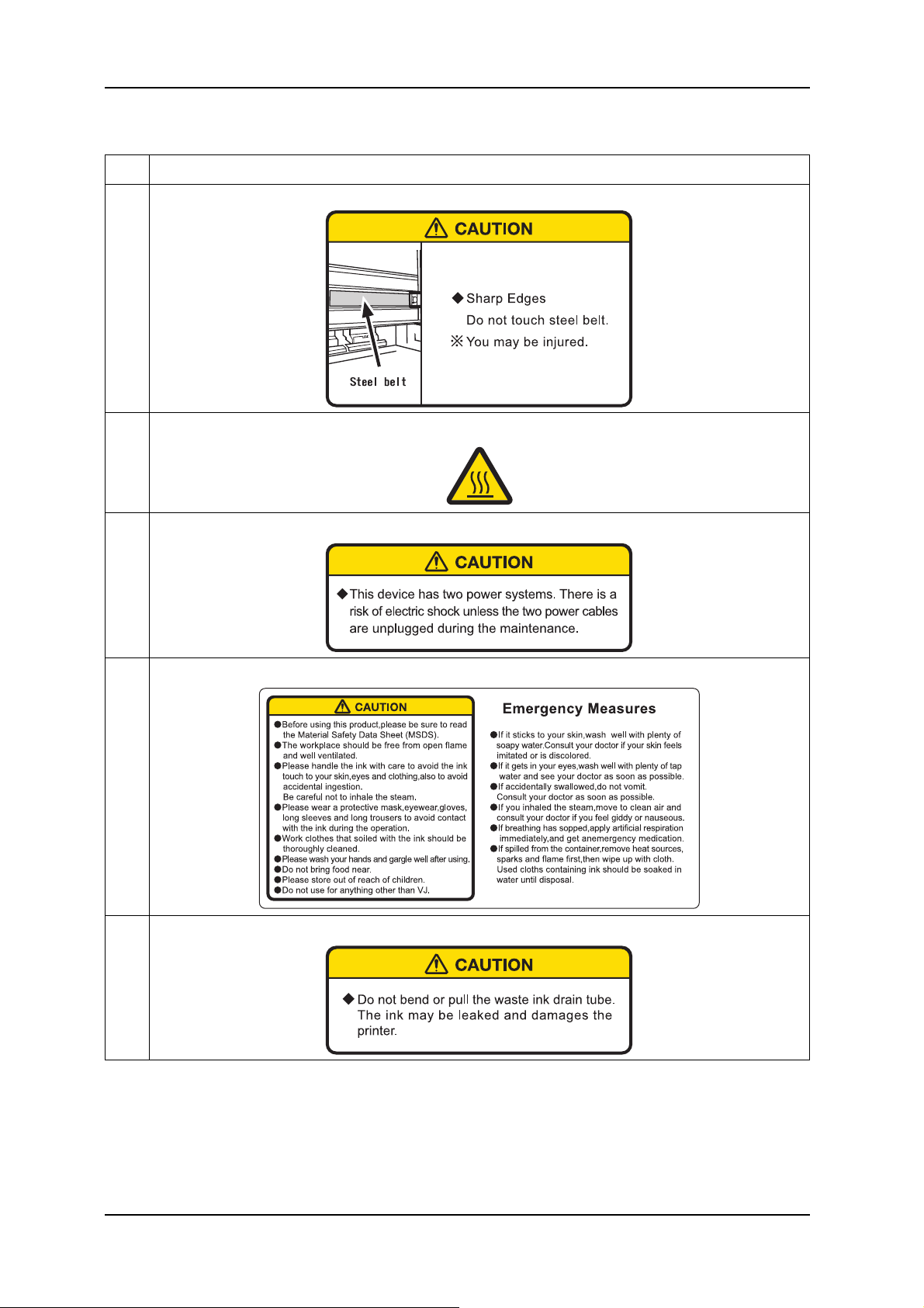
Table 1-2 List of Warning Labels
No. Warning label type
5
6
7
(Steel belt caution)
(High temperature caution)
(Electric shock caution)
8
9
(Ink handling caution)
(Waste fluid tube handling caution)
Rev.-00 1-8
Page 23
VJ-1604 Maintenance Manual 1 Safety Instructions
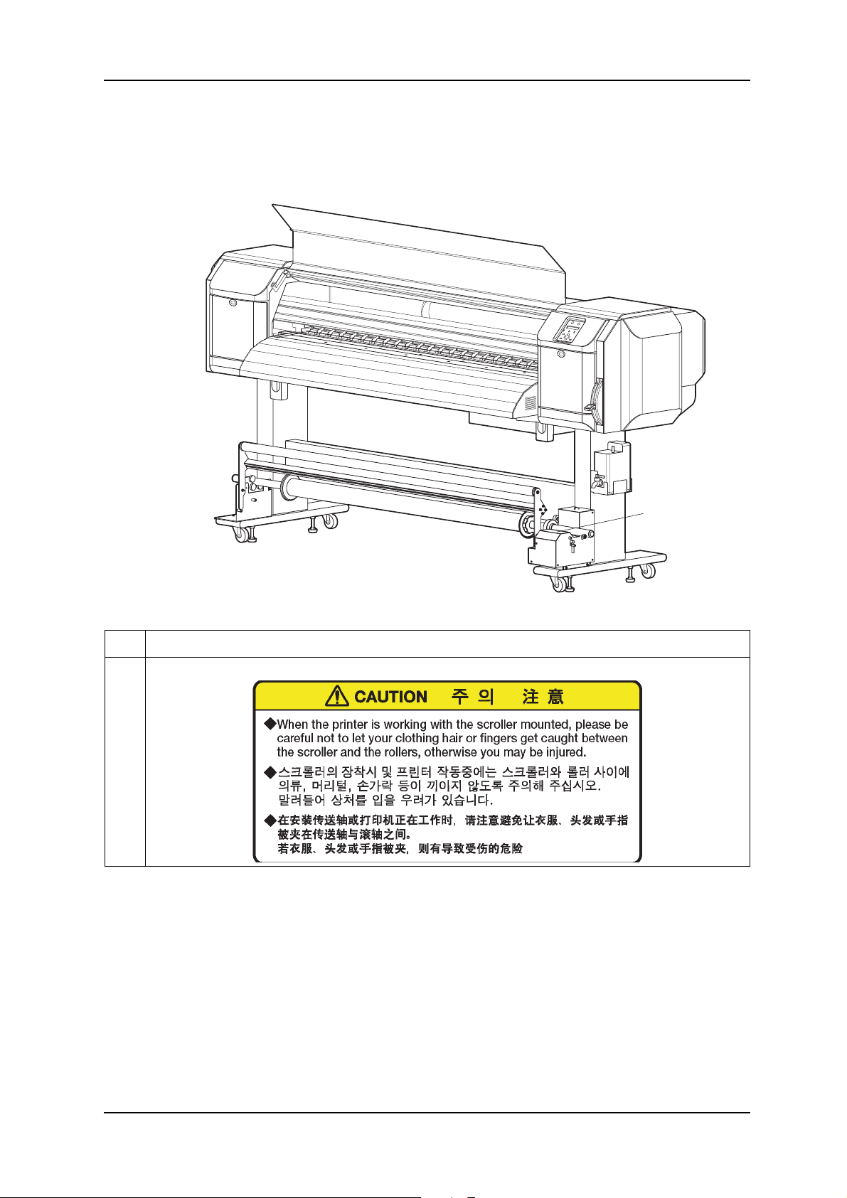
(2) Scroller (Optional)
The locations of warning labels on the scroller are shown below.
No. Warning label type
1
(Catching caution)
1
1-9 Rev.-00
Page 24

1 Safety Instructions VJ-1604 Maintenance Manual
Rev.-00 1-10
Page 25

VJ-1604 Maintenance Manual 2 Product Overview
2 Product Overview
2.1 Introduction ............................................................................................. 2- 2
2.2 Features ................................................................................................... 2- 2
2.3 Part Names and Functions..................................................................... 2- 3
2.3.1 Front Section ................................................................................. 2-4
2.3.2 Rear Section .................................................................................. 2-5
2.3.3 Scroller Section (Optional)............................................................. 2-6
2.3.4 Operation Panel............................................................................. 2-7
2.4 Plotter Status......................................................................................... 2- 10
2.4.1 Normal ......................................................................................... 2-10
2.4.2 Setup Menu ................................................................................. 2-10
2.4.3 Self-Diagnosis Function............................................................... 2-10
2.4.4 Maintenance Mode ...................................................................... 2-10
2-1 Rev.-00
Page 26

2 Product Overview VJ-1604 Maintenance Manual
2.1 Introduction
This chapter explains the features, part names, and functions of the plotter.
2.2 Features
The features of the plotter are explained below.
(1) Fast Print
This model uses the new head prints images faster.
Realizing printing width of 1615 mm in uni-direction printing mode.
(2) Variety of Print Media
The height of the print head position can be set high/low, so that this model can print on the media of which
thickness is between 0.08 and 0.3 mm.
(3) Vivid Color Reproduction
For Vivid color reproduction, this model has high-capacity (220 ml) 4 color ink cartridges with exclusive
smart IC chip on it. With the IC chip, you can manage the ink level of the cartridges and can get better
productivity.
Also, With variable dot mechanism, this model enhances the level of color expression.
(4) Multi-Heater System
The media-heating system which have been equipped to PJ series is changed to match the solvent ink. There
are 3 heaters on Pre / Platen / After positions and improved the ink fixability and drying property.
(5) Effective Utilization of Media
The JOG function for setting print start position on purpose is equipped. You can print on the margin(s) of a
media which is already printed.
(6) RIP
Special software RIP is sold for options.
Rev.-00 2-2
Page 27
VJ-1604 Maintenance Manual 2 Product Overview
NOTE
U
2.3 Part Names and Functions
Part names and functions are explained below.
For the directions described in this document, refer to the following figure.
pper
Left
Front
Rear
Right
Lower
2-3 Rev.-00
Page 28
2 Product Overview VJ-1604 Maintenance Manual
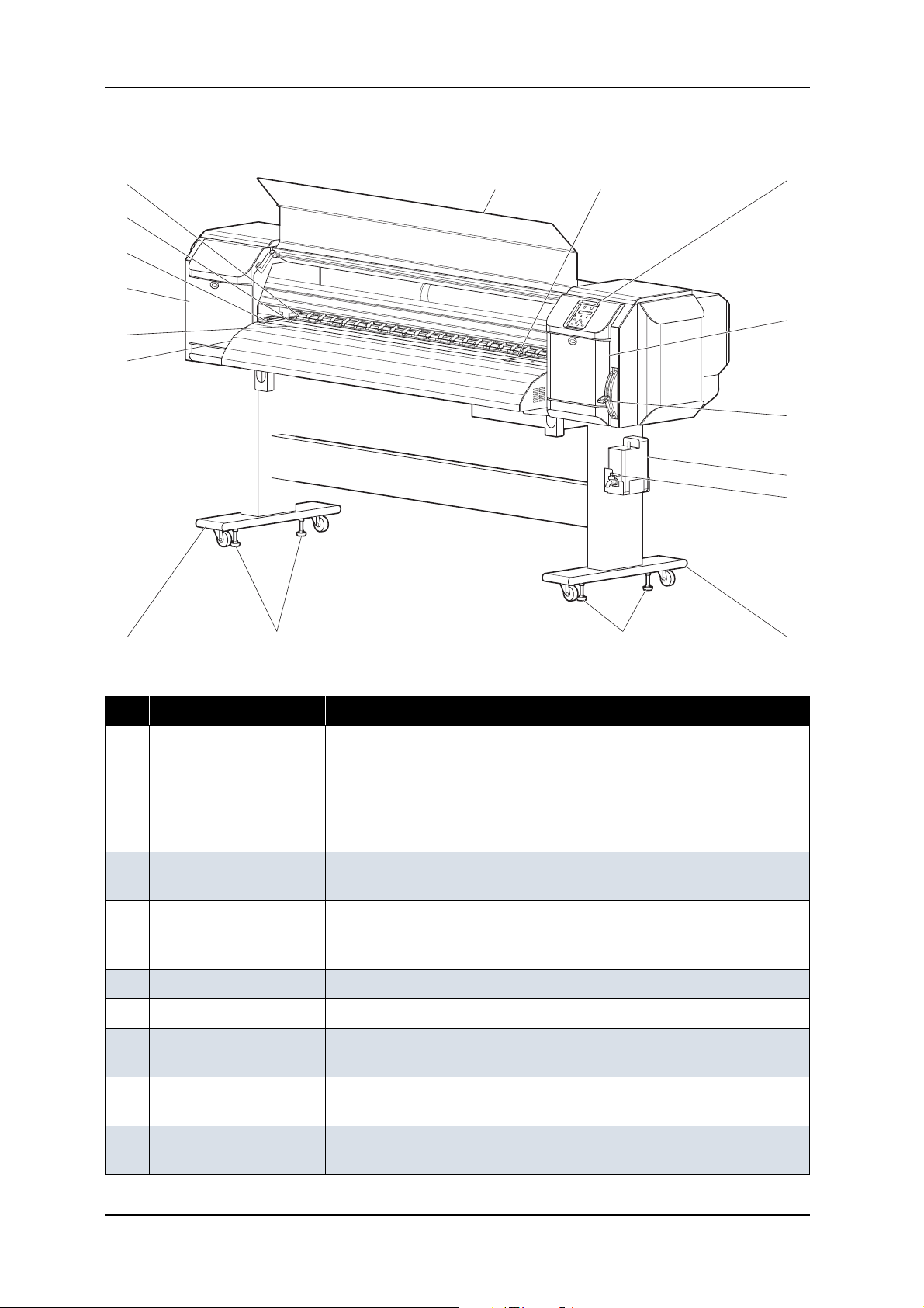
2.3.1 Front Section
13
10
8
7
9
6
133
2
10
1
4
11
5
12
12
Table 2-1 Part Names and Functions of Front Section
No. Name Function
1 Media set lever Used for fixing or releasing the media
• Lower the lever to fix the media
• Lower the lever further to fix the media firmly
Used to improve the accuracy of media feeding
* The accuracy of media feeding may decline depending on media.
• Raise the lever to release the media
2 Operation panel Used to set operational conditions, the status of the plotter, and other
functions
3 Front cover Keeps the operator safe from the drive parts of the plotter while it is
operating. Opened and closed when media is set or jammed. It is normally
closed.
4 Waste fluid tank Used to store waste ink discharged from print head
5 Stand Used to set the plotter on the level surface of the floor
6 Media Guide Used to feed media smoothly when setting media and printing
The heater (after-heater) for drying ink is installed inside.
5
7 Platen Installed inside the front cover
The heater (platen heater) for drying ink is installed.
8 Pressure roller Installed inside the front cover
Used to press the media from above and hold it when printing
Rev.-00 2-4
Page 29
VJ-1604 Maintenance Manual 2 Product Overview
Table 2-1 Part Names and Functions of Front Section (Continued)
No. Name Function
9 Media cut groove Installed inside of the front cover
Used to cut printed media straight
10 Maintenance cover Used to protect users from the mechanical parts inside the plotter in the
following cases:
- Cleaning the cleaning wiper
- Cleaning around the print head
This cover must usually be closed.
11 Waste fluid cock Opened/closed when discharging waste fluid from waste fluid tank. This
cover must usually be closed.
12 Adjuster Used to keep the plotter level
13 Media holding plate Installed inside the front cover
By attaching media holder plates to both sides of the media, it is possible
to prevent media warp.
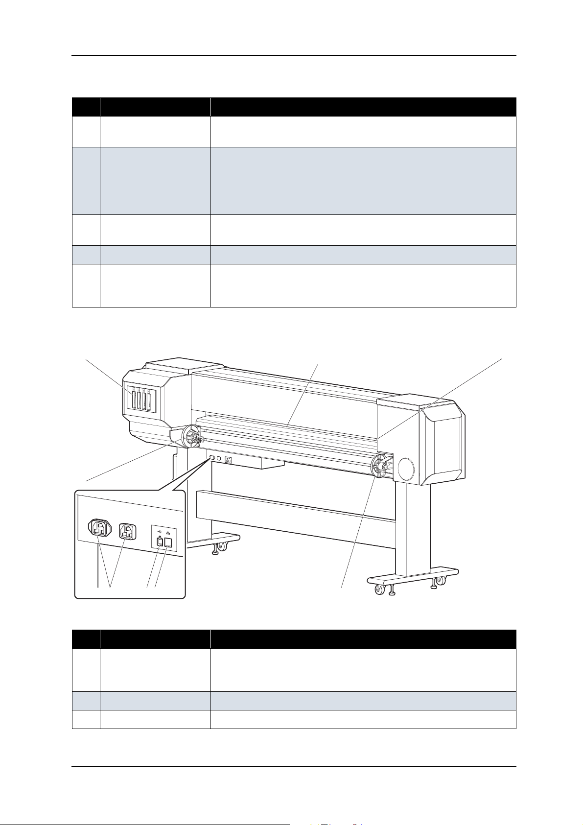
2.3.2 Rear Section
3
1
5 6 7 1
24
Table 2-2 Part Names and Functions of Rear Section
No. Name Function
1 Roll media holders Used to load the roll media
Include flanges where roll media is attached, and the levers that fix the roll
media holders.
2 Media feed slot Insert media from here when feeding media
3 Ink cartridge slot Holds the ink cartridge
2-5 Rev.-00
Page 30

2 Product Overview VJ-1604 Maintenance Manual
Table 2-2 Part Names and Functions of Rear Section (Continued)
No. Name Function
4 Media guide Used for feeding media smoothly when the media is set or printed.
The heater (pre-heater) to warm media is installed.
5 AC inlet Used for connecting the power cable
6 USB connector Not used for this printer
7 Network interface
Connector to connect a network interface cable
connector
2.3.3 Scroller Section (Optional)
6
2
8
5
3
1
Table 2-3 Part Names and Functions of Scroller Section
4
7
No. Name Function
1 Take-up device Used to take up printed media
2 Absorbing roller Used to guide printed media to the scroller
3 Scroller receiver Set the scroller for the take-up device here
4 Scroller release lever Used to poise the scroller when rotating the scroller manually
5 Scroller Used to take up printed media
6 Scroller height
Adjusts the height of scroller receiver
adjustment screw
Rev.-00 2-6
Page 31

VJ-1604 Maintenance Manual 2 Product Overview
Table 2-3 Part Names and Functions of Scroller Section (Continued)
No. Name Function
7 Scroller horizontal
Adjusts the horizontal position of the scroller
position adjustment
screw
8 Power switch Turns the plotter on/off
2.3.4 Operation Panel
The operation panel is used to set operational conditions, display the status of the plotter, and set other
functions.
The names and functions of the operation keys and status lamps are explained below.
TIP
Operation manual
8, 9
10
13
14
11
12
17
15
16
6
1
3
4
5
27
2-7 Rev.-00
Page 32

2 Product Overview VJ-1604 Maintenance Manual
NOTE
(1) Operation Keys
Some keys have multiple functions and names depending on the plotter status (normal or setup menu
display). See "2.4 Plotter Status" p.2-10 for more details.
No. Name Normal Setup menu display
1
[Menu] key
2 [Enter] key - - Selects the menu to be set and shifts
[Cleaning] key If held down for 2 seconds or more,
3 [Cancel] key - During plotting: Terminates printing
4 [<] key -Changes the setting value in the
[Nozzle Check] key If held down for 2 seconds or more,
Changes the LCD monitor display to
setup menu status.
starts cleaning the plotter head.
forcibly and deletes 1 file of
remaining data.
- During reception/analysis: Deletes
the data that has been already
received/analyzed and ignores 1 file
of data received after that.
-
starts checking the plotter nozzle.
Changes the setup menu display
status to normal status.
to the next hierarchy.
- Determines and saves the parameter
value.
-
- Returns to the previous menu
hierarchy. Changed parameter values
are disabled.
- Changes the setup menu display
status to normal status.
following menu:
• Origin setting menu
-
5 [>] key Sets the cleaning mode.
- The lamp for the cleaning mode
lights on (green).
6 [Backward ↑] key Feeds the media in the reverse
direction.
[+] key - -Changes the menu in forward order.
7[Forward
[-] key - - Changes the menu in the reverse
Rev.-00 2-8
↓] key Feeds the media in the forward
direction.
Displays lower rank menu items.
-
-Changes the setting value in forward
order.
-Increases the value when inputting
setting value.
-
direction.
- Decreases the value when inputting
values.
Page 33

VJ-1604 Maintenance Manual 2 Product Overview
No. Name Normal Setup menu display
8 [Power] key Turns the plotter on and off. Turns the plotter on and off.
(2) LCD Monitor and Status Lamps
No. Name Color Status Function
9 Power lamp Green On The plotter is switched on.
Blinking An error has occurred. The contents will be displayed on the
LCD monitor.
Off The plotter is switched off.
10 Data lamp Orange On - The plotter is analyzing received data.
- The plotter is printing data.
Blinking The plotter is receiving data.
Off The plotter is not receiving, analyzing or printing data.
11 High lamp Green On The print head height is set to High position.
Off The print head height is set to Low position.
12 Low lamp Green On The print head height is set to Low position.
Off The print head height is set to High position.
13 Wave lamp Green On The effect menu is set to Wave.
Off The effect menu is set to None.
14 Fine & S.Fine
lamp
15 Strong lamp Green On - The cleaning mode is set to Strong.
16 Normal lamp Green On - The cleaning mode is set to Normal.
17 LCD monitor - - This monitor displays the operation status and error
Green On The effect menu is set to either Fine or SuperFine.
Off The effect menu is set to Wave.
- When the Normal lamp is also on, the cleaning mode is set
to Economy.
Off - The effect menu is set to Wave.
- When the Wave lamp is also off, the effect menu is set to
None.
- When the Strong lamp is also on, the cleaning mode is set
to Economy quality.
Off The cleaning mode is set to Strong.
messages of the plotter.
TIP
When an error that requires plotter to restart (i.e. crucial failure for opration), all the lamps blinks with
alarm sound.
2-9 Rev.-00
Page 34

2 Product Overview VJ-1604 Maintenance Manual
2.4 Plotter Status
The status of the plotter is explained below.
2.4.1 Normal
Indicates that the plotter can print when media is loaded.
Each setup concerning printing can be operated by using operation panel.
TIP
Operation manual
2.4.2 Setup Menu
Each setup concerning printing can be operated by using operation panel.
The settings required for normal printing are usually made on the plotter driver or application, but can also
be made using the operation panel.
TIP
Operation manual
2.4.3 Self-Diagnosis Function
Indicates that each settings concerning printing using the operation panel. Names and functions of the
operation panel keys are the same as those of setup menu display.
TIP
"5 Self-Diagnosis Mode" p.5-1
2.4.4 Maintenance Mode
Indicates that each setup concerning to the life counter on this plotter can be operated by using the operation
panel. Names and functions of the operation panel keys are the same as those of setup menu display.
TIP
"6 Maintenance Mode 2" p.6-1
Rev.-00 2-10
Page 35

VJ-1604 Maintenance Manual 3 Specifications
3 Specifications
3.1 Introduction ............................................................................................. 3- 2
3.2 Product Specifications ........................................................................... 3- 2
3.3 Interface Specifications.......................................................................... 3- 4
3.3.1 Network Interface Specifications.................................................... 3-4
3.4 Options/Supplies List ............................................................................. 3- 4
3.4.1 Options .......................................................................................... 3-4
3.4.2 Supplies ......................................................................................... 3-4
3.5 Choosing a Place for the Printer .......................................................... 3- 6
3-1 Rev.-00
Page 36

3 Specifications VJ-1604 Maintenance Manual
3.1 Introduction
This chapter explains the specifications of the product, optional parts, and supplies. Installation environment
requirements are also explained.
3.2 Product Specifications
(1) Main Unit Specifications
Item Specifications
Model name
Plotting method
Motor driving method
Media feeding method
Media fixing method
Media supply and
Roll media
ejection
Roll media outer diameter
Roll media weight
Maximum media length
Maximum media width
Maximum media thickness
Maximum plot length
Maximum plot width
Plotting margins
Media cutting method
VJ-1604
On-demand piezo drive
Firmware servo / DC motor drive
Multi-point pressure grid roller method
Pressurizing roller manual-down method
Rear feeding / front ejection
150 mm (5.9 in.) or less
30 kg (66 lb.) or less
50 m (164 ft.)
1625 mm (63.9 in.)
0.3 mm (0.01 in.)
18 m (59.1 ft.)
1615 mm (63.6 in.)
Top: 15 mm, Bottom: 5 mm, Left: 5-25 mm, Right: 5-25 mm
Horizontal manual cut
Head height adjustment
2 levels: Normal / High
Distance accuracy The larger value either ± 0.25 mm or ± 0.1% of moving distance
•Used media: Roll MF-3G
• Plot length: 1219 mm (4 ft.)
• Operating temperature: 22 to 30ºC (71.6 to 86F)
• Operating humidity: 40 to 60%
•PG: Low
• Plot mode: Graphics1
Right angle accuracy ±0.1mm or less against the moving distance (500.0mm)
•Used media: Roll MF-3G
• Operating temperature: 22 to 30ºC (71.6 to 86F)
• Operating humidity: 40 to 60%
• Plot mode: Graphics1
CPU
Memory
Rev.-00 3-2
64Bit RISC CPU
256MB
Page 37

VJ-1604 Maintenance Manual 3 Specifications
Item Specifications
Command
Interface
Ink Supply method
Cartridge
Network Interface (Ethernet IEEE802.3)
Tube supply from four separate cartridges
Black, cyan, magenta, yellow: 220ml ± 5ml for each color
MH-RTL (RTL-PASS)
Environmental conditions Temperature Humidity
Operation environment
Plotting accuracy warranty range
Rate of change
Storage
environment
Without ink
With ink
Power source Voltage
Frequency
Power
consumption
During Plotting
During standby
Outer dimensions Height
Width
20ºC (68F) to 30ºC (86F) 40% to 60%, with no condensation
22ºC (71.6F) to 30ºC (86F) 40% to 60%, with no condensation
2ºC/hour or less 5%/hour or less
-20ºC (-4F) to 60ºC (140F) 20% to 80%, with no condensation
-10ºC (14F) to 40ºC (104F) 20% to 80%, with no condensation
AC 90 - 132V
50Hz / 60Hz ± 1Hz
1200W (when heater is ON)
40W or less (when standby heater is OFF)
1262mm (49.7 in.) * including dedicated stand
2698 mm (106in.)
Weight
Depth
845 mm (33.3 in.)
173 kg (380.6 lb.)
3-3 Rev.-00
Page 38

3 Specifications VJ-1604 Maintenance Manual
3.3 Interface Specifications
This section explains the specification of the interfaces Supported for this printer.
3.3.1 Network Interface Specifications
Item Specifications
Network type Ethernet IEEE802.3
Network I/F 10BASE-T / 100BASE-TX Auto-switching
(RJ-45 connector twist pair cable)
MDI / MDI-X Auto-switching
Corresponding
protocol
TCP/IP
3.4 Options/Supplies List
3.4.1 Options
TIP
For more information about the take-up device (optional), contact the following.
• MUTOH distributor
• MUTOH sales office
3.4.2 Supplies
(1) Ink Cartridge
Name Model Sales units
Ink cartridge K (Black: 220 ml
Ink cartridge C (Cyan: 220 ml
Ink cartridge M (Magenta: 220 ml
Ink cartridge Y (Yellow: 220 ml
Cleaning cartridge (220 ml
Rev.-00 3-4
± 5 ml)
± 5 ml)
± 5 ml)
± 5 ml)
± 5 ml)
VJ-MSINK3-MA220
VJ-MSINK3-BK220
VJ-MSINK3-CY220
VJ-MSINK3-YE220
VJ-MSINK3-CL220
1 box (1 piece per box)
1 box (1 piece per box)
1 box (1 piece per box)
1 box (1 piece per box)
1 box (1 piece per box)
Page 39

VJ-1604 Maintenance Manual 3 Specifications
(2) Other Supplies
Name Model Sales units
Waste ink bottle
RJ8000-HET
1 box (1 piece per box)
3-5 Rev.-00
Page 40

3 Specifications VJ-1604 Maintenance Manual
3.5 Choosing a Place for the Printer
WARNING
• Do not place the printer in a location under the following conditions. Doing so may cause
the product to fall, become damaged, or cause injury.
• Unstable surfaces
• Slanted areas
• Locations that are subject to vibration from other product
• Do not stand on the printer or place any heavy objects on it.
Doing so may cause it to fall over, become damaged, or cause injury.
• Do not cover the ventilation hole of the printer with cloth, such as a blanket or table cloth.
Doing so could prevent the printer from ventilating and cause fire.
• Keep the printer away from humid and dusty areas. Failure to do so may result in
electrical shock or fire.
(1) Installation Environment Requirements
Choose a place for printer installation following the requirements of the table below.
Table 3-1 Installation Environment Requirements List
Floor loading capability 2940Pa (300kgf/m
Electrical
specification
s
Environmental conditions Temperature Humidity
Voltage AC 90-132 V
Frequency 50/60Hz ± 1Hz
Capacity Main side: 8.5 A, Heater side: 8.5A
Operation
environment
Plotting accuracy
warranty range
Rate of change 2ºC/hour or less 5%/hour or less
Storage
environment
20º C (68F) - 32ºC (86F) 40% - 60%, with no condensation
22ºC (71.6F) - 30ºC (86F) 40% - 60%, with no condensation
-20ºC - 60ºC 20% - 80%
2
) or over
No condensation (when ink is not
charged)
Rev.-00 3-6
Page 41

VJ-1604 Maintenance Manual 3 Specifications
NOTE
NOTE
• Avoid the following temperature and humidity conditions. Otherwise, Plotted images may appear
differently from what you expect.
• Places where sudden changes in temperature and humidity are expected, even though the
condition is within the range specified
• Places where direct sunlight or excessive lighting are expected
• Places where air conditioners blow directly
• MUTOH recommends that the printer should be installed where air conditioning can be adjusted
easily.
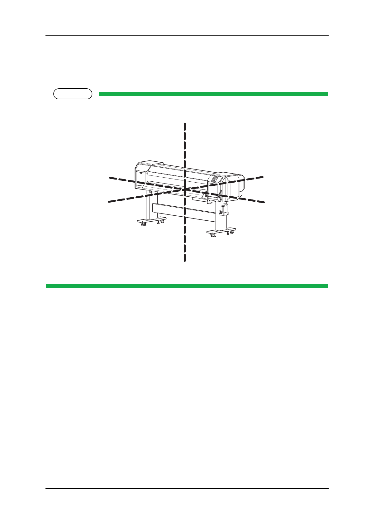
(2) Required Space
Install the printer on a flat surface that fulfills the following conditions.
• The place to install printer with the optional stand should have enough loading capacity.
For the printer and the optional stand, refer to"3.2 Product Specifications" p.3-2.
a= 600 mm
b=1000 mm
c=1000 mm
d=1000 mm
e=1550 mm
e
a
d
b
c
* Do not use VJ-1604 without stand.
3-7 Rev.-00
Page 42

3 Specifications VJ-1604 Maintenance Manual
Rev.-00 3-8
Page 43

VJ-1604 Maintenance Manual 4 Parts Replacement
4 Parts Replacement
4.1 Introduction ............................................................................................. 4- 6
4.2 Removing Covers ................................................................................... 4- 7
4.2.1 Removing Panel Cover.................................................................. 4-9
4.2.2 Removing Maintenance Cover....................................................... 4-9
4.2.3 Removing Maintenance Cover U................................................. 4-10
4.2.4 Removing Side Maintenance Cover R......................................... 4-11
4.2.5 Removing Side Maintenance Cover L ......................................... 4-12
4.2.6 Removing Side Top Cover R ....................................................... 4-12
4.2.7 Removing Side Top Cover L........................................................ 4-14
4.2.8 Removing Rear Side Cover ......................................................... 4-15
4.2.9 Removing Cartridge Cover (Upper) ............................................. 4-17
4.2.10 Removing Cartridge Cover (middle) ............................................ 4-18
4.2.11 Removing Cartridge Cover (lower) .............................................. 4-19
4.2.12 Removing Switch Cover R ........................................................... 4-19
4.2.13 Removing Switch Cover L............................................................ 4-20
4.2.14 Removing Front Cover................................................................. 4-21
4.2.15 Removing Rear Top Cover .......................................................... 4-21
4.2.16 Removing Top Cover ................................................................... 4-23
4.2.17 Removing Media Guide F (Upper) ............................................... 4-24
4.2.18 Removing Media Guide R (Upper)............................................... 4-27
4.2.19 Removing Media Guide R (Lower)............................................... 4-29
4.3 Replacing Covers.................................................................................. 4- 30
4.3.1 Replacing Panel Unit ................................................................... 4-30
4-1 Rev.-00
Page 44

4 Parts Replacement VJ-1604 Maintenance Manual
4.3.2 Replacing Maintenance Cover Sensor......................................... 4-31
4.3.3 Replacing Front Cover Sensor ..................................................... 4-32
4.3.4 Replacing Front Cover Gear, Damper Gear (Sintered) ................ 4-35
4.4 Replacing Board Base (X Rail Section) ...............................................4- 39
4.4.1 Opening Board Box 64 ................................................................. 4-40
4.4.2 Replacing Power Board Assembly ............................................... 4-41
4.4.3 Replacing HEATER CONT Board ................................................ 4-42
4.4.4 Replacing HEATER RELAY Board............................................... 4-44
4.4.5 Replacing Cooling Fan (24V) Assembly (for Main Board)............ 4-46
4.4.6 Replacing Cooling Fan (24V) Assembly (in Media Guide F) ........ 4-48
4.4.7 Replacing MAIN Board................................................................. 4-49
4.4.8 Replacing Fuse............................................................................. 4-53
4.4.9 Replacing Inlet Assembly ............................................................. 4-55
4.5 Replacing Board Base Section (Y Rail Section) .................................4- 58
4.5.1 Replacing Heater Junction Board Assembly ................................ 4-58
4.6 Replacing X Rail Section ......................................................................4- 60
4.6.1 Replacing PF Speed Reduction Belt ............................................ 4-60
4.6.2 Replacing PF Motor Assembly ..................................................... 4-61
4.6.3 Replacing PF Encoder Assembly................................................. 4-63
4.6.4 Replacing PF_ENC Scale, PF Speed Reduction Pulley .............. 4-64
4.6.5 Replacing P_REAR Sensor Assembly ......................................... 4-65
4.6.6 Replacing Lever Up Sensor.......................................................... 4-67
4.6.7 Replacing Heater, Thermistor....................................................... 4-68
4.6.8 Replacing Suction Fan ................................................................. 4-76
Rev.-00 4-2
Page 45

VJ-1604 Maintenance Manual 4 Parts Replacement
4.6.9 Replacing Platen Non-Reflective Tape........................................ 4-77
4.6.10 Replacing Media Holder............................................................... 4-78
4.6.11 Replacing Flushing Tray .............................................................. 4-80
4.6.12 Replacing Flushing Absorber....................................................... 4-82
4.7 Replacing Y Rail Section...................................................................... 4- 84
4.7.1 Replacing Steel Belt..................................................................... 4-84
4.7.2 Replacing CR Motor Assembly.................................................... 4-87
4.7.3 Replacing CR Drive Pulley Assembly.......................................... 4-89
4.7.4 Replacing T Fence....................................................................... 4-91
4.7.5 Replacing CR Origin Sensor........................................................ 4-94
4.7.6 Replacing CR Driven Pulley......................................................... 4-96
4.7.7 Replacing Steel Bearer................................................................ 4-97
4.7.8 Replacing CR Tape Wire ............................................................. 4-99
4.7.9 Replacing Pressure Roller ......................................................... 4-101
4.7.10 Replacing Ink Tube .................................................................... 4-102
4.8 Replacing Cursor Section .................................................................. 4- 105
4.8.1 Releasing Head Lock................................................................. 4-105
4.8.2 Removing CR Board Cover ....................................................... 4-106
4.8.3 Replacing CR Board Assembly.................................................. 4-106
4.8.4 Replacing CR Encoder Assembly.............................................. 4-108
4.8.5 Replacing PG Origin Sensor Assembly ..................................... 4-109
4.8.6 Replacing Cursor Roller Arm Assembly..................................... 4-110
4.8.7 Removing Print Head Cover ...................................................... 4-110
4.8.8 Replacing Damper Assembly L_Assy........................................ 4-112
4-3 Rev.-00
Page 46

4 Parts Replacement VJ-1604 Maintenance Manual
4.8.9 Replacing Print Head.................................................................. 4-114
4.8.10 Replacing Head FFC .................................................................. 4-116
4.8.11 Replacing P_EDGE Sensor Assembly ....................................... 4-118
4.9 Replacing Maintenance Section.........................................................4- 120
4.9.1 Removing Maintenance Inner Cover .......................................... 4-120
4.9.2 Replacing Cleaner Head ............................................................ 4-121
4.9.3 Replacing Maintenance Assembly ............................................. 4-122
4.10 Replacing IH Section...........................................................................4- 125
4.10.1 Replacing Ink ID Board Assembly .............................................. 4-125
4.10.2 Replacing Frame Assembly, Needle .......................................... 4-128
4.10.3 Replacing Ink Cartridge Control Cable ....................................... 4-132
4.10.4 Replacing Cartridge Holder Assembly........................................ 4-132
4.10.5 Replacing two-way Valve ........................................................... 4-133
4.10.6 Replacing Sub-Tank Lower Absorber Assembly ........................ 4-135
4.11 Replacing Leg Section ........................................................................4- 136
4.11.1 Replacing Waste Fluid Bottle ..................................................... 4-136
4.12 Replacing Roll Media Holder Assembly ............................................4- 138
4.12.1 Replacing Roll Media Holder Assembly on the VJ16_L side...... 4-138
4.12.2 Replacing Roll Media Holder Assembly on the VJ16_R side ..... 4-139
4.13 Replacing Take-up Section.................................................................4- 140
4.13.1 Removing Take-up Cover........................................................... 4-140
4.13.2 Replacing Scroller ...................................................................... 4-141
4.13.3 Replacing VJ Take-up CNT Board Assembly............................. 4-143
4.13.4 Replacing CR_HP Sensor, Lever Sensor................................... 4-150
Rev.-00 4-4
Page 47

VJ-1604 Maintenance Manual 4 Parts Replacement
4.13.5 Replacing Peripheral Devices of VJ Take-up Motor Assembly.. 4-153
4-5 Rev.-00
Page 48

4 Parts Replacement VJ-1604 Maintenance Manual
NOTE
4.1 Introduction
This chapter provides information on removal and replacement of service parts.
WARNING
• Before starting part replacement, always perform the following operations.
• Turn OFF the machine power.
• Remove the power plug from the outlet.
Otherwise, you may suffer electric shock or the system circuit may be damaged.
• Remove any cables connected to the plotter.
Otherwise, the plotter may be damaged.
CAUTION
The components in the plotter can be disassembled only if so instructed in this manual. Do
not disassemble the frame components and other components that are not instructed to
disassemble in the manual.
The plotter has been assembled in the MUTOH factory with extremely high precision up to
1/100mm. If disassembled inappropriately, it may not restore its normal functionality.
After replacing any service parts, perform necessary lubrication and bonding following the
instructions in section "8.5 Lubrication/Bonding" p.8-7.
Rev.-00 4-6
Page 49

VJ-1604 Maintenance Manual 4 Parts Replacement
4.2 Removing Covers
This section describes the procedures to replace covers.
11
8
6
7
5
17
16
10
5
1
4
2
3
12
13
19
18
8
15
13
9
14
20
21
Table 4-1 Cover Component List
No. Part name
1 Panel cover
2 Maintenance cover R
3 Maintenance cover U_R
4 Side maintenance cover R
4-7 Rev.-00
Page 50

4 Parts Replacement VJ-1604 Maintenance Manual
Table 4-1 Cover Component List (Continued)
No. Part name
5 Side top cover R
6 Maintenance cover L
7 Maintenance cover U_L
8 Side top cover L
9 Side maintenance cover L
10 Front cover
11 Acrylic plate
12 Media guide F (upper)
13 Board box 64
14 Rear side cover
15 Cartridge cover (lower)
16 Cartridge cover (middle)
17 Cartridge cover (upper)
18 Rear top cover
19 Top cover
20 Media guide R (upper)
21 Media guide R (lower)
Rev.-00 4-8
Page 51

VJ-1604 Maintenance Manual 4 Parts Replacement
NOTE
4.2.1 Removing Panel Cover
1. Open the maintenance cover R.
2. Remove the screws (2 pieces) that retain the panel cover.
1
2
No. Part name
1 Panel cover
2 Screws that retain the panel cover
(pan-head screw with spring washer and flat washer M4 × 8)
3. Remove the panel cover.
4. To reassemble the unit, reverse the removal procedure.
2
4.2.2 Removing Maintenance Cover
The procedure to remove the maintenance cover R is the same as the one for the maintenance cover L.
1. Open the maintenance cover.
2. Lift up the maintenance cover.
3. Remove the maintenance cover.
4-9 Rev.-00
Page 52

4 Parts Replacement VJ-1604 Maintenance Manual
NOTE
1
No. Part name
1 Maintenance cover
4. To reassemble the unit, reverse the removal procedure.
4.2.3 Removing Maintenance Cover U
The procedure to remove the maintenance cover U_R is the same as the one for the maintenance
cover U_L.
1. Remove the maintenance cover.
"4.2.2 Removing Maintenance Cover" p.4-9
Rev.-00 4-10
Page 53

VJ-1604 Maintenance Manual 4 Parts Replacement
2. Remove the screws (2 pieces) that retain the maintenance cover U.
2
1
No. Part name
1 Maintenance cover U
2 Screws that retain the maintenance cover U
(pan-head screw with spring washer and flat washer M4 × 8)
3. Remove the Maintenance cover U.
4. To reassemble the unit, reverse the removal procedure.
4.2.4 Removing Side Maintenance Cover R
1. Remove the screws (2 pieces) that retain the side maintenance cover R.
1
No. Part name
1 Side maintenance cover R
2 screws that retain the side maintenance cover R
(pan-head screw with spring washer and flat washer M4
4-11 Rev.-00
2
× 8)
Page 54

4 Parts Replacement VJ-1604 Maintenance Manual
NOTE
2. Lift up and remove the side maintenance cover R.
3. To reassemble the unit, reverse the removal procedure.
4.2.5 Removing Side Maintenance Cover L
1. Remove the screws (2 pieces) that retain the side maintenance cover L.
1
No. Part name
1 Side maintenance cover L
2 Screws that retain the side maintenance cover L
(pan-head screw with spring washer and flat washer M4
2. Lift up and remove the side maintenance cover L.
3. To reassemble the unit, reverse the removal procedure.
4.2.6 Removing Side Top Cover R
Before removing the side top cover R, close the front cover.
1. Remove the side maintenance cover R.
"4.2.4 Removing Side Maintenance Cover R" p.4-11
2
× 8)
Rev.-00 4-12
Page 55

VJ-1604 Maintenance Manual 4 Parts Replacement
2. Remove the screws (2 pieces) that retain the side top cover R.
2
No. Part name
1Side top cover R
2 Screws that retain the side top cover R
(pan-head screw with spring washer and flat washer M4
3. Remove the side top cover R to the direction shown in the picture below.
1
× 8)
4. To reassemble the unit, reverse the removal procedure.
4-13 Rev.-00
Page 56

4 Parts Replacement VJ-1604 Maintenance Manual
NOTE
4.2.7 Removing Side Top Cover L
Before removing the side top cover L, close the front cover.
1. Remove the side maintenance cover L.
"4.2.5 Removing Side Maintenance Cover L" p.4-12
2. Remove the screws (2 pieces) that retain the side top cover L.
2
No. Part name
1 Side top cover L
2 Screws that retain the side top cover L
(pan-head screw with spring washer and flat washer M4
3. Remove the side top cover L to the direction shown in the picture below.
1
× 8)
4. To reassemble the unit, reverse the removal procedure.
Rev.-00 4-14
Page 57

VJ-1604 Maintenance Manual 4 Parts Replacement
4.2.8 Removing Rear Side Cover
1. Remove the side maintenance cover L.
"4.2.5 Removing Side Maintenance Cover L" p.4-12
2. Remove the side top cover L.
"4.2.7 Removing Side Top Cover L" p.4-14
3. Remove the screws (2 pieces) that retain the rear side cover 3.
1
No. Part name
1 Rear side cover 3
2 Screws that retain the rear side cover 3
(tapping screw M3
3 Rear side cover
4. Remove the rear side cover 3.
2
3
× 8)
4-15 Rev.-00
Page 58

4 Parts Replacement VJ-1604 Maintenance Manual
5. Remove the screws (2 pieces) on the lower part of the rear side cover.
1
2
No. Part name
1 Rear side cover
2 Screws that retain the rear side cover
(pan-head screw with spring washer and flat washer M4
6. Remove the screws (3 pieces) on the left and right side of the rear side cover.
Rear left view
2
1
1
Rear right view
No. Part name
1 Rear side cover
2 Screws that retain the rear side cover
(pan-head screw with spring washer and flat washer M4
× 8)
2
× 8)
Rev.-00 4-16
Page 59

VJ-1604 Maintenance Manual 4 Parts Replacement
7. Remove the rear side cover.
1
No. Part name
1 Rear side cover
8. To reassemble the unit, reverse the removal procedure.
4.2.9 Removing Cartridge Cover (Upper)
1. Remove the ink cartridge (6 pieces).
2. Remove the screws (4 pieces) that retain the left and right part of the cartridge cover (upper).
2
Rear left view
1
1
No. Part name
1 Cartridge cover (Upper)
Rear right view
2
2 Screws that retain the cartridge cover (Upper)
(pan-head screw with spring washer and flat washer M4
4-17 Rev.-00
× 8)
Page 60

4 Parts Replacement VJ-1604 Maintenance Manual
3. Remove the screws (2 pieces) on the upper part of the Cartridge cover (Upper).
2
1
No. Part name
1 Cartridge cover (upper)
2 Screws that retain the cartridge cover (upper)
(pan-head screw with spring washer and flat washer M4
4. Remove the cartridge cover (upper).
5. To reassemble the unit, reverse the removal procedure.
4.2.10 Removing Cartridge Cover (middle)
1. Remove the cartridge cover (upper).
"4.2.9 Removing Cartridge Cover (Upper)" p.4-17
2. Remove the screws (2 pieces) that retain the cartridge cover (middle).
× 8)
1
No. Part name
1 Cartridge cover (middle)
2 Screws that retain the cartridge cover (middle)
(pan-head screw with spring washer and flat washer M3
Rev.-00 4-18
2
× 8)
Page 61

VJ-1604 Maintenance Manual 4 Parts Replacement
3. Remove the cartridge cover (middle).
4.2.11 Removing Cartridge Cover (lower)
1. Remove the screws (4 pieces) that retain the cartridge cover (lower).
2
Left view
1
1
No. Part name
1 Cartridge cover (lower)
2 Screws that retain the cartridge cover (lower)
(pan-head screw with spring washer and flat washer M4
2. Remove the cartridge cover (lower).
3. To reassemble the unit, reverse the removal procedure.
Right view
× 8)
2
4.2.12 Removing Switch Cover R
1. Remove the side top cover R.
"4.2.6 Removing Side Top Cover R" p.4-12
4-19 Rev.-00
Page 62

4 Parts Replacement VJ-1604 Maintenance Manual
2. Remove the screws (3 pieces) that retain the switch cover R.
Rear view
2
1
2
No. Part name
1 Switch cover R
2 Screws that retain the switch cover R
(pan-head screw with spring washer and flat washer M3
3. Remove the switch cover R.
4. To reassemble the unit, reverse the removal procedure.
Right view
1
× 8)
4.2.13 Removing Switch Cover L
1. Remove the side top cover L.
"4.2.7 Removing Side Top Cover L" p.4-14
2. Remove the screws (3 pieces) that retain the switch cover L.
Rear view
2
No. Part name
1 Switch cover L
1
Left view
1
2
2 Screws that retain the switch cover L
(pan-head screw with spring washer and flat washer M3
Rev.-00 4-20
× 8)
Page 63

VJ-1604 Maintenance Manual 4 Parts Replacement
3. Remove the switch cover L.
4. To reassemble the unit, reverse the removal procedure.
4.2.14 Removing Front Cover
CAUTION
Front cover removal must be done by two or more persons.
1. Remove the screws that retain the left and right side of the front cover (4 pieces respectively).
Left view
2
2
No. Part name
1 Front cover
2 Screws that retain the front cover
(Trusco screw M4
× 6)
2. Remove the front cover.
3. To reassemble the unit, reverse the removal procedure.
Right view
1
4.2.15 Removing Rear Top Cover
CAUTION
Rear top cover removal must be done by 2 or more persons.
1. Remove the Side Top Cover R.
"4.2.6 Removing Side Top Cover R" p.4-12
2. Remove the Rear side cover.
"4.2.8 Removing Rear Side Cover" p.4-15
4-21 Rev.-00
Page 64

4 Parts Replacement VJ-1604 Maintenance Manual
3. Remove the Side Top Cover L.
"4.2.7 Removing Side Top Cover L" p.4-14
4. Remove the Cartridge cover (upper).
"4.2.9 Removing Cartridge Cover (Upper)" p.4-17
5. Remove the screws (5 pieces) on the back of the rear top cover.
6. Remove the screws (5 pieces) on the upper side of the rear top cover.
3
1
No. Part name
1 Rear top cover
2 Screws that retain the rear top cover
(pan-head screw with spring washer and flat washer M4
3 Screws that retain the rear top cover
(cup screw M3 × 8)
7. Remove the rear top cover.
8. To reassemble the unit, reverse the removal procedure.
2
× 8)
Rev.-00 4-22
Page 65

VJ-1604 Maintenance Manual 4 Parts Replacement
4.2.16 Removing Top Cover
CAUTION
Top cover removal must be done by 2 or more persons.
1. Remove the front cover.
"4.2.14 Removing Front Cover" p.4-21
2. Remove the rear top cover.
"4.2.15 Removing Rear Top Cover" p.4-21
3. Remove the screws (6 pieces) that retain the back of the top cover.
Rear view
2
No. Part name
1 Top cover
2 Screws that retain the top cover
(pan-head screw with spring washer and flat washer M3
1
× 8)
4-23 Rev.-00
Page 66

4 Parts Replacement VJ-1604 Maintenance Manual
4. Remove the screws (5 pieces) that retain the front of the top cover.
Front view
2
No. Part name
1 Top cover
2 Screws that retain the top cover
(pan-head screw with spring washer and flat washer M3
5. Remove the top cover.
6. To reassemble the unit, reverse the removal procedure.
1
× 8)
4.2.17 Removing Media Guide F (Upper)
CAUTION
Media guide F (upper) removal must be done by 2 or more persons.
1. Remove the maintenance cover.
"4.2.2 Removing Maintenance Cover" p.4-9
Rev.-00 4-24
Page 67

VJ-1604 Maintenance Manual 4 Parts Replacement
2. Remove the screws (2 pieces) that retain the media guide FR.
1
Right upper view
No. Part name
1 Media guide FR
2 Screws that retain the media guide FR
(pan-head screw with spring washer and flat washer M4
3. Remove the
media guide FR.
4. Remove the screws (2 pieces) that retain the media guide FL.
1
Left upper view
Lower view
Lower view
2
× 8)
2
No. Part name
1 Media guide FL
2 Screws that retain the media guide FL
(pan-head screw with spring washer and flat washer M4
5. Remove the media guide FL.
× 8)
4-25 Rev.-00
Page 68

4 Parts Replacement VJ-1604 Maintenance Manual
6. Remove the screws (5 pieces) that retain the bottom of the media guide F (upper).
2
1
No. Part name
1 Media guide F (upper)
2 Screws that retain the media guide F (upper)
(pan-head screw with spring washer and flat washer M4
7. Remove the screws (5 pieces) that retain the media guide F (upper).
1
No. Part name
1 Media guide F (upper)
2 Screws that retain the media guide F (upper)
(binding small screw M3
× 6)
× 8)
2
8. Lift up the media guide F (upper).
Rev.-00 4-26
Page 69

VJ-1604 Maintenance Manual 4 Parts Replacement
9. Remove the two connectors to the after-heater and the two connectors to the after-thermistor that are in
side the media guide F (upper).
3
1
No. Part name
1 Media guide F (upper)
2 Media guide F (lower)
3 Connector to the after-thermistor
4 Connector to the after-heater
2
4
10. Remove the media guide F (upper).
11. To reassemble the unit, reverse the removal procedure.
4.2.18 Removing Media Guide R (Upper)
CAUTION
Media guide R (upper) removal must be done by 2 or more persons.
1. Remove media.
4-27 Rev.-00
Page 70

4 Parts Replacement VJ-1604 Maintenance Manual
2. Remove the screws (4 pieces) that retain the media guide R (upper).
1
2
No. Part name
1 Media guide R (upper)
2 Screws that retain the media guide R (upper)
(pan-head screw with spring washer and flat washer M4
× 8)
3. Push backward the media guide R (upper).
4. Remove the two connectors to the pre-heater and the two connectors to the pre-thermistor that are in side
the media guide R (upper).
1
3
4
2
No. Part name
1 Rear top cover
2 Media guide R (upper)
3 Connector to the pre-thermistor
4 Connector to the pre-heater
5. Remove the media guide R (upper).
6. To reassemble the unit, reverse the removal procedure.
Rev.-00 4-28
Page 71

VJ-1604 Maintenance Manual 4 Parts Replacement
NOTE
4.2.19 Removing Media Guide R (Lower)
CAUTION
Media guide R (lower) removal must be done by 2 or more persons.
1. Remove the media guide R (upper).
"4.2.18 Removing Media Guide R (Upper)" p.4-27
If the roll media holder overlaps the screw holes, displace the roll media holder.
2. Remove the screws (8 pieces) that retain the media guide R (lower).
2
No. Part name
1 Media guide R (lower)
2 Screws that retain the media guide R (lower)
(pan-head screw with spring washer and flat washer M4
3. Remove the
4. To reassemble the unit, reverse the removal procedure.
media guide R (lower).
1
2
× 8)
4-29 Rev.-00
Page 72

4 Parts Replacement VJ-1604 Maintenance Manual
4.3 Replacing Covers
This section describes the procedures to replace the covers.
4.3.1 Replacing Panel Unit
CAUTION
• When replacing the panel unit, first pull out the AC cable.
Power may be turned on depending on how the cable is connected, and that may damage
the board.
• When connecting and removing the FFC type cables (panel tape wires), always pull or
push the cables perpendicularly.
Pulling or pushing them slantwise may damage/short/break the terminals in the
connectors, causing a breakdown of the on-board devices.
• The cables can be connected or removed up to 5 times.
1. Remove the panel cover.
"4.2.1 Removing Panel Cover" p.4-9
2. Remove the panel to conversion board tape wire.
3. Release the four panel unit back tabs (4 pieces) from the panel stay.
2
1
2
Front view
4
No. Part name
1 Panel unit
2 Panel unit tab
1
2
3
2
3
Rear view
2
3 Panel stay
4 Panel FFC
4. Remove the
5. Replace the panel unit.
6. To reassemble the unit, reverse the removal procedure.
Rev.-00 4-30
panel unit.
Page 73

VJ-1604 Maintenance Manual 4 Parts Replacement
4.3.2 Replacing Maintenance Cover Sensor
(1) Replacing Maintenance Cover Sensor R
1. Remove the maintenance cover U.
"4.2.3 Removing Maintenance Cover U" p.4-10
2. Detach the connector for the maintenance cover sensor assembly.
3. Remove the screws (2 pieces) that retain the maintenance cover sensor assembly.
2
1
No. Part name
1 Maintenance cover sensor assembly
2 Screws that retain the maintenance cover sensor assembly
(pan-head screw with spring washer and flat washer M2
3 Connector for the maintenance cover sensor assembly
4. Remove the maintenance cover sensor assembly.
5. Replace the maintenance cover sensor assembly.
6. To reassemble the unit, reverse the removal procedure.
TIP
The maintenance cover sensor looks like the following.
Opened
3
× 6)
Closed
4-31 Rev.-00
Page 74

4 Parts Replacement VJ-1604 Maintenance Manual
(2) Replacing Maintenance Cover Sensor L
The procedure to replace the maintenance cover sensor L is the same as the one for the maintenance cover
sensor R.
4.3.3 Replacing Front Cover Sensor
(1) R Side
1. Remove the Side top cover R.
"4.2.6 Removing Side Top Cover R" p.4-12
2. Remove the switch cover R.
"4.2.12 Removing Switch Cover R" p.4-19
3. Detach the connector for the cover sensor (C) assembly_R.
Rev.-00 4-32
Page 75

VJ-1604 Maintenance Manual 4 Parts Replacement
4. Remove the screws (2 pieces) that retain the cover sensor (C) assembly_R.
2
3
No. Part name
1 Cover sensor (C) assembly_R
2 Screws that retain the cover sensor (C) assembly_R
(pan-head screw with spring washer and flat washer M2
12)
3 Damper cover R
5. Remove the cover sensor (C) assembly_R.
6. To reassemble the unit, reverse the removal procedure.
TIP
The cover sensor looks like the following.
Opened
1
×
Closed
(2) L Side
1. Remove the Side top cover L.
"4.2.7 Removing Side Top Cover L" p.4-14
2. Remove the switch cover L.
"4.2.13 Removing Switch Cover L" p.4-20
3. Detach the connector for the cover sensor (C) assembly_L.
4-33 Rev.-00
Page 76

4 Parts Replacement VJ-1604 Maintenance Manual
4. Remove the screws (2 pieces) that retain the cover sensor (C) assembly_L.
2
1
No. Part name
1 Cover sensor (C) assembly_L
2 Screws that retain the cover sensor (C) assembly_L
(pan-head screw with spring washer and flat washer M2
12)
3 Damper cover L
5. Remove the cover sensor (C) assembly_L.
6. To reassemble the unit, reverse the removal procedure.
TIP
The cover sensor looks like the following.
Opened
3
×
Closed
Rev.-00 4-34
Page 77

VJ-1604 Maintenance Manual 4 Parts Replacement
4.3.4 Replacing Front Cover Gear, Damper Gear (Sintered)
(1) R Side
1. Remove the switch cover R.
"4.2.12 Removing Switch Cover R" p.4-19
2. Remove the screw (1 piece) that retain the switch plate R.
1
2
No. Part name
1Switch plate R
2 Screws that retain the switch plate R.
(pan-head screw with spring washer and flat washer M3
3 Front cover axis
3. Remove the switch plate.
4. Remove the screws (3 pieces) that retain the damper cover R.
3
× 8)
2
2
No. Part name
1 Damper cover R
4-35 Rev.-00
1
Page 78

4 Parts Replacement VJ-1604 Maintenance Manual
No. Part name
2 Screws that retain the damper cover R
(pan-head screw with spring washer and flat washer M4
× 8)
5. Remove the damper cover R.
6. Remove the flange bushing.
2
3
1
No. Part name
1 Flange bushing
2 Front cover gear
3 Front cover axis
4 Damper gear (sintered)
7. Replace the
front cover gear.
8. Replace the damper gear (sintered).
9. To reassemble the unit, reverse the removal procedure.
4
Rev.-00 4-36
Page 79

VJ-1604 Maintenance Manual 4 Parts Replacement
(2) L Side
1. Remove the switch cover L.
"4.2.13 Removing Switch Cover L" p.4-20
2. Remove the screw (1 piece) that retain the switch plate L.
1
3
No. Part name
1Switch plate L
2 Screws that retain the switch plate L
(pan-head screw with spring washer and flat washer M3
3 Front cover axis
3. Remove the switch plate.
4. Remove the screws (3 pieces) that retain the damper cover L.
2
2
× 8)
1
No. Part name
1 Damper cover L
2 Screws that retain the damper cover L
(pan-head screw with spring washer and flat washer M4
4-37 Rev.-00
2
× 8)
Page 80

4 Parts Replacement VJ-1604 Maintenance Manual
5. Remove the damper cover L.
6. Remove the flange bushing.
1
3
4
No. Part name
1 Flange bushing
2 Front cover gear
3 Front cover axis
4 Damper gear (sintered)
7. Replace the front cover gear.
2
8. Replace the damper gear (sintered).
9. To reassemble the unit, reverse the removal procedure.
Rev.-00 4-38
Page 81

VJ-1604 Maintenance Manual 4 Parts Replacement
4.4 Replacing Board Base (X Rail Section)
This section describes the procedure to replace the power supply or the board in the X rail section.
The boards are arranged as follows.
Inside view of paper guide F
1
2
3
Inside view of board box 64
4
No. Part name
1 HEATER RELAY board assembly
2 HEATER-CONT board assembly
3 Power board assembly
4 Main board assembly
4-39 Rev.-00
Page 82

4 Parts Replacement VJ-1604 Maintenance Manual
4.4.1 Opening Board Box 64
1. Remove the AC inlet cables (2 pieces), and the other cables (LAN, USB).
2. Remove the screws (5 pieces) that retain the board box 64.
CAUTION
If you remove the screws that retain the board box 64, the box opens downwards because
of it's weight. Remove the last screw while holding the box by hand, or you may be injured.
2
1
Left view
Rear view
Right view
2
2
1
1
No. Part name
1 Board box 64
2 Screws that retain the board box 64
(pan-head screw with spring washer and flat washer M4
3. Open the board box 64 downwardly.
4. To close the unit, reverse the opening procedure.
Rev.-00 4-40
× 8)
Page 83

VJ-1604 Maintenance Manual 4 Parts Replacement
4.4.2 Replacing Power Board Assembly
CAUTION
If the power board assembly needs to be removed, remove the power cable and wait for 5
minutes or more before dismount the assembly; this will discharge the residual electrical
charge of the electrolytic capacitor.
Touching the board before the capacitor discharges may cause electric shock.
1. Remove the media guide F (upper).
"4.2.17 Removing Media Guide F (Upper)" p.4-24
2. Remove the connectors.
3. Remove the screws (9 pieces) that retain power board assembly.
2
2
No. Part name
1 Power board assembly
2 Screws that retain the power board assembly
(cup screw M3
× 6)
4. Remove the power board assembly.
5. Replace the power board assembly.
6. To reassemble the unit, reverse the removal procedure.
1
4-41 Rev.-00
Page 84

4 Parts Replacement VJ-1604 Maintenance Manual
4.4.3 Replacing HEATER CONT Board
CAUTION
• Before you replace a board assembly, remove the AC inlet cable.
You may suffer electric shock due to standby current.
• When you handle a circuit board, do not touch any devices on it with bare hands.
Doing so may cause electrostatic discharge and damage the devices.
• When connecting and removing the FFC type cables to/from the MAIN board assembly
connectors, always pull or push the cables perpendicularly.
Pulling or pushing them slantwise may damage/short/break the terminals in the
connectors, causing a breakdown of the on-board devices.
• The cables can be connected or removed up to 5 times.
1. Remove the media guide F (upper).
"4.2.17 Removing Media Guide F (Upper)" p.4-24
Rev.-00 4-42
Page 85

VJ-1604 Maintenance Manual 4 Parts Replacement
2. Detach the connectors listed below from the HEATER CONT board.
Table 4-2 Connectors to HEATER CONT board
No. Connector
No.
# of
Pins
Color Connect to Remark
1 J1 8 Black Config CN
2 J2 2 White Feeder Motor
3 J3 6 White Feeding Unit Sensor
4 J4 4 White Roll Motor
5 J5 7 White Roll Unit Sensor
6 J6 40 Black HEATER RELAY A (J3) FFC
7 J7 40 Black Not in use
8 J8 4 White DC IN [HEATER JUNCTION (J2)]
9 J9 8 Gray Communication [HEATER JUNCTION
LAN
(J3)]
10 J10 8 Gray LVS [MAIN (143)] LAN
11 J11 5 White Debug
12 J12 5 Yellow SMARTCARD Not in use
13 J13 RSV IN 1 Not in use
14 J14 RSV OUT 1 Not in use
15 J15 RSV OUT 2 Not in use
16 J16 RSV IN 2 Not in use
17 J17 THRM 1 Not in use
18 J18 THRM 2 Not in use
19 J19 8 White DC IN -> [MAIN J46]
20 J20 2 White AC OUT -> DC5V/24V (CN1)
21 J21 3 Red POW-ON -> POW [MAIN (J45)]
22 J22 2 White AC-IN -> Terminal Stand
23 J23 2 White EXT-AC-OUT -> HEATER RELAY A
(J1)
4-43 Rev.-00
Page 86

4 Parts Replacement VJ-1604 Maintenance Manual
3. Remove the screws (4 pieces) that retain the HEATER CONT board.
2
No. Part name
1 HEATER CONT board
2 Screws that retain the HEATER CONT board.
(cup screw M3
× 6)
4. Replace the HEATER CONT board.
5. To reassemble the unit, reverse the removal procedure.
2
1
4.4.4 Replacing HEATER RELAY Board
CAUTION
• Before you replace a board assembly, remove the AC inlet cable.
You may suffer electric shock due to standby current.
• When you handle a circuit board, do not touch any devices on it with bare hands.
Doing so may cause electrostatic discharge and damage the devices.
• When connecting and removing the FFC type cables to/from the MAIN board assembly
connectors, always pull or push the cables perpendicularly.
Pulling or pushing them slantwise may damage/short/break the terminals in the
connectors, causing a breakdown of the on-board devices.
• The cables can be connected or removed up to 5 times.
1. Remove the Media guide F (upper).
"4.2.17 Removing Media Guide F (Upper)" p.4-24
Rev.-00 4-44
Page 87

VJ-1604 Maintenance Manual 4 Parts Replacement
2. Detach the connectors listed below from the heater relay board.
Table 4-3 Connectors to Heater Relay Board
No. Connector
No.
# of
Pins
Color Connect to Remark
1 J1 2 White EX-AC-OUT [HEATER CONT (J23)]
2 J2 4 White Plt_Heat 1
3 J3 40 Black HEATER CONT (J6) FFC
4 J4 2 White Not in use
5 J5 4 White Plt_Heat 2
6 J6 2 White Inlet (Large)
7 J7 2 White Pre_Heat
8 J8 2 White Pre_Heat
9 J9 4 White Aft_Heat
10 J10 2 Blue Cooling FAN
11 J11 4 White Vacum FAN (#1, #2)
12 J12 2 White Platen_Thrm 1
13 J13 2 Black Platen_Thrm 2
14 J14 4 Black Vacum FAN (#3, #4)
15 J15 2 Red Pre_Thrm 1
16 J16 2 Yellow Pre_Thrm 2
17 J17 3 White Aft_Thrm 1
18 J18 3 Black Aft_Thrm 2
19 J19 3 Red Reserve 1 Thrm
20 J20 3 Yellow Reserve 2 Thrm
4-45 Rev.-00
Page 88

4 Parts Replacement VJ-1604 Maintenance Manual
3. Remove the screws (6 pieces) that retain the heater relay board.
2
1
2
No. Part name
1 Heater relay board
2 Screws that retain the heater relay board
(cup screw M3
4. Remove the heater relay board.
5. Replace the heater relay board.
6. To reassemble the unit, reverse the removal procedure.
× 6)
4.4.5 Replacing Cooling Fan (24V) Assembly (for Main Board)
1. Open the board box 64.
"4.4.1 Opening Board Box 64" p.4-40
2. Detach the connector to the cooling fan (24V) assembly.
Rev.-00 4-46
Page 89

VJ-1604 Maintenance Manual 4 Parts Replacement
3. Remove the screws (2 pieces) that retain the cooling fan (24V) assembly.
1
3
Back of the leg holder base
No. Part name
1 Cooling fan (24V) assembly
2 Screws that retain the cooling fan (24V) assembly
(pan-head screw with spring washer and flat washer M3
30)
3 Connector to the cooling fan (24V) assembly
2
×
4. Replace the cooling fan (24V) assembly.
5. To reassemble the unit, reverse the removal procedure.
4-47 Rev.-00
Page 90

4 Parts Replacement VJ-1604 Maintenance Manual
4.4.6 Replacing Cooling Fan (24V) Assembly (in Media Guide F)
1. Remove the Media guide F (upper).
"4.2.17 Removing Media Guide F (Upper)" p.4-24
2. Remove the connector to the cooling fan (24V) assembly.
3. Remove the screws (2 pieces) that retain the cooling fan (24V) assembly.
2
3
Inside view of paper guide F
No. Part name
1 Cooling fan (24V) assembly
2 Cooling fan mounting plate
3 Screws that retain the cooling fan mounting plate
(pan-head screw with spring washer and flat washer M4 × 6)
4 Connector to the cooling fan (24V) assembly
1
4
4. Remove the cooling fan mounting plate.
5. Remove the screws (2 pieces) that retain the cooling fan (24V) assembly.
1
3
Inside view of paper guide F
No. Part name
1 Cooling fan (24V) assembly
2
Rev.-00 4-48
Page 91

VJ-1604 Maintenance Manual 4 Parts Replacement
NOTE
No. Part name
2 Screws that retain the cooling fan (24V) assembly
(pan-head screw with spring washer and flat washer M3
30)
6. Remove the cooling fan (24V) assembly.
7. To reassemble the unit, reverse the removal procedure.
×
4.4.7 Replacing MAIN Board
CAUTION
• Before you replace a board assembly, remove the AC inlet cable.
You may suffer electric shock due to standby current.
• When you handle a circuit board, do not touch any devices on it with bare hands.
Doing so may cause electrostatic discharge and damage the devices.
Be sure to back up the parameters before replacing the MAIN board assembly.
"7.3.1 Parameter Backup" p.7-7
4-49 Rev.-00
Page 92

4 Parts Replacement VJ-1604 Maintenance Manual
NOTE
(1) Replacing SODIMM
1. Open the board box 64.
"4.4.1 Opening Board Box 64" p.4-40
2
1
No. Part name
1SODIMM
2 Main board assembly
2. Open the lock to both sides.
3. Remove the SODIMM.
4. Replace the SODIMM.
Push in the SODIMM following the notches until click sound occurs.
5. To reassemble the unit, reverse the removal procedure.
(2) Replacing Main Board Assembly
1. Remove the board box 64.
"4.4.1 Opening Board Box 64" p.4-40
2. Remove the SODIMM.
"(1) Replacing SODIMM" p.4-50
Rev.-00 4-50
Page 93

VJ-1604 Maintenance Manual 4 Parts Replacement
3. Detach the connectors listed below from the MAIN board assembly.
CAUTION
When connecting and removing the FFC type cables to/from the MAIN board assembly
connectors, always pull or push the cables perpendicularly.
Pulling or pushing them slantwise may damage/short/break the terminals in the connectors,
causing a breakdown of the on-board devices.
• The cables can be connected or removed up to 5 times.
Table 4-4 Connectors to Main Board Assembly
No. Connector
No.
# of
Pins
Colors Connect to Remark
1 J1 14 White P/S (CON301) FFC
2 J2 6 Black Config_CN
3 J3 144 Black SODIMM
4 J4 6 Black CLKDV_JTAG
5 J5 28 Black PANEL_UNIT
6 J6 8 Silver LAN
7 J7 Option_IF Not in use
8 J8 Option_IF Not in use
9 J9 30 Black CR Board (J206) FFC
10 J10 30 Black CR Board (J202) FFC
11 J11 30 Black CR Board (J201) FFC
12 J12 4 White PF_ENC
13 J13 USB
14 J14 8 Black Maint.Cover_Sensor
15 J15 8 Blue Ink_Sensor_C
16 J16 8 Red Ink_Sensor_M
17 J17 8 Yellow Ink_Sensor_Y
18 J18
19 J19
20 J20 2 White PF_MT
21 J21 3 White CR_MT
22 J22 4 White PUMP_MT
23 J23
4-51 Rev.-00
Page 94

4 Parts Replacement VJ-1604 Maintenance Manual
Table 4-4 Connectors to Main Board Assembly (Continued)
No. Connector
No.
# of
Pins
Colors Connect to Remark
24 J24 3 White CR_ORG
25 J25 2 White Vacum_FAN_1
26 J26 2 White Vacum_FAN_1
27 J27 3 Black W_ORG
28 J28 2 Red Vacum_FAN_3
29 J29 2 Yellow Vacum_FAN_4
30 J130 3 Blue Lever_up
31 J31
32 J32 2 White COOLING_FAN_1
33 J33 3 Red Waste_Fluid_Full_Sensor
34 J34 COOLING_FAN_2
35 J35 4 Yellow Waste_Box_Sensor_L
36 J36 2 Red COOLING_FAN_3
37 J37
38 J38 3 Yellow F_Cover_R_Sensor
39 J39
40 J40 4 Blue F_Cover_L_Sensor
41 J41 5 Black Debug CN
42 J42 4 Black P_REAR_R
43 J43 8 Silver LDVS -> [HEATER CONT (J10)] LAN
44 J44 8 Black CPLD
45 J45 Not in use
46 J46 4 White HEATER CONT (J19)
Rev.-00 4-52
Page 95

VJ-1604 Maintenance Manual 4 Parts Replacement
4. Remove the screws (6 pieces) that retain the MAIN board assembly.
2
1
2
No. Part name
1 Main board assembly
2 Screws that retain the MAIN board assembly
(cup screw M3
× 6)
5. Remove the MAIN board assembly.
6. Replace the MAIN board assembly.
7. To reassemble the unit, reverse the removal procedure.
8. Install the firmware.
"7.3.5 Firmware Installation" p.7-12
9. Install the parameters backup.
"7.3.1 Parameter Backup" p.7-7
10. To reassemble the unit, reverse the removal procedure.
4.4.8 Replacing Fuse
CAUTION
• Remove the AC inlet cable to replace the fuse before performing work.
You may suffer electric shock due to standby current.
• When replacing fuses, install the fuse which conforms to the specifications (250V-15A,
φ10.31mm x 38.1mm).
• The double pole/neutral line has a fuse.
1. Open the board box 64.
"4.4.1 Opening Board Box 64" p.4-40
2. Replace the blown fuses.
4-53 Rev.-00
Page 96

4 Parts Replacement VJ-1604 Maintenance Manual
• There are two fuses for one power supply (four fuses in total).
CAUTION
Don’t touch the cap of a fuse with bare hands.
3
1
No. Part name
1 Fuse (main side)
2 Fuse (heater side)
3 Fuse holder (main side)
4 Fuse holder (heater side)
4
2
Rev.-00 4-54
Page 97

VJ-1604 Maintenance Manual 4 Parts Replacement
3. To reassemble the unit, reverse the removal procedure.
TIP
The fuses are called F1, F2, F3, F4 from the left. Each functions as follows.
No. Function
F1
MAIN LIVE
F2
MAIN NEUTRAL
F3
HEATER LIVE
F4
HEATER NEUTRAL
4.4.9 Replacing Inlet Assembly
CAUTION
• Remove the AC inlet cable to replace the fuse before replacing the AC inlet.
You may suffer electric shock due to standby current.
(1) Replacing AC Inlet Small (Main Side)
1. Open the board box 64.
"4.4.1 Opening Board Box 64" p.4-40
2. Remove the connectors (3 pieces).
2
1
No. Part name
1 AC inlet small
2 Connector
4-55 Rev.-00
Page 98

4 Parts Replacement VJ-1604 Maintenance Manual
3. Remove the screws (2 pieces) that retain the AC inlet small.
1
2
No. Part name
1 AC inlet small
2 Screws that retain the AC inlet small
(countersunk head screw M3
4. Remove the AC inlet small from outside.
5. Replace the AC inlet small.
6. To reassemble the unit, reverse the removal procedure.
× 6)
Rev.-00 4-56
Page 99

VJ-1604 Maintenance Manual 4 Parts Replacement
(2) Replacing AC Inlet Large (Heater Side)
1. Open the board box 64.
"4.4.1 Opening Board Box 64" p.4-40
2. Remove the connectors (3 pieces).
2
1
No. Part name
1 AC inlet large
2 Connector
3. Remove the screws (2 pieces) that retain the AC inlet large.
No. Part name
1
2
1 AC inlet large
2 Screws that retain the AC inlet large
(pan-head screw with spring washer and flat washer M3
4. Remove the AC inlet large from inside.
5. Replace the AC inlet large.
6. To reassemble the unit, reverse the removal procedure.
4-57 Rev.-00
× 8)
Page 100

4 Parts Replacement VJ-1604 Maintenance Manual
4.5 Replacing Board Base Section (Y Rail Section)
This section describes the procedure to replace the boards in the Y rail section.
4.5.1 Replacing Heater Junction Board Assembly
CAUTION
• Before you replace a board assembly, remove the AC inlet cable.
You may suffer electric shock due to standby current.
• When you handle a circuit board, do not touch any devices on it with bare hands.
Doing so may cause electrostatic discharge and damage the devices.
1. Move the carriage to the opposite side of the origin.
"4.8.1 Releasing Head Lock" p.4-105
2. Remove the side top cover R.
"4.2.6 Removing Side Top Cover R" p.4-12
3. Remove the cartridge cover (upper).
"4.2.9 Removing Cartridge Cover (Upper)" p.4-17
4. Detach the connector to the heater junction board assembly.
Table 4-5 Connectors to Heater Junction Board Assembly
No. Connector
No.
1 J1 Config CN
2 J2 4 White DC IN -> HEATER CONT (J8)
3 J3 Communication -> HEATER CONT (J9) LAN
4 J4 10 White HEATER CONT (J10) Option
5 J5 10 White INK SLOT1
6 J6 10 White INK SLOT2
7 J7 10 White INK SLOT3
# of
Pins
Color Connect to Remark
8 J8 10 White INK SLOT4
9 J9 10 White Not in use
10 J10 10 White Not in use
11 J11 8 White SubTank1
12 J12 8 White SubTank2
13 J13 8 White SubTank3
Rev.-00 4-58
 Loading...