

Page 1
ROCKHOPPER
ECO-SOLVENT PRINTER
OPERATION
INSTRUCTIONS
MUTOH EUROPE N.V.
Part n°: AP-75024
Rev. 1.2 – 18/08/2002
Page 2

Page 3

Operation Instructions Rockhopper Printer
AP-75024 Rev. 1.2. – 18/08/2002
COPYRIGHT NOTICE
COPYRIGHT © 2002 Mutoh Europe N.V. All rights reserved.
This document may not be reproduced by any means, in whole or in part, without written
permission of the copyright owner.
This document is furnished to support the Mutoh Rockhopper (48”& 62”) Eco-Solvent
Inkjet Printers. In consideration of the furnishing of the information contained in this
document, the party to whom it is given assumes its custody and control and agrees to the
following:
The information herein contained is given in confidence, and any part thereof shall not be
copied or reproduced without written consent of Mutoh Europe N.V.
This document or the contents herein under no circumstances, shall be used in the
manufacture or reproduction of the article shown and the delivery of this document shall
not constitute any right or license to do so.
Page 4

Operation Instructions Rockhopper Printer
AP-75024 Rev. 1.2. – 18/08/2002
Page 5

Operation Instructions Rockhopper Printer
AP-75024 Rev. 1.2. – 18/08/2002
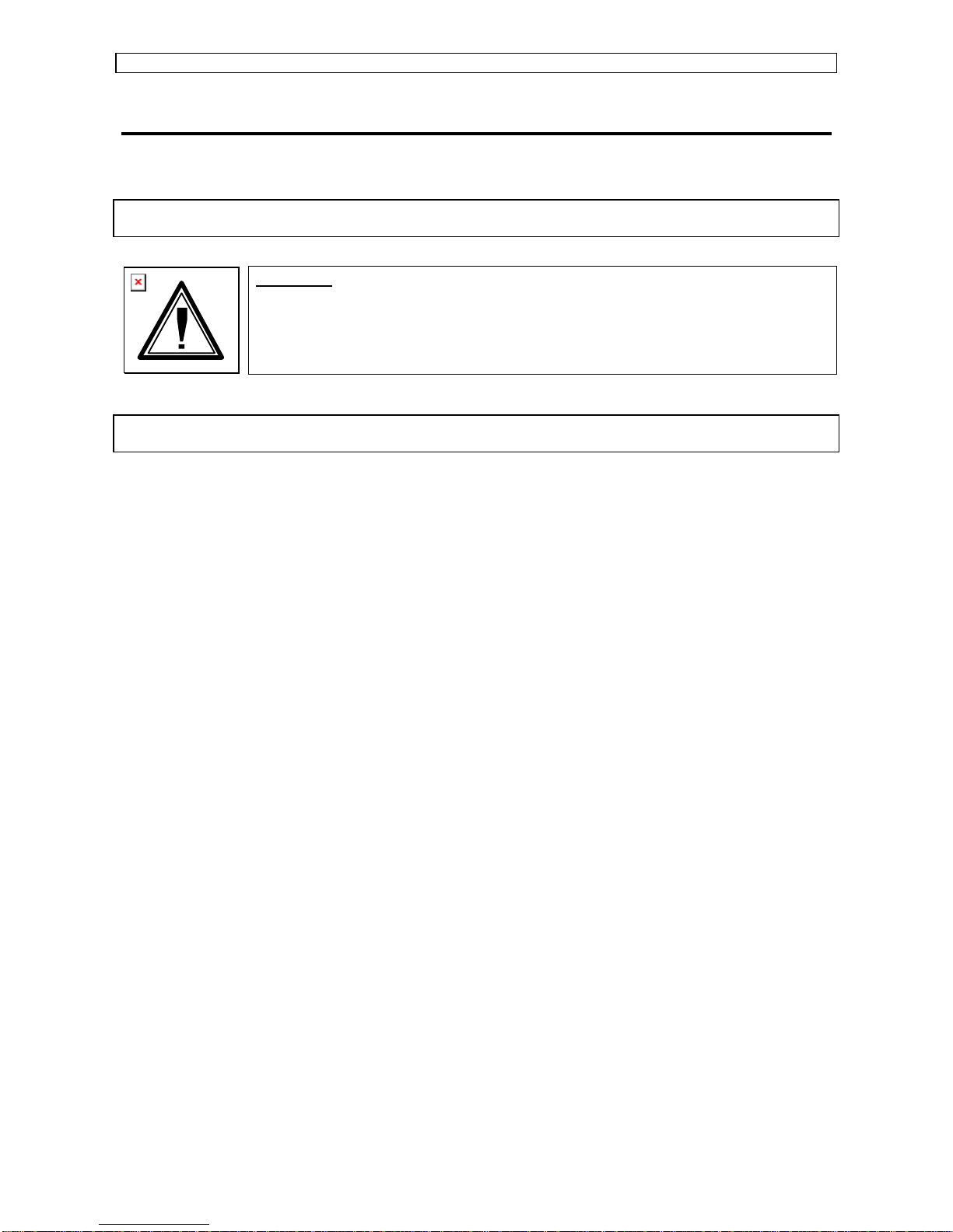
Dear Customer,
Mutoh’s new Rockhopper high-resolution drop-on-demand piezo electric outdoor inkjet
printer series consists of two models, i.e. a 62” (157 cm) and a 48” (122 cm) version.
Maximum print widths offered are 116 cm for the Rockhopper48 and 155 cm for the
Rockhopper62.
Application possibilities encompass outdoor poster printing, banners, long-term backlit
signage, building and construction announcements, vehicle graphics, durable indoor
graphics, POS displays, …
The printers use a newly developed eco-solvent ink. Inks are offered in six colours, i.e.
cyan, magenta, yellow, black, light cyan & light magenta. Prints are UV- and waterresistant for up to three years outdoors(*). Lamination is required for heavy-duty
applications.
The Rockhopper printers offer various print resolutions, from 360 dpi & 720 dpi, up to 1440
x 720 dpi and diagonally interpolated 1440 x 1440 dpi. Print speeds vary between 14.49
m²/h at 360 x 180 dpi, 3.6 m²/h at 720 x 720 dpi and 0.68 m²/h at 1440 x 1440 dpi.
For the Rockhopper, Mutoh will be offering certified media such as banner and vinyl,
optimised for use with the Mutoh Eco-solvent inks. As standard, Mutoh Rockhopper
printers are equipped with an automatic take-up system for unattended printing and
separately controllable pre and post heaters for instant drying and a wider media
compatibility.
(*) Accelerated weather tests predict up to 3 years outdoor durability. Outdoor durability is
location and application dependant.
Page 6

Operation Instructions Rockhopper Printer
AP-75024 Rev. 1.2. – 18/08/2002
Page 7

Operation Instructions Rockhopper Printer
AP-75024 Rev. 1.2. – 18/08/2002
TABLE OF CONTENTS
ROCKHOPPER ECO-SOLVENT PRINTER OPERATION
INSTRUCTIONS...............................................................................1
Regulatory and Safety Information.......................................................... 9
EMC Statement for CE Marking ...................................................................................9
FCC Compliance ..........................................................................................................9
Safety Labels Safety Labels, Symboles de sécurité, Sicherheitssymbole..................10
Installation Procedures ........................................................................... 17
Installation requirements: Selecting an adequate place for setting up your Equipment
...................................................................................................................................17
Unpacking your Rockhopper printer ...........................................................................19
What’s in the Box?......................................................................................................20
Getting to know the Printer parts and components.....................................................21
Assembling the printer................................................................................................23
The Parallel interface..................................................................................................29
Tips to use high-speed ECP parallel communication .................................................30
Installation of network interface board........................................................................31
Connecting the power cable / disconnect device........................................................33
Preparing for a job................................................................................... 35
Installing the ink cassettes..........................................................................................35
Adjusting Head Height................................................................................................42
Loading media............................................................................................................43
Using Pre- and post-heaters.......................................................................................55
Using Eco-Solvent Ink ................................................................................................55
Using Pigmented Ink................................................................................................... 55
Print Origin Control.....................................................................................................56
Micro-banding elimination...........................................................................................58
Daily Maintenance.................................................................................... 61
Replacing the ink cassettes........................................................................................61
Switching between dye inks and pigmented inks or changing to Eco-Solvent Ink......62
Cleaning the head cleaning wiper...............................................................................65
Replacing the cutting blade ........................................................................................66
Periodical Maintenance ..............................................................................................68
Understanding the control panel & printer controls............................. 69
Guided tour around the control panel .........................................................................69
Heater System Control Panel.....................................................................................74
Menu mode operation.................................................................................................75
Print modes accessible via the control panel..............................................................77
Page 8

Operation Instructions Rockhopper Printer
AP-75024 Rev. 1.2. – 18/08/2002
Page 9
Regulary & Safety Information Operation Instructions Rockhopper Printer
Page
9
AP-75024 Rev. 1.2. – 18/08/2002
REGULATORY AND SAFETY INFORMATION
EMC STATEMENT FOR CE MARKING
Warning:
• This is a class A product. In a domestic environment this product may
cause radio interference in which case you may be required to take
adequate measures.
FCC COMPLIANCE
This equipment complies with the requirements for a Class A computing device in the FCC
rules, part 15, subpart J.
Operation of this device in a residential area may interfere with television reception or
operation of utilities.
Printers generate weak radio signals and may interfere with television reception and
utilities. If the printer does interfere with radio or TV reception, try the following :
• Change the direction of your radio and TV reception antenna or feeder.
• Change the direction of the printer.
• Move either the printer or the receiving antenna so there is more distance between
them.
• Be sure the printer and the receiving antenna are on separate power lines.
Page 10

Regulary & Safety Information Operation Instructions Rockhopper Printer
Page
10
AP-75024 Rev. 1.2. – 18/08/2002
SAFETY LABELS
SAFETY LABELS, SYMBOLES DE SÉCURITÉ,
SICHERHEITSSYMBOLE
Safety Labels are attached to the internal and external area of the printer to alert you to
potentially hazardous situations or conditions. The following safety labels are used in and
on the printer:
La partie externe et interne de l’imprimante porte des symboles de sécurité destinés à
attirer votre attention sur des sources potentielles de danger ou des conditions pouvant
être dangereuses. Les symboles de sécurité suivants sont utilisés à l’intérieur et à
l’extérieur de l’imprimante:
Auf der Innen- und Außenseite des Druckers sind Sicherheitssymbole angebracht, die Sie
auf potentielle Gefahrenquellen oder potentiell gefährliche Bedingungen hinweisen sollen.
Im und auf dem Drucker werden die nachfolgend aufgeführten Sicherheitssymbole
verwendet:
WARNING
♦ Keep fingers clear of opening except when loading media.
This may result in unexpected injury and/or poor image quality.
♦ Ne mettez pas le doigts dans l’ouverture sauf lors du montage du papier. Ceci
peut éventuellement provoquer des blessures ou avoir un effet néfaste sur
l’impression.
♦ Nicht die Finger in die Öffnung stecken, außer wenn Druckmaterial eingesetzt
werden muß.
Das könnte Verletzungen verursachen und den Druckvorgang beeinträchtigen.
THE OPENING / OUVERTURE / ÖFFNUNG
ª
CAUTION
♦ When the message “Clean the wiper” is appeared on the LCD of the
operation panel, clean up the Head Cleaning Wiper. Refer to the User
Guide in detail.
♦ Periodical cleaning can avoid bad print result.
♦ Lorsque le message “Nettoyer le balai” apparaît sur l’ecran LCD du
panneau de commande, nettoyer le balai de nettoyage de la tête.
Reportez-vous au guide de l’utilisateur pour les détails.
♦ Le nettoyage périodique peut éviter la dégradation de la qualité de
l’impression.
♦ Wenn die Meldung “Wischer reinigen” auf dem LCD an der Frontplatte
erscheint, den Kopfwisser reinigen. Nähere Einzelheiten siehe
Bedienungsanleitung.
♦ Periodische Reinigung kann schlechte Druckqualität verhindern.
Page 11
Regulary & Safety Information Operation Instructions Rockhopper Printer
Page
11
AP-75024 Rev. 1.2. – 18/08/2002
CAUTION
♦ The corner edge of the Cutter Guide is sharp. Be careful not to cut your
fingers.
♦ The edge of the cutting tool such as knife is very sharp. When cutting
roll media with knife manually, handle it with care.
♦ Le bord d’angle du guide du cutter est tranchant. Veillez à ne pas vous
couper les doigts.
♦ Le bord des outils de coupe comme un couteau est très tranchant.
Manipulez ces outils avec précaution si vous coupez le rouleau de
papier manuellement au couteau.
♦ Die Eckkante der Schneidevorrichtungsführung ist scharf. Es besteht
Verletzunsgefahr.
♦ Scheidwerkzeuge wie Messer sind sehr scharf. Beim Schneiden von
Rollenmaterial von Hand mit einem Messer vorsichtig vorgehen.
CAUTION
♦ Do not open the front cover or touch the media during printing. This will result in poor
image quality.
♦ If no printing is to be done for some time, remove the media and set the hold lever in the
up position. Otherwise the media may lift up or become wrinckled and you will not be able
to obtain good printing results.
♦ Ne pas ouvrir le couvercle avant pendant l’impression. Et ne touchez pas le papier pendant
l’impression pour éviter que la qualité d’impression ne se dégrade.
♦ Si vous ne comptez pas imprimer pendant un certain temps, retirez le papier et mettez le
levier en position levée. Sinon, le support risque de se soulever et de se froisser et vous ne
pourrez pas obtenir une bonne qualité d’impression.
♦ Wahrend des Druckens nicht die Frontabdeckung öffnen und nicht das Druckmaterial
berühren. Das kann das Druckergebnis beeinträchtigen.
♦ Wenn längere Zeit nicht gedruckt werden soll, das Druckmaterial herausnehmen und die
Haltehebel in die obere Position stellen. Anderenfalls kann sich das Druckmaterial heb en
oder falten, so daß keine guten Druckergebnisse mehr zu erzielen sind.
CAUTION
If the media feed is not operating properly the media will jam and you will not be able to obtain good pri nting results.
♦ Don't use media that is curled, creased or torn.
♦ The media must be mounted correctly
♦ Media should be acclimatized to the environment for about 30 minutes before it is used.
♦ When roll media is mounted, the selector on the front panel must be set to roll media. If cut media is selected
when roll media is mounted, about 3m of media will be fed.
Si l'alimentation de papier ne fonctionne pas normalement, des bourrages risquent de se produire et vous ne
pourrez pas obtenir une bonne qualité d'impression.
♦ Ne pas utiliser de papier recourbé, plissé ou déchiré.
♦ Le papier doit être chargé correctement.
♦ Le papier devra être acclimaté à l'environnement pendant environ 30 minutes avant d'être utilisé.
♦ Lorsque le rouleau de papier est chargé, le sélecteur du panneau frontal doit être réglé sur "Papier en rouleau".
Si, "Papier coupé" est sélectionné alors qu'un rouleau de papier est chargé, 3m de papier environ seront
alimentés.
Wenn das Druckmaterial nicht einwandfrei transportiert wird, staut es sich, und es können keine guten
Druckergebnisse erzielt werden.
♦ Keine gerolltes,geknittertes oder eingerissenes Druckmaterial verwenden.
♦ Das Druckmaterial muß korrekt eingesetzt werden.
♦ Das Druckmaterial sollte vor Gebrauch etwa zehn Minuten lang der Betriebsumgebung angepaßt werden.
♦ Beim Einsetzen von Rollenmaterial muß der Wahlschalter an der Frontplatte auf Rollenmaterial eingestelt
werden. Steht der Wahlschalter auf Einzelblattmaterial, wenn Rollenmaterial eingesetzt ist, werden etwa 3m
Druckmaterial zugeführt.
Page 12
Regulary & Safety Information Operation Instructions Rockhopper Printer
Page
12
AP-75024 Rev. 1.2. – 18/08/2002
CAUTION
Precautions when the hold lever is up.
♦ Don't put the hold lever up while the head is operating (printing, media size detection,cutting,etc..)
The head and media keeper blade may touch, causing damage and poor image quality.
♦ When the lever is up for media mounting, etc…, make sure the head is in a position where it does not
come into contact with the media keeper blade.
♦ Don't move the head while the lever is up. The media keeper blade must not come into contact with the
head.
Precautions when replacing the cutter.
♦ The power supply must be switched off and the hold lever must be in the down position when the cutter is
being replaced.
Précautions lorsque le levier de maintien est levé.
♦ Ne pas lever le levier de maintien lorsque la tête fonctionne (pendant l'impression, la selection du support
d'impression, la coupe du papier, le nettoyage, etc..). La tête et la lame de maintien du papier peuvent
entrer en contact et provoquer des dommages ou nuire à la qualité de l'image.
♦ Lorsque le levier est levé pour monter le support ou autres, veillez à ce que la tête soit dans une postion où
elle n'entre pas en contact avec la lame de maintien du support.
♦ Ne pas déplacer la tête lorsque le levier est levé. La lame de maintien du support ne doit pas entrer en
contact avec la tête.
Précautions lors du remplacement du cutter.
♦ Mettre l'appareil hors tension et abaisser le levier de maintien pendant le remplacement du cutter.
Vorsichtsmaßnahmen bei hochgestelltem Haltehebel.
♦ Den Haltehebel nicht hochstellen, während der Kopf arbeitet (beim Drucken, bei der Erkennung der
Druckmaterialgröße, beim Schneiden des Druckmaterials, bei der Reinigung, usw..). Der Kopf und das
Druckmaterial-Haltemesser könnten sich dabei berühren und Beschädigungen od er schlechte Bildqualität
verursachen.
♦ Wenn der Hebel zum Einsetzen von Druckmaterial usw. Hochgestellt ist, ist darauf zu achten, daß er sich
nicht in einer Position befindet, in der er in Kontakt mit dem Druckmaterial-Haltemesser kommt.
♦ Den Kopf nicht bewegen, während der Hebel hochgestellt ist. Das Druckmaterial-Haltemesser darf nicht in
Kontakt mit dem Kopf kommen.
Vorsichtsmaßnahmen beim Auswechseln der Schneidevorichtung.
♦ Beim Auswechseln der Schneidevorrichtung muß die Stromversorgung ausgeschaltet sein und der
Haltebhebel muß sich in der unteren Position befinden.
WARNING
♦ The edges of the steel belt are sharp and should not be
touched.
♦ Les bords de la courroie métallique sont tranchants et ne
doivent pas être touchés.
♦ Die Kanten des Stahlriemens sind scharf und sollten nicht
berürht werden.
CAUTION
♦ The pressure roller must be in the up position whenever it is to
be moved.
♦ Le rouleau de pression doit être mis en position levée lorsqu'il
doit être déplacé.
♦ Die Andruckrolle muß sich zum Verschieben in der oberen
Position befinden.
Page 13
Regulary & Safety Information Operation Instructions Rockhopper Printer
Page
13
AP-75024 Rev. 1.2. – 18/08/2002
CAUTION
♦ The cutter blade is a consumable item. When its cutting performance deteriorates
it should be replaced in accordance with the User Manual.
♦ The media sensor section and printing board should be cleaned regurarly as
detailed under daily maintenance in the User Manual.
♦ La lame du cutter est un article consommable qui doit être remplacé
conformément à la procédure indiquée dans le mode d'emploi lors que les
performances de coupe se dégradent.
♦ La section de détection du support et la carte de traçage doivent être nettoyés
périodiquement de la manière indiquée pour l'entretien journalier dans le mode
d'emploi.
♦ Die Schneidevorichtung ist ein Verbrauchsartikel. Wenn ihre Schneideleistung
nachlaßt, muß sie entsprechend den Anweisungen in der Bedienungsanleitung
ausge wechsel t werden.
♦ Der Bereich des Druckmaterialsensors und die Zeichenfläche sollten regelmäßig
gereinigt werden, wie unter tâgliche Wartung in der Bedienungsanleitung
beschrieben.
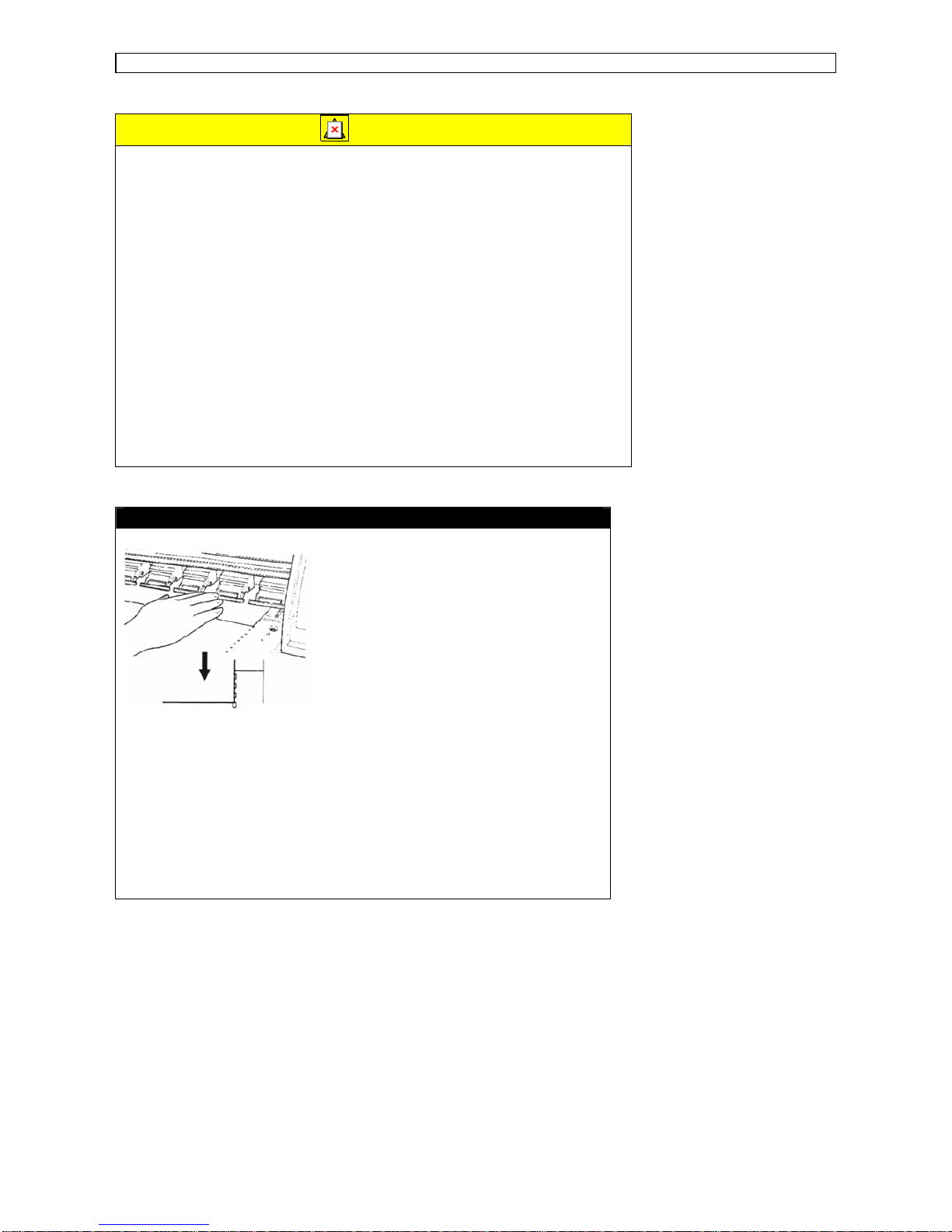
MOUNTING CUT MEDIA
♦ Pass the media between the media keeper
blade and the printing board.
♦ Align the front right corner of the media
with the edge of the paper guide.
♦ Align the right side of the media with the
center of the alignment line (hole).
♦ Passez le papier entre la lame de maintien
et le carte d’impression.
♦ Alignez le coin avant droit du papier avec
le bord du guide de papier.
♦ Alignez l’extrémité droite du papier sur le
centre de la ligne d’alignement (orifice).
♦ Das Druckmaterial zwischen dem
Druckmaterial-Haltemesser und der
Zeichenfläche hindurchführen.
♦ Die vordere rechte Ecke des
Druckmaterials auf die Kante der
Papierführung ausrichten.
♦ Die rechte Seite des Druckmaterials auf
die Mitte der Ausrichtungslinie (Loch)
ausrichten.
Page 14

Regulary & Safety Information Operation Instructions Rockhopper Printer
Page
14
AP-75024 Rev. 1.2. – 18/08/2002
LOADING ROLL MEDIA
1. Remove the tape from the
roll media and pull out a rather
long length of roll media.
1. Retirez la bande du rouleau
et tirez une bonne longueur de
papier.
1. Das Klebeband von der Rolle
abziehlen und ein ziemlich
langes Stück Rollenmaterial
herausziehen.
2. Insert the end of the roll media between the
pressure roller and the drive roller and pull
out a fairly long length of roll media.
2. Introduisez l’extrémité du papier en rouleau
entre le rouleau de pression et le rouleau
d’entraînement et tirez une bonne longueur
de papier.
2. Das Ende des Rollenmaterials zwischen der
Andruckrolle und der Antriebsrolle einsetzen
und ein ziemlich langes Stück Rollenmaterial
herausziehen.
CHECK THE POSITION OF THE ROLL MEDIA
Rotate the scroller by hand, taking several turns of
roll media and check the position of the roll media.
The position is correct if the right side of the roll
media is in the center of the alignment line (hole)
Faites tourner la couronne de la main pour faire
plusieurs tours au rouleau de papier et vérifiez la
position du rouleau. Elle est normale si l’extrémité
de droite du rouleau se trouve à l’extrémité de
droite du rouleau d’entraînement et au centre de la
ligne d’alignement (orifice).
Durch mehrmaliges manuelles Drehen der
Papierspindel Rollenmaterial vor transportieren und
seine Position prüen. Das Rollenmaterial hat die
richtige Position wenn sich seine rechte Seite am
rechten Ende der Antriebsrolle und in der Mitte der
Ausrichtungslinie (Loch) befindet.
Page 15
Regulary & Safety Information Operation Instructions Rockhopper Printer
Page
15
AP-75024 Rev. 1.2. – 18/08/2002
ADJUSTING ROLL MEDIA POSITION
If the position of the roll media is incorrect, adjust the position of the roll
media as shown in the diagram below.
Si la position du rouleau est incorrecte, réglez-la de la manière
indiquée sur le schéma ci-dessous.
Wenn sich das Rollenmaterial nicht in der richtigen Position befindet,
muß es wie in der Abbildung unten gezeigt justiert werden.
If the roll needs to be moved to
the right.
Si le rouleau de papier doit être
retiré vers le côté droit.
Wenn das Rollenmaterial nach
rechts verschoben werden muß.
If the roll needs to be moved to
the left.
Si le rouleau de papier doit être
retiré vers le côté gauche.
Wenn das Rollenmaterial nach
links verschoben werden muß.
CAUTION
♦ Ink cartridges must not be removed during printing or poor image quality will result.
♦ Keep fingers clear of the ink cartridge box. It contains projecting parts which may cause
you an unexpected injury
♦ When removing or inserting the waste fluid box, be careful not to tilt it. You may spill ink
on your clothing and the equipment.
♦ La cartouche d’encre ne doit pas être retirée pendant l’impression, ceci pouvant
affecter sérieusement la qualité de l’impression.
♦ Ne pas mettre les doigts à l’intérieur du carton de la cartouche d’encre. Il contient des
pièces protubérantes qui pourrait vous blesser par inadvertance.
♦ Veillez à ne pas incliner le cartes d’encre usagée lors de son retrait ou de sa mise en
place. Vous risquez de vous salir ou de salir les appareils si vous renversez de l’encre
♦ Die Tintenpatrone darf während des Druckens nicht entfernt werden. Das könnte den
Druckvorgang erheblich beeinträchtigen.
♦ Nicht die Finger in den Tintenpatronenbehälter stecken. Dieser enthält vorstehende
Teile die Verletzungen verursachen können.
♦ Den Alttintenbehälter beim Herausnehmen und Einsetzen nicht neigen. Dabei könten
Alttinte herauslaufen und Kleidung und Gerät beschmutzen.
Page 16

Regulary & Safety Information Operation Instructions Rockhopper Printer
Page
16
AP-75024 Rev. 1.2. – 18/08/2002
Page 17

Installation Procedures Operation Instructions Rockhopper Printer
Page
17
AP-75024 Rev. 1.2. – 18/08/2002
INSTALLATION PROCEDURES
Warning:
Make sure to connect the power cable only after all the steps of the
installation procedure are completed.
INSTALLATION REQUIREMENTS: SELECTING AN ADEQUATE
PLACE FOR SETTING UP YOUR EQUIPMENT
The location where you set up your equipment is very important. Please see to it that it
meets following conditions:
♦ Power supply:
- Voltage: 200 to 240 VAC or 100 to 120 VAC
- Frequency: 50/60 Hz ± 1 Hz
- Current: < 10 A (110 V)
< 5 A (220 V)
♦ Ambient conditions:
• Operating environment
- Temperature: 10°C to 35°C
- Humidity: 20% - 80% non-condensing
• Storage environment
- Temperature: -10°C to 60°C
- Humidity: 20% - 90% non-condensing
• Variation rate
- Temperature: 2°C per hour
- Humidity: 5% per hour
♦ Do not connect the printer to a power supply used by other devices that could interfere
with your printer.
♦ Do not use thinner, benzene or similar agents on the printer.
♦ Only use original Mutoh ink cassettes. Use of different ink cassettes might cause
damage to your printer. When using non Mutoh ink cassettes, the ink supply system,
the heads as well as the cleaning system will be considered out of warranty.
♦ Keep ink cassettes out of the reach of children.
♦ Store your ink cassettes in a cool place. The Rockhopper ink could get frozen,
however, if you store your ink below -18°C. In this case, leave your cassettes at room
temperature for at least three hours before using them.
Page 18

Installation Procedures Operation Instructions Rockhopper Printer
Page
18
AP-75024 Rev. 1.2. – 18/08/2002
♦ Protect your printer from moisture, dust, draughts and direct sunlight.
♦ It is best to keep your machine away from open windows and air-conditioners.
♦ See to it that there is an adequate space around the printer so that ventilation is not
obstructed.
♦ Avoid using your Rockhopper printer near heating systems, such as stoves or heaters.
♦ Avoid using your printer under strong lighting, such as halogen lamps or light bulbs.
♦ When selecting a place for your printer, leave at least 1 m in front and at the sides, and
1 m at the rear.
Page 19
Installation Procedures Operation Instructions Rockhopper Printer
Page
19
AP-75024 Rev. 1.2. – 18/08/2002
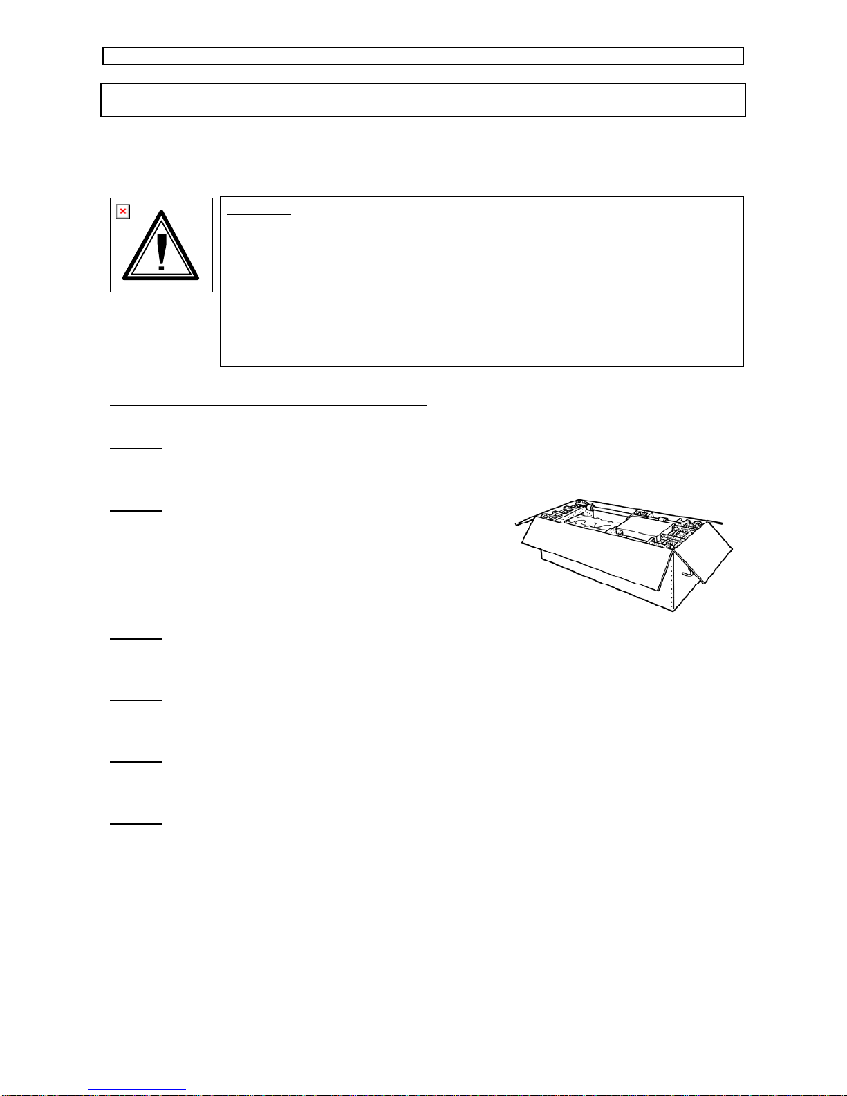
UNPACKING YOUR ROCKHOPPER PRINTER
The printer body and printer Take-up system are packed in two separate boxes. Unpack
the printer body first.
Caution:
• When unpacking the printer, check whether all parts described in the
parts list are included in the box. Consult your dealer if anything
seems to be missing.
• Lifting the machine out of the box should be done by four people.
• Protect the printer from shocks.
• Do not dismantle the unit.
Procedure for unpacking the printer:
Step 1:
Remove the top cover cardboard and big sleeve.
Step 2:
Take out the leg set, accessories box, extra media
scroller, beams,…
Step 3:
Open the printer body box.
Step 4:
Remove all plastic and cardboard pieces holding the printer body.
Step 5:
Take out your media scroller
Step 6:
Check whether all parts described in the parts list are included in the box. Consult your
dealer if anything seems to be missing.
Page 20
Installation Procedures Operation Instructions Rockhopper Printer
Page
20
AP-75024 Rev. 1.2. – 18/08/2002
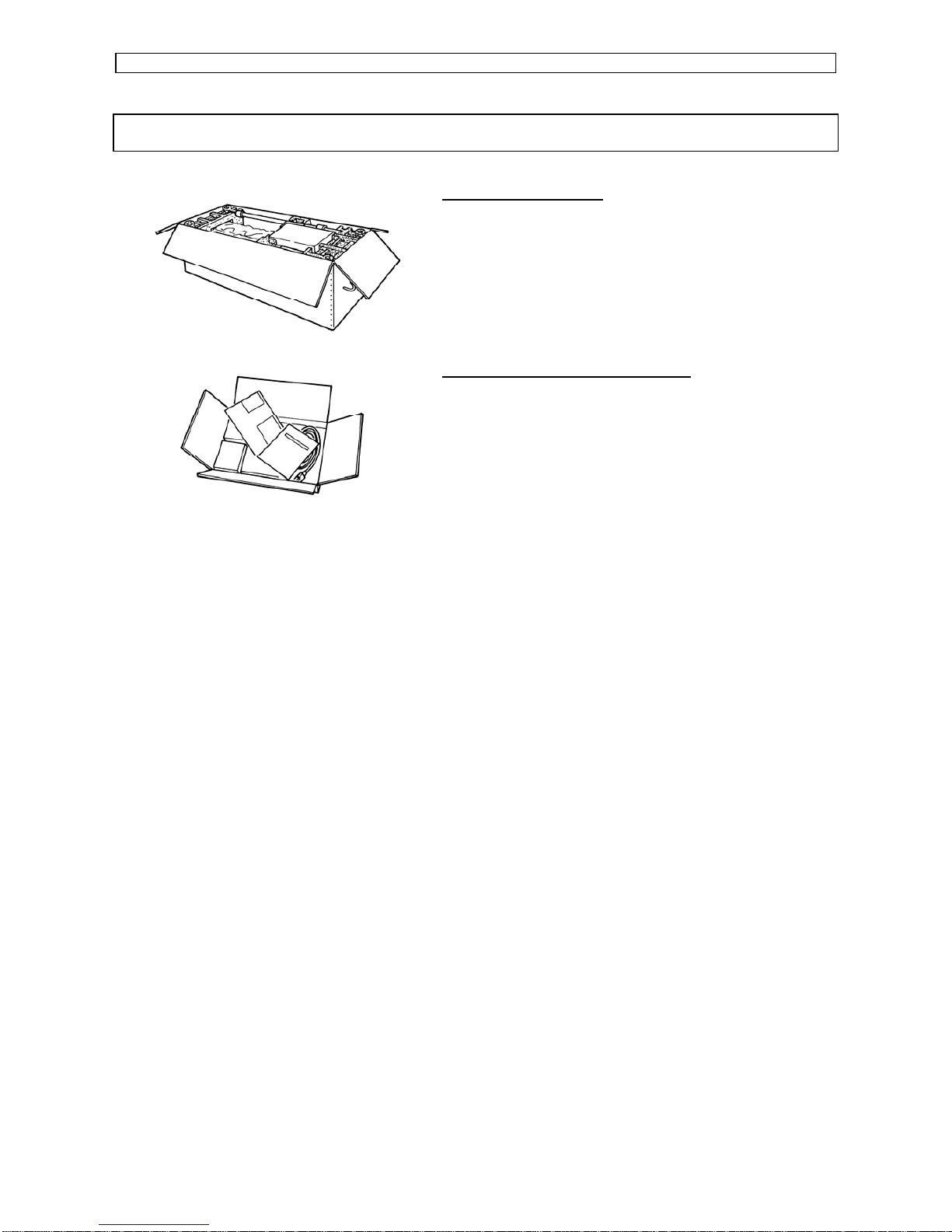
WHAT’S IN THE BOX?
What’s in the box ?
• Rockhopper printer unit
• Printer stand
• 2 media scrollers (2” / 3”) including plastic
flanges
• Scroller Slip Ring
• 1 Sheet-off knife, pre-installed in head
• Onyx PosterShop™ Lite – Mutoh Edition
Accessories kit consisting of:
• Power cable
• User’s Guide
• Extra Box with Roll Take-Up System
Page 21
Installation Procedures Operation Instructions Rockhopper Printer
Page
21
AP-75024 Rev. 1.2. – 18/08/2002
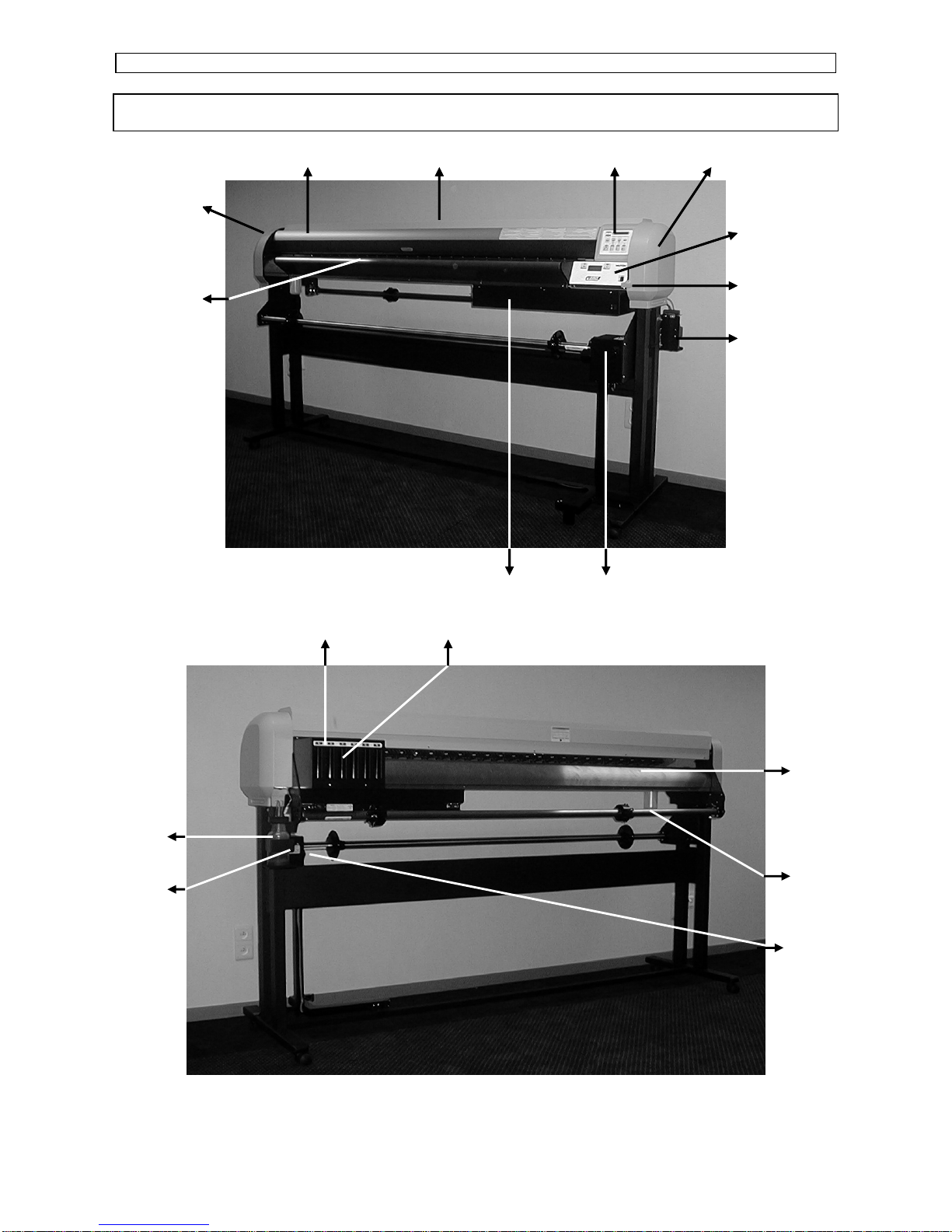
GETTING TO KNOW THE PRINTER PARTS AND COMPONENTS
Left Cover
Front Paper
Guide
Front Cover Y-rail Cover Operating Panel Right Cover
Heater Panel
Pressure Lever
Waste Bottle
Control Box Take-up System
Left Cover
Front Paper
Guide
Front Cover Y-rail Cover Operating Panel Right Cover
Heater Panel
Pressure Lever
Waste Bottle
Control Box Take-up System
Cartridge Cover 6 Ink Slots
Rear Paper
Guide
Scroller
Waste
Bottle
Scroller
Adjusting
Screw
Scroller Slip
Ring
Page 22
Installation Procedures Operation Instructions Rockhopper Printer
Page
22
AP-75024 Rev. 1.2. – 18/08/2002
Part Description
Covers
The protective covers protect the action environment.
Opening a cover immediately pauses printing which resumes
when the cover is closed.
Operation Panel
Positive Touch keyboard with integrated LCD-Display.
Heater Panel
To control the pre- and post heaters with integrated LCDDisplay.
Pressure Lever
Lowers / Releases pressure rolls to load / unload media.
Take-up system
Used when using roll media.
Control box
Box with the main electrical components..
Front Paper Guide
The print plate is a firm, flat base which supports the media
during printing and houses the vacuum system and postheaters.
Rear Paper Guide
Support the media during printing and houses the preheaters.
Scroller
Feeds through the roll media core to hold the media.
Scroller adjusting
screw
To adjust the position of the roll media.
Scroller Slip Ring
Prevents unwinding of roll media.
Ink cassette slots
Hold / detect the ink cassettes which are in use.
Waste bottle
Collects inkflow resulting from: purging, cleaning.
Caution:
• Do not use the printer as a shelf to store equipment.
• Do not lean on Front Paper Guide, Cartridges, … This may result in
unrecoverable damage of your machine.
Page 23
Installation Procedures Operation Instructions Rockhopper Printer
Page
23
AP-75024 Rev. 1.2. – 18/08/2002
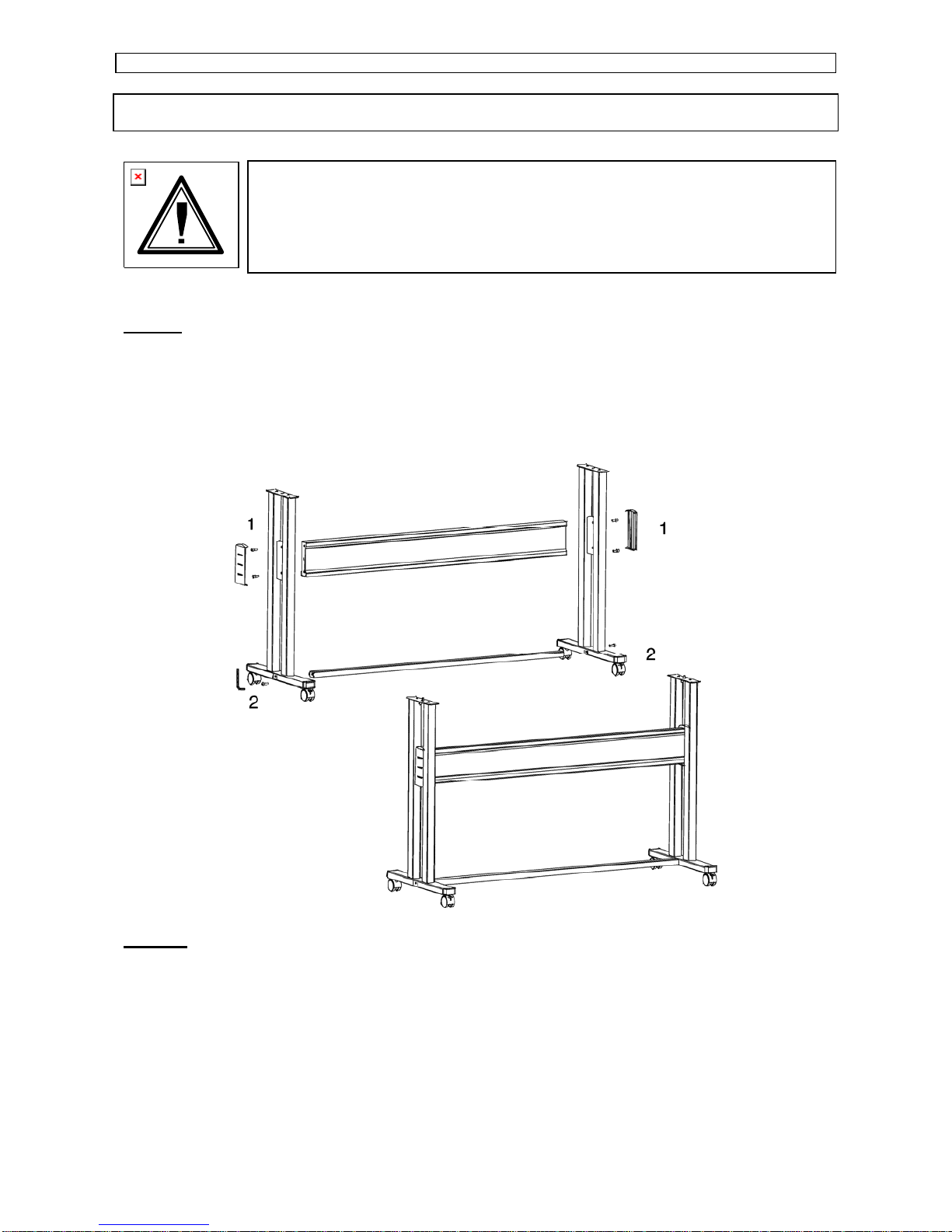
ASSEMBLING THE PRINTER
Caution:
• Before lifting the printer body out of the box, make sure to remove all
plastic wrapping materials first, in order to avoid that the machine slips
from your hands.
Step 1:
Unpack the stand and assemble it by screwing the left and right stand legs to the cross
beam (upper bar)(1) and to the cross bar (lower bar)(2). To do this, use the 4 long
hexagon bolts and the large hex wrench provided to secure the cross beam (1), and 2 long
hexagon bolts to secure the cross bar (2). Make sure the caster wheels are on the front.
After securing the bolts permanently, put on the two plastic side covers.
Step 2 :
First make sure to mount the left end plate (plate without motor box) to the left leg of the
stand.
Page 24
Installation Procedures Operation Instructions Rockhopper Printer
Page
24
AP-75024 Rev. 1.2. – 18/08/2002
Hook the left end plate between the leg assembly. Turn the left end plate diagonally, so
that you can put it in-between the left leg and then turn it right to fix it into place by means
of the hooks.
Fasten the left end plate temporarily with 2 bolts + washers (use a 3 mm hex key) onto the
bracket.
Push the endplate as much as possible to the upper side of the leg assembly, so you can
easily screw the printer body onto the stand.
Page 25

Installation Procedures Operation Instructions Rockhopper Printer
Page
25
AP-75024 Rev. 1.2. – 18/08/2002
Step 3 :
Hook the right end plate between the leg assembly. To do so, follow the same procedure
as for the left end plate.
Hook the right end plate between the leg assembly. Turn the right end plate diagonally, so
that you can put it in-between the right leg and then turn it right to fix it into place by means
of the hooks.
Fasten the right end plate temporarily with 2 bolts + washers (use a 3 mm hex key) onto
the bracket.
Push the endplate as much as possible to the upper side of the leg assembly, so you can
easily screw the printer body onto the stand.
Page 26

Installation Procedures Operation Instructions Rockhopper Printer
Page
26
AP-75024 Rev. 1.2. – 18/08/2002
Step 4:
Caution:
• For safety, at least four people are needed for assembling the printer.
• When taking the main unit out of the carton, remove the vinyl first and
handle the printer directly. There is a risk of your hands slipping if the
main unit is handled with the vinyl on.
• The main unit must be lifted by four people at the places marked (1) to
(8) below. If it is lifted at other places (left and right side covers, ink
cartridge cover, etc.) the printer may fall and cause injury or damage.
Fix the printer body onto the leg assembly using the two wing
screws. As mentioned in step 2 & 3 the end plates should be pulled
as much as possible towards the upper part of the stand. To do so,
loosen a little bit the bolts temporarily fixing the endplates with a hex
key of 3 mm and make sure that they are pulled as much as
possible towards the stand. Now you can fix both wing screws
firmly. Once the wing screws are fastened, you can secure the
bolts on the endplates (see step 2 & 3) firmly with the hex key.
Page 27

Installation Procedures Operation Instructions Rockhopper Printer
Page
27
AP-75024 Rev. 1.2. – 18/08/2002
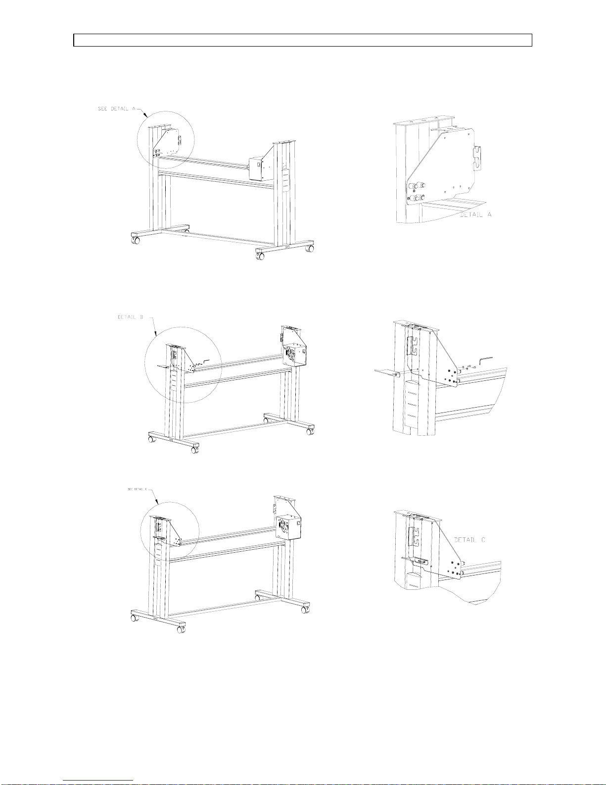
Step 5 :
The sensor assembly should be mounted on the right side of the stand. Take the sensor
bracket and put it through the outer slothole of the sensor assy.
Now you can fix the sensor assy.
Fix the sensor assembly smoothly to the motor box, using 2 bolt + washers (use upper
holes) (detail A).
Hook the sensor bracket over the leg and secure it with a bolt + washer (detail B).
Page 28

Installation Procedures Operation Instructions Rockhopper Printer
Page
28
AP-75024 Rev. 1.2. – 18/08/2002
Step 6:
Loosen the wing screw which is fixed to the printing table (4) and remove the metal fixing
plate (5), which blocks the printer head during transportation. (See 4 & 5 on figure below).
Keep the metal fixing plate and wing screw, since the printing head needs to be
blocked during any transportation of your printer.
Caution:
• Take care not to drop the wing screw inside the printer body. Should
it fall in, do not boot up your printer until the wing screw has been
safely removed.
Remove the tape that locks the sheet-off mechanism during transportation
(See 6 on figure below).
Step 7:
Remove the cable block(s) between rail and cover (7).
Remove the lever block (8).
Step 8 :
Install the Waste Bottle (2 screws). Do not forget to connect the connector and the waste
tubes.
Step 9:
After setting up the printer, wheel it to the
desired location and lock the caster wheels.
Page 29

Installation Procedures Operation Instructions Rockhopper Printer
Page
29
AP-75024 Rev. 1.2. – 18/08/2002
THE PARALLEL INTERFACE
Caution:
• When connecting the printer to your computer, make sure that both
your printer and your computer are switched OFF.
Note:
• For optimum output, please use a cable recommended by Mutoh.
The printer can use the Centronics interface (IEEE1284 compatible, Nibble, ECP).
Connect to the printer as shown in the following diagram with an interface cable (option)
for the connection system you will use. Connect to the host computer with another
interface cable.
Note:
• The use of an unnecessary long cable may influence your data
transmission. Therefore, keep your interface cable as short as
possible.
• An Ethernet board RJ-ETH14TX (for networking) is available as an
optional extra.
Page 30

Installation Procedures Operation Instructions Rockhopper Printer
Page
30
AP-75024 Rev. 1.2. – 18/08/2002
TIPS TO USE HIGH-SPEED ECP PARALLEL COMMUNICATION
• If the parallel port setting on the printer is set to BI CENTRO (See Menu Mode
Operation – Menu Structure Overview) your printer is ready for high-speed bidirectional communication.
• In order to be able to use this high-speed mode without problems please note:
• Computer Bios for parallel port should be set to ECP
• Only use a shielded and balanced parallel cable, which is IEEE 1284 compliant.
• If your RIP software is protected with a hardware lock (dongle), which needs to be
placed on the parallel port, it is best to have available 2 parallel ports.
– One port to connect: hardware lock, scanner, external drive or CD-ROM,…
– One port (ECP) directly connected to the printer.
In case either of the above mentioned topics is not respected you may encounter all kinds
of printer artifacts such as: unexplainable error messages, sheet-off during printing,
unexpected media feed during printing, etc…
If this occurs, switch your system to unidirectional parallel communication.
– Set print parallel port to Mode > CENT RO
– Set computer parallel port Bios to SPP or EPP
The data transfer will then slow down and the artifacts will disappear. Before switching
back to the high-speed bi-directional parallel mode, have your computer system examined
closely by a trained computer technician.
Page 31

Installation Procedures Operation Instructions Rockhopper Printer
Page
31
AP-75024 Rev. 1.2. – 18/08/2002
INSTALLATION OF NETWORK INTERFACE BOARD
The standard interface for the Rockhopper printer has a parallel Centronics compatible
interface as standard equipment. The network interface board, RJ-ETH14TX, for
connection to EtherNet is also available as an option.
The following procedure explains how to install the network interface board.
Caution:
• When installing the Network interface board, make sure that the
Rockhopper printer is switched off and the power cable is
disconnected.
To install the network card proceed as follows:
Step 1 :
Loosen the two screws, which are fixed to
the interface cover plate on the left side of
the Board box below the printer and remove
the plate.
1. Interface cover plate
2. Board box
Step 2 :
Insert the optional interface board into the
slot as shown in the diagram. When the
interface board has reached the back, push
it again to ensure it is pushed fully back.
1. Interface board
Caution:
• Electronic components are susceptible to damage by static
electricity. Remove static charge from your clothes and body by
touching your hands to the board box before you touch the network
interface board.
Step 3 :
Fasten the two interface mounting screws.
Page 32

Installation Procedures Operation Instructions Rockhopper Printer
Page
32
AP-75024 Rev. 1.2. – 18/08/2002
Step 4 :
Connect a Category 5 EtherNet cable compatible with both 10BASE-T and 100BASE-TX
to the connector on the interface board. Connect the other end of the Ethernet cable to
the 10BASE-T or 100BASE-TX network hub.
10BASE-T/100BASE-TX Compatible
Ethernet Cable (Category 5)
Page 33

Installation Procedures Operation Instructions Rockhopper Printer
Page
33
AP-75024 Rev. 1.2. – 18/08/2002
CONNECTING THE POWER CABLE / DISCONNECT DEVICE
1) Make sure the printer’s power switch is turned OFF.
2) Make sure the power of the Heating System and the Roll Take-Up System are turned
OFF.
3) Plug the printer-end of the power cable into the connector at the back of the printer.
4) Connect the cable of the Roll-Take-Up System with the Printer body.
5) Plug the other end of the power cable into an electrical outlet of the correct voltage and
with a proper grounding.
• Power supply:
- Voltage: 200 to 240 VAC or 100 to 120 VAC
- Frequency: 50/60 Hz ± 1 Hz
- Current: < 10 A (110 V)
< 5 A (220 V)
Note:
• When you turn off the power, please note that your printer needs a
few seconds to perform its shut down sequence.
• To this end, wait for at least five seconds to switch the printer on
again.
• The disconnect device is the plug on the power supply cord.
Page 34

Installation Procedures Operation Instructions Rockhopper Printer
Page
34
AP-75024 Rev. 1.2. – 18/08/2002
Page 35

Preparing for a job Operation Instructions Rockhopper Printer
Page
35
AP-75024 Rev. 1.2. – 18/08/2002
PREPARING FOR A JOB
INSTALLING THE INK CASSETTES
PRECAUTIONS WHEN USING INK CASSETTES :
Please read below recommendations carefully before you start using your Rockhopper ink
cassettes.
Caution:
• It is recommended to avoid any direct contact with the inks. If you
come in close contact with the inks, please pay attention to the
following first-aid measures:
Eye contact: Rinse out the ink with a large quantity of water and
consult your doctor.
Skin contact: Wash off the ink with soap and water.
Ingestion: Rinse your mouth immediately, drink a large quantity of
water or milk and consult your doctor.
• Keep the ink cassettes out of the reach of children.
• The ink cassettes are inflammable (ignition point 63°C). Avoid contact
with heating sources and any sort of ignition source.
Important:
• If you use your Rockhopper printer for the first time, you need to
install 6 cassettes in the slot, which is located at the back of the
printer.
• Before using Eco-Solvent ink, perform a head wash. Tubes, heads
and filters must be clean. Use the special Eco-solvent Transition
Liquid.
• Once you have worked with eco-solvent inks, it is forbidden to change
to another ink type.
• Do not use other ink cassettes but the exclusive Mutoh Rockhopper
ink cassettes. When using non Mutoh ink cassettes, the ink supply
system, the heads as well as the cleaning system will be considered
out of warranty if damage occurs. Also see to it that you install your
cassettes in the correct way. Use of incorrectly coded cassettes may
cause printer damage.
Page 36

Preparing for a job Operation Instructions Rockhopper Printer
Page
36
AP-75024 Rev. 1.2. – 18/08/2002
Notes:
• Unpack the ink cassettes just before installing them in the slot. If you
leave your cassettes open for a long time, they may cause blurred
plots.
• After installing the ink cassettes, do not take them out until you
replace them.
• The ink cassettes have to be used within two years from the date
printed on the cassette. Ink cassettes, which are installed in the
printer, should be used up in six months.
• Moving ink cassettes from a cold place to a warm place may cause
condensation. Always leave the cassettes at room temperature for
more than three hours before using them.
• If the head is stopped during a print cycle, it may leak. To this end,
never turn the power off nor unplug the power cable during printing or
while the printing head moves.
• In case of a power failure during printing, switch off the printer and
manually move the head to the right until you feel that it drops into the
capping position.
• In case a power failure occurs when you are absent, the printer will
move the head to the capping position when power is restored and a
cleaning cycle will take place automatically.
INSTALLING THE INK CASSETTES IN A MUTOH ROCKHOPPER :
Important:
• Before using Eco-Solvent ink, perform a head wash. Tubes, heads
and filters must be clean. Use the special Eco-solvent Transition
Liquid.
• Once you have worked with eco-solvent inks, it is forbidden to change
to another ink type.
A. Going to use Eco-Solvent ink.
If you are going to use Eco-Solvent ink, please perform a head wash. Use the special
Eco-Solvent Transition Liquid.
If you are not going to use Eco-Solvent ink, but Dye or Pigmented Ink, go to point “B.
Installing Ink Cassettes”.
Step 1:
The power switch is located at the right side of the printer,
below the printer body.
Turn the switch ON and put the hold lever in the DOWN
position.
Page 37

Preparing for a job Operation Instructions Rockhopper Printer
Page
37
AP-75024 Rev. 1.2. – 18/08/2002
Step 2:
The printer starts up its initialization routine and the printer display shows the following
message:
Y: Yellow
M: Magenta
C: Cyan
K: Black
O: Orange or Light Cyan
G: Green or Light Magenta
Note :
• If the cover is open or the hold lever is up, the initialization routine will
not start.
Step 3 : Slide the 6 Eco-Solvent Transition Liquid cleaning cassettes into their cartridge
position. (Automatic detection of cleaning cassettes occurs due to label
recognition)
Step 4 : Check if the Waste Bottle if empty. Confirm replacement of the waste box.
Step 5 : Following message will appear :
Press the [VALUE/+] or [VALUE/-] key to select “Yes” and press ENTER.
Step 6 : The cleaning period is approximately 10 minutes.
Step 7 : Remove the cleaning cassettes after ending the cleaning cycle.
Wash Black & Colour?
[Y M C K O G] No cartridge
Page 38

Preparing for a job Operation Instructions Rockhopper Printer
Page
38
AP-75024 Rev. 1.2. – 18/08/2002
Step 8:
Insert 6 ink Eco-Solvent cassettes one by one, respecting the order shown in the
illustration below.
• Ink cassette slots 1 to 4 respectively destined for Black, Cyan,
Magenta and Yellow are coded so that the ink cassettes cannot be
malpositioned.
• Slots 5 and 6 however are NOT CODED. Please check carefully not
to put the ink cassettes into an incorrect slot.
All RIP software drivers developed according to Mutoh guidelines
require:
Slot 5 to contain: Light Cyan or Orange
Slot 6 (leftmost slot) to contain: Light Magenta or Green
• Only in very special applications it might be needed to introduce the
cassettes using another order. In this case carefully follow the
instructions given in the application software user guide.
Step 9:
After having installed the ink cassettes, the printer will display the following message:
Step 10:
After this message, automatic ink replenishment begins.
The “ink refill” message means that ink is being filled into the ink supply system (tubing +
head). The printer is now ready to print.
Caution:
• During ink replenishment, never cut off the electricity. This may cause
damage to your printer.
• In case of a power failure during ink replenishment, proceed as
follows:
1. Switch off the unit (Power Switch) and check to restore the power.
2. Switch on the unit and check that it gives no error messages in the
display.
3. Perform a cleaning cycle and check the test plots.
4. Repeat step 3 until plot quality is acceptable.
User no media
Ink Refill rest 1 M
Page 39

Preparing for a job Operation Instructions Rockhopper Printer
Page
39
AP-75024 Rev. 1.2. – 18/08/2002
Note:
• In case the ink cassettes are installed and the display message “NO
CARTRIDGE” still appears, this means that the ink cassettes are not
inserted correctly. Pull out the cassette(s) indicated and try to insert it
(them) correctly.
• In case of failure of initial ink replenishment, apply head cleaning a
couple of times. If the ink replenish does not commence after several
head cleaning cycles, contact your dealer.
• If the display shows “not original ink” please contact your ink supplier
and make sure to get original Mutoh Rockhopper ink.
B. Installing Ink Cassettes.
Step 1:
The power switch is located at the right side of the printer,
below the printer body.
Turn the switch ON and put the hold lever in the DOWN
position.
Step 2:
The printer starts up its initialization routine and the printer display shows the following
message:
Y: Yellow
M: Magenta
C: Cyan
K: Black
O: Orange or Light Cyan
G: Green or Light Magenta
Note :
• If the cover is open or the hold lever is up, the initialization routine will
not start.
Step 3:
Insert 6 ink cassettes one by one, respecting the order shown in the illustration below.
[Y M C K O G] No cartridge
Page 40

Preparing for a job Operation Instructions Rockhopper Printer
Page
40
AP-75024 Rev. 1.2. – 18/08/2002
• Ink cassette slots 1 to 4 respectively destined for Black, Cyan,
Magenta and Yellow are coded so that the ink cassettes cannot be
malpositioned.
• Slots 5 and 6 however are NOT CODED. Please check carefully not
to put the ink cassettes into an incorrect slot.
All RIP software drivers developed according to Mutoh guidelines
require:
Slot 5 to contain: Light Cyan or Orange
Slot 6 (leftmost slot) to contain: Light Magenta or Green
• Only in very special applications it might be needed to introduce the
cassettes using another order. In this case carefully follow the
instructions given in the application software user guide.
Step 4:
After having installed the ink cassettes, the printer will display the following message:
Step 5:
After this message, automatic ink replenishment begins.
The “ink refill” message means that ink is being filled into the ink supply system (tubing +
head). The printer is now ready to print.
Caution:
• During ink replenishment, never cut off the electricity. This may cause
damage to your printer.
• In case of a power failure during ink replenishment, proceed as
follows:
1. Switch off the unit (Power Switch) and check to restore the power.
2. Switch on the unit and check that it gives no error messages in the
display.
3. Perform a cleaning cycle and check the test plots.
4. Repeat step 3 until plot quality is acceptable.
User no media
Ink Refill rest 1 M
Page 41

Preparing for a job Operation Instructions Rockhopper Printer
Page
41
AP-75024 Rev. 1.2. – 18/08/2002
Note:
• In case the ink cassettes are installed and the display message “NO
CARTRIDGE” still appears, this means that the ink cassettes are not
inserted correctly. Pull out the cassette(s) indicated and try to insert it
(them) correctly.
• In case of failure of initial ink replenishment, apply head cleaning a
couple of times. If the ink replenish does not commence after several
head cleaning cycles, contact your dealer.
• If the display shows “not original ink” please contact your ink supplier
and make sure to get original Mutoh Rockhopper ink.
Page 42

Preparing for a job Operation Instructions Rockhopper Printer
Page
42
AP-75024 Rev. 1.2. – 18/08/2002
ADJUSTING HEAD HEIGHT.
Depending on the media type and media thickness used, it is possible to adjust the
printer’s printhead height accordingly 1.5 mm to 2.0 mm (± 0.15 mm).
The head height can be adjusted using the lever on the left side of the head (please refer
to the picture mentioned above).
When the lever is put in horizontal position (turn counter clockwise) the head is in his
highest position : 2.0 mm
When the lever is turned clockwise, the head is in his lowest position : 1.5 mm.
The lever can only be put in two positions, there are no intermediates.
Typical use :
LOW HIGH
Photo quality output on photo paper type
media
(Mutoh Photo Great Piezo Media, Paper,
Vinyl, Synthetic paper,…)
Thick media or media with fibres (Fabrics)
which may touch the printhead during
printing.
(Canvas, Art Paper, Cardboard,…)
Page 43

Preparing for a job Operation Instructions Rockhopper Printer
Page
43
AP-75024 Rev. 1.2. – 18/08/2002
LOADING MEDIA
1. GENERAL RECOMMENDATIONS WITH REGARD TO PRINTER MEDIA
Important:
• Do not use media that is creased, blemished, torn or curled.
• Problems caused by using media other than that specified by Mutoh
will not be covered by warranty. Always use cut media or roll media
specified by Mutoh.
• Temperature and humidity suitable for printing are shown below. We
recommend setting up in an environment that can be air conditioned
in order to maintain constant temperature and humidity.
Temperature 10°C to 35°C (16°C to 25°C for assured printing
accuracy)
Variation rate: Not more than 2°C per hour.
Humidity 35% to 80% (50% to 60% for assured printing
accuracy) with no condensation.
Variation rate: Not more than 5% per hour.
• The absolute dimensions of printing media will be changed by
variations in temperature and humidity. Therefore, printing media
such as tracing media and high quality media that are readily
susceptible to the effects of environment changes should be
acclimatized to the environment for about 30 minutes before printing.
This acclimatization is called seasoning. Inadequate seasoning may
cause the printing media to slip, crease or jam. It also affects the
printing quality.
• With media recommended by Mutoh, you should be aware that a 1%
variation in humidity may cause the media to expand or contract by
the proportions shown below.
Type of media Rate of dimension change
Good quality media 0.018%
Double-matte polyester film 0.0012%
• Oil from your skin may interfere with the way the ink sits on the media
so you should wash your hands thoroughly before handling the
media.
• If media that is larger than the prescribed size is used, the result of
the printing may be affected by the media touching the floor during
printing.
• Do not leave media loaded in the printer for a long period. This may
cause media to curl, lift up or jam. (This should be avoided especially
in winter, dry periods and for formal printed outputs.)
• Media has a printing surface and non-printing surface. Printing on the
non-printing surface may cause blurring or blemishes.
Page 44

Preparing for a job Operation Instructions Rockhopper Printer
Page
44
AP-75024 Rev. 1.2. – 18/08/2002
2. LOADING ROLL MEDIA
Step 1:
Open the cover, check that the head is in a position where it will not touch the media
keeper blade and put the hold lever up.
Step 2: Selecting the media
• Press the [Media] key to select between cut-sheet or
roll media.
• By pressing the key you will see the LED alternate
between the two choices. Now select roll.
Note :
When making the wrong choice by selecting cut-sheet when a roll is
loaded, the printer will pull off the maximum cut-sheet length, searching
the back edge. Finally the printer will report a media search error.
Step 3:
Take your roll of media.
Step 4:
Remove the movable flange from the scroller by
pulling it off.
Step 5: Load the media over the scroller
Turn the roll media as shown in the diagram and pass it over the scroller until the media
tube fits firmly over the fixed flange. Replace the movable flange on the scroller and fit it
firmly into the media tube.
Page 45

Preparing for a job Operation Instructions Rockhopper Printer
Page
45
AP-75024 Rev. 1.2. – 18/08/2002
Note:
• Do not drop the media roll over the scroller as this might damage the
scroller end caps.
• All Mutoh recommended roll media are rolled up with the printable
side facing the outside, so that you can load the roll media easily.
• When the cut sheet indicator light is ON when loading a roll, the
printer will display a media search error after feeding the media for
about 3m.
Step 6: Installing the scroller slip ring
Install the scroller slip ring onto the scroller. Slide the scroller slip ring on the left side of
the scroller (side with fixed flange).
Step 7: Installing the scroller
Install the scroller as follows:
a) Stand at the back side of the printer, holding the scroller with the fixed flange side in
your left hand.
b) Slide the scroller (left side) into the scroller receiver, as shown in the illustration.
c) Push the scroller (Right side - movable flange side) down into the right scroller receiver.
You will notice it dropping nicely into place.
Step 8: Locking the scroller slip ring
Lock the scroller by sliding the scroller slip ring onto the scroller rollers. The scroller slip
ring will prevent unwinding of the roll media from the scroller when roll media is still not
loaded in the machine.
Page 46

Preparing for a job Operation Instructions Rockhopper Printer
Page
46
AP-75024 Rev. 1.2. – 18/08/2002
Step 9: Loading roll media
• Pull some media off the roll, feed it into the media feed
gap and between the pressure rollers and the drive
roller.
• Pull out the media at the front side and make sure at
least 0.5 meters hangs out in front of the printer.
Caution:
• When you load roll media from the back, be careful not to hurt
yourself by touching the pressure roll system.
Step 10: Checking the position of roll media
Turn the scroller by hand and wind up several turns of roll media. As you wind up the
media, check the relative positions of the drive roller on the right and the right hand edge
of the roll media. It is normal if with the roll media pulled tight, the portion that is being
wound and the portion that was unwound are straight and the right hand side edge of the
media is on the guide line. If this is not the case, adjust the position of the roll media in
accordance with step 9.
Guide line (holes) can be seen Guide line (holes) is hidden
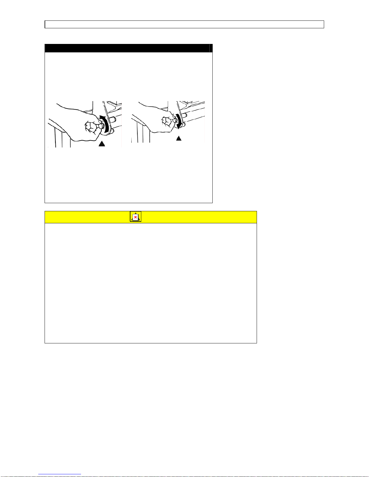
Step 11: Fine-tuning the roll media position
If the guide line (holes) can be seen, the roll media must be moved to the right.
If the guide line (holes) is hidden, the roll media must be moved to the left.
• Turn the scroller receiver screw counterclockwise to move the roll media to the right
(when standing in front of the printer).
Page 47

Preparing for a job Operation Instructions Rockhopper Printer
Page
47
AP-75024 Rev. 1.2. – 18/08/2002
• Turn the scroller receiver screw clockwise to
move the roll media to the left (when standing
in front of the printer).
Important:
• The guide line (holes) is a guide.
There is a possibility of a jam if the pressure roller is not holding the
left edge of the media and the pressure roller is near the right edge.
Either hold the left edge of the media completely with the pressure
roller or slide it so that the pressure roller is about 5 mm away from
the right edge of the media and the right edge of the media within 5
mm to the left or right of the guide line (holes).
Step 12:
• Check if the roll media has been installed correctly.
• Lower the media hold lever and close the cover.
• The head moves automatically and detects the media size.
• The display will show the following message during loading:
• After performing its media loading sequence (± 30 seconds) the printer displays the
following message:
Important:
• If the roll media has not been fed straight or incorrectly,
messages such as, “media error” or “media jam error” are
shown on the display. If this is the case, reload the media
following the instructions above.
ConfirmPaperKind
Plot OK
Page 48

Preparing for a job Operation Instructions Rockhopper Printer
Page
48
AP-75024 Rev. 1.2. – 18/08/2002
Step 13:
During the media detection sequence, check if the media runs straight. After media
detection, check the position of the right side of the roll media. If the position is almost on
the same line as it was before closing the cover, media loading was performed
successfully. If after the media detection sequence, the roll media position is not on the
same position as it was before closing the cover, repeat the instructions from steps 8 and
9 for installing the media.
Note:
Removing roll media
Step 1:
After printing, open the cover, tilt the media hold lever UP and wind up
the roll media.
Step 2:
Stand behind the printer. Unlock the scroller
receiver by pressing the lock lever down.
You can now lift the right side of the scroller
and remove it from the printer.
Step 3:
Remove the roll media by gently pushing the roll media off the scroller via
the moveable flange side.
At no times drop the scroller end-caps on the floor as this might damage
the scroller end-caps and reduce media tracking or loading problems.
3. Loading media in combination with the Roll Take-Up System.
Step 1 :
Open the cover and put the hold lever in the UP position by tilting it up(wards).
Page 49

Preparing for a job Operation Instructions Rockhopper Printer
Page
49
AP-75024 Rev. 1.2. – 18/08/2002
Step 2 : Selecting roll take-up system
• Press the Media-key to select
media loading sequence with roll
take-up system (Both LEDs ON).
• By pressing the key you will see the
LEDs alternate between three
choices (sheet, roll and take-up).
Now select roll take-up loading
sequence (both LEDs ON).
Step 3 :
Take an empty cardboard core. Slide the empty cardboard roll over the scroller of the roll
take-up system.
Note :
Notice that one flange is fixed. A warning sticker is attached near the
flange. Do not remove this flange.
Step 4 :
Take your roll of media.
Step 5 :
Remove the moveable flange from the
scroller by pulling it off.
Movable Flange
Step 6 : Load the media onto the scroller.
Feed the scroller through the media core.
Gently but firmly press the roll media over the fixed flange.
Slide the moveable flange over the scroller and firmly press the flange inside the roll media
core.
Page 50

Preparing for a job Operation Instructions Rockhopper Printer
Page
50
AP-75024 Rev. 1.2. – 18/08/2002
1 = Fixed flange
2 = Media winding direction
Note :
• Do not drop the media roll over the scroller as this might damage
the scroller end caps. Damaged end caps may cause media
tracking problems.
• All Mutoh recommended roll media are rolled up with the printable
side facing the outside, so that you can load the roll media easily.
Step 7: Installing the scroller slip ring
Install the scroller slip ring onto the scroller. Slide the scroller slip ring on the left side of
the scroller (side with fixed flange).
Step 8 : Installation of the scroller.
Install the scroller as follows :
a) Stand at the back side of the printer, holding the scroller with the fixed flange side in
your left hand.
b) Slide the scroller (left side) into the scroller receiver, as shown in the illustration.
c) Push the scroller (Right side – movable flange side) down into the right scroller
receiver. You will notice it dropping nicely into place.
Page 51

Preparing for a job Operation Instructions Rockhopper Printer
Page
51
AP-75024 Rev. 1.2. – 18/08/2002
Step 9: Locking the scroller slip ring
Lock the scroller by sliding the scroller slip ring onto the scroller rollers. The scroller slip
ring will prevent unwinding of the roll media from the scroller when roll media is still not
loaded in the machine.
Step 10 : Loading roll media.
Pull some media off the roll, feed it into the media feed gap
and between the pressure rollers and the drive roller.
Pull out the media at the front side and make sure at least 0.5
meters hangs out in front of the printer.
Caution :
When you load roll media from the back, be careful not to hurt yourself by
touching the pressure roller system.
Step 11 : Checking the position of roll media.
Turn the scroller by hand and wind up several turns of roll media. As you wind up the
media, check the relative positions of the drive roller on the right and the right hand edge
of the roll media. It is normal if with the roll media pulled tight, the portion that is being
wound and the portion that was unwound are straight and the right hand side edge of the
media is on the guide line. If this is not the case, adjust the position of the roll media in
accordance with step 9.
Page 52

Preparing for a job Operation Instructions Rockhopper Printer
Page
52
AP-75024 Rev. 1.2. – 18/08/2002
Guide line (holes) can be seen Guide line (holes) is hidden
Step 12 : Fine-tuning the roll media position.
If the guide line (holes) can be seen, the roll media must be moved to the right.
If the guide line (holes) is hidden, the roll media must be moved to the left.
• Turn the scroller receiver screw counterclockwise to move the roll media to the right
(when standing in front of the printer).
• Turn the scroller receiver screw clockwise to
move the roll media to the left (when standing
in front of the printer).
Important:
• The guide line (holes) is a guide.
There is a possibility of a jam if the pressure roller is not holding the
left edge of the media and the pressure roller is near the right edge.
Either hold the left edge of the media completely with the pressure
roller or slide it so that the pressure roller is about 5 mm away from
the right edge of the media and the right edge of the media within 5
mm to the left or right of the guide line (holes).
Page 53

Preparing for a job Operation Instructions Rockhopper Printer
Page
53
AP-75024 Rev. 1.2. – 18/08/2002
Step 13 :
• Before lowering the media hold lever, hold the media on the front side and turn the
media feeding scroller slightly backward, making sure that there is an even tension
across the full media width.
• Lower the media hold lever and close the cover.
• The head moves automatically and will search for the left and right edge of the media
being loaded.
Important :
If the roll media has not been fed straight or incorrectly, messages such
as “Stuck Media error” or “Take out paper” are shown on the display. If
this is the case, reload the media following the instructions mentioned
above.
Step 14 :
In the MENU “Function” of your printer, set media cut to OFF.
Step 15 :
Feed the media forward by pressing the SHIFT &
ADVANCE keys simultaneously until the media
reaches the cardboard core on the take-up
system.
Step 16 :
Fix the media on the cardboard core by means of self-adhesive tape strips in the middle
and on the left and right side.
Note :
First attach the middle of the media on the cardboard core to avoid
slipping of the media.
Step 17 :
Feed the media slightly forward (using SHIFT & ADVANCE) and wind it up on the take-up
system.
Now you are ready to start printing.
Page 54

Preparing for a job Operation Instructions Rockhopper Printer
Page
54
AP-75024 Rev. 1.2. – 18/08/2002
Once the printer has printed as much as shown on the figure below, the sensors will be
activated and the take-up system will start winding up the media.
Once your print is finished and dry you can wind up your print via a manual feed button.
If you want to sheet off the print push the cancel button for 2 seconds and confirm the
sheet-off request.
If you want to wind up or wind off your print you can do this via the forward / reverse
button.
Page 55

Preparing for a job Operation Instructions Rockhopper Printer
Page
55
AP-75024 Rev. 1.2. – 18/08/2002
USING PRE- AND POST-HEATERS.
Use the Pre- and Post-heater for uncoated or slow-drying media. With the Heaters you
can get a wider range of media compatibility.
When using the heaters set it on the maximum temperature.
Important :
Depending on the use of media, it is possible that media starts to curl.
If this is the case, lower the temperature.
USING ECO-SOLVENT INK
• Before installing or changing to Eco-Solvent ink, perform a Head Wash. The tubes and
heads must be clean. Use the special Eco-Solvent Transition Liquid.
• Once you have worked with eco-solvent inks, it is forbidden to change to another ink
type.
• Prints are UV- and water-resistant for up to three years outdoors (*). Lamination is
required for heavy-duty applications.
• No need for special ventilation or environmental equipment.
(*) Accelerated weather tests predict up to 3 years outdoor durability. Outdoor durability is
location and application dependant.
USING PIGMENTED INK
• Pigmented ink tends to dry faster than dye ink. Make sure to clean the head cleaning
wiper regularly in order to avoid head clogging.
(See section: cleaning head cleaning wiper)
• Pigmented inks at all times require the ink density to be set to NORMAL. These inks
are not compatible with FAINT nor with THIN ink density mode which both use the
micro-dot printing mode.
• If you have a RIP software in which media pr ofiles are available for the Mutoh ink/media
combination, the software normally should disable the micro-dot mode as soon as a
profile for pigmented ink is selected. It is best however, always to double check this.
Page 56

Preparing for a job Operation Instructions Rockhopper Printer
Page
56
AP-75024 Rev. 1.2. – 18/08/2002
PRINT ORIGIN CONTROL.
The Origin-Reset function allows you to move the horizontal origin, effectively changing
the offset versus the right border.
The value can be set ranging from 0 mm to the media width minus the left and right
margins (20 mm), in 1mm increments. The inclusion of this function allows you to
manually nest images, working in conjunction with the Media Feed Reverse button on the
control panel of the printer (See Control Panel Section below).
In a typical application, an image narrower than the media width would be printed flush
with the right margin. After printing, the media can be fed back into the printer using the
Media Feed Reverse button. Then, the horizontal origin can be moved using the OriginReset function in the User Menu under the Functions submenu. Using this method, the
next image would automatically be printed to the left of the first image, rather than behind
it, thus avoiding excess media waste.
Note, however, that once set, the Origin-Reset function will remain set until changed again
or reset to zero by the user.
Plot OK
Step 1 :
To enter the Menu system, press the
[MENU] key.
* Menu * Command >
Step 2 :
The key contents changes according to the
yellow section on the outside of the control
panel. Bring up the “Command” menu by
pressing the [Menu up] key or [Menu
Down] key.
Page 57

Preparing for a job Operation Instructions Rockhopper Printer
Page
57
AP-75024 Rev. 1.2. – 18/08/2002
* Menu * Command >
Step 3 :
Press the [ENTER] key to confirm the
“Command” menu and shift to the next
level.
OriginReset : No
Step 4 :
Bring up the “OriginReset” item by pressing
the [Menu up] key or [Menu Down] key.
OriginReset : Yes
Step 5 :
Press the [Value/+] or [Value/-] key to
select “Yes” or “No”.
Origin : Init
Step 7 :
Press the [Value/+] or [Value/-] key to
select “new origin” or “Initialisation”.
Origin : New>
Step 8 :
To select a new origin select “New>” and
press the [ENTER] key to confirm.
Offset : 0
Step 9 :
Set a new origin (0 to media width minus 20
mm) and press the [ENTER] key to confirm.
* Menu * Command >
Step 10 :
Do not press any other keys for 3 minutes
or press [BACK] key
Plot OK
Step 11 :
The permanent ONLINE-status display is
restored.
Note :
Once set, the Origin-Reset function will remain set until it is reset to zero
or until it is changed by the user.
Page 58

Preparing for a job Operation Instructions Rockhopper Printer
Page
58
AP-75024 Rev. 1.2. – 18/08/2002
MICRO-BANDING ELIMINATION.
The nominal paper movement accuracy is ± 0.1 percent, or ±1 mm per meter of moving
distance. Different media types may show different behavior and when the paper
movement error exceeds the target specification, banding can occur. This banding can
take the form of thin dark horizontal bands, or thin white horizontal bands.
If the above happens, these bands will occur in both bi-directional and unidirectional print
modes. Thin dark bands indicate that the printer firmware is under-compensating and that
print swaths are overlapping on the edges. Alternatively, thin white lines indicate that the
printer firmware is over-compensating, and that print swaths are not perfectly butted
together.
The media feed micro step adjustment option gives the user the ability to steer the step
compensation algorithm. To eliminate micro-banding, you can enter a positive or negative
percentage of compensation, (± 3.00 percent), in 0.01 percent increments.
A positive value will extend the step and compensate for overlapping print swaths; a
negative value will shorten the step and compensate for non-butting print swaths. Some
trial and error testing is typically required to find the optimum value for any given media
type.
Plot OK
Step 1 :
To enter the Menu system, press the
[MENU] key.
* Menu * Command >
Step 2 :
The key contents change to the yellow
section on the outside of the control panel.
Bring up the “Function” menu by pressing
the [Menu up] key or [Menu Down] key.
Page 59

Preparing for a job Operation Instructions Rockhopper Printer
Page
59
AP-75024 Rev. 1.2. – 18/08/2002
* Menu * Function >
Step 3 :
Press the [ENTER] key to enter the
“Function” menu and shift to the next level.
Step Adjustment : Change
Step 4 :
Bring up the “Step Adjustment” item by
pressing the [Menu up] key or [Menu
Down] key.
Step Adjustment : Clear
Step 5 :
Press the [Value/+] or [Value/-] key to
select “Change” or “Clear” and press
ENTER.
Step Adjustment : 0.00%
Step 6 :
When pressing “Change”, enter the new
value using the [VALUE/+] / [VALUE/-]
keys. Using the [MENU UP] / [MENU
DOWN] keys, you can select which digit you
want to change. The value can be changed
in 0.01% increments.
Press [ENTER] to confirm the new value.
Step Adjustment : Change
Step 7 :
If no other items are to be changed, press
the [BACK] key.
* Menu * Function >
Step 8 :
Do not press any other keys for 3 minutes
or press [BACK] key
Plot OK
Step 9 :
The permanent ONLINE-status display is
restored.
Page 60

Preparing for a job Operation Instructions Rockhopper Printer
Page
60
AP-75024 Rev. 1.2. – 18/08/2002
Note :
To find the optimum correction value for a certain media, you will need to
go through a series of test cycles. Preferably send to the plotter a small
test image such as a neutral grey square (between 50% and 70% Grey)
and check the micro-banding as described above. Make a note of your
correction value for a certain media type, as the required value will always
be the same for this media type.
Note :
Before using this function, always perform a nozzle-check to see if all
nozzles are firing correctly. Nozzles which are not firing or misfiring might
mislead you when entering correction values.
Page 61

Daily Maintenance Operation Instructions Rockhopper Printer
Page
61
AP-75024 Rev. 1.2. – 18/08/2002
DAILY MAINTENANCE
REPLACING THE INK CASSETTES
When the Rockhopper printer indicates or insert or replace
the ink cassette(s) as soon as possible.
When the indication is , prepare to have new ink cassettes available.
Step 1:
If the display shows , pull out the empty or in-operational ink cassette.
Note:
• Each sign [Y] [M] [C] [K] indicates:
Y : Yellow, M : Magenta, C : Cyan, K : Black.
• [O] indicates: Orange or Light Cyan
• [G] indicates: Green or Light Magenta
Step 2:
Unpack a new ink cassette.
Note:
• Only use original Mutoh ink cassettes.
• For each cassette, there is a correct place and a correct inserting
direction.
• Open the ink cassette just before inserting it into the slot.
• Use ink cassettes within two years from the date printed on the
package.
• Replace your ink cassettes at least every 6 months.
Step 3:
Insert a new ink cassette into the slot.
Step 4:
When insertion / replacement of ink cassettes has been performed well, the display will
show the following message if media is loaded and the printer is ONLINE:
No Ink No Cartridge
Ink low
Plot OK
No Ink
Page 62

Daily Maintenance Operation Instructions Rockhopper Printer
Page
62
AP-75024 Rev. 1.2. – 18/08/2002
SWITCHING BETWEEN DYE INKS AND PIGMENTED INKS OR
CHANGING TO ECO-SOLVENT INK.
Use the INK CHANGE procedure to switch from DYE ink to PIGMENTED ink or from
PIGMENTED ink to DYE ink. Use the INK CHANGE procedure to switch from Dye or
Pigmented Ink to ECO-SOLVENT INK.
Important :
After using Eco-Solvent ink it is not possible to change to other type of ink
(pigmented and dye Inks).
Before installing and changing to Eco-Solvent ink, the machine needs to
go through a cleaning cycle with special Eco-Solvent transition liquid.
When using this function, cleaning cassettes need to be installed to the cassettes slots.
Plot OK
Step 1 :
To enter the Menu system, press the [MENU]
key.
* Menu * Command >
Step 2 :
The key contents change to the yellow section
on the outside of the control panel. Bring up the
“Utility” menu by pressing the [Menu up] key or
[Menu Down] key.
* Menu * Utility>
Step 3 :
Press the [ENTER] key to enter the “Utility”
menu and shift to the next level.
InkChange : No
Step 4 :
Bring up the “InkChange” item by pressing the
[Menu up] key or [Menu Down] key.
InkChange : Yes
Step 5 :
Press the [Value/+] or [Value/-] key to select
“Yes” and press ENTER.
Change Waste Ink
Step 6 :
Empty the waste ink bottles.
Change Tank ? Yes
Step 7 :
Press the [Value/+] or [Value/-] key to select
“Yes” and press ENTER.
Page 63

Daily Maintenance Operation Instructions Rockhopper Printer
Page
63
AP-75024 Rev. 1.2. – 18/08/2002
ConfirmChange Yes
Step 8 :
Press the [Value/+] or [Value/-] key to select
“Yes” and press ENTER.
Remove Cart
Step 9 :
Remove ink cartridges from the slot.
Set Wash Cart
Head Wash
Step 10 :
Insert the cleaning cartridge to the ink cartridge
slots. Use the special Eco-solvent Transition
Liquid when changing to Eco-solvent ink.
The head wash starts when the cleaning
cartridge is inserted. The cleaning period is
approximately 15 minutes.
Remove Wash Cart
Step 11 :
Remove the cleaning cartridge from the slot.
Head Wash
Step 12 :
The rest of the cleaning fluid in the printer unit is
discharged when the cleaning cartridge is
removed.
Change Waste ink
Step 13 :
Empty the waste ink bottle from the printer unit.
Change Tank ? Yes
Step 14 :
Press the [Value/+] or [Value/-] key to select
“Yes” and press ENTER.
ConfirmChange
Yes
Step 15 :
Press the [Value/+] or [Value/-] key to select
“Yes” and press ENTER.
[YMCK] Discharged
Step 16 :
If the cassettes that have been removed are
DYE ink cassettes, now insert PIGMENTED ink
cassettes or ECO-SOLVENT ink cassettes.
If the cassettes that have been removed are
PIGMENTED ink cassettes, now insert DYE ink
cassettes or ECO-SOLVENT ink cassettes.
Page 64

Daily Maintenance Operation Instructions Rockhopper Printer
Page
64
AP-75024 Rev. 1.2. – 18/08/2002
Important :
After using Eco-Solvent ink it is not possible to change to other type of ink
(pigmented and dye Inks).
Ink Refill 4M
Ink Refill 3M
Ink Refill 2M
Ink Refill 1M
Ink Refill 0M
Ink Refill 4M
Ink Refill 3M
Ink Refill 2M
Ink Refill 1M
Ink Refill 0M
Step 17 :
The initial fill is executed when installing
cartridges.
The display will show the following messages :
Plot OK
Step 18 :
After filling, the display will show the following
message :
Note :
• The cleaning cartridge is one time use only.
• Only recommended ink cassettes can be used. The also need to be
turned in the proper direction for insertion.
• Ink cassettes should be used within two years of the date that is
printed on the package. Cassettes that have been loaded into the
printer should be replaced within six months.
Page 65

Daily Maintenance Operation Instructions Rockhopper Printer
Page
65
AP-75024 Rev. 1.2. – 18/08/2002
CLEANING THE HEAD CLEANING WIPER.
When the head is cleaned and the type of ink is changed frequently, waste matter clinging
to the cleaning wiper may cause the printing to become faint or blemished. In such case,
you should clean the cleaning wiper.
Step 1:
Switch off the power, lower the hold lever and bring the head to the middle.
Caution:
• Do not move the head with the hold lever up. The head and media
keeper blade may touch, causing damage and poor printing quality.
Step 2:
Clean the cleaning wiper backwards and forwards two or three times with the cloth for
cleaning the cleaning wiper.
1. Head cap unit
2. Cleaning wiper
Caution:
• Clean without your hand coming into direct contact with the head cap
unit, which is near the cleaning wiper. Otherwise oil may get on the
cleaning wiper and it will be unable to clean the head properly.
• Do not lift up the cleaning wiper when you are cleaning it. Otherwise it
is unable to clean the head properly.
• The cleaning wiper and its surroundings will be soiled with waste
liquid. Be careful not to dirty your hands and clothes.
Step 3:
Return the head to its former position at the right hand end of the printer.
Caution:
• The head may be damaged by drying ink, etc. if it is not returned to the
right hand end of the printer.
Page 66

Daily Maintenance Operation Instructions Rockhopper Printer
Page
66
AP-75024 Rev. 1.2. – 18/08/2002
REPLACING THE CUTTING BLADE
Depending on the kind of roll media used, paper dust gathers in the cutter slot and on the
cutter blade edge. This may cause bad sheeting off quality. In this case, replace or clean
the cutting blade or/and clean the cutter slot.
The cutting blade is a consumable item, so if the blade loses sharpness, replace it.
We recommend replacing the cutting blade regularly.
Caution:
The hold lever must be down.
Do not move the head with the hold lever up. The head and media
keeper may touch, causing damage and poor printing quality.
Step 1:
Switch off the printer and pull the printing head to the center of the printer.
Step 2:
Take out the cutting blade by pushing the cutter head down and rotating the cutter arm
towards you.
Either clean the cutting blade with a dry cloth or replace it.
Caution:
• There is a spring fitted in the hole of cutter head. Be careful not to
loose it while replacing the cutting blade.
Step 3:
Insert a new cutting blade in the hole of the cutter head. While pushing the cutting blade
down, put the cutter arm back over the cutting blade. A cutting blade can only be inserted
in one direction.
Page 67

Daily Maintenance Operation Instructions Rockhopper Printer
Page
67
AP-75024 Rev. 1.2. – 18/08/2002
Caution:
• The edge of the cutting blade is very fragile, while replacing it, handle
it with care.
Step 4:
Put the head manually back into its capping position, and turn the power switch ON.
Note:
• Durability of the cutting blade may differ depending on the kind or
thickness of the media and used environment. We recommend
purchasing a spare cutting blade so that you always have a spare
blade at hand.
Important:
If you don’t have a new sheet-off blade available to replace your
blade, you can temporarily switch off the automatic sheet-off.
Press menu À until you see Function.
Press Enter Function Ink Dry Time.
Press menu À until you see “Media Cut : ON”
Press value + or value -: “Media Cut : OFF”
Press Enter
Press Back ½½ 2 times to go back to ONLINE Level.
Page 68

Control Panel Operation Instructions Rockhopper Printer
Page
68
AP-75024 Rev. 1.2. – 18/08/2002
PERIODICAL MAINTENANCE
You have to change some parts of the Rockhopper printer to obtain a good quality.
Please refer to the tables for an overview of periodical maintenance.
You will notice that the X-marks indicate a renewal of the mentioned part(s) after this many
months.
You have to change the absorbents every week.
IMPORTANT :
Note that the x-marks in month 6 and month 12 are only to be done by
authorized Mutoh technicians.
Maintenance cycle on Rockhopper 48 “
Monthly
Description Qty
1 2 3 4 5 6 7 8 9 10 11 12
Print Head 2 X
Flush Box Spare Part 1 X X
Wiper 1 X X
Sensor on ext. Waste Bottle syst. 1 X
Maint. Station GA Assy RJ-6100 1 X X
Waste Connection tube small 2 X X
Dust removal in fan area - X
Cleaning maintenance Station - X X
Cleaning bottle 1 X X
Blade on press roller 4100/6100P 18 X
F-absorbent 1 RJ-4100 4 WEEKLY
Maintenance cycle on Rockhopper 62 “
Monthly
Description Qty
1 2 3 4 5 6 7 8 9 10 11 12
Print Head 2 X
Flush Box Spare Part 1 X X
Wiper 1 X X
Sensor on ext. Waste Bottle syst. 1 X
Maint. Station GA Assy RJ-6100 1 X X
Waste Connection tube small 2 X X
Dust removal in fan area - X
Cleaning maintenance Station - X X
Cleaning bottle 1 X X
Blade on press roller 4100/6100P 24 X
F-absorbent 1 RJ-4100 4 WEEKLY
Page 69

Control Panel Operation Instructions Rockhopper Printer
Page
69
AP-75024 Rev. 1.2. – 18/08/2002
UNDERSTANDING THE CONTROL PANEL &
PRINTER CONTROLS
GUIDED TOUR AROUND THE CONTROL PANEL
Your printer is equipped with a direct access control panel, meaning that all frequently
used functions can be addressed directly from the keyboard.
Nr.
Key Description
1. Data LED :
The DATA LED monitors DATA status :
• LED ON indicates data is being received.
• LED FLASHING means data is being processed.
2. Error LED :
The ERROR LED is ON after an ERROR has
occurred, to indicate a possible hazardous situation.
The LED will go out if the error is corrected or after
pressing the [CANCEL] key.
Page 70

Control Panel Operation Instructions Rockhopper Printer
Page
70
AP-75024 Rev. 1.2. – 18/08/2002
3. Cancel Key :
The [CANCEL] key is a special key, controlling both the
CANCEL FUNCTION as well as the ROLL MEDIA
sheet-off function.
Printer Condition Result by pressing
CANCEL
Idle Status
Roll media is cut at the
current position
Receiving Status
Process stops
Process Status
Buffer is cleared
Printing Status
Print is cancelled, buffer
is cleared, printed part is
cut-off.
To request a sheet-off, press cancel for 2 seconds
and confirm with [ENTER].
4. Cleaning :
- Pressing for 2 seconds initiates the cleaning
procedure.
- When pressed together with the [SHIFT] key,
(9) it initiates the head adjustment procedure.
- Go to the Previous Menu, when in menu-mode
operation.
- For advanced Cleaning Control, enter the menu
system and select submenu [Utility] – option
[Clean].
5. Quality / Speed :
- Pressing QUALITY / SPEED
will change the
output quality and speed. Each time the key is
pressed you will notice the LED indicator
showing the current status : High quality,
Normal and High Speed.
- The set-up can only be changed in idle status.
- When pressed together with [SHIFT] key (9)
outputs the Test Print.
- Go to the Next menu option, or increase a
parameter value when in menu-mode
operation.
- The LED indication is also influenced by data
coming from the RIP/driver software.
Page 71

Control Panel Operation Instructions Rockhopper Printer
Page
71
AP-75024 Rev. 1.2. – 18/08/2002
6. Resolution :
- Pressing RESOLUTION
will change the output
resolution between 360 DPI, 720 DPI or 1440
DPI. The set-up can only be changed in idle
status.
- When pressed together with the [shift] key (9)
it allows reverse manual roll feed.
- Select the previous menu option and decrease
a parameter value when in menu mode
operation.
- If both LEDs are ON simultaneously the plotter
operates in one of the 3 available 1440 dpi
modes (horizontal, vertical or diagonal).
- The LED indication is also changed by data
coming from the RIP software.
7. Media :
- Allows selection among roll, cut-sheet or
media take-up system support.
- When pressed together with the [shift] key
(9),
generates a nozzle check print.
- Accept a new setting when in menu mode or
enter a lower menu level.
8. Menu Mode Operation :
The Menu Mode Operation is used to change printer
settings and parameters. Menu Mode related buttons
are enclosed in the yellow area.
Page 72

Control Panel Operation Instructions Rockhopper Printer
Page
72
AP-75024 Rev. 1.2. – 18/08/2002
9. Shift-button :
- Shift button to activate Head Adjustment,
manual roll feed (forward or reverse), Nozzle
check print, Test print or Set-Up List.
- Back out of menu levels or switch back to
ONLINE level from top level (Menu mode
operation).
10. Menu :
- The Menu Mode Operation is used to change
printer settings and parameters.
- Press the [MENU] key to switch from ONLINE
status to menu mode operation.
- When pressed together with the [shift] key (9)
it allows forward manual roll feed.
11. Liquid Cristal Display :
16 characters LCD display which displays messages,
shows settings / values and allows menu-wise
control.
12. Vacuum :
- The Vacuum key allows you to reduce the fan
power when using very light media such as
synthetic paper or uncoated paper lighter than 70
g/m².
- When pressed together with the [SHIFT] key,
(9) it initiates a Set-up List and an adjustment
parameter plot.
Page 73

Control Panel Operation Instructions Rockhopper Printer
Page
73
AP-75024 Rev. 1.2. – 18/08/2002
Note :
• When the data light is ON (receiving) or blinking (processing), all the
keys are disabled, except the head cleaning key.
The keys will be operational in case of receiving data while you are in
the setup menu. The settings changes, however, will then only be
valid for the next printing job.
• Panel set up from the printer is only possible when no printing data or
processing data is sent to the printer.
• In menu mode operation, the shift key functions are not available.
Page 74

Control Panel Operation Instructions Rockhopper Printer
Page
74
AP-75024 Rev. 1.2. – 18/08/2002
HEATER SYSTEM CONTROL PANEL.
1 = Controls Front Heater
2 = Controls Rear Heater
3 = Power Switch
Power Switch:
Control for power ON or OFF the Heater System.
Controls Front Heater:
Set temperature for the front heater. Real (RT) and set (ST) temperature are displayed on the LCD screen.
The maximum temperature is 50 °C. By pushing the buttons you can select an appropriate temperature.
Controls Rear Heater:
Set temperature for the rear heater. Real (RT) and set (ST) temperature are displayed on the LCD screen.
The maximum temperature is 50 °C. By pushing the buttons you can select an appropriate temperature.
Page 75

Control Panel Operation Instructions Rockhopper Printer
Page
75
AP-75024 Rev. 1.2. – 18/08/2002
MENU MODE OPERATION.
The Menu Mode Operation is used to access settings, which cannot be controlled via the
direct access keys. As soon as media is loaded, the printer is ONLINE and ready to
receive data.
In case no media is loaded, the printer is OFFLINE.
To enter the MENU MODE proceed as follows :
1. Press the MENU-key.
2. To select the next/previous menu item press Menu Down ↓ / Menu Up ↑.
3. To select the next/previous option or value press value + / value -.
4. To accept a new setting or enter a next menu level press ENTER.
5. To return to a previous menu level, or exit the menu system press Back ←.
In case Media is loaded, exiting the top menu level will switch the printer back to ONLINE.
Page 76

Control Panel Operation Instructions Rockhopper Printer
Page
76
AP-75024 Rev. 1.2. – 18/08/2002
Menu Structure – overview.
Command MH-GL2 / MHGL, GL2 /
RTL-PASS
Printer command language
selection
PlotArea Normal / Expend Set-up hard clip area
depending of media size.
Position P1 / Full / LL Set-up initial pen position in
MH-GL, GL2 and MH-GL2.
Terminat Special / Normal Command Language
terminator selection.
Resolut 720dpi / 360dpi / 300dpi Select logical resolution.
OnlineTimer Off / 10s / 20s / 30s / 40s
/ 50s / 60s / 90s / … /
780s / 800s
In case of intermittent data
flow, determines time-out to
finalize plot.
Overwrite Last / Mix Set-up control of
overlapping areas.
Command
OriginReset No / Yes Allows manual nesting
when combined with
backward feed.
InkDryTime 0 sec to 5 sec to 30 sec
to 60 min.
Set-up ink drying time
before sheet-off occurs.
Halftone Quality / Speed / Thin Select method of pseudo-
tone processing.
KCMY→KMY
Yes / No Reserved for future use.
CMY→Black
Yes / No Allow mixed black (CMY) or
not.
KYCMYK No / Yes Reserved for future use.
Scale 25% to 100 % to 400% Expand or reduce print
data.
Mirror Off / Y On Reverse printing set-up.
Direct. Command / MAX-MIN Media size determined by
Page size Command or by
plot data.
Cut Position Data / Standard Specify cutting position on
roll media following data or
standard media size.
MediaCut Auto / Off / Manual Automatic sheet-off set-up.
Copy 1 to 99 Set-up number of copies.
InkDensity Normal / Micro Select Normal or Micro dot
drop size in function of
media & ink type.
Dist.Adj No / Clear / Change /
Confirm
Plot distance adjustment.
Function
StepAdj Change / Clear Micro-banding elimination
via microstep adjustment.
Mode Bi Centro / Centro Select between uni-
directional and ECP high
speed.
Centro
Timing A – B / B – A Select ACK timing for
BUSY state.
Network IP Address 000.000.000.000 to
192.034.041.015 to
255.255.255.255
ErrorDisplay Off / On Show or hide simple error.
No
Initialize printer set-up.
Yes InitialAll No / OK Initialize printer set-up.
InitialCommand No / OK Initialize printer set-up.
InitialFunct No / OK Initialize printer set-up.
InitialCentro No / OK Initialize printer set-up.
Initialize
InitialNetwork No / OK Initialize printer set-up.
Dump Start – End / All (Cancel
with CANCEL-key)
Set-up data dump mode.
Wash Starts manual head wash
before ink type switching.
Normal Starts a NORMAL cleaning Clean
Powerful Starts a POWERFUL
cleaning
No
Fill
Yes
Starts a Ink Fill Sequence
Ink Change No / Yes Starts ink Change
Procedure
Online
Utility
Maintenance
Rec.
Prints maintenance record.
Page 77

Daily Maintenance Operation Instructions Rockhopper Printer
Page
77
AP-75024 Rev. 1.2. – 18/08/2002
PRINT MODES ACCESSIBLE VIA THE CONTROL PANEL.
The following print modes are predefined as Draft, Normal and Quality. These modes may
be overwritten from the host computer using the printer manager commands.
Panel LEDs Print Mode m²/h Output Resolution (dpi)
360 – Draft 1-Pass / Bi-directional 14.49 360 x 180
360 – Normal 1-Pass / Unidirectional 10.87 360 x 180
360 – Quality 2-Pass / Unidirectional 5.43 360 x 360
720 – Draft 2-Pass / Bi-directional 7.25 720 x 360
720 – Normal 2-Pass / Unidirectional 5.43 720 x 360
720 – Quality 2-Pass / Unidirectional 2.72 720 x 360
1440 – Draft 8-Pass / Bi-directional 1.81 1440 x 1440
1440 – Normal 8-Pass / Unidirectional 1.81 1440 x 1440
1440 – Quality 16-Pass / Unidirectional 0.68 1440 x 1440
Page 78

Daily Maintenance Operation Instructions Rockhopper Printer
Page
78
AP-75024 Rev. 1.2. – 18/08/2002
 Loading...