

Page 1

MAINTENANCE
MANUAL
Eco-Solvent Inkjet Printer
Rockhopper 46/62
Rockhopper: AP-74016, Rev:1.0
Page 2

CON1000
Model Name: Rockhopper-46/62
CON1000
Model Name:Rockhopper-46/62
Introduction
Introduction
This equipment is Class 1 communications equipment (communications equipment
to be used in commercial and industrial areas) and conforms to Voluntary
Communications Control Institute (VCCI) standards for data processing and other
equipment for the prevention of radio wave interference in commercial and industrial
areas.
Therefore, if it is used in or near a residential area, it may cause interference with
radio and television reception.
It should be used correctly in accordance with the operation manual.
■ Concerning interference with reception
Since this product emits weak radio waves, if it is not installed and used correctly
and is thought to be causing interference with radio and television reception, this
may be prevented by trying a combination of the following measures:
• Try changing the orientation of the receiving antenna and feeder.
• Try changing the orientation of this product.
• Change the distance between the receiver and this product.
• Try using different power supply systems for the receiver and this product.
■ Trademarks included in this manual
• MUTOH, Model Name:Rockhopper-46/62, MH-GL, MH-GL/2, MH-RTL
are trademarks or trade names of Mutoh Industries Ltd.
• HP, HP-GL, HP-GL/2, HP-RTL, HP759X, HP758X, C2848 are trademarks or
trade names of the Hewlett Packard Company.
• Centronics and Bitronics are trademarks or trade names of the Centronics Data
Computer Company.
• Windows 3.1, Windows 95, Windows NT 3.51, Windows NT 4.0, MS-DOS are
trademarks or trade names of the Microsoft Corporation
• Other names of products and companies are the trademarks or trade names of
each relevant company.
This manual contains basic technical details necessary for marketplace servicing to
maintain product quality and performance of Model Name:Rockhopper-46/62 printer.
Model Name:Rockhopper-46/62 printer is equipped with a self-diagnostic program
that will be of service for adjusting and checking whenever a fault is detected or
during maintenance.
This manual contains all the basic items but actual maintenance work should be
undertaken only after a thorough understanding of the functions, operations and
movements has been gained from the operation manual and by other means.
Please note that there may be occasions where the name of a part used in the
explanation in this manual differs from the name of that same part that is used in the
operation manual or in the parts list.
Published by Mutoh Europe,
Archimedesstraat 13, 8400 Oostende Belgium
Copyright February 2002, Mutoh Europe All rights reserved.
CAUTION:
• The details of this product and the contents of this manual are
protected by copyright held by this Company and, except for
legitimate use by individuals, unauthorized copying, reproduction
or distribution in whole or part is forbidden.
• Details contained in this manual may be subject to future alteration
without notice.
• Details contained in this manual are believed to be correct but
please contact this Company or a dealer if an error is suspected
or a point is not clear.
• In no event will this Company be responsible for the consequences
of using this product or this manual.
Page 3

CON1010
Model Name:Rockhopper-46/62
CON1010
Model Name:Rockhopper-46/62
Some Thoughts on Maintenance Work
Some Thoughts on Maintenance Work
1. Algunas ideas sobre el trabajo de Mantenciónn
La mantencion cae en dos categorias, Full mantencion y mantencion preventiva
, both of which are aimed at stable operation of the equipment that has been delivered to the user.
Las posibilidades de mantencion deben considerar.
• In principle, fault maintenance and protective maintenance are both carried out by the
one person.
• Both fault maintenance and protective maintenance involve the bringing of maintenance
parts.
• The cooperation of the user/operator is used effectively.
2. Protective maintenance work
La mantencion periodica esta designed to provide the user con mas estabilidad operation of the
equipment and involves the periodic cleaning and replacement of replacement parts. Basic
ideas on protective maintenance include:
• Adhere strictly to preventive maintenance periods.
• In a case of carrying out preventive maintenance, gain the approval of the user before-
hand.
• Don’t press preventive maintenance on the user.
3. Fault maintenance work
A fault will hold up the user’s work and must be remedied quickly. The following are some
basic ideas on fault maintenance:
3-1 If it is not solved by the primary consultation, take the necessary maintenance items
and make an on-site visit.
• Assemble the necessary maintenance parts from the matrix map
• At the user’s premises, first check the symptoms.
• Proceed with maintenance work in accordance with the fault tracing procedure.
• After the repair work is finished, be sure to check again by testing in accordance
with the test procedure.
3-2 If repair is not possible even though all the work has been done in accordance with
the fault tracing procedure:
• Contact the Sales Support Groups in your local distributor.
4. The need for user/operator cooperation
! CAUTION: The user cannot be compelled to do the following!
Asking the user/operator to cooperate is not a matter of having the user do the maintenance for you but it is necessary in order to have the equipment working more efficiently
and for having faults rectified quickly.
Actually, even when you do ask for the user’s cooperation, instead of a simple acknowledgement you will usually get doubts and quibbles such as “I’m paying for maintenance”,
“I’m not familiar with the equipment” and “it only benefits the manufacturer.”
However, you must try to persuade the user/operator to cooperate by explaining that doing
daily inspections will give better printing quality and giving you all the fine details of a fault
means that the fault will be rectified quickly.
The following explains the items you need in order to understand fault conditions in detail:
• Check error messages
• Check user’s usage conditions
• Output from diagnostic pattern
• Output from setup lists
• Retest after changing settings
• Probability of recovery by implementing daily inspections.
Page 4
CON2000
Model Name:Rockhopper-46/62
CON2000
Model Name:Rockhopper-46/62
Precautions For Maintaining This Printer
Precautions For Maintaining This Printer
PRECAUTION 1 Head Cleaning
Head cleaning (see REP1620) must be carried out when this printer is to be transported by truck (see CON6000) and when the following parts are to be replaced.
< Replacement parts > Head, Damper, Head Cable, Cartridge Frame Assembly,
Ink Tubes
PRECAUTION 2 Head Cleaning Jig
When the head cleaning jig is to be used, fill the jig’s 100 cc bottle with at least 50
cc of cleaning fluid and use it with the cap loosened.
If head cleaning is done with the cap tightened, ink will flow back into the 100 cc
bottle.
When you have finished head cleaning, return the remaining cleaning fluid from the
100 cc bottle to the 500 cc cleaning fluid bottle (JD-42054).
PRECAUTION 3 Printing After Initial Filling
On rare occasions, printing quality may be unstable if printing is carried out immediately after initial filling.
If this occurs, switch off the power and wait for at least 30 minutes before trying to
print again.
PRECAUTION 4 Thorough Waste Fluid Bottle Replacement
When the following tasks have been carried out,drain the waste fluid bottle.
1. After head cleaning and initial filling.
2. When it was not possible to capture main board assembly backup parameters.
PRECAUTION 6 Take Care When Inserting Head Cable and Y Cable
PRECAUTION 7 Ink and Cleaning Fluid Conduct Electricity
When the print head assembly, head board assembly and main board assembly
have been replaced, be careful to insert the head cable and Y cable straight to the
back and don’t forget to lock the connectors.
(The connectors fitted with locks are J207 and J208 on the head board.)
If the cables are inserted obliquely or power is applied without locking the connectors, there is a risk that the main board assembly may be damaged and it will be
impossible for ink to be ejected.
Ink and cleaning fluid will conduct electricity.
If there is ink or cleaning fluid on the connectors of the head or head cables when
power is applied, there will be a short circuit which may lead to all sorts of damage.
If there is ink on the contacts of the connector, wipe it off with alcohol or ethanol and
allow to dry thoroughly before reconnecting.
PRECAUTION 5 Maintenance Unit Tubes
If you can not lower the maintenance unit cap assembly and the cap assembly and
pump assembly have been replaced:
• When the two tubes from the pump assembly are being connected to the cap
assembly, turn them clockwise through 45 to 90 degrees as you insert them.
Page 5
CON3000
Model Name:Rockhopper-46/62
CON3000
Model Name:Rockhopper-46/62
Contents
Contents
Rockhopper-463 Rockhopper-62
Introduction CON 1000 CON 1000
Some Thoughts on Maintenance Work CON 1010 CON 1010
Precautions For Maintaining This Printer CON 2000 CON 2000
Contents CON 3001 ~ 3 CON 3007 ~ 9
How to use the Maintenance Manual CON 4000 CON 4000
Trouble-Shooting Lists TRB 0000 TR B 0000-3
Matrix Map MAP 0000 MAP 0000-3
Fault-Tracing Procedure EXA 0000 EXA 0000-3
Replacement and Adjustment Procedures REP 0000 REP 0000-3
Fundamental Knowledge GID 0000 GI D 0000-3
Stored Test Patterns PAT 0000 PAT 0000-3
Self-Diagnosis Functions BAC 0000 BAC 0000-3
Maintenance Parts CAT 0000 CAT 0000-3
Page 6

CON3001
Model Name: Rockhopper-46
Model Name: Rockhopper-46
Rockhopper-463 Contents 1
Rockhopper 46 inch
Trouble-Shooting Lists TRB0000
• When Message is Displayed TRB1000
- How to Use LEDs to Check CPU System and Mechanical System Faults TRB1001
• When Message is not Displayed
- Initialization, Media Feed, Printing TRB2000
- Noise, Media Cutting, Online, Others TRB2001
Matrix Map MAP0000
• When Message is Displayed
- Printer Status Messages MAP1000
- Data Errors MAP1200
- Command Errors MAP1250
- CPU System Faults MAP1500
- Mechanical System Faults MAP1700
• When Message is not Displayed
- Trouble with Initialization MAP2000
- Trouble with Media Feed MAP3000
- Trouble with Printing MAP4000
- Problem Involving Noise MAP5000
- Trouble with Media Cutting MAP6000
- Online/Function Problems MAP7000
- Other MAP8000
Fault-Tracing Procedure EXA0000
• When Message is Displayed
- Printer Status Messages EXA1000~
- Data Errors EXA1200~
- Command Errors EXA1250~
- CPU System Faults EXA1500~
- Mechanical System Faults EXA1700~
• When Message is not Displayed
- Trouble with Initialization EXA2000~
- Trouble with Media Feed EXA3000~
- Trouble with Printing EXA4000~
- Problem Involving Noise EXA5000~
- Trouble with Media Cutting EXA6000~
- Online/Function Problems EXA7000~
- Others EXA8000~
Heater System MAP9000
Heater System EXA9000
Heater System Faults EXA1800
Page 7

CON3002
CON3002
Rockhopper-463 Contents 2
Rockhopper-463 Contents 2
Replacement and Adjustment Procedures
Right and Left Covers REP 1010
Front Cover REP 1020
Panel Cover, Y Rail Cover REP 1030
Front Paper Guide and Rear Paper Guide REP 1040
Left Side Cap and Right Side Cap REP 1041
Control Box REP 1050
Head Cover REP 1060
X Motor Assembly REP 1070
Fan Assembly and Fan Cable REP 1080
X Speed Reduction Belt REP 1090
Lever Sensor Assembly REP 1100
Cover Switch Assembly REP 1110
Waste Fluid Box Sensor Assembly REP 1120
Switch Cable Assembly, DC Cable Assembly REP 1130
Main Board Assembly REP 1140
Power Supply Board Assembly REP 1150
Panel Board Assembly and Heater anel Board Assembly REP 1160
Panel Cable REP 1170
Extension Board Assembly REP 1180
XR Cable Assembly (Rear Paper Sensor) REP 1200
Pressure Assembly, Pressure Roller and Blade REP 1220
Pump Motor Assembly REP 1230
Cap Assembly REP 1240
Wiper REP 1250
Pump Assembly REP 1260
Maintenance Station Assembly REP 1270
Y Motor Assembly REP 1280
Steel Belt REP 1290
T Fence Assembly REP 1300
Cursor Plate Spring, Steel Flexible Guide Assembly REP 1310
Y Return Pulley Assembly REP 1320
Cartridge Frame Assembly REP 1330
Ink ID Sensor Assembly REP 1340
Detector Assembly REP 1350
Y Cable REP 1360
Ink Tubes REP 1370
Cutter Solenoid Assembly REP 1380
Print Head Assembly, Head Cable REP 1390
Edge Sensor Assembly REP 1410
Head Board Assembly REP 1420
Dampers REP 1430
Cursor Assembly REP 1440
Origin Sensor Assembly, Y Encoder REP 1450
Junction Board Assembly REP 1470
How to Adjust the Platen Height REP 1520
Tubes Guides Assemblies REP 1540
How to Adjust Steel Belt Tension REP 1550
How to Adjust X Speed Reduction Belt Tension REP 1560
How to Adjust the Tilt of the Print Head REP 1570
How to Capture and Install Backup Parameters REP 1590
How to Install a Program (Software Upgrade) REP 1600
Head Cleaning Procedure REP 1620
How to Clean the Head Nozzle Face REP 1660
Speed Reduction Pulley Assembly REP 1680
Grid Roller Assembly REP 1690
F Absorbent Assembly REP 1700
Front / Rear Heater (or heater sensors) (refer to)RE P 1040
Page 8

CON3003
Model Name: Rockhopper-46
CON3003
Model Name: Rockhopper-46
Rockhopper-463 Contents 3
Rockhopper-463 Contents 3
Fundamental Knowledge GID0000
• Basic Specifications GID1000
• System Block Diagram GID3000
• Operating Sequence
- Power On Sequence GID4010
- Power Off Sequence GID4020
- Media Detection Sequence GID4030
- Normal Standby Sequence GID4040
- Encoder Disconnected Check Sequence GID4050
- Origin Detection Sequence GID4060
- Media Cutting Sequence GID4070
- Printing Sequence (Including Flushing) GID4080
Stored Test Patterns PAT0000
• Presentation Pattern PAT1000
• Print quality adjustment pattern PAT3000
• Setup List PAT4000
Self-Diagnosis Functions BAC0000
• Examination BAC1000
- Memory (RAM) Capacity BAC1010
- Version BAC1020
- Panel BAC1030
- Sensors BAC1040
- Encoders BAC1050
- Fans BAC1060
- Ethernet Board BAC1065
- History: Last error message BAC1070
- History: Head nozzle ejection count check BAC1070
- Head Waveform BAC1080
• Adjustment BAC2000
- Capping Position Adjustment BAC2010
- Skew Verification BAC2030
- Head Rank Input (Include Initial filling) BAC2040
- Head Nozzle Verification BAC2050
- Left Head Tilt Verification BAC2060
- Right Head Tilt Verification BAC2070
- Repeatability Printing Positioning BAC2080
- CW Adjustment BAC2090
- Flush Pointer Adjustment BAC2110
- Media Feed Distance Compensation BAC2120
- Margin Adjustment BAC2130
- Rear Sensor Position Adjustment BAC2140
- Test Print BAC2150
- Head Wash BAC2160
• Cleaning BAC3000
- Normal BAC3000
- Powerful BAC3000
• Test Printing BAC4000
- Head Printing Verification BAC4000
- Adjustment Parameters BAC4000
• Parameters BAC5000
- Initialize BAC5010
- Update BAC5020
• Aging BAC6000
- Carriage Motor BAC6010
- Media Feed Motor BAC6020
- Cutter BAC6030
- Maintenance Unit BAC6040
- Head BAC6050
Maintenance Parts CAT0000
Maintenance Parts List CAT1000
Maintenance Tool List CAT2000
Lubrication Points CAT4000
Exploded View Drawing CAT5000
Page 9

CON3007
Model Name: Rockhopper-62
CON3007
Model Name: Rockhopper-62
Rockhopper-62 Contents 1
Rockhopper-62 Contents 1
Rockhopper 62 inch
Trouble-Shooting Lists TRB0000-3
• When Message is Displayed TRB1000
- How to Use LEDs to Check CPU System and Mechanical System Faults TRB1001
• When Message is not Displayed
- Initialization, Media Feed, Printing TRB2000
- Noise, Media Cutting, Online, Others TRB2001
Matrix Map MAP0000-3
• When Message is Displayed
- Printer Status Messages MAP1000
- Data Errors MAP1200
- Command Errors MAP1250
- CPU System Faults MAP1500
- Mechanical System Faults MAP1700-2
• When Message is not Displayed
- Trouble with Initialization MAP2000-2
- Trouble with Media Feed MAP3000-2
- Trouble with Printing MAP4000-2
- Problem Involving Noise MAP5000
- Trouble with Media Cutting MAP6000
- Online/Function Problems MAP7000
- Other MAP8000
Fault-Tracing Procedure EXA0000-3
• When Message is Displayed
- Printer Status Messages EXA1000~
(1020-2)
- Data Errors EXA1200~
- Command Errors EXA1250~
- CPU System Faults EXA1500~
- Mechanical System Faults EXA1700~
• When Message is not Displayed
- Trouble with Initialization EXA2000~
(2070-2)
- Trouble with Media Feed EXA3000~
(3000-2)
- Trouble with Printing EXA4000~
(4050-2)
(4100-2)
(4130-2)
- Problem Involving Noise EXA5000~
- Trouble with Media Cutting EXA6000~
- Online/Function Problems EXA7000~
- Others EXA8000~
(8050-2)
Heater System MAP9000
Heater System EXA9000-2
Heater System Faults EXA1800-2
Page 10

CON3008
Model Name: Rockhopper-62
CON3008
Model Name: Rockhopper-62
Rockhopper-62 Contents 2
Rockhopper-62 Contents 2
Replacement and Adjustment Procedures REP0000-2
Right and Left Covers REP 1010
Front Cover REP 1020
Panel Cover, Y Rail Cover REP 1030
Front Paper Guide and Rear Paper Guide REP 1040-2
Left Side Cap and Right Side Cap REP 1041
Control Box REP 1050
Head Cover REP 1060
X Motor Assembly REP 1070
Fan Assembly and Fan Cable REP 1080-2
X Speed Reduction Belt REP 1090
Lever Sensor Assembly REP 1100
Cover Switch Assembly REP 1110
Waste Fluid Box Sensor Assembly REP 1120
Switch Cable Assembly, DC Cable Assembly REP 1130
Main Board Assembly REP 1140
Power Supply Board Assembly REP 1150
Panel Board Assembly REP 1160
Panel Cable REP 1170
Extension Board Assembly REP 1180
XR Cable Assembly (Rear Paper Sensor) REP 1200
Pressure Assembly, Pressure Roller and Blade REP 1220
Pump Motor Assembly REP 1230
Cap Assembly REP 1240
Wiper REP 1250
Pump Assembly REP 1260
Maintenance Station Assembly REP 1270
Y Motor Assembly REP 1280
Steel Belt REP 1290
T Fence Assembly REP 1300
Cursor Plate Spring, Steel Flexible Guide Assembly REP 1310-2
Y Return Pulley Assembly REP 1320
Cartridge Frame Assembly REP 1330
Ink ID Sensor Assembly REP 1340
Detector Assembly REP 1350
Y Cable REP 1360-2
Ink Tubes REP 1370-2
Cutter Solenoid Assembly REP 1380
Print Head Assembly, Head Cable REP 1390
Edge Sensor Assembly REP 1410
Head Board Assembly REP 1420
Dampers REP 1430
Cursor Assembly REP 1440
Origin Sensor Assembly, Y Encoder REP 1450
Junction Board Assembly REP 1470
How to Adjust the Platen Height REP 1520
Tubes Guides Assemblies REP 1540-2
How to Adjust Steel Belt Tension REP 1550
How to Adjust X Speed Reduction Belt Tension REP 1560
How to Adjust the Tilt of the Print Head REP 1570
How to Capture and Install Backup Parameters REP 1590
How to Install a Program (Software Upgrade) REP 1600
Head Cleaning Procedure REP 1620
How to Clean the Head Nozzle Face REP 1660
Speed Reduction Pulley Assembly REP 1680
Grid Roller Assembly REP 1690
F Absorbent Assembly REP 1700
Waste Fluid Bottle Assembly REP 1710
Front / Rear Heater (or heater sensors) (refer to)RE P 1040-2
Page 11
CON3009
Model Name: Rockhopper-62
CON3009
Model Name: Rockhopper-62
Rockhopper-62 Contents 3
Rockhopper-62 Contents 3
Fundamental Knowledge GID0000-3
• Basic Specifications GID1000-3
• System Block Diagram GID3000
• Operating Sequence
- Power On Sequence GID4010
- Power Off Sequence GID4020
- Media Detection Sequence GID4030
- Normal Standby Sequence GID4040
- Encoder Disconnected Check Sequence GID4050
- Origin Detection Sequence GID4060
- Media Cutting Sequence GID4070
- Printing Sequence (Including Flushing) GID4080
Stored Test Patterns PAT0000-3
• Presentation Pattern PAT1000
• Print quality adjustment pattern PAT3000
• Setup List PAT4000
Self-Diagnosis Functions BAC0000-3
• Examination BAC1000
- Memory (RAM) Capacity BAC1010
- Version BAC1020
- Panel BAC1030
- Sensors BAC1040
- Encoders BAC1050
- Fans BAC1060
- Ethernet Board BAC1065
- History: Last error message BAC1070
- History: Head nozzle ejection count check BAC1070
- Head Waveform BAC1080
• Adjustment BAC2000
- Capping Position Adjustment BAC2010
- Skew Verification BAC2030
- Head Rank Input (Include Initial filling) BAC2040
- Head Nozzle Verification BAC2050
- Left Head Tilt Verification BAC2060
- Right Head Tilt Verification BAC2070
- Repeatability Printing Positioning BAC2080
- CW Adjustment BAC2090
- Flush Pointer Adjustment BAC2110
- Media Feed Distance Compensation BAC2120
- Margin Adjustment BAC2130
- Rear Sensor Position Adjustment BAC2140
- Test Print BAC2150
- Head Wash BAC2160
• Cleaning BAC3000
- Normal BAC3000
- Powerful BAC3000
• Test Printing BAC4000
- Head Printing Verification BAC4000
- Adjustment Parameters BAC4000
• Parameters BAC5000
- Initialize BAC5010
- Update BAC5020
• Aging BAC6000
- Carriage Motor BAC6010
- Media Feed Motor BAC6020
- Cutter BAC6030
- Maintenance Unit BAC6040
- Head BAC6050
Maintenance Parts CAT0000-3
Maintenance Parts List CAT1000-3
Maintenance Tool List CAT2000
Lubrication Points CAT4000
Exploded View Drawing CAT5000
Page 12

CON4000
CON4000
Model Name: Rockhopper-46/62
How to use the Maintenance Manual
How to use the Maintenance Manual
How to use the Maintenance Manual
Como usar el Manual de Mantenimientol CON4010
How to use the Trouble-Shooting Lists (TRB) CON4020
How to use the Matrix Map (MAP) CON4040
How to use the Fault-Tracing Procedure (EXA) CON4050
Procedimiento de Reemplazo y Ajustes (REP) CON4060
Model Name: Rockhopper-46/62
Page 13
CON4010
Model Name: Rockhopper-46/62
CON4010
Model Name: Rockhopper-46/62
How to use the Maintenance Manual
How to use the Maintenance Manual
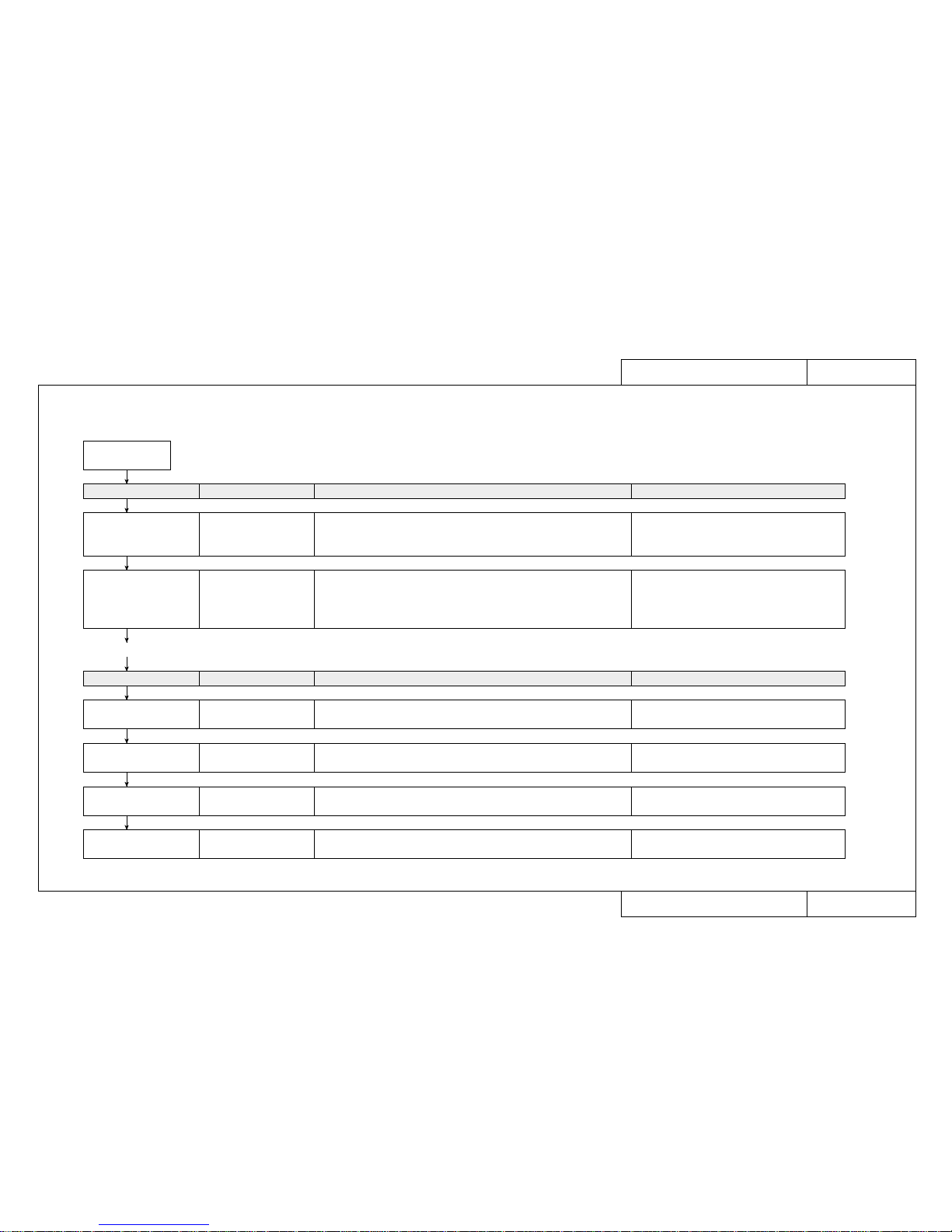
■ Fault maintenance work procedures and how to use the Maintenance Manual
When a user reports an equipment fault, use the following procedure to carry out fault recovery tasks.
A fault occurs
Task Page Details Reference Materials
Check fault circumstances,
select fault details from
Trouble-Shooting Lists
Trouble-Shooting List
TRB❉❉❉❉
Check circumstances by “fax” or “telephone”. Check error
messages, check user usage conditions, retry after changing settings, output
diagnostic pattern, etc. Select fault symptoms produced by user from
the Trouble-Shooting List.
Conduct a consultation by “fax” or “telephone”.
Check possibility of user error or recovery by daily inspection. Check error
messages, check user usage conditions, output diagnostic pattern, output
setup list. Retry after changing settings, etc.
Manual de Operaciones, Conocimiento
báasico, Cuidados diarios, Mantencion periodica/
inspeccion/Limpieza
Task Page Details Reference Materials
Gather the necessary
maintenance parts
Matrix Map
MAP❉❉❉❉
Gather the necessary maintenance parts Maintenance Parts list, Maintenance Tools list,
Exploded views
Conduct a tracing inquiry Fault Tracing Procedures
EXA❉❉❉❉
Conduct an inquiry to trace the cause of the fault Basic knowledge
Replace parts and adjust Replacement and Adjustment
Procedures REP❉❉❉❉
Replace or readjust parts suspected to be faulty.
Carry out adjustments after replacing parts.
Basic knowledge
Final check Separate causes of faults and check operation after faults have been
rectified.
Conduct a primary
consultation with the user
• If you are unable to resolve the fault at this point, take the necessary maintenance parts and make an on-site visit.
Page 14
CON4020
Model Name: Rockhopper-46/62
CON4020
Model Name: Rockhopper-46/62
How to use the Trouble-Shooting Lists (TRB)
How to use the Trouble-Shooting Lists (TRB)
1. How to look up trouble-shooting tables
■ When a user has reported a fault, first select the applicable details from the trouble-shooting lists (TRB) and jump to the specified primary consultation (ENT).
• Faults are broadly classified as those which cause a message to appear in the printer LCD and those which do not.
• For troubles that cause a message to be displayed, select the message as it is.
• Troubles with no message display are classified into the 10 blocks shown below. First select the block then select the appropriate fault details from that block.
2. Definitions of groupings in the case of faults that produce no message display
When Message is Displayed TRB1000
• Printer Status Messages, Data Errors, Command Errors
• CPU System Faults, Mechanical System Faults
When Message is Not Displayed
TRB2000 to TRB2001
•
Trouble with Initialization: Troubles that occur when unpacking immediately after delivery are grouped here.
Check this group for a similar trouble occurring other than immediately after delivery.
Troubles concerning the series of operations up to the enabling of printing are grouped here.
•
Trouble with Printing: This group concerns printing quality problems.
•
Trouble with Media Feed: This group concerns problems with the media path.
•
Trouble with Media Cutting: Cutter section problems are grouped here.
Printing precision problems are grouped here.
•
Problem Involving Noise: Troubles that produce abnormal noise from the driving section.
• Online/Function Problems: Online printing function problems.
Troubles involving driver software, consumable items, peripheral devices are grouped here.
• Other: Troubles concerning the series of operations up to the enabling of printing are grouped here.
Page 15
CON4040
Model Name: Rockhopper-46/62
CON4040
Model Name: Rockhopper-46/62
How to use the Matrix Map (MAP)
How to use the Matrix Map (MAP)
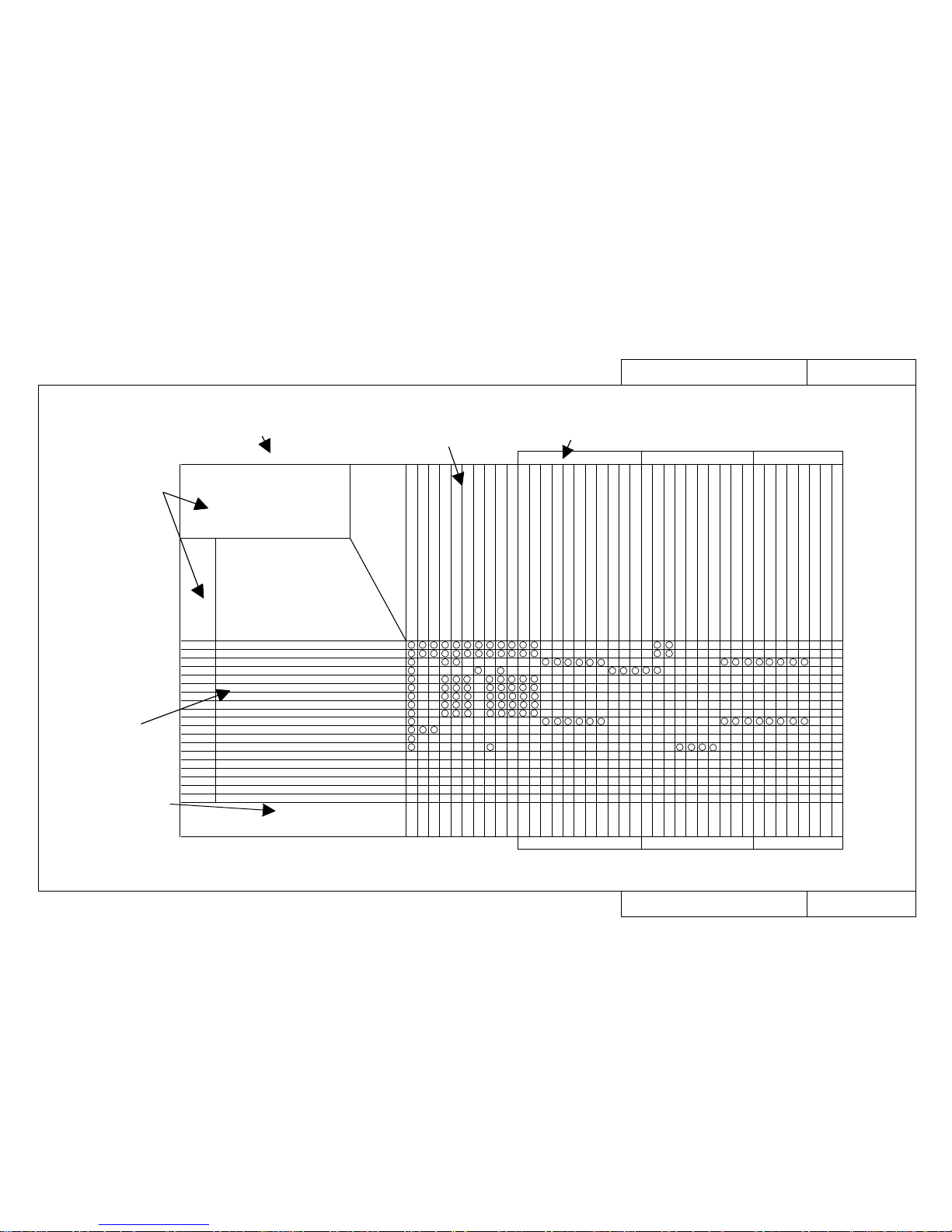
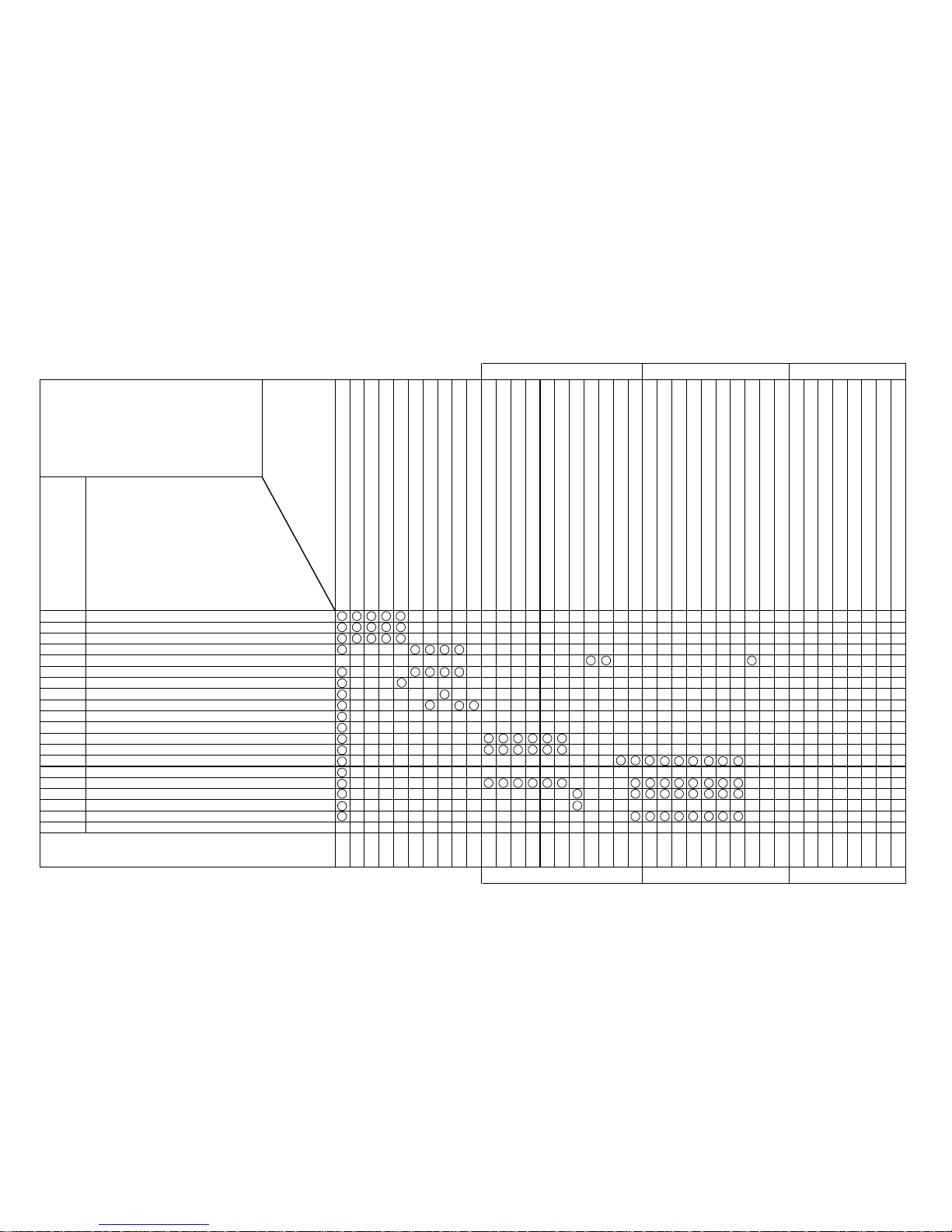
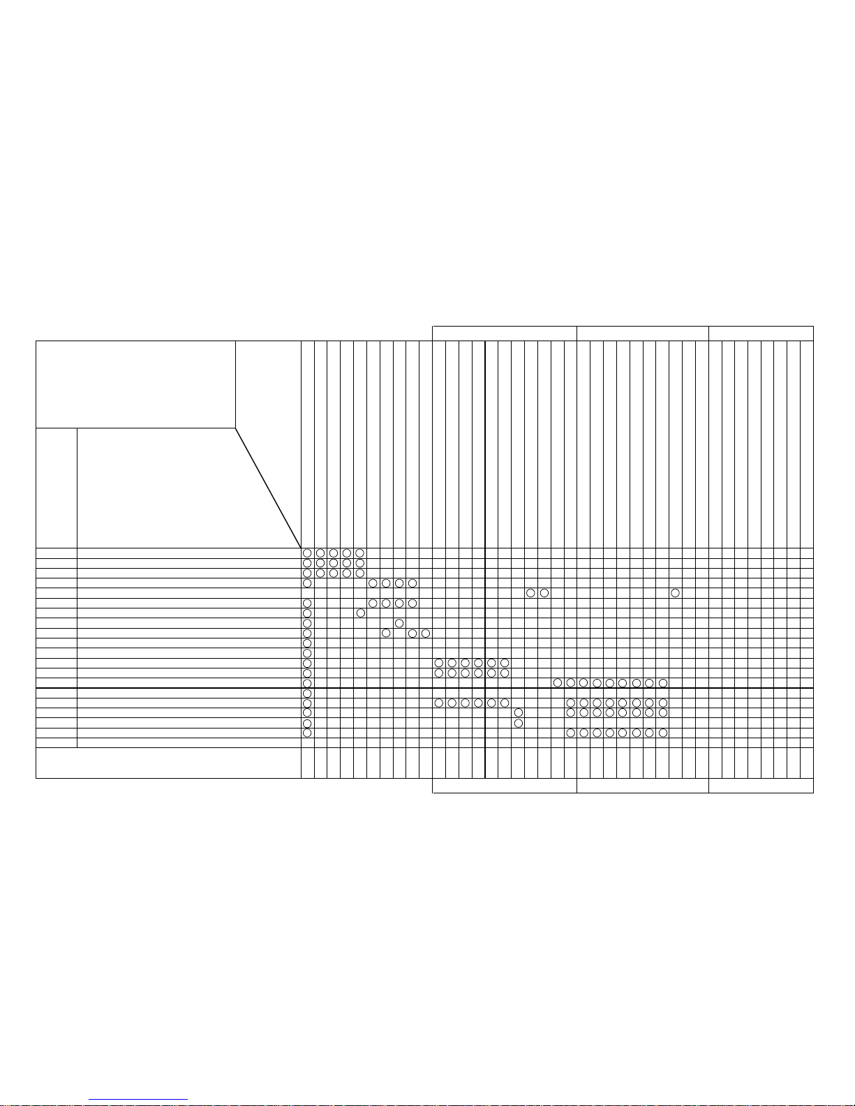
■ When the primary consultation (ENT) has not revealed any anomaly, gather the necessary maintenance parts according to the matrix map (MAP) shown below and visit
the user.
Major classification of fault details
Whether an error message is displayed
Major classification
of fault details and
range of EXA
numbers
Fault
details
Replacement
and adjustment
procedure page
Names and drawing numbers of
required parts
When Message is Not Displayed Trouble with Initialization
Trouble with Initializatio Model Name: 463
MAP2000
When Message is Not Displayed
When Message is Not Displayed
[Trouble with Initialization]
EXA2000 to EXA2070
Problem
- Power supply does not come on
- LCD faulty (no display/erratic display)
- Initial filling of inks failed
- Initial filling is completed but no ink comes out
- After power is switched on, nothing works
- When power is applied, “Initializing” appears and then a reset is executed.
- After mounting media, initial operation fails
- Printer does not work even with the cover closed
- Printer does not stop even with the cover opened
- Ink cartridges are installed but not recognized
- Can not make entries from the operating panel
- Data is received but not plotted
- Media is not suction
Replacement and Adjustment Procedure REP. No.
Name and Diagram Number of
Replacement Part
DF-41586 Main Board Assembly
DF-40097 Panel Board Assembly
DF-41617 Panel Cable
DF-41590 Cover Switch Assembly
DF-41589 Lever Sensor Assembly
DF-41595 Edge Sensor Assembly
DF-41588 Head Board Assembly
DF-41592 XR Cable Assembly (Paper Sensor R)
DF-41600 Y Cable
DF-41619 Switch Cable Assembly
DF-41587 Power Board Assembly
DF-41468 DC Cable Assembly
DF-41593 Detector 1 Assembly
DF-41594 Detector 2 Assembly
DF-40106 Detector Assembly (Black)
DF-40107 Detector Assembly (Y)
DF-40146 Detector Assembly (M)
DF-40147 Detector Assembly (C)
DF-41602 Cap Assembly
DF-41603 Pump Assembly
DF-41604 Maintenance Station Assembly
DF-40690 Print Head Assembly (Colour)
DF-41601 Head Cable
DF-41591 Waste Fluid Box Sensor
DF-40173 Vacuum Fan Assembly
DF-41620 Fan Extension Cable 1 Assembly
DF-41621 Fan Extension Cable 2 Assembly
DF-41622 Fan Extension Cable 3 Assembly
DF-41609 INK ID Sensor 1 Assembly
DF-41610 INK ID Sensor 2 Assembly
DF-41611 INK ID Sensor 3 Assembly
DF-41612 INK ID Sensor 4 Assembly
DF-41613 INK ID Sensor 5 Assembly
DF-41614 INK ID Sensor 6 Assembly
DF-41615 INK ID Sensor Cable
DF-41536 Junction Board Assembly
1140
1160
1170
1110
1100
1410
1420
1200
1360
1130
1150
1130
1350
1350
1350
1350
1350
1350
1240
1260
1270
1390
1390
1120
1080
1080
1080
1080
1340
1340
1340
1340
1340
1340
1470
1470
2000
2000
2010
2020
2030
2030
2030
2030
2030
2040
2050
2060
2070
FaultTracing
Procedure
EXA No.
Page 16
CON4050
Model Name: Rockhopper-46/62
CON4050
Model Name: Rockhopper-46/62
How to use the Fault-Tracing Procedure (EXA)
How to use the Fault-Tracing Procedure (EXA)
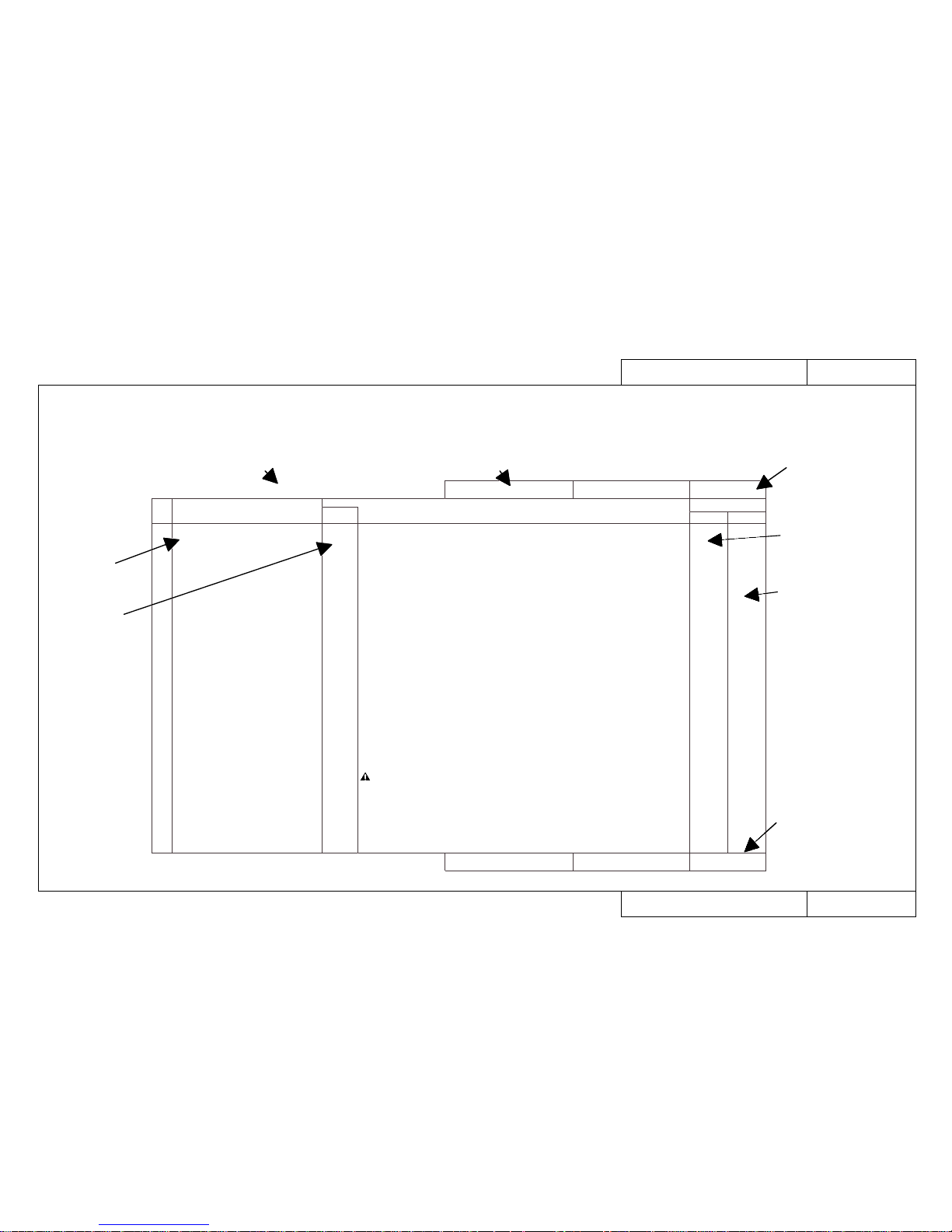
■ Gather the parts specified by the matrix map (MAP), visit the user and carry out the task of recovery in accordance with the fault-tracing procedure (EXA) shown below.
• First, check again on-site that there was no mistake about the primary consultation. (EXA and ENT page numbers are the same)
• Carry out the checking tasks in order, beginning with 1-1, and move to the next task if there is nothing abnormal. If an abnormality is revealed, carry out the task indi-
cated by the arrow [→].
EXA2021
Model Name: Rockhopper-46/62
EXA2021
Model Name: Rockhopper-46/62
Trouble with Initialization
When No Error is Displayed on the Printer's Liquid Crystal Display
1 • Initial filling is completed but no ink
comes out
(Initial filling means to fill the head
with ink to enable it to print.)
1-10
1-11
1-12
1-13
1-14
1-15
1-16
1-17
• Are there any breaks, cuts or air leaks in the ink tubes?
→ Change each ink tube, cleaning each time and checking that ink flows during cleaning.
• Check that connectors J207 (HEAD C1) and J208 (HEAD C2) on the head board assembly, and
head cables on the print head are not inserted obliquely, and they are locked securely.
→ Insert the connectors again.
• Is there a broken lead in head cables?
→ Replace head cables.
• Is the print head assembly damaged?
→ Replace the print head assembly.
• Is the head board assembly damaged?
→ Replace it.
• Check that the Y cable connector is connected securely and not inserted obliquely.
→ Reconnect head board assembly connectors J201 (MAIN1) and J202 (MAIN2) and main board
assembly connectors J111 (HEAD1) and J112 (HEAD 2).
• Is there a broken lead in Y cables?
→ Replace Y cables.
• The main board assembly may be damaged.
→ Replace it.
No. Symptom
Sequence
Items to be Confirmed
When No Error is Displayed on the Printer's Liquid Crystal Display
Trouble with Initialization
1370
1400
1390
1420
1360
1140
REP BAC
GO TO Ref. Pages
CAUTION: Power must be off when connectors are being disconnected or reconnect-
ed, otherwise you may be injured or a board may be damaged.
The main board assembly will certainly be damaged if power is applied
with main board assembly connectors J111 (HEAD) and J112 (HEAD2) and
head board connectors J201 (MAIN1) and J202 (MAIN2) inserted with
oblique FFP.
Whether an error message is displayed
Fault details
Fault-tracing
sequence
Major classification of fault details
Page specified by
matrix map (MAP)
Page specified by
matrix map (MAP)
Replacement and
adjustment procedure
(REP) page reference
Hidden diagnostic
procedure page
reference
Page 17
CON4060
Model Name: Rockhopper-46/62
CON4060
Model Name: Rockhopper-46/62
How to use Replacement and Adjustment Procedure (REP)
How to use Replacement and Adjustment Procedure (REP)
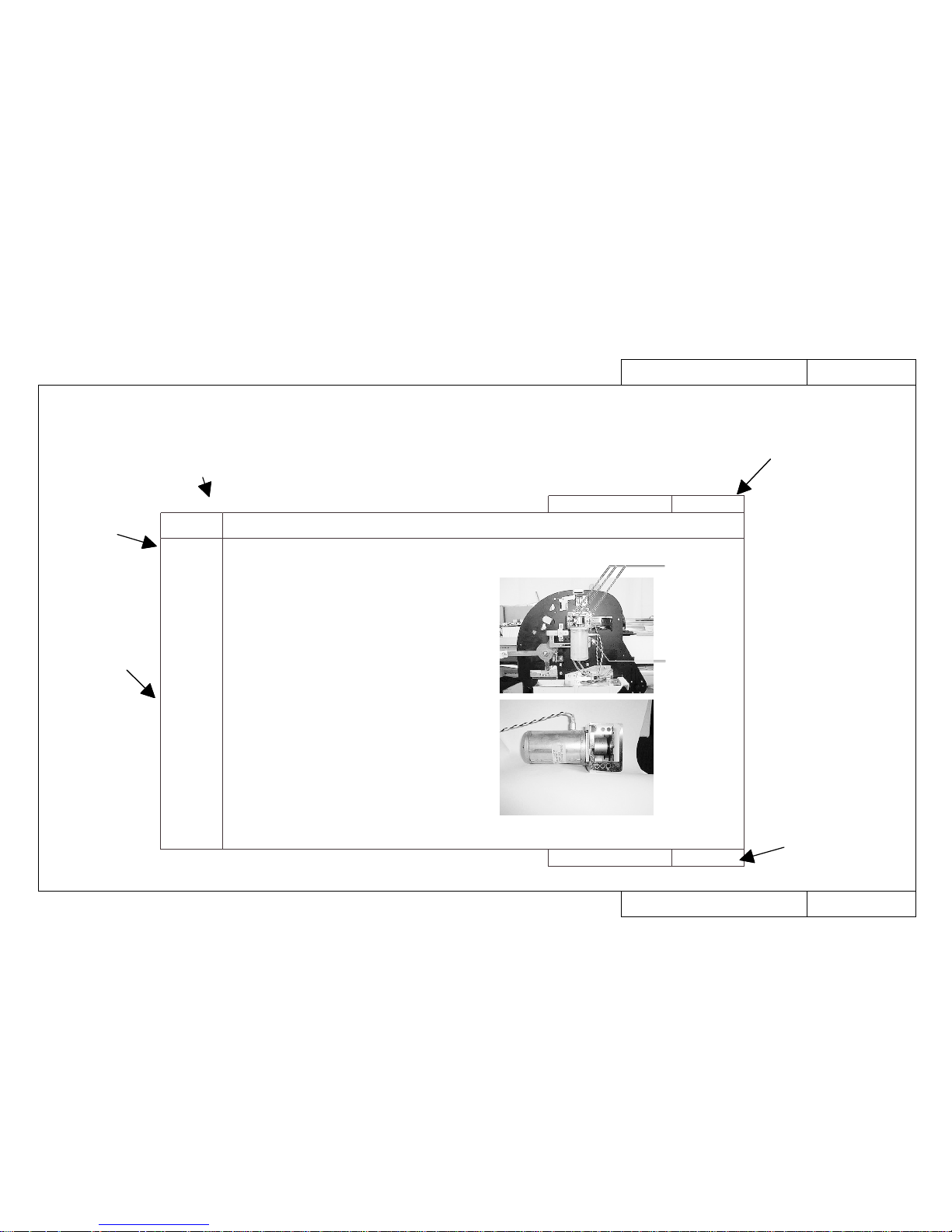
■ If the fault-tracing procedure (EXA) has produced a replacement task, carry out the work of replacement and adjustment in accordance with the replacement and adjustment procedure (REP) shown below.
• If you don’t know how to go about the removal of covers involved in replacing a part, refer to REP1010 to REP1060.
Screws
Y motor cable terminal
Y motor assembly
REP1280
Model Name: Rockhopper-46/62
REP1280
Model Name: Rockhopper-46/62
How to replace the Y Motor Assembly
How to replace the Y Motor Assembly
Item Replacement and Adjustment Procedure
1. Replacement
Procedure
2. Adjustment
and
Examination
Procedure
« REFERENCE » If there is to be no replacement that
includes the Y motor assembly, steps 2, 4
and 5 are not necessary.
Replace the Y Motor Assembly
1. Remove the Left and Right Covers.
2. Remove the Rear Paper Guide.
3. Remove the Steel Belt.
4. Open the Control Box.
5. Disconnect connector J120 (YMOT) from the Main Board
Assembly.
6. Remove the Y Motor Assembly. (3 fastening screws)
7. Assembling is the reverse of the removal procedure.
« REFERENCE » Since the Y Motor Assembly Cable pass-
es below the Cartridge Unit, the work will
be easier if you remove the two Cartridge
Base screws and push it back.
1. Carry out the Steel Belt Tensioning Adjustment.
Replacement and adjustment item
Replacement
procedure
Adjustment
procedure
and items to
be checked
Page specified by
the fault-tracing
procedure (EXA)
Page specified by
the fault-tracing
procedure (EXA)
Page 18
TRB0000
Model Name: Rockhopper-46
TRB0000
Model Name: Rockhopper-46
Rockhopper-463 Trouble-Shooting Lists
Rockhopper-43 Trouble-Shooting Lists
Trouble-Shooting Lists
When Message is Displayed
Printer Status Messages TRB1000
Data Errors TRB1000
Command Errors TRB1000
CPU System Faults TRB1000
Mechanical System Faults TRB1000
When Message is Not Displayed
Trouble with Initialization TRB2000
Trouble with Printing TRB2000
Trouble with Media Feed TRB2000
Trouble with Media Cutting TRB2001
Problem Involving Noise TRB2001
Online/Function Problems TRB2001
Others TRB2001
Heater System TRB2001
How to Use LEDs to Check CPU System TRB1001
and Mechanical System Faults
Heaters System Faults TRB1000
Page 19
TRB0000-3
Model Name: Rockhopper-62
TRB0000-3
Model Name: Rockhopper-62
Rockhopper-62 Trouble-Shooting Lists
Rockhopper-62 Trouble-Shooting Lists
Trouble-Shooting Lists
When Message is Displayed
Printer Status Messages TRB1000
Data Errors TRB1000
Command Errors TRB1000
CPU System Faults TRB1000
Mechanical System Faults TRB1000
When Message is Not Displayed
Trouble with Initialization TRB2000
Trouble with Printing TRB2000
Trouble with Media Feed TRB2000
Trouble with Media Cutting TRB2001
Problem Involving Noise TRB2001
Online/Function Problems TRB2001
Others TRB2001
Heater System TRB2001
How to Use LEDs to Check CPU System TRB1001
and Mechanical System Faults
Heaters System Faults TRB1000
Page 20
When Message is Displayed
When Message is Displayed
TRB1000
Model Name: Rockhopper-46/62
TRB1000
Model Name: Rockhopper-46/62
Trouble-Shooting 1/3 (List of Faults)
Trouble-Shooting 1/3 (List of Faults)
Cases where an error message is displayed on the liquid crystal display of the main printer unit
GO TO EXA No.Minor Faults CPU System/Mechanical System Faults GO TO EXA No.
Printer Status Messages
CPU System Faults
• Cover Open
• Lever Up
• Cover and Lever
• Undefined Media
• Media Skew Error
• [User 1] Media End
• Remove Media
• Roll Media End
• Media Cut Error
• Not enough memory SIMM 12 MB
• Insert Special Cartridge
• [ ∗ ] Ink Low
• [ ∗ ] No Ink
• [ ∗ ] No Cartridge
• Capping position not specified
• Not Filled
• No Waste Fluid Box
• Wrong Ink Type
EXA1000
EXA1000
EXA1000
EXA1010
EXA1020
EXA1030
EXA1040
EXA1050
EXA1060
EXA1070
EXA1080
EXA1090
EXA1090
EXA1100
EXA1110
EXA1120
EXA1130
EXA1150
• E001 Error DRAM (Standard DRAM error)
• E002 Error Opt.DRAM (Optional DRAM error)
•E016CPUErr[00] (Interrupt exception error)
•E016CPUErr[02] (Command boundary exception error)
•E016CPUErr[03] (Data boundary exception error)
•E016CPUErr[04] (Address error exception)
(Load or command fetch)
•E016CPUErr[05] (Address error exception) (Store)
•E016CPUErr[06] (Bus error exception) (Command fetch)
•E016CPUErr[07] (Bus error exception) (Data load)
•E016CPUErr[08] (System call exception error)
•E016CPUErr[09] (Break point exception error)
•E016CPUErr[10] (Reserved command exception error)
•E016CPUErr[11] (Unable to use coprocessor exception error)
•E016CPUErr[12] (Operation overflow exception error)
•E016CPUErr[13] (Trap exception error)
•E016CPUErr[15] (Floating point exception error)
•E016CPUErr[22] (Watch exception error)
•E016CPUErr[32] (Watchdog timeout exception error)
•E016CPUErr[33] (Abort error)
• Error E237 Transfer memory (Transfer memory error/Transfer memory
access error)
• Error E129 NVRAM
EXA1500
EXA1500
EXA1510
EXA1510
EXA1510
EXA1510
EXA1510
EXA1510
EXA1510
EXA1510
EXA1510
EXA1520
EXA1520
EXA1520
EXA1520
EXA1520
EXA1520
EXA1520
EXA1520
EXA1520
EXA1530
Mechanical System Faults
• E065 Error X Motor
• E069 Error X Encoder
• E071 Error X Timeout
• E073 Error X Overcurrent
• E066 Error Y Motor
• E070 Error Y Encoder
• E072 Error Y Timeout
• E074 Error Y Overcurrent
• E075 Error Sensor Fault
EXA1700
EXA1700
EXA1700
EXA1700
EXA1710
EXA1710
EXA1710
EXA1710
EXA1720
Data Errors
• Network Detection Error
• Network Initialization Error
EXA1230
EXA1230
Command Errors
• MH01 Error (Undefined Command)
• MH02 Error (Parameter Error)
• MH03 Error (Numerical Error)
• MH04 Error (Undefined Character Set)
• MH07 Error (Buffer Overflow)
EXA1250
EXA1250
EXA1250
EXA1250
EXA1250
Heater System Faults EXA1800
Page 21
TRB1001
Model Name: Rockhopper-46/62
TRB1001
Model Name: Rockhopper-46/62
How to Use LEDs to Check CPU System and Mechanical System Faults
How to Use LEDs to Check CPU System and Mechanical System Faults
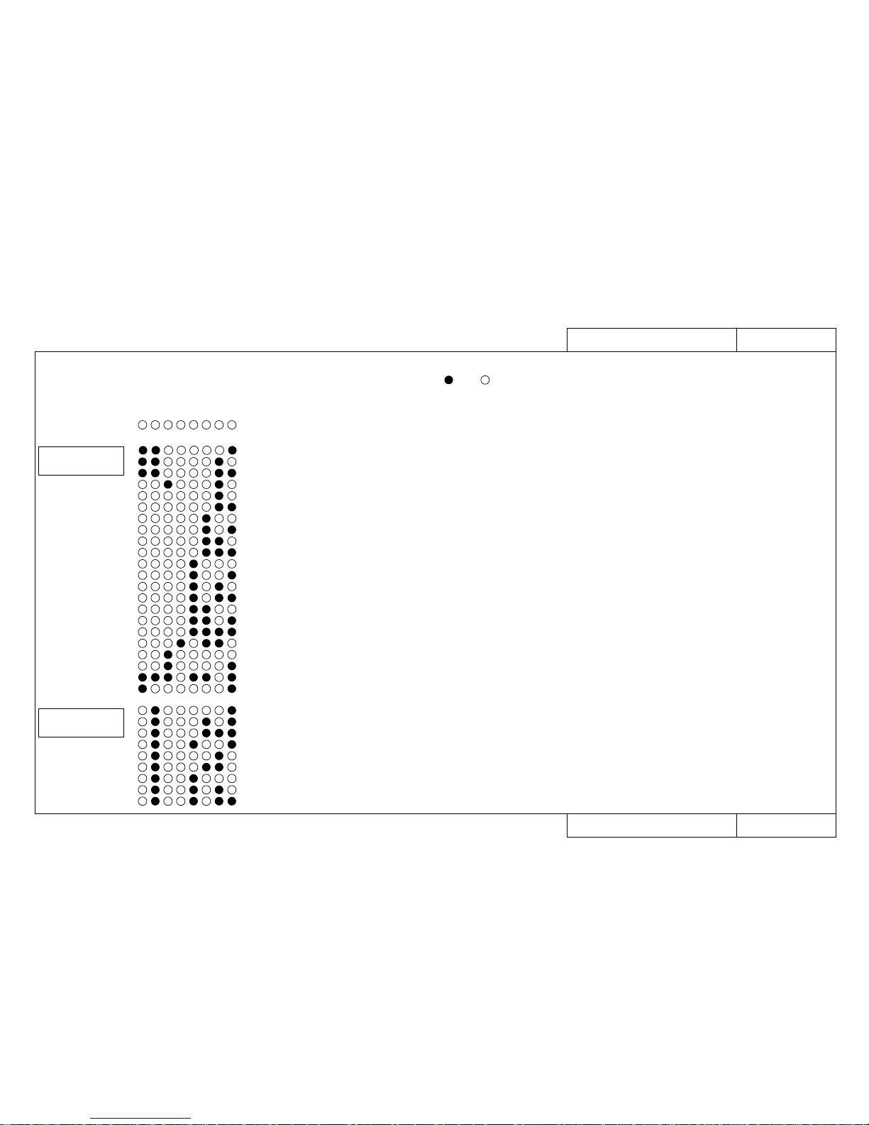
• When the printer stops working and nothing appears on the liquid crystal display (LCD),
a fault has probably occurred in the CPU system or the mechanical system.
In that case, open the control box and check the error by the LEDs on the main board assembly. is on, is off.
LED display
12345678
• E001 Error DRAM
Fallas Sistema CPU
Details of Error
• E002 Error Opt.DRAM
• E002 Error Opt.DRAM
• E016CPUErr[00]
• E016CPUErr[02]
• E016CPUErr[03]
• E016CPUErr[04]
• E016CPUErr[05]
• E016CPUErr[06]
• E016CPUErr[07]
• E016CPUErr[08]
• E016CPUErr[09]
• E016CPUErr[10]
• E016CPUErr[11]
• E016CPUErr[12]
• E016CPUErr[13]
• E016CPUErr[15]
• E016CPUErr[22]
• E016CPUErr[32]
• E016CPUErr[33]
• E237 Error Transfer memory
• E129 Error NVRAM
(Standard DRAM error)
(Optional DRAM 1 error)
(Optional DRAM 2 error)
(Interrupt exception error)
(Command boundary exception error)
(Data boundary exception error)
(Address error exception) (Load or command fetch)
(Address error exception) (Store)
(Bus error exception) (Command fetch)
(Bus error exception) (Data load)
(System call exception error)
(Break point exception error)
(Reserved command exception error)
(Unable to use coprocessor exception error)
(Operation overflow exception error)
(Trap exception error)
(Floating point exception error)
(Watch exception error)
(Watchdog timeout exception error)
(Abort error)
(Transfer memory error/Transfer memory access error)
EXA1500
Fault-Tracing Procedure
EXA page
EXA1500
EXA1500
EXA1510
EXA1510
EXA1510
EXA1510
EXA1510
EXA1510
EXA1510
EXA1510
EXA1510
EXA1520
EXA1520
EXA1520
EXA1520
EXA1520
EXA1520
EXA1520
EXA1520
EXA1520
EXA1530
• E065 Error X Motor
• E066 Error Y Motor
• E069 Error X Encoder
• E070 Error Y Encoder
• E071 Error X Timeout
• E072 Error Y Timeout
• E073 Error X Overcurrent
• E074 Error Y Overcurrent
• E075 Error Sensor Fault
EXA1700
EXA1700
EXA1700
EXA1700
EXA1710
EXA1710
EXA1710
EXA1710
EXA1720
FALLAS SISTEMA
MECANICO
Page 22
TRB2000
Model Name: Rockhopper-46/62
TRB2000
Model Name: Rockhopper-46/62
Trouble-Shooting 2/3 (List of Faults)
Trouble-Shooting 2/3 (List of Faults)
When Message is Not Displayed
When Message is Not Displayed
GO TO
EXA No.
Cases where no error message is displayed
on the liquid crystal display of the main printer unit
GO TO
EXA No.
Cases where no error message is displayed
on the liquid crystal display of the main printer unit
Trouble with Initialization
Trouble with Printing
• No power
• Faulty liquid crystal display (no display/unstable display)
• Initial filling of inks failed
• Initial filling is completed but no ink comes out
• After power is switched on, nothing works
•
When power is applied, “Initializing” appears and then a reset is executed.
• Media is mounted but the initialization operation is not done
• Printer does not work even with the cover closed
• Printer does not stop even with the cover opened
• Ink cartridges are installed but not recognized
• No se puede entrar al Panel de Operaciones
• Data is received but not printed
• Media is not suction
EXA2000
EXA2000
EXA2010
EXA2020
EXA2030
EXA2030
EXA2030
EXA2030
EXA2030
EXA2040
EXA2050
EXA2060
EXA2070
EXA3000
EXA3000
EXA3000
EXA3000
EXA3000
EXA3010
EXA3010
• No imprime en forma continua
• There is an extra feed after printing is finished
• Dots are missing from the printing
• Cleaning does not cure blockage
• No imprime nada
• No imprime un color especifico
• La superficie entera se imprime en negro
• Printing becomes shaded
• The image contains blurs
• Transverse lines appear to be split
• AParecen lineas blancas y negras en la impresion
• Orillas de la impresion aparecen borrosas
• Many satellites (unwanted dots)
• The printing has whiskers
• Printed lines appear blurred (printing is dirty)
• Mixed colour lines do not overlap
• Black and colour positions are offset
•
Inaccurate line length in the direction of head movement (Main scanning direction)
• Inaccurate straight line in the direction of head movement (straightness)
•
Inaccurate line distance in the direction of media feed (Subsidiary scanning distance)
• Inaccurate straight line in the direction of media feed (joining precision Y)
• Bad right angle precision
EXA4000
EXA4010
EXA4020
EXA4020
EXA4030
EXA4030
EXA4040
EXA4050
EXA4050
EXA4050
EXA4050
EXA4060
EXA4070
EXA4070
EXA4070
EXA4080
EXA4080
EXA4090
EXA4100
EXA4110
EXA4120
EXA4130
Trouble with Media Feed
• The media comes off when it is initialized or during printing
• The media is skewed or meanders when it is initialized or during printing
• The media becomes wrinkled when it is initialized or during printing
• The media jams when it is initialized or during printing
• The media tears when it is initialized or during printing
• The media size is different after media mounting and initialization
• Tracing paper and thin media cannot be detected
Page 23
TRB2001
Model Name: Rockhopper-46/62
TRB2001
Model Name: Rockhopper-46/62
Trouble-Shooting 3/3 (List of Faults)
Trouble-Shooting 3/3 (List of Faults)
When Message is Not Displayed
When Message is Not Displayed
GO TO
EXA No.
Cases where no error message is displayed
on the liquid crystal display of the main printer unit
GO TO
EXA No.
Cases where no error message is displayed
on the liquid crystal display of the main printer unit
Problem Involving Noise
Online/Function ProblemsOthers
• Abnormal noise when media is sucked down
• Abnormal noise when standing by ready to print
• Abnormal noise when head is moving left and right
• Abnormal noise when media is fed
• Abnormal noise when cutting
EXA5000
EXA5010
EXA5020
EXA5030
EXA5040
EXA6000
EXA6010
EXA6020
EXA6020
EXA6030
EXA6040
EXA6050
EXA6050
EXA7000
EXA7000
EXA7020
EXA7020
EXA7020
EXA7020
EXA7030
EXA7040
EXA7050
EXA7060
• The printer hangs up
• Power shutdown during printing
• The ink cartridges will not go in
• Ink has overflowed from the waste fluid box
• Ink overflows from flushing box
• Ink is split around the X-rail
• Cannot connect normally with Centronics
• Cannot connect normally with Network
• The scale function does not work correctly
• The rotate function does not work correctly
• The mirror function does not work correctly
• Other functions are not working correctly
• Printing position is offset
• Some data are not printed (omitted)
• Text and printing data are garbled (extra lines appear)
• There is an extra feed after printing is finished
EXA8000
EXA8010
EXA8020
EXA8050
EXA8050
EXA8050
Trouble with Media Cutting
• Does not cut normally
• Cutting occurs during printing
• The cutting operation is normal but the media is not cut
• The cutting is bad and the media jams
• The cutting operation is normal but the media does not fall out
• Inaccurate media cutting
• Cutting is delayed for some time after printing has ended
• White paper is cut (Blank print)
Sistema Calefactores EXA9000
Page 24
MAP0000
MAP0000
Rockhopper-463 Matrix Map
Rockhopper-463 Matrix Map
Matrix Map
When Message is Displayed
Printer Status Messages MAP1000
Data Errors MAP1200
Command Errors MAP1200
CPU System Faults MAP1500
Mechanical System Faults MAP1700
When Message is Not Displayed
Trouble with Initialization MAP2000
Trouble with Printing MAP4000
Trouble with Media Feed MAP3000
Trouble with Media Cutting MAP6000
Problem Involving Noise MAP5000
Online/Function Problems MAP7000
Other MAP8000
Model Name: Rockhopper-46
Model Name: Rockhopper-46
Heater System MAP9000
Heaters Fault MAP1800
Page 25
MAP0000-3
MAP0000-3
Rockhopper-62 Matrix Map
Rockhopper-62 Matrix Map
Matrix Map
When Message is Displayed
Printer Status Messages MAP1000-3
Data Errors MAP1200
Command Errors MAP1200
CPU System Faults MAP1500
Mechanical System Faults MAP1700-2
When Message is Not Displayed
Trouble with Initialization MAP2000-2
Trouble with Printing MAP4000-2, 4001-3
Trouble with Media Feed MAP3000-3
Trouble with Media Cutting MAP6000-2
Problem Involving Noise MAP5000-3
Online/Function Problems MAP7000-2
Other MAP8000-2
Model Name: Rockhopper-62
Model Name: Rockhopper-62
Heater System MAP9000-2
Heaters Fault MAP1800-2
Page 26
When Message is Displayed Printer Status Messages Model Name: Rockhopper463 MAP1000
Printer Status Messages Model Name: Rockhopper463 MAP1000
1000
1000
1000
1010
1020
1030
1040
1050
1060
1070
1080
1090
1090
1100
1110
1120
1130
1150
1140
1160
1110
1170
1100
1410
1420
1200
1360
1380
1350
1350
1350
1350
1350
1350
1120
1220
1220
1330
1340
1340
1340
1340
1340
1340
1470
1470
1690
When Message is Displayed
When Message is Displayed
[Printer Status Display]
EXA1000 to EXA1150
Problem
- Cover open
- Lever up
- Cover & Lever
- Undefined Media
- Media Skew Error
- [User 1] Media End
- Remove Media
- Roll Media End
- Media Cut Error
- Not enough memory SIMM12MB
- Insert Special Cartridge
- [✼✼] Ink Low
- [✼✼] No Ink
- [✼✼] No Cartridge
- Capping position not specified
- Not Filled
- No Waste Fluid Box
- Wrong Ink Type
Replacement and Adjustment Procedure REP. No.
Name and Diagram Number of
Replacement Part
DF-41586 Main Board Assembly
DF-40097 Panel Board Assembly
DF-41590 Cover Switch Assembly
DF-41617 Panel Cable
DF-41589 Lever Sensor Assembly
DF-41595 Edge Sensor Assembly
DF-41588 Head Board Assembly
DF-41592 XR Cable Assembly (Paper Sensor R)
DF-41600 Y Cable
DF-40113 Cutter Solenoid Assembly
DF-41593 Detector1 Assembly
DF-41594 Detector2 Assembly
DF-40106 Detector Assembly (Black)
DF-40107 Detector Assembly (Y)
DF-40146 Detector Assembly (M)
DF-40147 Detector Assembly (C)
DF-41591 Waste Fluid Box Sensor Assembly
DF-41529 Pressure Assembly
DF-41530 Pressure Roller
DF-40127 Cartridge Frame Assembly
DF-41609 Ink ID Sensor1 Assembly
DF-41610 Ink ID Sensor2 Assembly
DF-41611 Ink ID Sensor3 Assembly
DF-41612 Ink ID Sensor4 Assembly
DF-41613 Ink ID Sensor5 Assembly
DF-41614 Ink ID Sensor6 Assembly
DF-41615 Ink ID Cable
DF-41536 Junction Board Assembly
DF-41840 Grid Roller Assembly
FaultTracing
Procedure
EXA No.
Page 27
When Message is Displayed Printer Status Messages Model Name: Rockhopper62 MAP1000-3
Printer Status Messages Model Name: Rockhopper62 MAP1000-3
1000
1000
1000
1010
1020-2
1030
1040
1050
1060
1070
1080
1090
1090
1100
1110
1120
1130
1150
1140
1160
1110
1170
1100
1410
1420
1200
1360-2
1380
1350
1350
1350
1350
1350
1350
1120
1220
1220
1330
1340
1340
1340
1340
1340
1340
1470
1470
1690
1690
When Message is Displayed
When Message is Displayed
[Printer Status Display]
EXA1000 to EXA1150
Problem
- Cover open
- Lever up
- Cover & Lever
- Undefined Media
- Media Skew Error
- [User 1] Media End
- Remove Media
- Roll Media End
- Media Cut Error
- Not enough memory SIMM12MB
- Insert Special Cartridge
- [✼✼] Ink Low
- [✼✼] No Ink
- [✼✼] No Cartridge
- Capping position not specified
- Not Filled
- No Waste Fluid Box
- Wrong Ink Type
Replacement and Adjustment Procedure REP. No.
Name and Diagram Number of
Replacement Part
DF-41586 Main Board Assembly
DF-40097 Panel Board Assembly
DF-41590 Cover Switch Assembly
DF-41617 Panel Cable
DF-41589 Lever Sensor Assembly
DF-41595 Edge Sensor Assembly
DF-41588 Head Board Assembly
DF-41592 XR Cable Assembly (Paper Sensor R)
DF-41600 Y Cable
DF-40113 Cutter Solenoid Assembly
DF-41593 Detector1 Assembly
DF-41594 Detector2 Assembly
DF-40106 Detector Assembly (Black)
DF-40107 Detector Assembly (Y)
DF-40146 Detector Assembly (M)
DF-40147 Detector Assembly (C)
DF-41591 Waste Fluid Box Sensor Assembly
DF-41529 Pressure Assembly
DF-41530 Pressure Roller
DF-40127 Cartridge Frame Assembly
DF-41609 Ink ID Sensor1 Assembly
DF-41610 Ink ID Sensor2 Assembly
DF-41611 Ink ID Sensor3 Assembly
DF-41612 Ink ID Sensor4 Assembly
DF-41613 Ink ID Sensor5 Assembly
DF-41614 Ink ID Sensor6 Assembly
DF-41615 Ink ID Cable
DF-41536 Junction Board Assembly
DF-41840 Grid Roller Assembly
FaultTracing
Procedure
EXA No.
Page 28
When Message is Displayed Data Errors, Command Errors MAP1200
Data Errors, Command Errors Model Name: Rockhopper-46/62
Model Name: Rockhopper-46/62
MAP1200
1230
1230
1250
1250
1250
1250
1250
1140
When Message is Displayed
When Message is Displayed
[Data Errors, Command Errors]
EXA1230 to EXA1250
Problem
- Network Detection Error
- Network Initialization Error
- MH01 Error (Undefined Command)
- MH02 Error (Parameter Error)
- MH03 Error (Numerical Error)
- MH04 Error (Undefined Character Set)
- MH07 Error (Buffer Overflow)
Replacement and Adjustment Procedure REP. No.
Name and Diagram Number of
Replacement Part
DF-41586 Main Board Assembly
FaultTracing
Procedure
EXA No.
Page 29
When Message is Displayed CPU System Faults MAP1500
CPU System Faults Model Name: Rockhopper-46/62
Model Name: Rockhopper-46/62
MAP1500
1500
1500
1510
1510
1510
1510
1510
1510
1510
1510
1510
1520
1520
1520
1520
1520
1520
1520
1520
1520
1530
1140
When Message is Displayed
When Message is Displayed
[CPU System Faults]
EXA1500 to EXA1530
Problem
- E001 Error DRAM (Standard DRAM error)
- E002 Error Opt.DRAM (Optional DRAM error)
- E016 CPUErr[00] (Interrupt exception error)
- E016 CPUErr[02] (Command boundary exception error)
- E016 CPUErr[03] (Data boundary exception error)
- E016 CPUErr[04] (Address error exception load)
- E016 CPUErr[05] (Address error exception store)
- E016 CPUErr[06] (Bus error exception check)
- E016 CPUErr[07] (Bus error exception load)
- E016 CPUErr[08] (System call exception)
- E016 CPUErr[09] (Break point exception)
- E016 CPUErr[10] (Reserved command exception)
- E016 CPUErr[11] (Processor usage denial exception)
- E016 CPUErr[12] (Operation overflow exception)
- E016 CPUErr[13] (Trap exception)
- E016 CPUErr[15] (Floating point exception)
- E016 CPUErr[22] (Watch exception)
- E016 CPUErr[32] (Watchdog timeout error)
- E016 CPUErr[33] (Abort error)
- E237 Error Transfer memory (Transfer memory error/access error)
- Error E129 NVRAM (Backup memory error)
Replacement and Adjustment Procedure REP. No.
Name and Diagram Number of
Replacement Part
DF-41586 Main Board Assembly
FaultTracing
Procedure
EXA No.
Page 30
When Message is Displayed Mechanical System Faults Model N.:Rockhopper-463 MAP1700
Mechanical System Faults Model N.: Rockhopper-463 MAP1700
1140
1070
1280
1290
1450
1150
1080
1080
1080
1080
When Message is Displayed
When Message is Displayed
[Mechanical System Faults]
EXA1700 to EXA1720
Problem
- Error E065 X Motor
- Error E069 X Encoder
- Error E071 X Timeout
- Error E073 X Overcurrent
- Error E066 Y Motor
- Error E070 Y Encoder
- Error E072 Y Timeout
- Error E074 Y Overcurrent
- Error E075 Sensor Abnormal
Replacement and Adjustment Procedure REP. No.
Name and Diagram Number of
Replacement Part
DF-41586 Main Board Assembly
DF-41597 X Motor Assembly
DF-41598 CR Motor Assembly (Y Motor)
DF-41607 T Fence
DF-40109 Origin Sensor Assembly
DF-41587 Power Board Assembly
DF-40173 Vacuum Fan Assembly
DF-41620 Fan Extension Cable 1 Assembly
DF-41621 Fan Extension Cable 2 Assembly
DF-41622 Fan Extension Cable 3 Assembly
1700
1700
1700
1700
1710
1710
1710
1710
1720
FaultTracing
Procedure
EXA No.
Page 31

When Message is Displayed Mechanical System Faults Model Name: Rockhopper 62 MAP1700-2
Mechanical System Faults Model Name: Rockhopper 62 MAP1700-2
1140
1070
1280
1290
1450
1150
1080-2
1080-2
1080-2
1080-2
1080-2
When Message is Displayed
When Message is Displayed
[Mechanical System Faults]
EXA1700 to EXA1720
Problem
- Error E065 X Motor
- Error E069 X Encoder
- Error E071 X Timeout
- Error E073 X Overcurrent
- Error E066 Y Motor
- Error E070 Y Encoder
- Error E072 Y Timeout
- Error E074 Y Overcurrent
- Error E075 Sensor Abnormal
Replacement and Adjustment Procedure REP. No.
Name and Diagram Number of
Replacement Part
DF-41586 Main Board Assembly
DF-41597 X Motor Assembly
DF-41598 CR Motor Assembly (Y Motor)
DF-41607 T Fence
DF-40109 Origin Sensor Assembly
DF-41587 Power Board Assembly
DF-40173 Vacuum Fan Assembly
DF-41620 Fan Extension Cable 1 Assembly
DF-41621 Fan Extension Cable 2 Assembly
DF-41622 Fan Extension Cable 3 Assembly
DF-41993 Fan Extension Cable 4 Assembly
1700
1700
1700
1700
1710
1710
1710
1710
1720
FaultTracing
Procedure
EXA No.
Page 32

When Message is Displayed d Heater System Faultsr Model N:Rockhopper46 3 MAP1800
Heater System Faultsr Model N:Rockhopper46 3 MAP1800
When Message is Displayed
When Message is Displayed
[Heater system]
EXA1800
Problem
- Err : F.R.T. Sensor
Replacement and Adjustment Procedure REP. No.
Name and Diagram Number of
Replacement Part
Front Right Heater Sensor
Front Left Heater Sensor
Rear Right Heater Sensor
Rear Left Heater Sensor
1040
104
0
1040
1040
1800
FaultTracing
Procedure
EXA No.
- Err : F.L.T. Sensor
1800
- Err : R.L.T. Sensor
1800
- Err : R.R.T. Sensor
1800
- Err : FRFLT Sensor
1800
- Err : FRRLT Sensor
1800
- Err : FRRRT Sensor
1800
- Err : FLRLT Sensor
1800
- Err : FLRRT Sensor
1800
- Err : RRRLT Sensor
1800
- Err : 2FRLT Sensor
1800
- Err : 2FRRT Sensor
1800
- Err : FR2RT Sensor
1800
- Err : FL2RT Sensor
1800
- Err : All T. Sensor
1800
- Err : Heater Stop
1800
Heater System
1040
Page 33

When Message is Displayed d Heater System Faultsr Model N:Rockhopper62 3 MAP1800-2
Heater System Faultsr Model N:Rockhopper62 3 MAP1800-2
When Message is Displayed
When Message is Displayed
[Heater system]
EXA1800
Problem
- Err : F.R.T. Sensor
Replacement and Adjustment Procedure REP. No.
Name and Diagram Number of
Replacement Part
Front Right Heater Sensor
Front Left Heater Sensor
Rear Right Heater Sensor
Rear Left Heater Sensor
1040 -2
104
0 -2
1040 -2
1040 -2
1800
FaultTracing
Procedure
EXA No.
- Err : F.L.T. Sensor
1800
- Err : R.L.T. Sensor
1800
- Err : R.R.T. Sensor
1800
- Err : FRFLT Sensor
1800
- Err : FRRLT Sensor
1800
- Err : FRRRT Sensor
1800
- Err : FLRLT Sensor
1800
- Err : FLRRT Sensor
1800
- Err : RRRLT Sensor
1800
- Err : 2FRLT Sensor
1800
- Err : 2FRRT Sensor
1800
- Err : FR2RT Sensor
1800
- Err : FL2RT Sensor
1800
- Err : All T. Sensor
1800
- Err : Heater Stop
1800
Heater System
1040 -2
Page 34

When Message is Not Displayed Trouble with Initialization Model N. :Rockhopper463 MAP2000
Trouble with Initialization Model N. : Rockhopper463 MAP2000
When Message is Not Displayed
When Message is Not Displayed
[Trouble with Initialization]
EXA2000 to EXA2070
Problem
- Power supply does not come on
- LCD faulty (no display/erratic display)
- Initial filling of inks failed
- Initial filling is completed but no ink comes out
- After power is switched on, nothing works
- When power is applied, “Initializing” appears and then a reset is executed.
- After mounting media, initial operation fails
- Printer does not work even with the cover closed
- Printer does not stop even with the cover opened
- Ink cartridges are installed but not recognized
- Can not make entries from the operating panel
- Data is received but not plotted
- Media is not suction
Replacement and Adjustment Procedure REP. No.
Name and Diagram Number of
Replacement Part
DF-41586 Main Board Assembly
DF-40097 Panel Board Assembly
DF-41617 Panel Cable
DF-41590 Cover Switch Assembly
DF-41589 Lever Sensor Assembly
DF-41595 Edge Sensor Assembly
DF-41588 Head Board Assembly
DF-41592 XR Cable Assembly (Paper Sensor R)
DF-41600 Y Cable
DF-41619 Switch Cable Assembly
DF-41587 Power Board Assembly
DF-41468 DC Cable Assembly
DF-41593 Detector 1 Assembly
DF-41594 Detector 2 Assembly
DF-40106 Detector Assembly (Black)
DF-40107 Detector Assembly (Y)
DF-40146 Detector Assembly (M)
DF-40147 Detector Assembly (C)
DF-41602 Cap Assembly
DF-41603 Pump Assembly
DF-41604 Maintenance Station Assembly
DF-40690 Print Head Assembly (Colour)
DF-41601 Head Cable
DF-41591 Waste Fluid Bottle Sensor
DF-40173 Vacuum Fan Assembly
DF-41620 Fan Extension Cable 1 Assembly
DF-41621 Fan Extension Cable 2 Assembly
DF-41622 Fan Extension Cable 3 Assembly
DF-41609 INK ID Sensor 1 Assembly
DF-41610 INK ID Sensor 2 Assembly
DF-41611 INK ID Sensor 3 Assembly
DF-41612 INK ID Sensor 4 Assembly
DF-41613 INK ID Sensor 5 Assembly
DF-41614 INK ID Sensor 6 Assembly
DF-41615 INK ID Sensor Cable
DF-41536 Junction Board Assembly
1140
1160
1170
1110
1100
1410
1420
1200
1360
1130
1150
1130
1350
1350
1350
1350
1350
1350
1240
1260
1270
1390
1390
1120
1080
1080
1080
1080
1340
1340
1340
1340
1340
1340
1470
1470
2000
2000
2010
2020
2030
2030
2030
2030
2030
2040
2050
2060
2070
FaultTracing
Procedure
EXA No.
Page 35

When Message is Not Displayed Trouble with Initialization Model Name: Rockhopper 62 MAP2000-2
Trouble with Initialization Model Name: Rockhopper 62 MAP2000-2
When Message is Not Displayed
When Message is Not Displayed
[Trouble with Initialization]
EXA2000 to EXA2070-2
Problem
- Power supply does not come on
- LCD faulty (no display/erratic display)
- Initial filling of inks failed
- Initial filling is completed but no ink comes out
- After power is switched on, nothing works
- When power is applied, “Initializing” appears and then a reset is executed.
- After mounting media, initial operation fails
- Printer does not work even with the cover closed
- Printer does not stop even with the cover opened
- Ink cartridges are installed but not recognized
- Can not make entries from the operating panel
- Data is received but not plotted
- Media is not suction
Replacement and Adjustment Procedure REP. No.
Name and Diagram Number of
Replacement Part
DF-41586 Main Board Assembly
DF-40097 Panel Board Assembly
DF-41617 Panel Cable
DF-41590 Cover Switch Assembly
DF-41589 Lever Sensor Assembly
DF-41595 Edge Sensor Assembly
DF-41588 Head Board Assembly
DF-41592 XR Cable Assembly (Paper Sensor R)
DF-41600 Y Cable
DF-41619 Switch Cable Assembly
DF-41587 Power Board Assembly
DF-41468 DC Cable Assembly
DF-41593 Detector 1 Assembly
DF-41594 Detector 2 Assembly
DF-40106 Detector Assembly (Black)
DF-40107 Detector Assembly (Y)
DF-40146 Detector Assembly (M)
DF-40147 Detector Assembly (C)
DF-41602 Cap Assembly
DF-41603 Pump Assembly
DF-41604 Maintenance Station Assembly
DF-40690 Print Head Assembly (Colour)
DF-41601 Head Cable
DF-41591 Waste Fluid Bottle Sensor
DF-40173 Vacuum Fan Assembly
DF-41620 Fan Extension Cable 1 Assembly
DF-41621 Fan Extension Cable 2 Assembly
DF-41622 Fan Extension Cable 3 Assembly
DF-41993 Fan Extension Cable 4 Assembly
DF-41609 INK ID Sensor 1 Assembly
DF-41610 INK ID Sensor 2 Assembly
DF-41611 INK ID Sensor 3 Assembly
DF-41612 INK ID Sensor 4 Assembly
DF-41613 INK ID Sensor 5 Assembly
DF-41614 INK ID Sensor 6 Assembly
DF-41615 INK ID Sensor Cable
DF-41536 Junction Board Assembly
1140
1160
1170
1110
1100
1410
1420
1200
1360-2
1130
1150
1130
1350
1350
1350
1350
1350
1350
1240
1260
1270
1390
1390
1120
1080-2
1080-2
1080-2
1080-2
1080-2
1340
1340
1340
1340
1340
1340
1470
1470
2000
2000
2010
2020
2030
2030
2030
2030
2030
2040
2050
2060
2070-2
FaultTracing
Procedure
EXA No.
Page 36

When Message is Not Displayed Trouble with Media Feed Model N. :Rockhopper463 MAP3000
Trouble with Media Feed Model N. :Rockhopper463 MAP3000
When Message is Not Displayed
When Message is Not Displayed
[Trouble with Media Feed]
EXA3000 to EXA3010
FaultTracing
Procedure
EXA No.
Problem
- The media comes off when it is initialized or during printing
- The media is skewed or meanders when it is initialized or during printing
- The media becomes wrinkled when it is initialized or during printing
- The media jams when it is initialized or during printing
- The media tears when it is initialized or during printing
- The media size is different after media mounting and initialization
- Tracing paper and thin media cannot be detected
Replacement and Adjustment Procedure REP. No.
Name and Diagram Number of
Replacement Part
DF-41586 Main Board Assembly
DF-40173 Vacuum Fan Assembly
DF-41620 Fan Extension Cable 1 Assembly
DF-41621 Fan Extension Cable 2 Assembly
DF-41622 Fan Extension Cable 3 Assembly
DF-41529 Pressure Assembly
DF-41595 Edge Sensor Assembly
DF-41592 XR Cable Assembly (Paper Sensor R)
DF-41600 Y Cable
DF-41840 Grid Roller Assembly
1140
1080
1080
1080
1080
1110
1410
1200
1360
1690
3000
3000
3000
3000
3000
3010
3010
Page 37

When Message is Not Displayed Trouble with Media Feed Model N. : Rockhopper-62 MAP3000-3
Trouble with Media Feed Model N. : Rockhopper-62 MAP3000-3
When Message is Not Displayed
When Message is Not Displayed
[Trouble with Media Feed]
EXA3000-2 to EXA3010
FaultTracing
Procedure
EXA No.
Problem
- The media comes off when it is initialized or during printing
- The media is skewed or meanders when it is initialized or during printing
- The media becomes wrinkled when it is initialized or during printing
- The media jams when it is initialized or during printing
- The media tears when it is initialized or during printing
- The media size is different after media mounting and initialization
- Tracing paper and thin media cannot be detected
Replacement and Adjustment Procedure REP. No.
Name and Diagram Number of
Replacement Part
DF-41586 Main Board Assembly
DF-40173 Vacuum Fan Assembly
DF-41620 Fan Extension Cable 1 Assembly
DF-41621 Fan Extension Cable 2 Assembly
DF-41622 Fan Extension Cable 3 Assembly
DF-41993 Fan Extension Cable 4 Assembly
DF-41529 Pressure Assembly
DF-41595 Edge Sensor Assembly
DF-41592 XR Cable Assembly (Paper Sensor R)
DF-41600 Y Cable
DF-41840 Grid Roller Assembly
1140
1080-2
1080-2
1080-2
1080-2
1080-2
1110
1410
1200
1360-2
1690
3000-2
3000-2
3000-2
3000-2
3000-2
3010
3010
Page 38

When Message is Not Displayed Trouble with Printing Model N. : Rockhopper-463 MAP4000
Trouble with Printing Model N. : Rockhopper-463 MAP4000
When Message is Not Displayed
When Message is Not Displayed
[Trouble with Printing]
EXA4000 to EXA4130
(EXA4110 to EXA4130 → See MAP4001)
Problem
- Does not print continuously
- There is an extra feed after printing is finished
- Dots are missing from the printing
- Cleaning does not cure blockage
- Does not print at all or does not print a specific colour
- The entire surface is printed black
- Printing becomes shaded
- The image contains blurs
- Transverse lines appear to be split
- Black and white lines appear in the printed image
- Edges of printing are blurred
- Many satellites (unwanted dots)
- The printing has whiskers
- Printed lines appear blurred
- Mixed colour lines do not overlap
- Black and colour positions are offset
-
Inaccurate line length in the direction of head movement (Main scanning direction)
- Inaccurate straight line in the direction of head movement (straightness)
Replacement and Adjustment Procedure REP. No.
Name and Diagram Number of
Replacement Part
DF-41586 Main Board Assembly
DF-40173 Vacuum Fan Assembly
DF-41620 Fan Extension Cable 1 Assembly
DF-41621 Fan Extension Cable 2 Assembly
DF-41622 Fan Extension Cable 3 Assembly
DF-41605 Ink Tube
DF-41601 Head Cable
DF-41600 Y Cable
DF-41607 T Fence
DF-41602 Cap Assembly
DF-41603 Pump Assembly
DF-41599 Pump Motor Assembly
DF-40125 Wiper
DF-41604 Maintenance Station Assembly
DF-40690 Print Head Assembly (Colour)
DF-41588 Head Board Assembly
DF-41593 Detector 1 Assembly
DF-41594 Detector 2 Assembly
DF-40106 Detector Assembly (Black)
DF-40107 Detector Assembly (Y)
DF-40146 Detector Assembly (M)
DF-40147 Detector Assembly (C)
DF-41592 XR Cable Assembly (Paper Sensor R)
DF-41587 Power Board Assembly
1140
1080
1080
1080
1080
1370
1390
1360
1290
1240
1260
1230
1250
1270
1390
1420
1350
1350
1350
1350
1350
1350
1200
1150
4000
4010
4020
4020
4030
4040
4050
4050
4050
4050
4060
4070
4070
4070
4080
4080
4090
4100
FaultTracing
Procedure
EXA No.
Page 39

When Message is Not Displayed Trouble with Printing Model Name: Rockhopper 62 MAP4000-2
Trouble with Printing Model Name: Rockhopper 62 MAP4000-2
When Message is Not Displayed
When Message is Not Displayed
[Trouble with Printing]
EXA4000 to EXA4130-2
(EXA4110 to EXA4130-2 → See MAP4001-2)
Problem
- Does not print continuously
- There is an extra feed after printing is finished
- Dots are missing from the printing
- Cleaning does not cure blockage
- Does not print at all or does not print a specific colour
- The entire surface is printed black
- Printing becomes shaded
- The image contains blurs
- Transverse lines appear to be split
- Black and white lines appear in the printed image
- Edges of printing are blurred
- Many satellites (unwanted dots)
- The printing has whiskers
- Printed lines appear blurred
- Mixed colour lines do not overlap
- Black and colour positions are offset
-
Inaccurate line length in the direction of head movement (Main scanning direction)
- Inaccurate straight line in the direction of head movement (straightness)
Replacement and Adjustment Procedure REP. No.
Name and Diagram Number of
Replacement Part
DF-41586 Main Board Assembly
DF-40173 Vacuum Fan Assembly
DF-41620 Fan Extension Cable 1 Assembly
DF-41621 Fan Extension Cable 2 Assembly
DF-41622 Fan Extension Cable 3 Assembly
DF-41993 Fan Extension Cable 4 Assembly
DF-41605 Ink Tube
DF-41601 Head Cable
DF-41600 Y Cable
DF-41607 T Fence
DF-41602 Cap Assembly
DF-41603 Pump Assembly
DF-41599 Pump Motor Assembly
DF-40125 Wiper
DF-41604 Maintenance Station Assembly
DF-40690 Print Head Assembly (Colour)
DF-41588 Head Board Assembly
DF-41593 Detector 1 Assembly
DF-41594 Detector 2 Assembly
DF-40106 Detector Assembly (Black)
DF-40107 Detector Assembly (Y)
DF-40146 Detector Assembly (M)
DF-40147 Detector Assembly (C)
DF-41592 XR Cable Assembly (Paper Sensor R)
DF-41587 Power Board Assembly
1140
1080-2
1080-2
1080-2
1080-2
1080-2
1370
1390
1360-2
1290
1240
1260
1230
1250
1270
1390
1420
1350
1350
1350
1350
1350
1350
1200
1150
4000
4010
4020
4020
4030
4040
4050-2
4050-2
4050-2
4050-2
4060
4070
4070
4070
4080
4080
4090
4100-2
FaultTracing
Procedure
EXA No.
Page 40

When Message is Not Displayed Trouble with Printing Model N. : Rockhopper-463 MAP4001
Trouble with Printing Model N. : Rockhopper-463 MAP4001
When Message is Not Displayed
Problem
- Inaccurate line distance in the direction of media feed (Subsidiary scanning distance)
- Inaccurate straight line in the direction of media feed (joining precision Y)
- Bad right angle precision
Replacement and Adjustment Procedure REP. No.
Name and Diagram Number of
Replacement Part
DF-41586 Main Board Assembly
DF-40173 Vacuum Fan Assembly
DF-41620 Fan Extension Cable 1 Assembly
DF-41621 Fan Extension Cable 2 Assembly
DF-41622 Fan Extension Cable 3 Assembly
DF-41529 Pressure Assembly
DF-40854 Cursor Plate Spring
DF-41616 Steel Flexible Cable Assembly
DF-41840 Grid Roller Assembly
DF-41841 Speed Reduction Pulley Assembly
1140
1080
1080
1080
1080
1220
1310
1310
1690
1680
4110
4120
4130
FaultTracing
Procedure
EXA No.
When Message is Not Displayed
[Trouble with Printing]
EXA4000 to EXA4130
(EXA4000 to EXA4100 → See MAP4000)
Page 41

When Message is Not Displayed Trouble with Printing Model N. : Rockhopper-62 MAP4001-3
Trouble with Printing Model N. : Rockhopper-62 MAP4001-3
When Message is Not Displayed
Problem
- Inaccurate line distance in the direction of media feed (Subsidiary scanning distance)
- Inaccurate straight line in the direction of media feed (joining precision Y)
- Bad right angle precision
Replacement and Adjustment Procedure REP. No.
Name and Diagram Number of
Replacement Part
DF-41586 Main Board Assembly
DF-40173 Vacuum Fan Assembly
DF-41620 Fan Extension Cable 1 Assembly
DF-41621 Fan Extension Cable 2 Assembly
DF-41622 Fan Extension Cable 3 Assembly
DF-41993 Fan Extension Cable 4 Assembly
DF-41529 Pressure Assembly
DF-40854 Cursor Plate Spring
DF-41616 Steel Flexible Cable Assembly
DF-41840 Grid Roller Assembly
DF-41988 Speed Reduction Pulley Assembly
1140
1080-2
1080-2
1080-2
1080-2
1080-2
1220
1310-2
1310-2
1690
1680
4110
4120
4130-2
FaultTracing
Procedure
EXA No.
When Message is Not Displayed
[Trouble with Printing]
EXA4000 to EXA4130-2
(EXA4000 to EXA4100-2 → See MAP4000-2)
Page 42

When Message is Not Displayed Problem Involving Noise Model N.: Rockhpopper-46/62 MAP5000
Problem Involving Noise Model N.: Rockhopper-46/62 MAP5000
When Message is Not Displayed
When Message is Not Displayed
[Problem Involving Noise]
EXA5000 to EXA5040
Problem
- Abnormal noise when media is sucked down
- Abnormal noise when standing by ready to print
- Abnormal noise when head is moving left and right
- Abnormal noise when media is fed
- Abnormal noise when cutting
Replacement and Adjustment Procedure REP. No.
Name and Diagram Number of
Replacement Part
DF-41586 Main Board Assembly
DF-40173 Vacuum Fan Assembly
DF-41587 Power Board Assembly
DF-40690 Print Head Assembly (Colour)
DF-41588 Head Board
DF-40144 Y Return Pulley Assembly
DF-41598 Cursor Motor Assembly (Y Motor)
DF-41529 Pressure Assembly
DF-40137 X Speed Reduction Belt
DF-41597 X Motor Assembly
DF-41600 Y Cable
DF-41677 Tube Guide Assembly
DF-41840 Grid Roller Assembly
1140
1080
1150
1390
1420
1320
1280
1220
1090
1070
1360
1540
1690
5000
5010
5020
5030
5040
FaultTracing
Procedure
EXA No.
Page 43

When Message is Not Displayed Problem Involving Noise Model N. : Rockhopper-62 MAP5000-3
Problem Involving Noise Model N. : Rockhopper-62 MAP5000-3
When Message is Not Displayed
When Message is Not Displayed
[Problem Involving Noise]
EXA5000 to EXA5040
Problem
- Abnormal noise when media is sucked down
- Abnormal noise when standing by ready to print
- Abnormal noise when head is moving left and right
- Abnormal noise when media is fed
- Abnormal noise when cutting
Replacement and Adjustment Procedure REP. No.
Name and Diagram Number of
Replacement Part
DF-41586 Main Board Assembly
DF-40173 Vacuum Fan Assembly
DF-41587 Power Board Assembly
DF-40690 Print Head Assembly (Colour)
DF-41588 Head Board
DF-40144 Y Return Pulley Assembly
DF-41598 Cursor Motor Assembly (Y Motor)
DF-41529 Pressure Assembly
DF-40137 X Speed Reduction Belt
DF-41597 X Motor Assembly
DF-41600 Y Cable
DF-41677 Tube Guide Assembly
DF-41840 Grid Roller Assembly
1140
1080-2
1150
1390
1420
1320
1280
1220
1090
1070
1360-2
1540-2
1690
5000
5010
5020
5030
5040
FaultTracing
Procedure
EXA No.
Page 44

When Message is Not Displayed Trouble with Media Cutting Model N. :Rockhopper-463 MAP6000
Trouble with Media Cutting Model N. :Rockhopper-463 MAP6000
When Message is Not Displayed
When Message is Not Displayed
[Trouble with Media Cutting]
EXA6000 to EXA6050
Problem
- Does not cut normally
- Cutting occurs during printing
- The cutting operation is normal but the media is not cut
- The cutting is bad and the media jams
- The cutting operation is normal but the media does not fall out
- Inaccurate media cutting
- Cutting is delayed for some time after printing has ended
- White paper is cut
Replacement and Adjustment Procedure REP. No.
Name and Diagram Number of
Replacement Part
DF-41586 Main Board Assembly
DF-40113 Cutter Solenoid Assembly
DF-41600 Y Cable
DF-41588 Head Board Assembly
1140
1380
1360
1420
6000
6010
6020
6020
6030
6040
6050
6050
FaultTracing
Procedure
EXA No.
Page 45

When Message is Not Displayed Trouble with Media Cutting Model Name: Rockhopper 62 MAP6000-2
Trouble with Media Cutting Model Name: Rockhopper 62 MAP6000-2
When Message is Not Displayed
When Message is Not Displayed
[Trouble with Media Cutting]
EXA6000 to EXA6050
Problem
- Does not cut normally
- Cutting occurs during printing
- The cutting operation is normal but the media is not cut
- The cutting is bad and the media jams
- The cutting operation is normal but the media does not fall out
- Inaccurate media cutting
- Cutting is delayed for some time after printing has ended
- White paper is cut
Replacement and Adjustment Procedure REP. No.
Name and Diagram Number of
Replacement Part
DF-41586 Main Board Assembly
DF-40113 Cutter Solenoid Assembly
DF-41600 Y Cable
DF-41588 Head Board Assembly
1140
1380
1360-2
1420
6000
6010
6020
6020
6030
6040
6050
6050
FaultTracing
Procedure
EXA No.
Page 46

When Message is Not Displayed Online/Function Problems Model N.: Rockhopper-463 MAP7000
Online/Function Problems Model N.: Rockhopper-463 MAP7000
When Message is Not Displayed
When Message is Not Displayed
[Online/Function Problems]
EXA7000 to EXA7060
Problem
- Cannot connect normally with RS-232C
- Cannot connect normally with Centronics
- Cannot connect normally with Network
- The scale function does not work correctly
- The rotate function does not work correctly
- The mirror function does not work correctly
- Other functions are not working correctly
- Printing position is offset
- Some data are not printed (omitted)
- Text and printing data are garbled (extra lines appear)
- There is an extra feed after printing is finished
Replacement and Adjustment Procedure REP. No.
Name and Diagram Number of
Replacement Part
DF-41586 Main Board Assembly
m)
DF-41600 Y Cable
DF-41588 Head Board Assembly
DF-41607 T Fence
1140
1360
1420
1290
7000
7000
7000
7020
7020
7020
7020
7030
7040
7050
7060
FaultTracing
Procedure
EXA No.
Page 47

When Message is Not Displayed Online/Function Problems Model Name: Rockhopper 62 MAP7000-2
Online/Function Problems Model Name: Rockhopper 62 MAP7000-2
When Message is Not Displayed
When Message is Not Displayed
[Online/Function Problems]
EXA7000 to EXA7060
Problem
- Cannot connect normally with RS-232C
- Cannot connect normally with Centronics
- Cannot connect normally with Network
- The scale function does not work correctly
- The rotate function does not work correctly
- The mirror function does not work correctly
- Other functions are not working correctly
- Printing position is offset
- Some data are not printed (omitted)
- Text and printing data are garbled (extra lines appear)
- There is an extra feed after printing is finished
Replacement and Adjustment Procedure REP. No.
Name and Diagram Number of
Replacement Part
DF-41586 Main Board Assembly
m)
DF-41600 Y Cable
DF-41588 Head Board Assembly
DF-41607 T Fence
1140
1360-2
1420
1290
7000
7000
7000
7020
7020
7020
7020
7030
7040
7050
7060
FaultTracing
Procedure
EXA No.
Page 48

When Message is Not Displayed Other Model N.: Rockhopper-463 MAP8000
Other Model N.: Rockhopper-463 MAP8000
When Message is Not Displayed
When Message is Not Displayed
[Other]
EXA8000 to EXA8050
Problem
- The printer hangs up
- Power shutdown during printing
- The ink cartridges will not go in
- Ink has overflowed from the waste fluid bottle
- Ink overflows from flushing box
- Ink is split around the X-rail
Replacement and Adjustment Procedure REP. No.
Name and Diagram Number of
Replacement Part
DF-41586 Main Board Assembly
DF-40127 Cartridge Frame Assembly
DF-41593 Detector 1 Assembly
DF-41594 Detector 2 Assembly
DF-40106 Detector Assembly (Black)
DF-40107 Detector Assembly (Y)
DF-40146 Detector Assembly (M)
DF-40147 Detector Assembly (C)
DF-41587 Power Board Assembly
DF-41591 Waste Fluid Bottle Sensor Assembly
DF-42007 F Absorbent Material Assembly
1140
1330
1350
1350
1350
1350
1350
1350
1150
1120
1700
8000
8010
8020
8030
8040
8050
FaultTracing
Procedure
EXA No.
Page 49

When Message is Not Displayed Other Model Name: Rockhopper 62 MAP8000-2
Other Model Name: Rockhopper 62 MAP8000-2
When Message is Not Displayed
When Message is Not Displayed
[Other]
EXA8000 to EXA8050-2
Problem
- The printer hangs up
- Power shutdown during printing
- The ink cartridges will not go in
- Ink has overflowed from the waste fluid bottle
- Ink overflows from flushing box
- Ink is split around the X-rail
- Ink has overflowed from the waste fluid bottle
Replacement and Adjustment Procedure REP. No.
Name and Diagram Number of
Replacement Part
DF-41586 Main Board Assembly
DF-40127 Cartridge Frame Assembly
DF-41593 Detector 1 Assembly
DF-41594 Detector 2 Assembly
DF-40106 Detector Assembly (Black)
DF-40107 Detector Assembly (Y)
DF-40146 Detector Assembly (M)
DF-40147 Detector Assembly (C)
DF-41587 Power Board Assembly
DF-41591 Waste Fluid Bottle Sensor Assembly
DF-42007 F Absorbent Material Assembly
DF-42008 Waste Fluid Bottle Assembly
1140
1330
1350
1350
1350
1350
1350
1350
1150
1120
1700
1710
8000
8010
8020
8050
8050
8050
8050
FaultTracing
Procedure
EXA No.
Page 50

When Message is Not Displayed Heater Systemr Model N:Rockhopper46 3 MAP9000
Heater Systemr Model N:Rockhopper46 3 MAP9000
When Message is Not Displayed
When Message is Not Displayed
[Heater system]
EXA9000
Problem
- Heater does not stop warming up or is broken
Replacement and Adjustment Procedure REP. No.
Name and Diagram Number of
Replacement Part
Front Heater
Rear Heater
Front Heater Sensor
Rear Heater Sensor
1040
1040 1040
1040
9000
FaultTracing
Procedure
EXA No.
Page 51

When Message is Not Displayed Heater Systemr Model N:Rockhopper62 3 MAP9000-2
Heater Systemr Model N:Rockhopper62 3 MAP9000-2
When Message is Not Displayed
When Message is Not Displayed
[Heater system]
EXA9000
Problem
- Heater does not stop warming up or is broken
Replacement and Adjustment Procedure REP. No.
Name and Diagram Number of
Replacement Part
Front Heater
Rear Heater
Front Heater Sensor
Rear Heater Sensor
1040 -2
104
0 -2
1040 -2
1040 -2
9000
FaultTracing
Procedure
EXA No.
Page 52

EXA0000Model Name: Rockhopper-46
EXA0000Model Name: Rockhopper-46Rockhopper-463 Fault-Tracing Procedure
Rockhopper-463 Fault-Tracing Procedure
When Message is Displayed
Printer Status Messages EXA1000
Data Errors EXA1200
Command Errors EXA1250
CPU System Faults EXA1500
Mechanical System Faults EXA1700
When Message is Not Displayed
Trouble with Initialization EXA2000
Trouble with Printing EXA4000
Trouble with Media Feed EXA3000
Trouble with Media Cutting EXA6000
Problem Involving Noise EXA5000
Online/Function Problems EXA7000
Other EXA8000
Fault-Tracing Procedure
Heater System EXA9000
Heaters System Faults EXA1800
Page 53

EXA0000-3
Model Name: Rockhopper-62
EXA0000-3Model Name: Rockhopper-62Rockhopper-62 Fault-Tracing Procedure
Rockhopper-62 Fault-Tracing Procedure
When Message is Displayed
Printer Status Messages EXA1000 ( 1020-2 )
Data Errors EXA1200
Command Errors EXA1250
CPU System Faults EXA1500
Mechanical System Faults EXA1700
When Message is Not Displayed
Trouble with Initialization EXA2000 ( 2070-2 )
Trouble with Printing EXA4000 ( 4050-2, 4100-2, 4130-2 )
Trouble with Media Feed EXA3000 ( 3000-2 )
Trouble with Media Cutting EXA6000
Problem Involving Noise EXA5000
Online/Function Problems EXA7000
Other EXA8000
(Difference between Rockhopper-46 and 62)
Fault-Tracing Procedure
Heater System EXA9000-2
Heaters System Faults EXA1800-2
Page 54

EXA1000
Model Name: Rockhopper-46/62
EXA1000
Model Name: Rockhopper-46/62
Printer Status Messages
When Message is Displayed
1
2
3
• Cover Open
This message means that the Front
Cover is open
• Lever Up
This message means that the
Pressure Lever is up.
• Cover and Lever
This message means that the Front
Cover and Pressure Lever are up.
1-1
1-2
1-3
1-4
1-5
1-6
1-7
1-8
1-9
1-10
1-11
1-12
• Is the cover sensor arm loose? (Related to opening and closing the front cover)
→ Tighten the cover sensor arm screw.
• When the front cover is opened and closed, does the cover switch go on and off normally?
→ Adjust the height of the cover switch assembly.
→ Adjust the relative positions of the cover shaft R and front cover fulcrum.
• Is the cover switch cable connected securely? (Related to opening and closing the front cover)
→ Connect the sensor cable securely to connector J106 (COVER) on the main board assembly.
• Does the pressure lever move smoothly? (Related to raising and lowering the pressure lever)
→ Adjust the position of the pressure relay plate.
→ Apply grease G-501 to the elongated round hole in the pressure relay plate. (Refer to CAT4000)
• Is the lever sensor assembly fitted securely? (Related to raising and lowering the pressure lever)
→ Adjust the lever sensor assembly fitting position.
• Is the sensor unit in the lever sensor assembly dirty? (Related to raising and lowering the pressure lever)
→ Clean the sensor unit with cotton swabs.
• Is the lever sensor assembly cable fitted securely? (Related to raising and lowering the pressure lever)
→ Connect the lever sensor cable securely to connector J102 (LEVER) on the main board assembly.
• The panel board assembly may be damaged. (Related to opening and closing the front cover)
→ Replace it.
• The panel cable may be damaged. (Related to opening and closing the front cover)
→ Replace it.
• Is the cover limit switch working on "Sensor: Cover" in the printer self-diagnostics?
→ Replace the cover switch assembly
• Is the lever sensor working on "Sensor: Lever" in the printer self-diagnostics?
→ Replace the lever sensor assembly.
• The main board assembly may be damaged. (Related to both)
→ Replace it.
No. Symptom
Sequence
Items to be Confirmed
When Message is Displayed
Printer Status Messages
1110
1110
1110
1100
1100
1100
1160
1170
1110
1100
1140
1040
1040
REP BAC
GO TO Ref. Pages
Page 55

EXA1010
Model Name: Rockhopper-46/62
EXA1010
Model Name: Rockhopper-46/62
Printer Status Messages
When Message is Displayed
1 • Undefined Media
This message means that when
media was mounted, it was not able
to be recognized.
1-1
1-2
1-3
1-4
1-5
1-6
1-7
1-8
• Is the edge sensor assembly cable that is attached to the head unit securely connected?
→ Connect it securely to connector J204 (P EDGE) on the head board assembly.
• Is the XR cable assembly (paper sensor R) cable that is attached below paper guide R
securely connected?
→ Connect it securely to connector J107 (XR) on the main board assembly.
• Use the printer's self-diagnostic “Sensor: Edge” to confirm the amount of sensor reflection. Using thick coated paper, check whether the paper detection value is within 0090 to
00a4.
→ Replace edge sensor assembly.
→ Adjust with the head board assembly variable resistor (VR1).
• Check Y cable contacts. Check that they are not inserted obliquely.
→ Reconnect main board assembly connector J111 (HEAD1) and head board assembly
connector J201 (MAIN1).
• The head board assembly may be damaged.
→ Replace it.
• Check with the self-diagnostic “Sensor: X Rear” whether the sensor is operating.
→ Replace paper sensor R if “Paper End” is displayed when media is mounted.
• The main board assembly may be damaged.
→ Replace it.
• The Y cable assembly may be damaged
→ Replace it.
No. Symptom
Sequence
Items to be Confirmed
When Message is Displayed
Printer Status Messages
1410
1200
1410
1420
1200
1140
1360
1040
1040
REP BAC
GO TO Ref. Pages
Page 56

EXA1020
Model Name: Rockhopper 46/62
EXA1020
Model Name: Rockhopper 46/62
Printer Status Messages
1 • Media Skew Error
1-1
1-2
1-3
1-4
1-5
1-6
1-7
2-1
• Reload the media and confirm its current status.
→ If the problem is simply due to poor loading, explain to the user how to load the media properly.
• Are the fans working normally according to the self-diagnostic “Examination: Fans”?
→ Check the connectors between fan assembly, fan extension cable assembly and main board
assembly.
Fan extension cable 1 assembly is J115 (FAN1) on the main board assembly
Fan extension cable 2 assembly is J116 (FAN2) on the main board assembly
Fan extension cable 3 assembly is J117 (FAN3) on the main board assembly
Fan extension cable 4 assembly is J118 (FAN4) on the main board assembly
→ Replace fan assembly.
→ Replace Fan extension cable 1 assembly, Fan extension cable 2 assembly, Fan extension cable
3 assembly and Fan extension cable 4 assembly.
• Is the shielding material securely attached in the proper positions?
Shield material GA-A, shield GA-B, shield GA-C
→ Re-attach in the proper positions.
• Is there a problem with the movement of the pressure lever?
→ Apply grease (G501) and adjust the pressure transfer plate.
• With the pressure lever lowered, do all pressure rollers make contact with the grid roller?
(Are any of the pressure rollers idling?)
→ Replace the pressure rollers or the pressure assembly.
• Is there a uniform gap between head and platen?
→ Use the rail height jig (JD-30395) to adjust the position of the platen.
• Is there distortion or damage to the grid roller?
→ Replace grid roller.
• After carrying out the adjustments according to the procedure above, run the self-diagnostic “Skew
Verification”.
No. Symptom
Sequence
Items to be Confirmed
Printer Status Messages
1080
1220
1520
1690
1060
2030
REP BAC
GO TO Ref. Pages
[ Rated Value ] Rated ValueCondition
7m
50m
Within 2.5 mm
Within 1.5 mm
Within 10 mm
Cut media
Roll media
CAUTION:
Since this task will establish the
reference position for determining skew, it should be adjusted
carefully.
Page 57

EXA1030
Model Name: Rockhopper-46/62
EXA1030
Model Name: Rockhopper-46/62
Printer Status Messages
When Message is Displayed
1 • [User 1] Media End
This message is displayed when no
media is mounted or printing in cut
media mode has been completed.
1-1
1-2
1-3
1-4
1-5
1-6
1-7
• Is the edge sensor assembly cable that is attached to the head unit securely connected?
→ Connect it securely to connector J204 (P EDGE) on the head board assembly.
• Is the XR cable assembly (paper sensor R) cable that is attached below the rear paper
guide securely connected?
→ Connect it securely to connector J107 (XR) on the main board assembly.
• Use the printer's self-diagnostic “Sensor: Edge” to confirm the amount of sensor reflection.
Using thick coated paper, check whether the paper detection value is within 0090 to
00a4.
→ Replace edge sensor assembly.
• The head board assembly may be damaged.
→ Replace it.
• Check with the printer's self-diagnostic "Sensor: X Rear" whether the sensor is operating.
→ Replace paper sensor R if “Paper End” is displayed when media is mounted.
• The main board assembly may be damaged.
→ Replace it.
• The Y cable assembly may be damaged.
→ Replace it.
No. Symptom
Sequence
Items to be Confirmed
When Message is Displayed
Printer Status Messages
1410
1200
1410
1420
1200
1140
1360
1040
1040
REP BAC
GO TO Ref. Pages
Page 58

EXA1040
Model Name: Rockhopper-46/62
EXA1040
Model Name: Rockhopper-46/62
Printer Status Messages
When Message is Displayed
1 • Remove Media
This message is displayed if, after
raising the lever during printing and
cutting the media, the lever is lowered
without the media having been
removed.
1-1
1-2
1-3
1-4
1-5
1-6
• Switch off the printer temporarily and check that the message is displayed when you
switch on again.
• Use the printer's self-diagnostic "Sensor: Lever" to make sure that the pressure lever is
working normally.
→ Check that the liquid crystal display unit does not show that the up and down move-
ment of the pressure lever appears to be chattering when the lever is moved slowly up
and down.
• Check the lever sensor assembly contact.
→ Reconnect main board assembly connector J104 (LEVER).
If there seems to be chattering, the sensor may be faulty.
Replace the lever sensor assembly.
• Is the cable of the XR cable assembly (rear paper sensor) that is attached below the rear
paper guide connected securely?
→ Connect it securely to connector J107 (XR) on the main board.
• Use the self-diagnostic “Sensor: X Rear” to check whether there is media.
→ If media is loaded but “No Media” is displayed, replace the rear paper sensor.
• The main board assembly may be damaged.
→ Replace it.
No. Symptom
Sequence
Items to be Confirmed
When Message is Displayed
Printer Status Messages
1100
1200
1200
1140
1040
REP BAC
GO TO Ref. Pages
Page 59

EXA1050
Model Name: Rockhopper-46/62
EXA1050
Model Name: Rockhopper-46/62
Printer Status Messages
When Message is Displayed
1 • Roll Media End
This message is displayed when roll
media is being used and the trailing
edge of the media is detected. It will
be cancelled by raising the lever.
1-1
1-2
1-3
1-4
• Switch off the printer temporarily and check that the message is displayed when you
switch on again.
• Use the printer's self-diagnostic "Sensor: X Rear" to make sure that the media end detection is working normally.
→ Cover the paper sensor R (XR cable assembly) with media and confirm that "SENS: Xr
Paper On" is displayed.
• Check the paper sensor R contact.
→ Reconnect main board assembly connector J107 (XR).
If "Media Present" does not appear, the sensor may be faulty.
Replace the paper sensor R assembly.
• The main board assembly may be damaged.
→ Replace it.
No. Symptom
Sequence
Items to be Confirmed
When Message is Displayed
Printer Status Messages
1200
1140
1040
REP BAC
GO TO Ref. Pages
Page 60

EXA1060
Model Name: Rockhopper-46/62
EXA1060
Model Name: Rockhopper-46/62
Printer Status Messages
When Message is Displayed
1 • Media Cut Error
This message is displayed when the
media is not cut and does not fall out
despite the cutting operation having
been performed.
1-1
1-2
1-3
1-4
1-5
• Is there an accumulation of paper dust in the cutter groove?
→ Remove accumulated paper dust along the paper groove.
• Check how the cutter cap is fitted.
→ Fit the cutter cap securely.
• Check the up and down movement of the cutter. With the cutter installed, push it down to the bottom with your finger and check that the power of the spring alone brings it back to the top.
→ If it rises, go to 1-5
→ If it does not rise, got to 1-4
• Remove the cutter and take out the cutter spring. Fit the cutter and check that in this condition, the
cutter will fall to the bottom under its own weight.
→ If it falls the cutter spring may be faulty. Refer to the exploded drawings and replace the cutter
spring.
→ If it does not fall, the cutter may be faulty. Replace the cutter.
• Use the printer's self-diagnostic “Aging: Cutter” to confirm the up-and-down movement of the solenoid.
No. Symptom
Sequence
Items to be Confirmed
When Message is Displayed
Printer Status Messages
Refer to the
Operation
Manual
(Basic
Manual)
Refer to the
Operation
Manual
(Basic
Manual)
REP BAC
GO TO Ref. Pages
Moves up/down → Check the down position of the cutter blade relative to the
cutter groove.
[OK] → Cutter blade is damaged or worn out. Replace with a new blade.
[NG]→ Refer to REP 1380 position adjustment and adjust the position of the cutter
holder.
No up/down movement → Connection may be faulty. Check the following connectors.
• Head board assembly connector J206 (SOL)
• Head board assembly connector J201 (MAIN1)
• Main board assembly connector J206 (HEAD1)
CAUTION: Power must be off when connectors are being disconnected or
reconnected, otherwise you may be injured or a board may be
damaged. The main board assembly will certainly be damaged if
power is applied with main board assembly connectors J111
(HEAD) and J112 (HEAD2) and head board connectors J201
(MAIN1) and J202 (MAIN2) inserted with oblique FFP.
→ Continued on next page
Page 61

EXA1061
Model Name: Rockhopper-46/62
EXA1061
Model Name: Rockhopper-46/62
Printer Status Messages
When Message is Displayed
1 • Media Cut Error
This message is displayed when the
media is not cut and does not fall out
despite the cutting operation having
been performed.
1-6 • There may be a broken Y cable lead, faulty solenoid assembly or a faulty board assembly.
a. Try fitting a new Y cable. (Check for continuity between connectors)
→ If there is up/down movement, replace Y cable.
b. Try fitting a new solenoid assembly. (Check for continuity between connectors)
→ If there is up/down movement, replace solenoid assembly.
c. Try replacing the head board assembly.
(Reference) after replacement, use the printer's “EXAM: Sensor” self-diagnostic "Edge" to
adjust the amount of sensor reflection. (The adjustment volume is on the head
board.)
d. Try replacing the main board assembly.
(Reference) Back up the parameters before replacing the main board and check the operation
after executing Recovery with the new main board assembly.
No. Symptom
Sequence
Items to be Confirmed
When Message is Displayed
Printer Status Messages
REP BAC
GO TO Ref. Pages
Page 62

EXA1070
Model Name: Rockhoppper-46/62
EXA1070
Model Name: Rockhopper-46/62
Printer Status Messages
When Message is Displayed
1 • Not enough memory SIMM✼✼MB
(Intermediate code buffer overflow)
When this printer has insufficient
memory for the amount of data sent
by the personal computer, this message indicates the required memory
size.
1-1
1-2
1-3
• Check RAM capacity with the printer's self-diagnostic “Examination: RAM Capacity”.
→ The capacity without optional extended memory is 8 MB. If SIMM has been extended,
the value “Standard memory 8 MB + Extended memory” will be displayed.
(If two 36 MB SIMMs have been installed, “80 MB” is displayed.)
(With Iris 46 WIDE, since a 16 MB SIMM has been added in Slot 1, the display is normally "24 MB")
•“Optional Memory = ∗∗ MB” shown in the “Setup List” is the amount of extended memory
only. If there is a difference between the actual memory capacity and the memory capacity shown on the panel or the memory capacity shown in the setup list, the SIMM may be
damaged. Replace the SIMM.
• The main board assembly may be damaged.
→ Replace it.
No. Symptom
Sequence
Items to be Confirmed
When Message is Displayed
Printer Status Messages
1140
1140
1010
REP BAC
GO TO Ref. Pages
Page 63

EXA1080
Model Name: Rockhopper-46/62
EXA1080
Model Name: Rockhopper-46/62
Printer Status Messages
When Message is Displayed
1 • Insert Special Cartridge
This message is displayed when a
cartridge other than a genuine Mutoh
cartridge has been installed.
1-1
1-2
1-3
1-4
1-5
1-6
1-7
• Switch off the printer temporarily and check that the message is displayed when you switch on
again.
• Check whether you are using the specified ink cartridge.
• Use the printer’s self-diagnostic “Sensor: Cartridge” to make sure that the ink cartridge status
detection is working correctly.
If normal detection fails, the ink ID sensor assembly, junction board assembly, ink ID cable, or main
board assembly may be at fault.
• Check the ink ID sensor assembly connector contacts.
→ Reconnect junction board assembly connectors J406 (Ink ID Sensor 1 BK), J407 (Ink ID Sensor
2 C), J408 (Ink ID Sensor 3 M), J409 (Ink ID Sensor 4 Y), J412 (Ink ID Sensor 5), J413 (Ink ID
Sensor 6).
If there is no change, move to the next step.
• Using the printer’s self-diagnostic “Sensor: Cartridge”, exchange the position of the connector of the
ink ID sensor assembly that is shown as being faulty with the position of any one of J406 to J409,
J412 and J413 on the junction board assembly that appears to be normal.
→ If after re-inserting the connectors a different ink cartridge unit now appears to be faulty, it means
that the ink ID sensor assembly that was shown as being faulty is damaged.
→ Replace the faulty ink ID sensor assembly.
→ If after re-inserting the connectors there is no change in the part that was shown as being faulty,
or all units are shown as being faulty, the damage may be between the junction board assembly
and the main board assembly.
• Check the ink ID cable contacts.
→ Reconnect junction board assembly connector J401 (INK ID Cable) and main board assembly
connector J109 (INK ID).
• Replace the ink ID cable and repeat procedures 1-3 and 1-4.
(a) If the fault display is cleared, it means that the ID cable may be faulty.
→ Replace the ink ID cable.
(b) If there is no change at all in the symptoms, it means that the junction board assembly or the
main board assembly may be faulty.
→ Replace the junction board assembly.
→ Replace the main board assembly.
No. Symptom
Sequence
Items to be Confirmed
When Message is Displayed
Printer Status Messages
1340
1340
1470
1470
1140
1040
REP BAC
GO TO Ref. Pages
Page 64

EXA1090
Model Name: Rockhopper-46/62
EXA1090
Model Name: Rockhopper-46/62
Printer Status Messages
When Message is Displayed
12• [65YMCK] Ink Low
This message is displayed when the
amount of ink shown on the operating
panel is low.
Printing can continue.
(Refer to GID2010 for details)
• [65YMCK] No Ink
This message is displayed when the
ink shown on the operating panel has
been used up.
If this message appears while an
image is being printed, stop printing
immediately.
(Refer to GID2010 for details)
1-1
1-2
1-3
1-4
1-5
• Check the no ink cartridge with the printer's self-diagnostic "Sensor: No Ink".
→ Remove all cartridges and gently switch the detector assemblies (BK, C, M and Y)
(black plastic levers) on and off to confirm that the displays “Sensor: No Ink K (black)”,
“Sensor: No Ink C (cyan)”, “Sensor: No Ink M (magenta)” and “Sensor: No Ink Y (yellow)” change.
• Check the detector assembly connector contacts.
→ Reconnect junction board assembly connector J402 (Detector Assembly BK), J403
(Detector Assembly C), J404 (Detector Assembly M), J410 (Detector1 Assembly [O/5]),
J411 (Detector2 Assembly [G/6]).
If there is no change, move to the next step.
• Exchange the position of the connector of the ink detector assembly for the ink for which
“Ink Low” or “No Ink” is indicated with the position of any one of J402 to J405, J410 and
J411 on the junction board assembly that appears to be normal.
→ If after re-inserting the connectors a different ink now appears to be “No Ink”, it means
that the detector assembly is damaged.
→ Replace the detector assembly.
→ If after re-inserting the connectors there is no change in the “No Ink” display, or “No
Ink” is shown for all inks, the damage may be between the junction board assembly
and the main board assembly.
• Check the ink ID cable contacts.
J401 (ink ID cable) on the junction board assembly and J109 (INK ID) on the main board
assembly.
→ Disconnect and reconnect them.
• Replace the ink ID cable and repeat procedure 1-3.
(a) If the fault display is cleared, it means that the ID cable may be faulty.
→ Replace the ink ID cable.
(b) If there is no change at all in the symptoms, it means that the junction board assem-
bly or the main board assembly may be faulty.
→ Replace the junction board assembly.
→ Replace the main board assembly.
No. Symptom
Sequence
Items to be Confirmed
When Message is Displayed
Printer Status Messages
1350
1350
1470
1470
1140
1040
REP BAC
GO TO Ref. Pages
Page 65

EXA1100
Model Name: Rockhopper-46/62
EXA1100
Model Name: Rockhopper-46/62
Printer Status Messages
When Message is Displayed
1 • [65YMCK] No Cartridge
This message indicates that the ink
cartridge that is shown on the operating panel is missing.
1-1
1-2
• Switch off the printer temporarily and check that the message is displayed when you
switch on again.
• Check the no ink cartridge with the printer's self-diagnostic "Sensor: No Ink".
→ Remove all the cartridges and, using an object with a flat tip such as a ball pen, press
the switch that detects the presence of the cartridge that is to be checked (these
switches are inside the cartridge frame assembly.)
No. Symptom
Sequence
Items to be Confirmed
When Message is Displayed
Printer Status Messages
1330
1040
REP BAC
GO TO Ref. Pages
With “Sensor: No Cartridge”, the following is displayed when all cartridges are
removed:
and the following is displayed when the switch that detects whether the black
cartridge is present is pressed:
Sensor: No Cartridge KCMYOG
CAUTION: Take care. You can be hurt by the ink filling needle when you
operate the switch showing whether there is ink in the cartridge
frame assembly. For safety, work with the cartridge cover
removed.
Sensor: No Cartridge CMYOG
The same applies to the other cartridges C, M and Y.
(Reference) The differences between error messages shown to the user and
messages shown by "Test" and "Sensor" diagnostic modes are
as follows.
Display to user Diagnostic mode display Cartridge position
5 O No. 5
6 G No. 6
• Check the cartridge frame assembly connector contacts.
→ Reconnect junction board assembly connector J402 (Detector Assembly BK), J403
(Detector Assembly C), J404 (Detector Assembly M), J410 (Detector1 Assembly [O/5]),
J411 (Detector2 Assembly [G/6]).
If there is no change, move to the next step.
→ Continued on next page
1-3
1350
Page 66

EXA1101
Model Name: Rockhopper-46/62
EXA1101
Model Name: Rockhopper-46/62
Printer Status Messages
When Message is Displayed
1 • [65YMCK] No Cartridge
This message indicates that the ink
cartridge that is shown on the operating panel is missing.
1-4
1-5
1-6
1-7
• Exchange the position of the connector of the cartridge detector assembly for the cartridge for which “No Cartridge” is indicated with the position of any one of J402 to J405,
J410 and J411 on the junction board assembly that appears to be normal.
→ If after re-inserting the connectors a different ink now appears to have “No Cartridge”, it
means that the detector assembly is damaged.
→ Replace the detector assembly.
→ If after re-inserting the connectors “No Cartridge” appears, or “No Cartridge” is shown
for all cartridges, the damage may be between the junction board assembly and the
main board assembly.
Reference: Take care when you are replacing the detector assembly that senses
whether there is a cartridge present. It can become damaged by overtightening the attaching screw.
• Check the ink ID cable contacts.
→ Reconnect junction board assembly connector J401 (INK ID Cable) and main board
assembly connector J109 (INK ID).
• Replace the ink ID cable and repeat procedure 1-4.
If the “No Cartridge” display is cleared, it means that the Ink ID may be faulty.
→ Replace it.
• If there is no change in the symptoms, it means that the junction board assembly or the
main board assembly may be faulty.
→ Replace the junction board assembly.
→ Replace the main board assembly.
No. Symptom
Sequence
Items to be Confirmed
When Message is Displayed
Printer Status Messages
1350
1470
1140
REP BAC
GO TO Ref. Pages
Page 67

EXA1110
Model Name: Rockhopper-46/62
EXA1110
Model Name: Rockhopper-46/62
Printer Status Messages
When Message is Displayed
1 • Capping position not specified
The capping position was not displayed at the time of initialization.
1-1
1-2
1-3
• Adjust the capping position by running the printer's self-diagnostic "Adjust: Capping position".
→ If the capping position parameter is changed for some reason you will not be able to
shift to the next adjustment task so the capping position adjustment should be done
first.
• Check whether the parameters are set to the initial values by running the printer's selfdiagnostic "Adjust: Test print" to output the parameters that have been set.
Refer to the functions and operations manual for the initial values of parameters.
→ If the parameters have been restored to their initial values, please contact the "Inquiry
desk" and quote your printer serial number to obtain a setup list for the time your printer was shipped from the factory.
Enter all parameters in accordance with the setup list. (See PAT4000)
• The main board assembly may be damaged.
→ Replace it.
No. Symptom
Sequence
Items to be Confirmed
When Message is Displayed
Printer Status Messages
1140
2010
2150
REP BAC
GO TO Ref. Pages
Page 68

EXA1120
Model Name: Rockhopper-46/62
EXA1120
Model Name: Rockhopper-46/62
Printer Status Messages
When Message is Displayed
1 • Not Filled
This message means "Initial filling has
not been done".
1-1
1-2
• With the specified cartridge inserted securely, use the printer's self-diagnostic mode
"Sensor: No Ink" or "Sensor: No Cartridge" to check whether the presence of ink and cartridge are being detected normally.
→ For checking, use the [65YMCK] “No Ink” procedure shown in EXA1090.
→ After adjustment and replacement, carry out initial filling with the printer’s self-diagnos-
tic “Adjust: Enter Rank”.
• With the specified cartridge inserted securely, use the printer's self-diagnostic mode
"Sensor: Cartridge" to check whether the status of the special cartridge is operating normally.
→ For checking, use the “Insert Special Cartridge” procedure shown in EXA1080.
→ After adjustment and replacement, carry out initial filling with the printer’s self-diagnos-
tic “Adjust: Enter Rank”.
No. Symptom
Sequence
Items to be Confirmed
When Message is Displayed
Printer Status Messages
1040
2040
1040
2040
REP BAC
GO TO Ref. Pages
CAUTION: Wait at least 30 minutes after initial filling before printing. Printing
quality can not be assured unless ink filling has been stabilized.
Page 69

EXA1130
Model Name: Rockhopper-46/62
EXA1130
Model Name: Rockhopper-46/62
Printer Status Messages
When Message is Displayed
1 • No Waste Fluid Box
This message means that the waste
fluid bottle is not installed.
1-1
1-2
1-3
1-4
1-5
• Switch off the printer temporarily and check that the message is displayed when you
switch on again.
• Use the printer's self-diagnostic "Sensor: Tank Exist/Tank is not" to make sure that the
waste fluid bottle detection is working normally.
→ Slowly remove and replace the waste fluid bottle to confirm that the present/absent dis-
play appears.
If the display is not normal, the sensor position may be faulty.
Adjust the position of the waste fluid bottle detection switch assembly.
• Make sure the waste liquid bottle is making contact.
→ Reconnect main board assembly connector J105 (INK TANK).
• The waste fluid bottle detection switch assembly may be faulty.
→ Replace it.
• The main board assembly may be damaged.
→ Replace it.
No. Symptom
Sequence
Items to be Confirmed
When Message is Displayed
Printer Status Messages
1120
1120
1140
1040
REP BAC
GO TO Ref. Pages
Page 70

EXA1140
Model Name: Rockhopper-46/62
EXA1140
Model Name: Rockhopper-46/62
Printer Status Messages
When Message is Displayed
1 • Check Waste Fluid Box 1-1
1-2
1-3
1-4
1-5
• Switch off the printer temporarily and check that the message is displayed when you
switch on again.
• Use the printer's self-diagnostic "Sensor: Tank Exist/Tank is not" to make sure that the
waste fluid bottle detection is working normally.
→ Slowly remove and replace the waste fluid bottle to confirm that the present/absent dis-
play appears.
If the display is not normal, the sensor mounting position may be at fault.
Adjust the mounting position of the waste fluid bottle detection
switch assembly.
• Make sure the waste liquid bottle is making contact.
→ Reconnect main board assembly connector J105 (INK TANK).
• The waste fluid bottle detection switch assembly may be faulty.
→ Replace it.
• The main board assembly may be damaged.
→ Replace it.
No. Symptom
Sequence
Items to be Confirmed
When Message is Displayed
Printer Status Messages
1120
1120
1140
1040
REP BAC
GO TO Ref. Pages
Page 71

EXA1150
Model Name: Rockhopper-46/62
EXA1150
Model Name: Rockhopper-46/62
Printer Status Messages
When Message is Displayed
1 • Ink Type Error
This message is displayed when the
wrong type of ink cartridge has been
installed.
1-1 • Use the printer's self-diagnostic "Sensor: Cartridge" to check the ink type.
→ Install all cartridges and check that all six colours have the same type of ink.
No. Symptom
Sequence
Items to be Confirmed
When Message is Displayed
Printer Status Messages
1470
1470
1140
1040
REP BAC
GO TO Ref. Pages
Sensor: K C M Y O G
Depending on the ink type, the following symbols will be displayed at locations _.
D : Dye type ink cartridge installed
P : Pigment or Eco-solvent type ink cartridge installed
W : Wash fluid cartridge installed
N : Other ink cartridge installed
• Make sure the detector assembly connector is making contact.
→ Reconnect junction board assembly connectors J406 (INK ID Sensor1 BK), J407 (INK
ID Sensor2 C), J408 (INK ID Sensor3 M), J409 (INK ID Sensor4 Y), J412 (INK ID
Sensor5), J413 (INK ID Sensor6).
If there is no change, move to the next step.
• Check the ink ID cable contacts.
J401 (ink ID cable) on the junction board assembly and J109 (INK ID) on the main board
assembly.
→ Disconnect and reconnect them.
• Replace the ink ID cable and repeat procedure 1-2.
(a) If the fault display is cleared, it means that the ID cable may be faulty.
→ Replace the ink ID cable.
(b) If there is no change at all in the symptoms, it means that the junction board assem-
bly or the main board assembly may be faulty.
→ Replace the junction board assembly.
→ Replace the main board assembly.
1-2
1-3
1-4
Page 72

EXA1230
Model Name: Rockhopper-46/62
EXA1230
Model Name: Rockhopper-46/62
Data Errors
When Message is Displayed
12• Network Detection Error
The optional network board can not
be detected
• Network Initialization Error
An error has occurred during the
optional network board initialization
operation
1-1
1-2
• The main board assembly may be damaged.
→ Replace it.
• The Ethernet board assembly may be damaged.
→ Replace it.
Go to MAP1200
No. Symptom
Sequence
Items to be Confirmed
When Message is Displayed
Data Errors
1140
REP BAC
GO TO Ref. Pages
Page 73

EXA1250
Model Name: Rockhopper-46/62
EXA1250
Model Name: Rockhopper-46/62
Command Errors
When Message is Displayed
1
2
3
4
5
• MH01 Error (Undefined Command)
A command that is not defined in any
command mode has been analysed
• MH02 Error (Parameter Error)
Wrong number of parameters following the command
• MH03 Error (Numerical Error)
Wrong number of parameters following the command
• MH04 Error (Undefined Character
Set)
A nonexistent character set is present
• MH07 Error (Buffer Overflow)
The polygon buffer or the downloadable character buffer has overflowed
1-1
1-2
1-3
1-4
• Try communicating with the available computer and cable.
→ Contact your Mutoh distributor.
• Is there any record of an error in the printing data?
→ Try changing the type of application driver.
• If the symptoms persist despite various application driver changes
→ Obtain the printing data (Report to the your distributor after you have obtained it).
• The main board assembly may be damaged.
→ Replace it.
No. Symptom
Sequence
Items to be Confirmed
When Message is Displayed
Command Errors
1140
REP BAC
GO TO Ref. Pages
Page 74

EXA1500
Model Name: Rockhopper-46/62
EXA1500
Model Name: Rockhopper-46/62
CPU System Faults
When Message is Displayed
12• E001 Error DRAM (Standard DRAM
error)
This error display means that a fault
has occurred in the standard memory
of the Main Board that controls the
printer.
• E002 Error Opt. DRAM (Optional
DRAM error)
This error display means that a fault
has occurred in the optional memory
of the Main Board that controls the
printer.
1-1
2-1
2-2
2-3
• The main board assembly may be damaged.
→ Replace it.
• This error may occur when there is dust, etc. in extended memory slot 1 or slot 2.
→ Use an air duster to remove the dust and reinstall.
• Install reliable memory of the same capacity and check with the self-diagnostic
“Examination: Memory Capacity”.
→ Replace optional memory.
• The main board assembly may be damaged.
→ Replace it.
No. Symptom
Sequence
Items to be Confirmed
When Message is Displayed
CPU System Faults
1140
1140
1010
REP BAC
GO TO Ref. Pages
CAUTION: If only one extended memory is added, it must be installed in Slot 1.
(Rockhopper-46 has an extra 16 MB SIMM in Slot 1)
(Rockhopper-62 has an extra 32 MB SIMM in Slot 1)
Page 75

EXA1510
Model Name: Rockhopper-46/62
EXA1510
Model Name: Rockhopper-46/62
CPU System Faults
When Message is Displayed
1
2
3
4
5
6
7
8
9
• E016 CPU Err [00] (Interrupt exception
error)
Indicates that handling an interrupt has
generated an error.
• E016 CPU Err [02] (Command boundary
exception error)
Indicates that the boundary of a command
has caused an error.
• E016 CPU Err [03] (Data boundary exception error)
Indicates that the boundary of a command
has caused an error.
• E016 CPU Err [04] (Address error exception) (Load or command check)
Indicates that an address error has
occurred when checking a load or command.
• E016 CPU Err [05] (Address error exception) (Store)
Indicates that an address error has
occurred when saving.
• E016 CPU Err [06] (Bus error exception)
(Command check)
Indicates that a bus error has occurred
when loading or storing a command.
• E016 CPU Err [07] (Bus error exception)
(Data load)
Indicates that a bus error has occurred
when loading or storing a command.
• E016 CPU Err [08] (System call exception
error)
Indicates that a system call has caused an
error.
• E016 CPU Err [09] (Break point exception
error)
Indicates that a break point has caused an
error.
1-1
1-2
1-3
1-4
• Check AC power supply and printer peripheral devices.
→ Contact your Mutoh distributor.
• Check whether the problem recurs. Even if there is no problem, switch on several times.
(Use the same conditions as the customer's)
→ Contact your Mutoh distributor.
• Check the serial number.
→ Contact your Mutoh distributor.
• The main board assembly may be damaged.
→ Replace it.
No. Symptom
Sequence
Items to be Confirmed
When Message is Displayed
CPU System Faults
1140
REP BAC
GO TO Ref. Pages
Page 76

EXA1520
Model Name: Rockhopper-46/62
EXA1520
Model Name: Rockhopper-46/62
CPU System Faults
When Message is Displayed
1
2
3
4
5
6
7
8
9
• E016 CPU Err [10] (Reserved command
exception error)
Indicates that a reserved command has
caused an error.
• E016 CPU Err [11] (Unable to use
coprocessor exception error)
Indicates that the coprocessor has caused
an error.
• E016 CPU Err [12] (Operation overflow
exception error)
Indicates that an overflow has occurred.
• E016 CPU Err [13] (Trap exception error)
Indicates that a trap has occurred.
• E016 CPU Err [15] (Floating point exception error)
Indicates that a floating point error has
occurred.
• E016 CPU Err [22] (Watchdog timeout
exception error)
Indicates that the watch has caused an
error.
• E016 CPU Err [32] (Watchdog timeout
exception error)
Indicates that a watchdog timeout has
occurred.
• E016 CPU Err [33] (Abort error)
Indicates that an abort has occurred.
• E237 Err Transfer Memory (Transfer
memory error/Transfer memory access
error)
Indicates that a fault has occurred in
transferring printing data that has been
analysed.
1-1
1-2
1-3
1-4
• Check AC power supply and printer peripheral devices.
→ Contact your Mutoh distributor.
• Check whether the problem recurs. Even if there is no problem, switch on several times.
(Use the same conditions as the customer's)
→ Contact your Mutoh distributor.
• Check the serial number.
→ Contact your Mutoh distributor.
• The main board assembly may be damaged.
→ Replace it.
No. Symptom
Sequence
Items to be Confirmed
When Message is Displayed
CPU System Faults
1140
REP BAC
GO TO Ref. Pages
Page 77

EXA1530
Model Name: Rockhopper-46/62
EXA1530
Model Name: Rockhopper-46/62
CPU System Faults
When Message is Displayed
1 • E129 Error NVRAM
This message indicates that a fault
has occurred in the NVRAM on the
Main board that records printer settings.
1-1 • The main board assembly may be damaged.
→ Replace it.
No. Symptom
Sequence
Items to be Confirmed
When Message is Displayed
CPU System Faults
1140
REP BAC
GO TO Ref. Pages
Page 78

EXA1700
Model Name: Rockhopper-46/62
EXA1700
Model Name: Rockhopper-46/62
Mechanical System Faults
When Message is Displayed
1
2
3
4
• E065 Error X Motor
This message indicates that a fault
has occurred in the media feed motor
(X axis) while the printer was working.
This occurs when there is a large difference between the motor command
value and encoder feedback value.
• E069 Error X Encoder
This message indicates that a fault
has occurred in the amount of media
movement (X axis) while the printer
was working.
This occurs when there is no encoder
feedback.
• E071 Error X Timeout
This message indicates that a timeout
has occurred in the amount of media
movement (X axis) while the printer
was working.
This occurs when the pressure does
not reach its designated position.
• E073 Error X Overcurrent
This message indicates that a fault
has occurred due to an overload of
the media feed (X-axis) motor while
the printer was working.
1-1
1-2
1-3
1-4
1-5
1-6
• Use the self-diagnostic “Examination: History” to check the history of faults.
• Use the self-diagnostic “Aging: Media Feed Motor” with a setting of 50 times to check
whether the X Motor error occurs.
→ Check connectors J119 (X MOT) and J121 (X ENC) on the main board.
• Use the self-diagnostic “Examination: Encoder” to check Encoder X.
→ If it is no good, check the J121 (X ENC) cable connector.
• Check “Power Supply Voltage Check 24 DC”
• The X Motor assembly may be damaged.
→ Replace it.
• The main board assembly may be damaged.
→ Replace it.
No. Symptom
Sequence
Items to be Confirmed
When Message is Displayed
Mechanical System Faults
1070
1140
1070
6020
1050
REP BAC
GO TO Ref. Pages
CAUTION: If the Power supply board assembly and Main board assembly are
replaced without checking “24 V DC” on those, there is a risk that
the new boards may also be damaged.
Page 79

EXA1710
Model Name: Rockhopper-46/62
EXA1710
Model Name: Rockhopper-46/62
Mechanical System Faults
When Message is Displayed
1
2
3
4
• E066 Error Y Motor
This message indicates that a fault
has occurred in the head movement
motor (Y axis) while the printer was
working.
This occurs when there is a large difference between the motor command
value and encoder feedback value.
• E070 Error Y Encoder
This message indicates that a fault
has occurred in the amount of head
movement (Y axis) while the printer
was working.
This occurs when there is no encoder
feedback.
• E072 Error Y Timeout
This message indicates that a timeout
has occurred in the amount of head
movement (Y axis) while the printer
was working.
This occurs when the carriage has not
reached its designated position.
• E074 Error Y Overcurrent
This message indicates that a fault
has occurred due to an overload of
the head movement (Y axis) motor
while the printer was working.
1-1
1-2
1-3
1-4
1-5
1-6
• Use the self-diagnostic “Examination: History” to check the history of faults.
• With power off, move the carriage to left and right. Is the movement restricted?
→ Clean and lubricate the Y rail rollers.
• Use the self-diagnostic “Aging: Carriage Motor” with a setting of 50 times to check
whether the Y Motor error occurs.
→ Check cable connector J120 (Y MOT) on the main board.
• Check whether the timing fence (T fence) is dirty or twisted.
→ If there is grease or dirt on the fence, wipe it away with a dry cloth.
→ If there is ink on the fence, wet a cloth with neutral cleaner and wipe lightly.
→ If the T fence is severely soiled and can not be cleaned, it should be replaced
→ Replace the T fence.
• Use the self-diagnostic “Examination: Encoder” to check Encoder Y.
→ If it is no good, check cable connections J112 (HEAD2) on the main board assembly
and J202 (MAIN2) on the head board assembly.
→ Replace the T fence.
→ Replace the Y motor assembly.
→ Replace the head board assembly.
→ Replace the Y cable (between J112 (HEAD2) on the main board and J202 (MAIN2) on
the head board)
• The main board assembly may be damaged.
→ Replace it.
No. Symptom
Sequence
Items to be Confirmed
When Message is Displayed
Mechanical System Faults
1300
1300
1280
1420
1360
1140
1070
6010
REP BAC
GO TO Ref. Pages
CAUTION: Power must be off when connectors are being disconnected or
reconnected, otherwise you may be injured or a board may be
damaged.
The main board assembly will certainly be damaged if power is
applied with main board assembly connectors J111 (HEAD) and
J112 (HEAD2) and head board connectors J201 (MAIN1) and J202
(MAIN2) inserted with oblique FFP.
Page 80

EXA1720
Model Name: Rockhopper-46/62
EXA1720
Model Name: Rockhopper-46/62
Mechanical System Faults
When Message is Displayed
1 • E075 Error Sensor Fault
This message indicates that condition
has occurred in which the origin cannot be detected.
1-1
1-2
1-3
1-4
1-5
• Use the self-diagnostic “Sensor: Origin” and carry out the origin sensor test.
• Check the origin sensor assembly connection.
J205 (H ORIGN) on the head board assembly.
→ Reconnect properly.
• Check Y cable connections.
Check that they are not inserted obliquely.
J111 (HEAD1) on the main board assembly and J201 (MAIN1) on the head board assembly.
→ Insert them properly.
→ Replace the Y cable between J111 (HEAD1) and J201 (MAIN1).
• The origin sensor assembly may be faulty.
→ Replace it.
• The main board assembly may be damaged.
→ Replace it.
No. Symptom
Sequence
Items to be Confirmed
When Message is Displayed
Mechanical System Faults
1360
1450
1140
1040
REP BAC
GO TO Ref. Pages
CAUTION: Power must be off when connectors are being disconnected or
reconnected, otherwise you may be injured or a board may be
damaged.
The main board assembly will certainly be damaged if power is
applied with main board assembly connectors J111 (HEAD) and
J112 (HEAD2) and head board connectors J201 (MAIN1) and J202
(MAIN2) inserted with oblique FFP.
Page 81

EXA1800
Model Name: Rockhopper-46
EXA1800
Model Name: Rockhopper-46
Heater System Faults
When Message is Displayed
1 • Err : F.R.T. Sensor
• Is Front Right Temperature Sensor not connected / broken?
→ Reconnect sensor / replace the Front Paper Guide
• Is Front Left Temperature Sensor not connected / broken?
→ Reconnect sensor / replace the Front Paper Guide
• Is Rear Right Temperature Sensor not connected / broken?
→ Reconnect sensor / replace the Rear Paper Guide
• Is Rear Left Temperature Sensor not connected / broken?
→ Reconnect sensor / replace the Rear Paper Guide
• Are 2 Front Temperature Sensors not connected / broken?
→ Reconnect sensors / replace the Front Paper Guide
• I
No. Symptom
Sequence
Items to be Confirmed
When Message is Displayed (on LCD heater)
Heater System Faults
1040
1040
1040
1040
1040
1040
REP BAC
GO TO Ref. Pages
• Err : F.L.T. Sensor
• Err : R.R.T. Sensor
• Err : R.L.T. Sensor
• Err : FRFLT Sensor
• Are Front Right and Rear Left Temperature Sensor not connected / broken?
→ Reconnect sensors / replace the Front/Rear Paper Guide
• Are Front Right and Rear Right Temperature Sensor not connected / broken
→ Reconnect sensors / replace the Front/Rear Paper Guide
• Are Front Left and Rear Left Temperature Sensor not connected / broken?
→ Reconnect sensors / replace the Front/Rear Paper Guide
• Are Front Left and Rear Right Temperature Sensor not connected / broken?
→ Reconnect sensors / replace the Front/Rear Paper Guide
• Are two Rear Temperature Sensor not connected / broken?
→ Reconnect sensors / replace the Rear Paper Guide
• I
• Err : FRRLT Sensor
• Err : FRRRT Sensor
• Err : FLRLT Sensor
• Err : FLRRT Sensor
• Err : RRRLT Sensor
1040
1040
1040
1040
1040
1040
Page 82

EXA1800
Model Name: Rockhopper-46
EXA1800
Model Name: Rockhopper-46
Heater System Faults
When Message is Displayed
1 • Err : 2FRLT Sensor
• Are two Front and Rear LeftTemperature Sensors not connected / broken?
→ Reconnect sensors / replace the Front Paper Guide
• Are two Front and Rear Right Temperature Sensors not connected / broken?
→ Reconnect sensors / replace the Front Paper Guide
• Are two Rear and Front Right Temperature Sensors not connected / broken?
→ Reconnect sensors / replace the Rear Paper Guide
• Are two Rear and Front Left Temperature Sensors not connected / broken?
→ Reconnect sensors / replace the Rear Paper Guide
• Are all Temperature Sensors not connected / broken?
→ Reconnect sensors / replace the Front Paper Guide
• I
No. Symptom
Sequence
Items to be Confirmed
When Message is Displayed (on LCD Heater)
Heater System Faults
1040
1040
1040
1040
1040
1040
REP BAC
GO TO Ref. Pages
• Err : 2FRRT Sensor
• Err : FR2RT Sensor
• Err : FL2RT Sensor
• Err : All T Sensor
• After the heater start for 10 minutes andREAL temperature could not reach.
→ Replace the Front/Rear Paper Guide
•
→
•
→
•
→
•
→
• I
• Err : Heaters Stop
1040
Page 83

EXA1800-2
Model Name: Rockhopper-62
EXA1800-2
Model Name: Rockhopper-62
Heater System Faults
When Message is Displayed
1 • Err : F.R.T. Sensor
• Is Front Right Temperature Sensor not connected / broken?
→ Reconnect sensor / replace the Front Paper Guide
• Is Front Left Temperature Sensor not connected / broken?
→ Reconnect sensor / replace the Front Paper Guide
• Is Rear Right Temperature Sensor not connected / broken?
→ Reconnect sensor / replace the Rear Paper Guide
• Is Rear Left Temperature Sensor not connected / broken?
→ Reconnect sensor / replace the Rear Paper Guide
• Are 2 Front Temperature Sensors not connected / broken?
→ Reconnect sensors / replace the Front Paper Guide
• I
No. Symptom
Sequence
Items to be Confirmed
When Message is Displayed (on LCD heater)
Heater System Faults
1040 -2
1040 -2
1040 -2
1040 -2
1040 -2
1040
REP BAC
GO TO Ref. Pages
• Err : F.L.T. Sensor
• Err : R.R.T. Sensor
• Err : R.L.T. Sensor
• Err : FRFLT Sensor
• Are Front Right and Rear Left Temperature Sensor not connected / broken?
→ Reconnect sensors / replace the Front/Rear Paper Guide
• Are Front Right and Rear Right Temperature Sensor not connected / broken
→ Reconnect sensors / replace the Front/Rear Paper Guide
• Are Front Left and Rear Left Temperature Sensor not connected / broken?
→ Reconnect sensors / replace the Front/Rear Paper Guide
• Are Front Left and Rear Right Temperature Sensor not connected / broken?
→ Reconnect sensors / replace the Front/Rear Paper Guide
• Are two Rear Temperature Sensor not connected / broken?
→ Reconnect sensors / replace the Rear Paper Guide
• I
• Err : FRRLT Sensor
• Err : FRRRT Sensor
• Err : FLRLT Sensor
• Err : FLRRT Sensor
• Err : RRRLT Sensor
1040 -2
1040 -2
1040 -2
1040 -2
1040
1040 -2
Page 84

EXA1800-2
Model Name: Rockhopper-62
EXA1800-2
Model Name: Rockhopper-62
Heater System Faults
When Message is Displayed
1 • Err : 2FRLT Sensor
• Are two Front and Rear LeftTemperature Sensors not connected / broken?
→ Reconnect sensors / replace the Front Paper Guide
• Are two Front and Rear Right Temperature Sensors not connected / broken?
→ Reconnect sensors / replace the Front Paper Guide
• Are two Rear and Front Right Temperature Sensors not connected / broken?
→ Reconnect sensors / replace the Rear Paper Guide
• Are two Rear and Front Left Temperature Sensors not connected / broken?
→ Reconnect sensors / replace the Rear Paper Guide
• Are all Temperature Sensors not connected / broken?
→ Reconnect sensors / replace the Front Paper Guide
• I
No. Symptom
Sequence
Items to be Confirmed
When Message is Displayed (on LCD Heater)
Heater System Faults
1040 -2
1040 -2
1040 -2
1040 -2
1040 -2
1040
REP BAC
GO TO Ref. Pages
• Err : 2FRRT Sensor
• Err : FR2RT Sensor
• Err : FL2RT Sensor
• Err : All T Sensor
• After the heater start for 10 minutes andREAL temperature could not reach.
→ Replace the Front/Rear Paper Guide
•
→
•
→
•
→
•
→
• I
• Err : Heaters Stop
1040 -2
Page 85

EXA2000
Model Name: Rockhopper-46/62
EXA2000
Model Name: Rockhopper-46/62
Trouble with Initialization
When No Error is Displayed on the Printer's Liquid Crystal Display
12• No power
• Faulty liquid crystal display (no
display/unstable display)
1-1
1-2
1-3
2-1
2-2
2-3
2-4
2-5
2-6
2-7
• Is there a broken or shorted lead in the switch cable assembly (between the switch and main borad
assembly)? Use a tester to check for broken or shorted leads.
→ Replace the switch cable assembly.
• The inlet assembly may be faulty.
→ Replace it.
• The power board assembly may be faulty.
→ Replace it.
• Check the power supply check 120V AC or 240V AC.
(Differs according to sales region.)
• Check the power supply voltage 5 V DC.
• Check the power supply voltage 24, 42 V DC.
• Check the connections of the panel cable connectors on the panel board assembly and main board
assembly.
Check that they are not inserted obliquely and that they are securely locked.
→ Reconnect main board assembly connector J110 (PANEL) and panel board assembly connector
J301 (MAIN).
• The panel cable may be faulty.
→ Replace it.
• Is there a fault in the panel board assembly liquid crystal display?
→ Replace the panel board assembly.
• The main board assembly may be damaged.
→ Replace it.
No. Symptom
Sequence
Items to be Confirmed
When No Error is Displayed on the Printer's Liquid Crystal Display
Trouble with Initialization
1130
1150
1170
1160
1140
REP BAC
GO TO Ref. Pages
CAUTION: Power must be off when connectors are being disconnected or reconnect-
ed, otherwise you may be injured or a board may be damaged.
The main board assembly will certainly be damaged if power is applied
with main board assembly connectors J111 (HEAD) and J112 (HEAD2) and
head board connectors J201 (MAIN1) and J202 (MAIN2) inserted with
oblique FFP.
Page 86

EXA2010
Model Name: Rockhopper-46/62
EXA2010
Model Name: Rockhopper-46/62
Trouble with Initialization
When No Error is Displayed on the Printer's Liquid Crystal Display
12• Initial filling of inks failed
❈ This symptom means that when new
cartridges are first installed, or when a
new cartridge is fitted as a result of a
"no ink" message, the initial filling
operation is not performed.
• Initial filling begins but the ink does
not reach the head or it reaches the
head but is not ejected.
Go to EXA2020
1-1
1-2
1-3
1-4
1-5
1-6
1-7
• With the printer cover closed, is the liquid crystal display showing cover open?
→ Adjust cover switch height.
→ Check cover switch assembly connector.
J106 (COVER) on the panel board assembly
→ Replace cover switch assembly.
• Check panel cable connectors.
→ Reconnect main board assembly connector J110 (PANEL) and panel board assembly connector
J301 (MAIN).
→ Replace them.
• With the hold lever down, is the liquid crystal display showing lever up?
→ Adjust the lever sensor.
• Check J104 (LEVER) cable connection on the main board.
→ Re-insert it.
→ Replace the lever sensor assembly.
• With the specified cartridge inserted securely, use the printer's self-diagnostic mode "Sensor: No
Ink" or "Sensor: No Cartridge" to check whether the presence of ink and cartridge are being detected normally.
→ Check using EXA1100 “[65YMCK] No Cartridge” procedure.
→ After adjustment or replacement, implement initial filling with the printer's self-diagnostic "Adjust:
Head Rank".
• With the specified cartridge inserted securely, use the printer's self-diagnostic mode "Sensor:
Cartridge" to check whether the status of the special cartridge is operating normally.
→ Check using EXA1080 "Insert special cartridge" procedure.
→ After adjustment or replacement, implement initial filling with the printer's self-diagnostic "Adjust:
Head Rank".
• The main board assembly may be damaged.
→ Replace it.
→ After replacement, start self-diagnostic mode and carry out initial filling from “Head Rank” menu.
No. Symptom
Sequence
Items to be Confirmed
When No Error is Displayed on the Printer's Liquid Crystal Display
Trouble with Initialization
1110
1170
1100
1140
1040
2040
1040
2040
2040
REP BAC
GO TO Ref. Pages
CAUTION: Wait at least 30 minutes before printing after initial filling. Printing quality
can not be assured unless the ink filling is stabilized.
Page 87

EXA2020
Model Name: Rockhopper-46/62
EXA2020
Model Name: Rockhopper-46/62
Trouble with Initialization
When No Error is Displayed on the Printer's Liquid Crystal Display
1 • Initial filling is completed but no ink
comes out
(Initial filling means to fill the head
with ink to enable it to print.)
1-1
1-2
1-3
1-4
1-5
1-6
1-7
1-8
1-9
• Is the cap assembly spring fallen out or broken?
→ If it has fallen out, refit it.
→ If it is broken, replace the cap assembly.
• Is the capping position correct?
→ Adjust the capping position and check that the ink flows during cleaning.
→ If ink flows, carry out initial filling.
• Are the pump assembly tubes connected to the cap assembly tubes?
→ Insert the pump assembly tubes into the cap assembly tubes.
• Is there any looseness in the head unit, the flexible cable keeper unit under the head board, the ink
tubes behind the cartridge unit, or the SUS pipe connectors (Bk, Y, M, C, Lm, Lc)? Check that the
O-rings are fitted properly.
→ Remove the head cover and check the damper assemblies at the base of the tubes for all four
black and colour ink tubes.
→ Remove the Y Rail cover and cartridge cover and check the flexible cable keeper unit under the
head board assembly and the sides of the cartridge.
• Is there an air leak in the damper assembly shield unit?
→ Replace the damper assembly and check that ink flows during the cleaning action.
→ If ink flows, carry out initial filling.
• Are the ink tubes damaged inside the pump assembly?
→ Replace the pump assembly and check that ink flows during the cleaning action.
→ If ink flows, carry out initial filling.
• Is the pump motor turning during the cleaning action?
→ Check the pump motor cable connector J102 (PUMP MOT) on the main board and try again.
→ Replace the pump motor.
→ If the pump motor does not turn after performing the above tasks, replace the main board
assembly.
• Was there any mismatching of gears during the cleaning operation?
→ Replace the maintenance station assembly.
• Was the transfer gear shaft damaged during cleaning?
→ Replace the maintenance station assembly.
→ Continued on next page
No. Symptom
Sequence
Items to be Confirmed
When No Error is Displayed on the Printer's Liquid Crystal Display
Trouble with Initialization
1240
1430
1260
1230
1140
1270
1270
2040
2040
REP BAC
GO TO Ref. Pages
Page 88

EXA2021
Model Name: Rockhopper-46/62
EXA2021
Model Name: Rockhopper-46/62
Trouble with Initialization
When No Error is Displayed on the Printer's Liquid Crystal Display
1 • Initial filling is completed but no ink
comes out
(Initial filling means to fill the head
with ink to enable it to print.)
1-10
1-11
1-12
1-13
1-14
1-15
1-16
1-17
• Are there any breaks, cuts or air leaks in the ink tubes?
→ Change each ink tube, cleaning each time and checking that ink flows during cleaning.
• Check that connectors J207 (HEAD C1) and J208 (HEAD C2) on the head board assembly, and
head cables on the print head are not inserted obliquely, and they are locked securely.
→ Insert the connectors again.
• Is there a broken lead in head cables?
→ Replace head cables.
• Is the print head assembly damaged?
→ Replace the print head assembly.
• Is the head board assembly damaged?
→ Replace it.
• Check that the Y cable connector is connected securely and not inserted obliquely.
→ Reconnect head board assembly connectors J201 (MAIN1) and J202 (MAIN2) and main board
assembly connectors J111 (HEAD1) and J112 (HEAD 2).
• Is there a broken lead in Y cables?
→ Replace Y cables.
• The main board assembly may be damaged.
→ Replace it.
No. Symptom
Sequence
Items to be Confirmed
When No Error is Displayed on the Printer's Liquid Crystal Display
Trouble with Initialization
1370
1400
1390
1420
1360
1140
REP BAC
GO TO Ref. Pages
CAUTION: Power must be off when connectors are being disconnected or reconnect-
ed, otherwise you may be injured or a board may be damaged.
The main board assembly will certainly be damaged if power is applied
with main board assembly connectors J111 (HEAD) and J112 (HEAD2) and
head board connectors J201 (MAIN1) and J202 (MAIN2) inserted with
oblique FFP.
Page 89

EXA2030
Model Name: Rockhopper-46/62
EXA2030
Model Name: Rockhopper-46/62
Trouble with Initialization
When No Error is Displayed on the Printer's Liquid Crystal Display
1
2
3
4
5
• After power is switched on, nothing
works
If nothing is displayed on the panel
liquid crystal display unit.
Go to EXA2000
• When power is applied, “Initializing”
appears and then a reset is executed.
• Media is mounted but the initialization
operation is not done
• Printer does not work even with the
cover closed
• Printer does not stop even with the
cover opened.
1-1
1-2
1-3
1-4
1-5
1-6
1-7
1-8
• With the printer cover closed, is the liquid crystal display showing cover open?
Does the cover switch assembly function work normally with the self-diagnostic
“Examination/Sensors”?
→ Adjust cover switch assembly height.
→ Check cover switch assembly connector and J106 (COVER) on the panel board assembly.
→ Replace cover switch assembly.
• Check panel cable connectors.
Check that they are not inserted obliquely and they are securely locked.
→ Reconnect the main board assembly connector J110 (PANEL) and the panel board assembly
J301 (MAIN).
→ Replace them.
• With the hold lever down, is the liquid crystal display showing lever up?
→ Check the lever sensor connector J104 (LEVER) on the main board assembly.
→ Replace the lever sensor assembly.
• Check J104 (LEVER) cable connection on the main board assembly.
→ Re-insert it.
→ Replace the lever sensor assembly.
• Does the XR cable assembly (rear paper sensor) detect normally with the self-diagnostic
“Examination/Sensors”?
→ Check the connections of the paper sensor connectors J107 (XR) on the main board assembly.
→ Replace the XR cable assembly (rear paper sensor).
• Carry out “5 V DC Power Supply Check” and “24, 42 V DC Power Supply Check”
→ Replace the power board assembly.
• Is the cable of the switch cable assembly connected properly to J100 (MAIN SW) on the main
board assembly? (Refer to EXA2000)
→ Reconnect it.
• The switch cable board assembly may be faulty.
→ Replace it.
→ Continued on next page
No. Symptom
Sequence
Items to be Confirmed
When No Error is Displayed on the Printer's Liquid Crystal Display
Trouble with Initialization
1110
1170
1110
1100
1190
1200
1150
1130
1040
REP BAC
GO TO Ref. Pages
Page 90

EXA2031
Model Name: Rockhopper-46/62
EXA2031
Model Name: Rockhopper-46/62
Trouble with Initialization
When No Error is Displayed on the Printer's Liquid Crystal Display
1
2
3
4
5
• After power is switched on, nothing
works
If nothing is displayed on the panel
liquid crystal display unit.
Go to EXA2000
• When power is applied, “Initializing”
appears and then a reset is executed.
• Media is mounted but the initialization
operation is not done
• Printer does not work even with the
cover closed
• Printer does not stop even with the
cover opened.
1-9
1-10
• Is the DC cable assembly connected properly to J001 on the power board assembly and
J101 (MAIN POWER) on the main board assembly? (See EXA2000)
→ Reconnect it.
→ Replace it.
• The main board assembly may be damaged.
→ Replace it.
No. Symptom
Sequence
Items to be Confirmed
When No Error is Displayed on the Printer's Liquid Crystal Display
Trouble with Initialization
1130
1140
REP BAC
GO TO Ref. Pages
Page 91

EXA2040
Model Name: Rockhoppper-46/62
EXA2040
Model Name: Rockhopper-46/62
Trouble with Initialization
When No Error is Displayed on the Printer's Liquid Crystal Display
1 • Ink cartridges are installed but not
recognized
1-1
1-2
• With the specified cartridge inserted securely, use the printer's self-diagnostic mode
"Sensor: No Ink" or "Sensor: No Cartridge" to check whether the presence of ink and cartridge are being detected normally.
→ Check using EXA1100 “[65YMCK] No Ink” procedure.
→ After adjustment or replacement, implement initial filling with the printer's self-diagnos-
tic "Adjust: Head Rank".
• With the specified cartridge inserted securely, use the printer's self-diagnostic mode
"Sensor: Cartridge" to check whether the status of the special cartridge is operating normally.
→ Check using EXA1080 "Insert special cartridge" procedure.
→ After adjustment or replacement, implement initial filling with the printer's self-diagnos-
tic "Adjust: Head Rank".
No. Symptom
Sequence
Items to be Confirmed
When No Error is Displayed on the Printer's Liquid Crystal Display
Trouble with Initialization
1350 1040
2040
1040
2040
REP BAC
GO TO Ref. Pages
CAUTION: Wait at least 30 minutes after initial filling before printing. Printing
quality can not be assured unless ink filling has been stabilized.
Page 92

EXA2050
Model Name: Rockhopper-46/62
EXA2050
Model Name: Rockhopper-46/62
Trouble with Initialization
When No Error is Displayed on the Printer's Liquid Crystal Display
1 • Can not make entries from the operat-
ing panel
1-1
1-2
1-3
1-4
• Is the panel cover key input unit broken?
→ Replace the panel cover.
• Check the panel cable connectors.
Check that they are inserted obliquely and securely locked.
→ Reconnect main board assembly connector J110 (PANEL) and panel board assembly
connector J301 (MAIN).
→ Replace the panel cable.
• The panel board assembly may be damaged.
→ Replace the panel board assembly.
• The main board assembly may be damaged.
→ Replace the main board assembly.
No. Symptom
Sequence
Items to be Confirmed
When No Error is Displayed on the Printer's Liquid Crystal Display
Trouble with Initialization
1170
1160
1140
REP BAC
GO TO Ref. Pages
Page 93

EXA2060
Model Name: Rockhopper-46/62
EXA2060
Model Name: Rockhopper-46/62
Trouble with Initialization
When No Error is Displayed on the Printer's Liquid Crystal Display
1 • Data is received but not printed 1-1 • For checking, use “Cannot connect normally with Centronics or Ethernet Board” proce-
dures shown in EXA7000.
No. Symptom
Sequence
Items to be Confirmed
When No Error is Displayed on the Printer's Liquid Crystal Display
Trouble with Initialization
REP BAC
GO TO Ref. Pages
Page 94

EXA2070
Model Name: Rockhopper-46/62
EXA2070
Model Name: Rockhopper-46/62
Trouble with Initialization
When No Error is Displayed on the Printer's Liquid Crystal Display
1 • Media is not suction 1-1
1-2
1-3
1-4
1-5
1-6
1-7
• Are the media suction fans turning?
→ If they are not turning, go to consultation 1-4.
• Are XR cable assembly (rear paper sensor) and edge sensor detecting normally according to the self-diagnostic sensor test?
→ Check the connections of XR cable assembly and edge sensor.
XR cable assembly is the main board assembly J107 (XR).
Edge sensor is the head board assembly J204 (P EDGE).
→ Replace XR cable assembly and edge sensor.
• Are the fans working normally according to the self-diagnostic test?
→ Check the connectors between fan assembly, fan extension cable assembly and main
board assembly.
Fan extension cable 1 assembly is J115 (FAN1) on the main board
Fan extension cable 2 assembly is J116 (FAN2) on the main board
Fan extension cable 3 assembly is J117 (FAN3) on the main board
→ Replace fan assembly.
→ Replace fan extension cable 1 ~ 3.
• Is shielding material fixed securely in the specified places?
Shield GA-A, Shield GA-B, Shield GA-C
→ Refit shielding securely.
• Is +24 V being output between Pin 11 (GND) and Pin 10 (+24V) of connector J001 on the
power board assembly?
• Carry out the "24 V and 42 V power voltage check".
• The main board assembly may be damaged.
→ Replace it.
No. Symptom
Sequence
Items to be Confirmed
When No Error is Displayed on the Printer's Liquid Crystal Display
Trouble with Initialization
1190
1200
1080
1140
1040
1060
REP BAC
GO TO Ref. Pages
Page 95

EXA2070-2
Model Name: Rockhopper-46/62
EXA2070-2
Model Name: Rockhopper-46/62
Trouble with Initialization
When No Error is Displayed on the Printer's Liquid Crystal Display
1 • Media is not suction 1-1
1-2
1-3
1-4
1-5
1-6
1-7
• Are the media suction fans turning?
→ If they are not turning, go to consultation 1-4.
• Are XR cable assembly (rear paper sensor) and edge sensor detecting normally according to the self-diagnostic sensor test?
→ Check the connections of XR cable assembly and edge sensor.
XR cable assembly is the main board assembly J107 (XR).
Edge sensor is the head board assembly J204 (P EDGE).
→ Replace XR cable assembly and edge sensor.
• Are the fans working normally according to the self-diagnostic test?
→ Check the connectors between fan assembly, fan extension cable assembly and main
board assembly.
Fan extension cable 1 assembly is J115 (FAN1) on the main board
Fan extension cable 2 assembly is J116 (FAN2) on the main board
Fan extension cable 3 assembly is J117 (FAN3) on the main board
Fan extension cable 4 assembly is J118 (FAN4) on the main board
→ Replace fan assembly.
→ Replace fan extension cable 1 ~ 4.
• Is shielding material fixed securely in the specified places?
Shield GA-A, Shield GA-B, Shield GA-C
→ Refit shielding securely.
• Is +24 V being output between Pin 11 (GND) and Pin 10 (+24V) of connector J001 on the
power board assembly?
• Carry out the "24 V and 42 V power voltage check".
• The main board assembly may be damaged.
→ Replace it.
No. Symptom
Sequence
Items to be Confirmed
When No Error is Displayed on the Printer's Liquid Crystal Display
Trouble with Initialization
1190
1200
1080
1140
1040
1060
REP BAC
GO TO Ref. Pages
Page 96

EXA3000
Model Name: Rockhopper-46/62
EXA3000
Model Name: Rockhopper-46/62
Trouble with Media Feed
When No Error is Displayed on the Printer's Liquid Crystal Display
1
2
3
4
5
• The media comes off when it is initialized or during printing
• The media is skewed or meanders
when it is initialized or during printing
• The media becomes wrinkled when it
is initialized or during printing
• The media jams when it is initialized
or during printing
• The media tears when it is initialized
or during printing
1-1
1-2
1-3
1-4
1-5
1-6
1-7
1-8
• Are XR cable assembly (rear paper sensor) and edge sensor detecting normally according to the
self-diagnostic sensor test?
→ Check the connections of XR cable assembly and edge sensor.
XR cable assembly is the main board assembly J107 (XR).
Edge sensor is the head board assembly J204 (P EDGE).
→ Replace XR cable assembly and edge sensor.
• Are the fans working normally according to the self-diagnostic test?
→ Check the connectors between fan assembly, fan extension cable assembly and main board
assembly.
Fan extension cable 1 assembly is J115 (FAN1) on the main board
Fan extension cable 2 assembly is J116 (FAN2) on the main board
Fan extension cable 3 assembly is J117 (FAN3) on the main board
→ Replace fan assembly.
→ Replace fan extension cable 1 ~ 3.
• Is shielding material fixed securely in the specified places?
Shield GA-A, Shield GA-B, Shield GA-C
→ Refit shielding securely.
• When the pressure lever is raised and lowered, does the pressure unit move up and down smoothly at the same time?
→ Apply grease (G-501) if it does not move smoothly.
• Is the pressure roller pressing on the media over its entire length?
• With the pressure lever up, does the pressure rollers seem reluctant to turn?
• With the pressure lever down, does the pressure rollers idle or contact the platen on one side?
• With the pressure lever down, is the blade pressing firmly on the media?
→ If there are paper dust or scraps near the pressure roller, wipe with soft damp cloth.
→ If necessary, replace pressure assembly, pressure rollers and blade.
→ If the gap between platen and plate is less than 0.2 mm, adjust platen height.
• Is there major distortion, damage or foreign matter on the front and rear paper guides?
→ Replace front and rear paper guides.
• Are the adjustment of scroller position and fitting of flanges correct?
→ Adjust scroller position correctly.
→ Fit flanges correctly into the core of the roll media.
• Is there major distortion or damage to the grid roller?
→ Replace the grid roller.
No. Symptom
Sequence
Items to be Confirmed
When No Error is Displayed on the Printer's Liquid Crystal Display
Trouble with Media Feed
1200
1410
1080
1220
1220
1520
1040
1690
1040
1060
REP BAC
GO TO Ref. Pages
1040-2
Page 97

EXA3000-2
Model Name: Rockhopper-46/62
EXA3000-2
Model Name: Rockhopper-46/62
Trouble with Media Feed
When No Error is Displayed on the Printer's Liquid Crystal Display
1
2
3
4
5
• The media comes off when it is initialized or during printing
• The media is skewed or meanders
when it is initialized or during printing
• The media becomes wrinkled when it
is initialized or during printing
• The media jams when it is initialized
or during printing
• The media tears when it is initialized
or during printing
1-1
1-2
1-3
1-4
1-5
1-6
1-7
• Are XR cable assembly (rear paper sensor) and edge sensor detecting normally according to the
self-diagnostic sensor test?
→ Check the connections of XR cable assembly and edge sensor.
XR cable assembly is the main board assembly J107 (XR).
Edge sensor is the head board assembly J204 (P EDGE).
→ Replace XR cable assembly and edge sensor.
• Are the fans working normally according to the self-diagnostic test?
→ Check the connectors between fan assembly, fan extension cable assembly and main board
assembly.
Fan extension cable 1 assembly is J115 (FAN1) on the main board
Fan extension cable 2 assembly is J116 (FAN2) on the main board
Fan extension cable 3 assembly is J117 (FAN3) on the main board
Fan extension cable 4 assembly is J117 (FAN4) on the main board
→ Replace fan assembly.
→ Replace fan extension cable 1 ~ 4.
• Is shielding material fixed securely in the specified places?
Shield GA-A, Shield GA-B, Shield GA-C
→ Refit shielding securely.
• When the pressure lever is raised and lowered, does the pressure unit move up and down smoothly at the same time?
→ Apply grease (G-501) if it does not move smoothly.
• Is the pressure roller pressing on the media over its entire length?
• With the pressure lever up, does the pressure rollers seem reluctant to turn?
• With the pressure lever down, does the pressure rollers idle or contact the platen on one side?
• With the pressure lever down, is the blade pressing firmly on the media?
→ If there are paper dust or scraps near the pressure roller, wipe with soft damp cloth.
→ If necessary, replace pressure assembly, pressure rollers and blade.
→ If the gap between platen and plate is less than 0.2 mm, adjust platen height.
• Is there major distortion, damage or foreign matter on the front and rear paper guides?
→ Replace front and rear paper guides.
• Are the adjustment of scroller position and fitting of flanges correct?
→ Adjust scroller position correctly.
→ Fit flanges correctly into the core of the roll media.
No. Symptom
Sequence
Items to be Confirmed
When No Error is Displayed on the Printer's Liquid Crystal Display
Trouble with Media Feed
1200
1410
1080
1220
1220
1520
1040
1040
1060
REP BAC
GO TO Ref. Pages
1040-2
Page 98

EXA3010
Model Name: Rockhopper-46/62
EXA3010
Model Name: Rockhopper-46/62
Trouble with Media Feed
When No Error is Displayed on the Printer's Liquid Crystal Display
12• The media size is different after
media mounting and initialization
• Tracing paper and thin media cannot
be detected
1-1
1-2
1-3
1-4
1-5
• Is the media mounted recommended by Mutoh?
If it is not media recommended by Mutoh (especially thin tracing paper, etc.), the paper
sensors may read incorrectly and be unable to recognize the media.
→ Mount recommended media and try again.
• Are XR cable assembly (rear paper sensor) and edge sensor detecting normally according to the self-diagnostic sensor test?
→ Check the connections of XR cable assembly and edge sensor.
XR cable assembly is the main board assembly J107 (XR).
Edge sensor is the head board assembly J204 (P EDGE).
→ Replace XR cable assembly and edge sensor.
• Use the printer's self-diagnostic “Sensor: Edge” to confirm the amount of sensor reflection. Using thick coated paper, check whether the paper detection value is within 0090 to
00a4.
→ Check edge sensor connector and head board assembly connector J204 (PEDGE).
→ Adjust the detection value with the head board assembly variable resistor.
→ Replace edge sensor assembly.
• Check the Y cable connectors.
Check that they are not inserted obliquely.
→ Reconnect main board assembly connector J111 (HEAD1) and head board assembly
connector J201 (MAIN1).
→ Replace the Y cable.
• The main board assembly may be damaged.
→Replace it.
No. Symptom
Sequence
Items to be Confirmed
When No Error is Displayed on the Printer's Liquid Crystal Display
Trouble with Media Feed
1200
1410
1410
1360
1140
1040
1040
REP BAC
GO TO Ref. Pages
CAUTION: Power must be off when connectors are being disconnected or
reconnected, otherwise you may be injured or a board may be
damaged.
The main board assembly will certainly be damaged if power is
applied with main board assembly connectors J111 (HEAD) and
J112 (HEAD2) and head board connectors J201 (MAIN1) and J202
(MAIN2) inserted with oblique FFP.
Page 99

EXA4000
Model Name: Rockhopper-46/62
EXA4000
Model Name: Rockhopper-46/62
Trouble with Printing
When No Error is Displayed on the Printer's Liquid Crystal Display
1 • Does not print continuously 1-1
1-2
1-3
• Is there a problem with the printer driver software?
→ Upgrade the printer driver version.
• Is there a problem with the program ROM?
→ Upgrade the version.
• The main board assembly may be damaged.
→ Replace it.
No. Symptom
Sequence
Items to be Confirmed
When No Error is Displayed on the Printer's Liquid Crystal Display
Trouble with Printing
1140
REP BAC
GO TO Ref. Pages
Page 100

EXA4010
Model Name: Rockhopper-46/62
EXA4010
Model Name: Rockhopper-46/62
Trouble with Printing
When No Error is Displayed on the Printer's Liquid Crystal Display
1 • There is an extra feed after printing is
finished
1-1
1-2
1-3
1-4
• Is XR cable assembly (rear paper sensor) detecting normally according to the self-diagnostic sensor test?
→ Check the connections of XR cable assembly and main board assembly J107 (XR).
→ Replace XR cable assembly.
• Is there a problem with the printer driver software?
→ Upgrade the printer driver version.
• Is there a problem with the program ROM?
→ Upgrade the version.
• The main board assembly may be damaged.
→ Replace it.
No. Symptom
Sequence
Items to be Confirmed
When No Error is Displayed on the Printer's Liquid Crystal Display
Trouble with Printing
1200
1200
1140
1040
REP BAC
GO TO Ref. Pages
 Loading...