

Page 1
Rockhopper 38
USER’S GUIDE
MUTOH EUROPE N.V. Part n°: AP-75038
Rev. 1.0 – 27/05/04
Page 2

Rockhopper 38 – User’s Guide
Page 2 AP-75038, Rev. 1.0. – 27/05/04
Page 3

Rockhopper 38 – User’s Guide
Page 3 AP-75038, Rev. 1.0. – 27/05/04
COPYRIGHT NOTICE
COPYRIGHT © 2004 Mutoh Europe N.V. All rights reserved.
This document may not be reproduced by any means, in whole or in part, without written permission of the
copyright owner.
This document is furnished to support the Mutoh Rockhopper 38 printer Series. In consideration of the
furnishing of the information contained in this document, the party to whom it is given assumes its custody
and control and agrees to the following:
The information herein contained is given in confidence, and any part thereof shall not be copied or
reproduced without written consent of Mutoh Europe N.V.
This document or the contents herein under no circumstances, shall be used in the manufacture or
reproduction of the article shown and the delivery of this document shall not constitute any right or license to
do so.
FCC-WARNING
This equipment complies with the requirements for a Class A computing device in the FCC rules, part 15,
subpart J.
Operation of this device in a residential area may interfere with television reception or operation of utilities.
Printers generate weak radio signals and may interfere with television reception and utilities. If the printer
does interfere with radio or TV reception, try the following :
¾ Change the direction of your radio and TV reception antenna or feeder.
¾ Change the direction of the printer.
¾ Move either the printer or the receiving antenna so there is more distance between them.
¾ Be sure the printer and the receiving antenna are on separate power lines.
Page 4

Rockhopper 38 – User’s Guide
Page 4 AP-75038, Rev. 1.0. – 27/05/04
Page 5

Rockhopper 38 – User’s Guide
Page 5 AP-75038, Rev. 1.0. – 27/05/04
Dear Customer,
As you know, Mutoh Europe’s core business is outdoor printing and sign making.
Developed at Mutoh Europe, the Rockhopper 38 is specifically targeted at smaller sign shops looking for an
affordable and versatile printer ab le to produce indoor and outdoor durable graphics on a selected range of
inexpensive uncoated PVC and banner media as well as on coated substrates such as paper, tyvek,
backlit/frontprint film, …
Offering a media width of 954 mm (37.55”) and a maximum print width of 934 mm (36.77”), Rockhopper 38
incorporates Mutoh’s proven Eco-Solvent Plus ink concept to produce high quality, bright, vivid outdoor
durable images.
Rockhopper 38 integrates two heating elements, one fixer and one dryer. These heating elements will
promote durability (chemical, abrasion), dot gain as well as drying and will offer a wide media compatibility.
The heating elements are digitally controllable via a separate temperature control LCD.
Please find detailed information on how to handle the Mutoh’s Rockhopper 38 in this manual.
Happy printing !
Mutoh Europe N.V.
Page 6

Rockhopper 38 – User’s Guide
Page 6 AP-75038, Rev. 1.0. – 27/05/04
Page 7

Rockhopper 38 – User’s Guide
Page 7 AP-75038, Rev. 1.0. – 27/05/04
TABLE OF CONTENTS
1. SAFETY INSTRUCTIONS.........................................................................................................................................9
1.1. INTRODUCTION ........................................................................................................................................................ 9
1.2. WARNINGS, CAUTIONS AND NOTES .........................................................................................................................9
1.3. IMPORTANT SAFETY INSTRUCTIONS .........................................................................................................................9
1.4. WARNING LABELS..................................................................................................................................................12
2. PRODUCT OVERVIEW...........................................................................................................................................13
2.1. GETTING TO KNOW THE PRINTER PARTS AND COMPONENTS ..................................................................................13
2.1.1 Explanation of fixer and dryer........................................................................................................................14
2.2. GUIDED TOUR AROUND THE OPERATION PANEL .....................................................................................................15
2.2.1. Keyboard Concept.........................................................................................................................................19
2.2.2. Menu Structure - overview............................................................................................................................20
2.3. HEATER SYSTEM OPERATION PANEL ......................................................................................................................21
3. SETTING UP THE UNIT.......................................................................................................................................... 23
3.1. INSTALLATION REQUIREMENTS: SELECTING AN ADEQUATE PLACE FOR SETTING UP YOUR EQUIPMENT .................23
3.2. WHAT’S IN THE BOX?............................................................................................................................................ 24
3.3. UNPACKING YOUR ROCKHOPPER 38 PRINTER ........................................................................................................25
3.4. PARTS LIST ............................................................................................................................................................26
3.4.1. Contents of the stand box:............................................................................................................................. 26
3.4.2. Contents of the printer box:...........................................................................................................................26
3.4.3. Contents of the accessories box: ................................................................................................................... 27
3.5. ASSEMBLING THE PRINTER..................................................................................................................................... 28
3.6. INSTALLATION OF THE WASTE BOTTLE................................................................................................................... 31
4. PREPARING FOR A JOB.........................................................................................................................................33
4.1. CONNECTING THE POWER CABLE ........................................................................................................................... 33
4.2. CONNECTING THE INTERFACE CABLE.....................................................................................................................34
4.2.1. Tips to use high-speed ECP parallel communication.................................................................................... 34
4.3. LOADING ECO-SOLVENT PLUS INK CASSETTES (FIRST TIME) ................................................................................. 35
4.4. LOADING MEDIA ....................................................................................................................................................37
4.4.1. General recommendations with regard to printer media ............................................................................... 37
4.4.2. Loading cut sheet media................................................................................................................................37
4.4.3. Loading roll media........................................................................................................................................40
4.4.4 Loading media in combination with the Roll Take-Up System.....................................................................45
4.4.5. Eco-Solvent Plus Media List......................................................................................................................... 49
4.5. ADJUSTING HEAD HEIGHT.....................................................................................................................................50
5. HANDLING THE PRINTER....................................................................................................................................51
5.1. OVERVIEW OPERATION PANEL FUNCTIONALITY.....................................................................................................51
5.2. DIRECT ACCESS KEYS OPERATIONS ......................................................................................................................51
5.2.1 overview.........................................................................................................................................................51
5.2.2. Media Selection.............................................................................................................................................52
5.2.3. High quality / Standard / High speed selection ............................................................................................. 53
5.2.4. Resolution .....................................................................................................................................................54
5.2.5. Head Cleaning............................................................................................................................................... 55
5.2.6. Job Cancel & Roll media cut.........................................................................................................................56
5.2.7. Vacuum.........................................................................................................................................................57
5.3. SHIFT KEY OPERATIONS ........................................................................................................................................ 58
5.3.1 Overview........................................................................................................................................................58
5.3.2. Nozzle Check................................................................................................................................................59
5.3.3. Generating a test print...................................................................................................................................61
5.3.4. Generating a set-up sheet..............................................................................................................................62
5.3.5. Roll media feed.............................................................................................................................................63
5.3.6. Head fine adjustment.....................................................................................................................................64
Page 8

Rockhopper 38 – User’s Guide
Page 8 AP-75038, Rev. 1.0. – 27/05/04
5.4. SETUP MENU.......................................................................................................................................................... 66
5.4.1. Command Setup............................................................................................................................................66
5.4.2. Function Setup ..............................................................................................................................................74
5.4.3. RS-232C Setup..............................................................................................................................................88
5.4.4. Centronics Setup...........................................................................................................................................91
5.4.5. Network Setup...............................................................................................................................................93
5.4.6. Utility Setup..................................................................................................................................................95
5.5. CONTROLLING THE HEATERS ...............................................................................................................................106
5.5.1 Mode selection menu...................................................................................................................................106
6. DAILY MAINTENANCE & TROUBLESHOOTING..........................................................................................109
6.1. CLEANING THE PRINTER ....................................................................................................................................... 109
6.2. REPLACING THE ECO-SOLVENT PLUS INK CASSETTES.........................................................................................111
6.3. REPLACING THE CUTTING BLADE ......................................................................................................................... 112
6.4 CLEANING THE WIPERS.........................................................................................................................................114
6.5 REPLACING WIPERS..............................................................................................................................................115
6.6. EMPTYING THE WASTE BOTTLE ............................................................................................................................116
6.7. PERIODICAL SERVICE ........................................................................................................................................... 117
6.6.1. Service by end-user.....................................................................................................................................117
6.6.2. Service by authorised Mutoh technician ..................................................................................................... 117
6.8. TROUBLESHOOTING .............................................................................................................................................118
6.9. PRINTING HINTS..............................................................................................................................................123
6.10. PRINTER STATUS DISPLAY.................................................................................................................................126
6.11. ERRORS..............................................................................................................................................................127
6.11.1. Operation Errors and Countermeasures.....................................................................................................127
6.11.2. Data Errors and Countermeasures............................................................................................................. 129
6.11.3. Command Errors and Countermeasures....................................................................................................130
6.11.4. Errors requiring a Restart..........................................................................................................................131
6.12 HEATER ERROR MESSAGES ................................................................................................................................134
6.12.1 Automatic Check........................................................................................................................................134
6.12.2 Error Messages...........................................................................................................................................135
7. APPENDIX................................................................................................................................................................137
7.1. PRINTER SPECIFICATIONS ....................................................................................................................................137
7.2. INTERFACE SPECIFICATIONS ................................................................................................................................138
7.3. INSTALLATION OF NETWORK INTERFACE BOARD .................................................................................................141
7.4. MEMORY EXTENSION ..........................................................................................................................................142
Page 9
Rockhopper 38 – User’s Guide
Page 9 AP-75038, Rev. 1.0. – 27/05/04
1. SAFETY INSTRUCTIONS
1.1. INTRODUCTION
This chapter explains the meaning of safety terms for personnel who operate this equipment, important
safety instructions and the positions of the warning labels.
Important :
Be sure to follow all instructions and warnings on this manual when using the
equipment.
1.2. WARNINGS, CAUTIONS AND NOTES
Safety terms in this manual and the contents of warning labels attached to the printer are categorized into
the following three types depending on the degree of risk (or the scale of accident ).
Read the following explanations carefully and follow the instructions in this manual.
Safety terms Details
Important Must be followed carefully to avoid death or serious bodily injury
Caution Must be observed to avoid bodily injury (moderately or lightly) or damage to your
equipment
Notes Contains important information and useful tips on the operation of your printer
1.3. IMPORTANT SAFETY INSTRUCTIONS
General safety instructions that must be observed to use the equipment safely are explained below.
¾ Do not place the printer in the following areas. Doing so may result in the printer tipping or falling over
and causing injury.
o Unstable surfaces
o Angled place
o Areas subject to vibration by other equipment
¾ Do not stand on or place heavy objects on your printer. Doing so may result in the printer tipping or
falling over and causing injury.
¾ Do not cover the ventilation hole of your printer with cloth, such as a blanket or table cloth. Doing so
could obstruct ventilation and cause fire.
Page 10

Rockhopper 38 – User’s Guide
Page 10 AP-75038, Rev. 1.0. – 27/05/04
¾ Do not place the printer in humid and dusty areas. Doing so may result in electrical shock or fire.
¾ Do not use a damaged power cable. Doing so may result in electrical shock.
¾ Do not attempt to plug in electrical plugs with wet hands. Doing so may result in electrical shock.
¾ Do not connect earth cables in the following areas.
• Gas pipes → Doing so may cause fire or an explosion.
• Earth terminals for telephone line or lightening rod → Doing so may cause a large flow of voltage if
lightening occurs.
• Water pipes or faucets → If there is a plastic part in the pipe, the earth will not work properly.
¾ Do not insert or drop metal or inflammable objects into openings, such as ventilation outlets. Doing so
may result in electrical shock and fire.
¾ Stop using your printer if a liquid is spilled into it. This may cause electrical shock or fire. Turn the
printer off as soon as possible, unplug the power cord, contact your local MUTOH dealer.
¾ Be sure to use the attached cable. Otherwise, electrical shock or fire may occur.
¾ Be sure to use the specified voltage (AC 100 V to 120V, or AC 220V to 240V). Otherwise, electrical
shock or fire may occur.
¾ Use electricity directly from a power outlet (AC 100 V to 120V, or AC 220V to 240V). Do not put many
loads on one electrical output. Otherwise, heat may be generated and cause fire.
¾ Be sure to use an outlet with an earth terminal and use the terminal correctly. Otherwise, electrical
shock or fire may occur.
¾ Follow the instructions below when handling the power cable.
o Do not modify the cable.
o Do not put heavy objects on the cable.
o Do not bend, twist or pull the cable.
o Do not wire the cable near equipment that generates heat.
¾ Follow the instructions below when handling the power plug. Otherwise, fire may occur.
o Wipe away dust and any other residue before inserting the plug.
o Ensure that the plug is firmly inserted as far as it will go.
¾ When handling ink cassettes, be careful that ink does not get in your eyes or on your skin. However, if
this happens, flush immediately with water. Otherwise, your eyes may become congested or inflamed
slightly. If you feel discomfort, consult a doctor immediately.
¾ Do not disassemble ink cassettes. Otherwise, ink may get in your eyes or on your skin.
¾ Be careful not to pinch your fingers when opening and closing the front cover.
¾ Follow the instructions below when connecting the network interface cable. Otherwise, electrical shock
or fire may occur.
o Do not touch the connector.
o Do not connect the network cable connector that is not the same specification to the interface board.
¾ When cutting the roll media, be careful of the following. Incorrect handling can result in injury to the
hands and fingers from the razor blade.
o When holding the media, do not place fingers over the media cut groove.
o Move the razor blade slowly along the media cutting groove.
¾ Do not use thinner, benzene, alcohol or other active agents. Doing so may result in damage or paint
peeling from the casing.
¾ Be careful not to spill water inside the printer. Doing so may result in a short circuit.
¾ Be careful not to touch the heaters during or after operation. Doing so may result in burns.
Page 11

Rockhopper 38 – User’s Guide
Page 11 AP-75038, Rev. 1.0. – 27/05/04
¾ Only use Eco-Solvent Plus ink and appropriate Eco-Solvent Plus cleaning liquid. Using other ink (e.g.
dye or pigment) will cause permanent damage to the printer.
¾ Never open the covers fixed with screws. Doing so may result in electrical shock or a malfunctioning in
the printer.
¾ Do not touch the cutter blade. Doing so may result in bodily injury.
¾ Do not cut hard objects or drop the cutter. Doing so may damage or chip the cutter blade.
¾ Do not bend or pull the waste fluid tube. Doing so may cause that the waste fluid will leak out and
malfunction in the product.
¾ Do not touch the cleaning wiper or the head cap unit while cleaning the cleaning wiper. Doing so may
result in poor head cleaning because of oil on your hands.
¾ Do not tilt the printer, stand it against a wall or turn it upside down. Doing so may cause ink to leak
inside the printer. Movement after transport is also not covered by the warranty.
¾ When installing options, do not touch the elements on the circuit board. The elements on the boards
can be very hot and can cause burns.
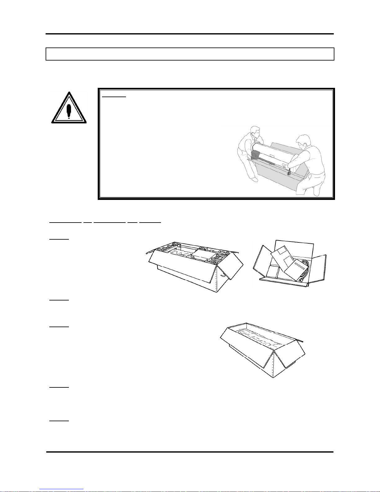
¾ Have two or more people unpack and assemble the printer.
¾ When lifting the printer out of the packing box, be sure to remove the vinyl cover first, then grab the
holding grips on the sides of the printer. Lifting the printer with the vinyl cover on may cause your
hands to slip and drop or damage the printer.
¾ Have two or more people transport the printer.
¾ Ensure that the plug has been disconnected from the power socket when it is not to be used for a long
time.
¾ Earth wires must be connected to wires or terminals that fulfil the conditions below.
o Earth terminals of power sockets
o Earth wires with copper morsel that is at least 650 mm under the ground
¾ Earth wires must be connected to wires or terminals that fulfil the conditions below.
¾ When setting roll media, place it on top of a desk or other flat surface. Setting roll media with the
scroller standing up may damage them.
¾ Keep the printer horizontal during transportation.
¾ Be sure to do the following before attaching options.
o Turn the printer off.
o Unplug the power cord from the socket.
o Unplug cables connected to the printer. Otherwise, damage to the printer or your computer may
occur.
o Remove electrostatic charge from your clothes and body by touching the metal parts of the printer.
o Electronic components such as the memory may malfunction if exposed to an electrostatic charge.
Page 12
Rockhopper 38 – User’s Guide
Page 12 AP-75038, Rev. 1.0. – 27/05/04
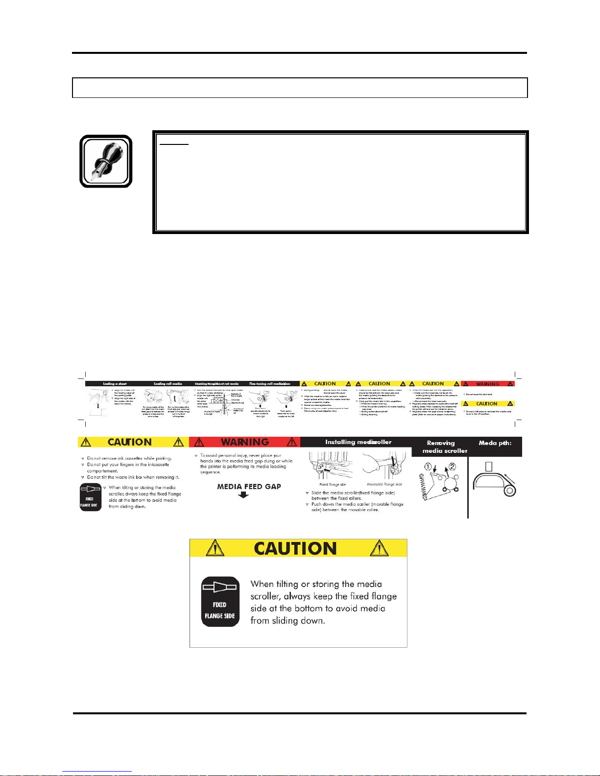
1.4. WARNING LABELS
Be sure to note the following when handling the labels.
Notes :
Make sure that all labels can be recognized. If text or illustrations cannot be seen
clearly, either clean or replace the label.
When cleaning labels, use a cloth with water or neutral detergent. Do not use a solvent
or gasoline.
If a warning label is damaged, lost or cannot be recognized, replace the label. When
replacing warning labels, contact your local MUTOH dealer.
Safety Labels are attached to the internal and external area of the printer to alert you to potentially
hazardous situations or conditions. The following safety labels are used in and on the printer:
La partie externe et interne de l’imprimante porte des symboles de sécurité destinés à attirer votre attention
sur des sources potentielles de danger ou des conditions pouvant être dangereuses. Les symboles de
sécurité suivants sont utilisés à l’intérieur et à l’extérieur de l’imprimante:
Auf der Innen- und Außenseite des Druckers sind Sicherheitssymbole angebracht, die Sie auf potentielle
Gefahrenquellen oder potentiell gefährliche Bedingungen hinweisen sollen. Im und auf dem Drucker werden
die nachfolgend aufgeführten Sicherheitssymbole verwendet:
Page 13

Rockhopper 38 – User’s Guide
Page 13 AP-75038, Rev. 1.0. – 27/05/04
2. PRODUCT OVERVIEW
2.1. GETTING TO KNOW THE PRINTER PARTS AND
COMPONENTS
Page 14
Rockhopper 38 – User’s Guide
Page 14 AP-75038, Rev. 1.0. – 27/05/04
N° Part Description
1 Cover
The protective cover protects the action environment. Opening the
cover immediately pauses printing which resumes when the cover is
closed.
2 Operation Panel
Positive touch keyboard with integrated LCD-Display.
3 Media Hold Lever
Lowers / releases pressure rolls to load / unload media.
4 Power switch
ON / OFF Power Switch.
Full shut down takes about 5 seconds.
5 Paper Basket
Media collecting basket prevents finished prints to fall on the floor
when they are sheet-off.
6 Print Plate
The print plate is a firm, flat base which supports the media during
printing.
7 Waste bottle
Collects Eco-Solvent Plus ink flow resulting from: purging, cleaning.
8
9
Paper Guide
The Paper Guide supports the media and incorporates the fixer (8;
heater element below printhead) and dryer (9; heater element)
10 Slip Ring
Prevent that Scroller to slip.
11 Eco-Solvent Plus ink
cassette slots
Hold / detect the Eco-Solvent Plus ink cassettes which are in use.
12 Scroller
Feeds through the roll media core to hold the media.
13 Scroller receiver
Set of 4 wheels which keeps the scroller into place.
Caution:
Do not put anything on the cover.
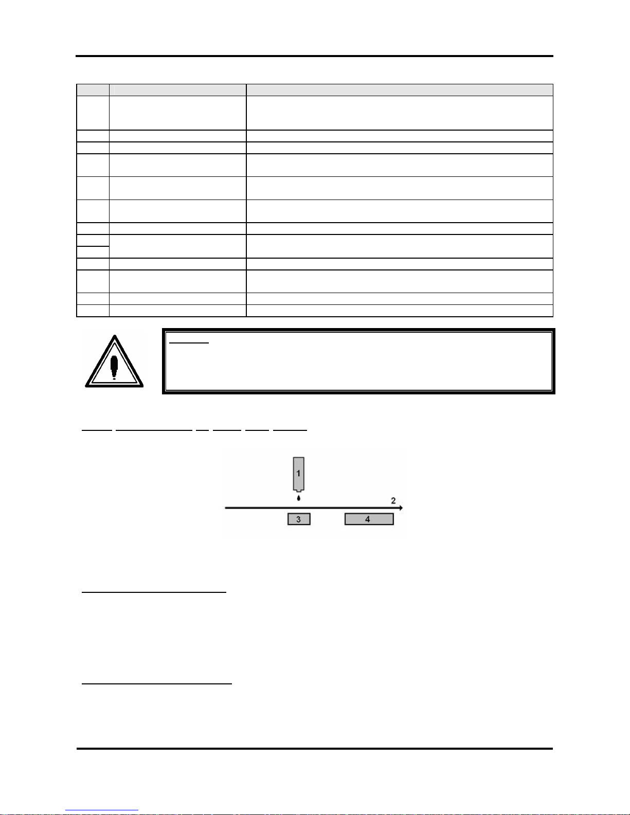
2.1.1
Explanation of fixer and dryer
Print Head
Media Direction
Fixer (Direct Heater)
Post Heater (dryer)
The FIXER will make it possible :
• To overcome the temperature gap between the room and the target printing temperature.
• To establish fast and immediate anchorage of the Eco-Solvent Plus inks onto/into the uncoated
substrate
• To optimize dot gain control on a wide media range
• To limit ink coalescence effect
The DRYER will make it possible
:
• To finalize the fixation process.
• Helps to make the prints touch-dry.
Page 15
Rockhopper 38 – User’s Guide
Page 15 AP-75038, Rev. 1.0. – 27/05/04
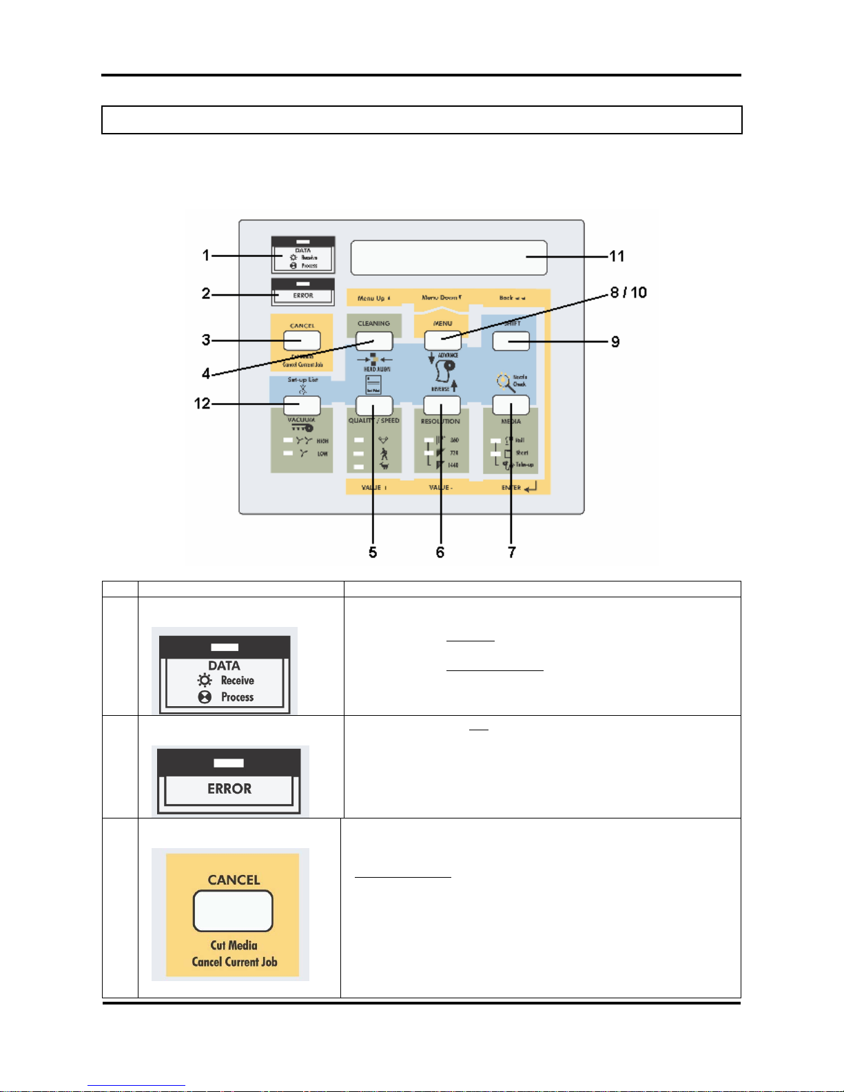
2.2. GUIDED TOUR AROUND THE OPERATION PANEL
Your printer is equipped with a direct access operation panel, meaning that all frequently use d functions can
be addressed directly from the keyboard.
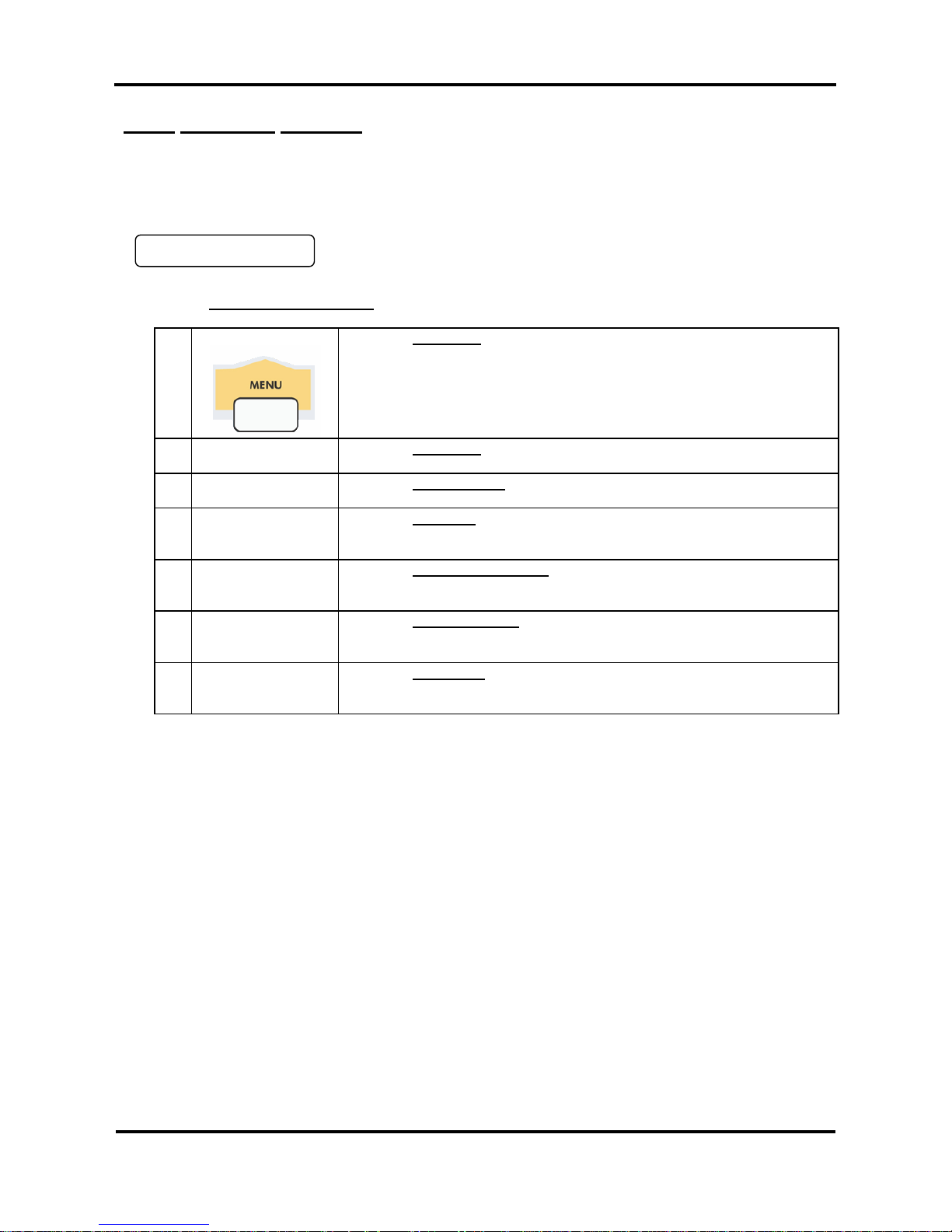
Nr. Key Description
1. Data LED :
The DATA LED monitors DATA status :
¾ LED ON
indicates data is being received.
¾ LED FLASHING
means data is being processed.
2. Error LED :
The ERROR LED is ON
after an ERROR has occurred, to indicate
a possible hazardous situation. The LED will go out if the error is
corrected or after pressing the [CANCEL] key.
3. Cancel Key :
The [CANCEL] key is a special key, controlling both the CANCEL
FUNCTION as well as the ROLL MEDIA sheet-off function.
Printer Condition
Result by pressing CANCEL
Idle Status Roll media is cut at the current position
Receiving Status Process stops
Process Status Buffer is cleared
Printing Status Print is cancelled, buffer is cleared,
printed part is cut-off.
Page 16
Rockhopper 38 – User’s Guide
Page 16 AP-75038, Rev. 1.0. – 27/05/04
To request a sheet-off, press cancel for 2 seconds and confirm
with [ENTER].
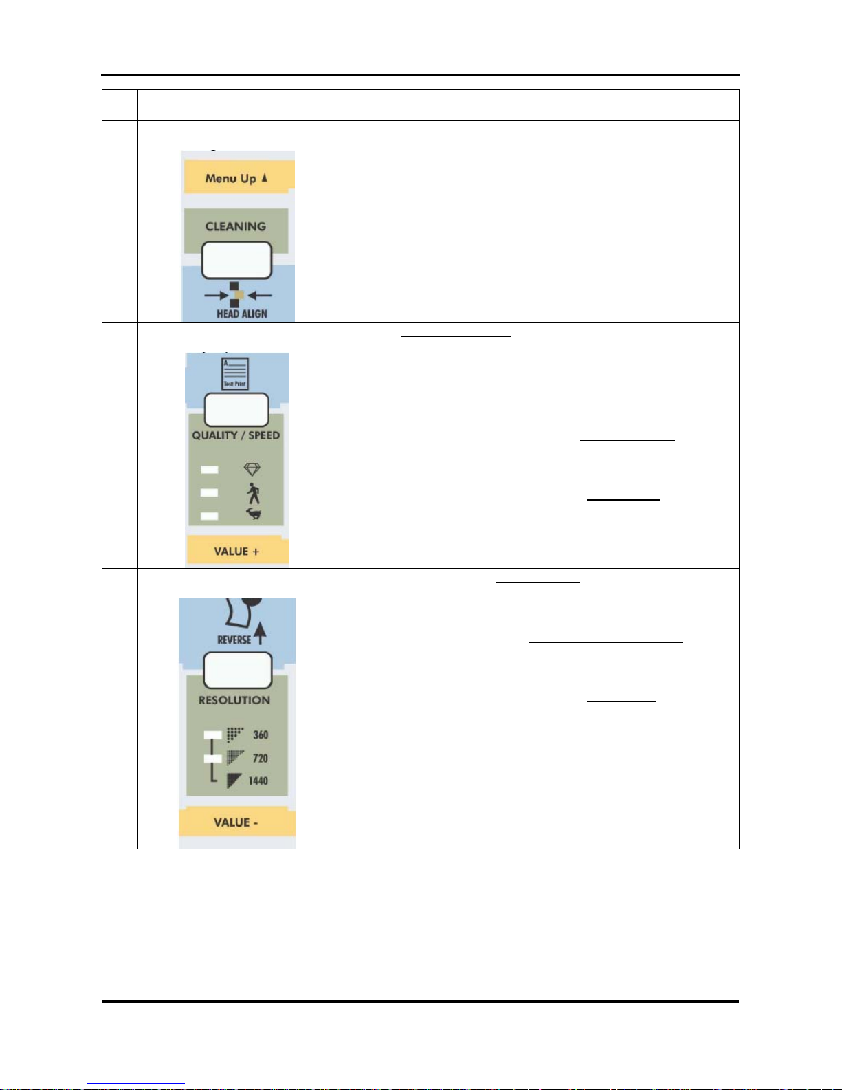
4. Cleaning :
¾ Pressing for 2 seconds initiates the cleaning
procedure.
¾ When pressed together with the [SHIFT] key
, (9) it
initiates the head adjustment procedure.
¾ Go to the Previous Menu, when in menu-mode
operation.
¾ For advanced Cleaning Control, enter the menu
system and select submenu [Utility] – option
[Clean].
5. Quality / Speed :
Pressing QUALITY / SPEED
will change the output quality and
speed. Each time the key is pressed you will notice the LED
indicator showing the current status : High quality, Normal and
High Speed.
¾ The set-up can only be changed in idle status.
¾ When pressed together with [SHIFT] key
(9)
outputs the Test Print.
¾ Go to the Next menu option, or increase a
parameter value when in menu-mode
operation.
¾ The LED indication is also influenced by data
coming from the RIP/driver software.
6. Resolution :
¾ Pressing RESOLUTION
will change the output
resolution between 360 DPI, 720 DPI or 1440 DPI.
The set-up can only be changed in idle status.
¾ When pressed together with the [shift] key
(9) it
allows reverse manual roll feed.
¾ Select the previous menu option and decrease a
parameter value when in menu mode
operation.
¾ If both LEDs are ON simultaneously the plotter
operates in one of the 3 available 1440 dpi modes
(horizontal, vertical or diagonal).
¾ The LED indication is also changed by data
coming from the RIP software.
Page 17
Rockhopper 38 – User’s Guide
Page 17 AP-75038, Rev. 1.0. – 27/05/04
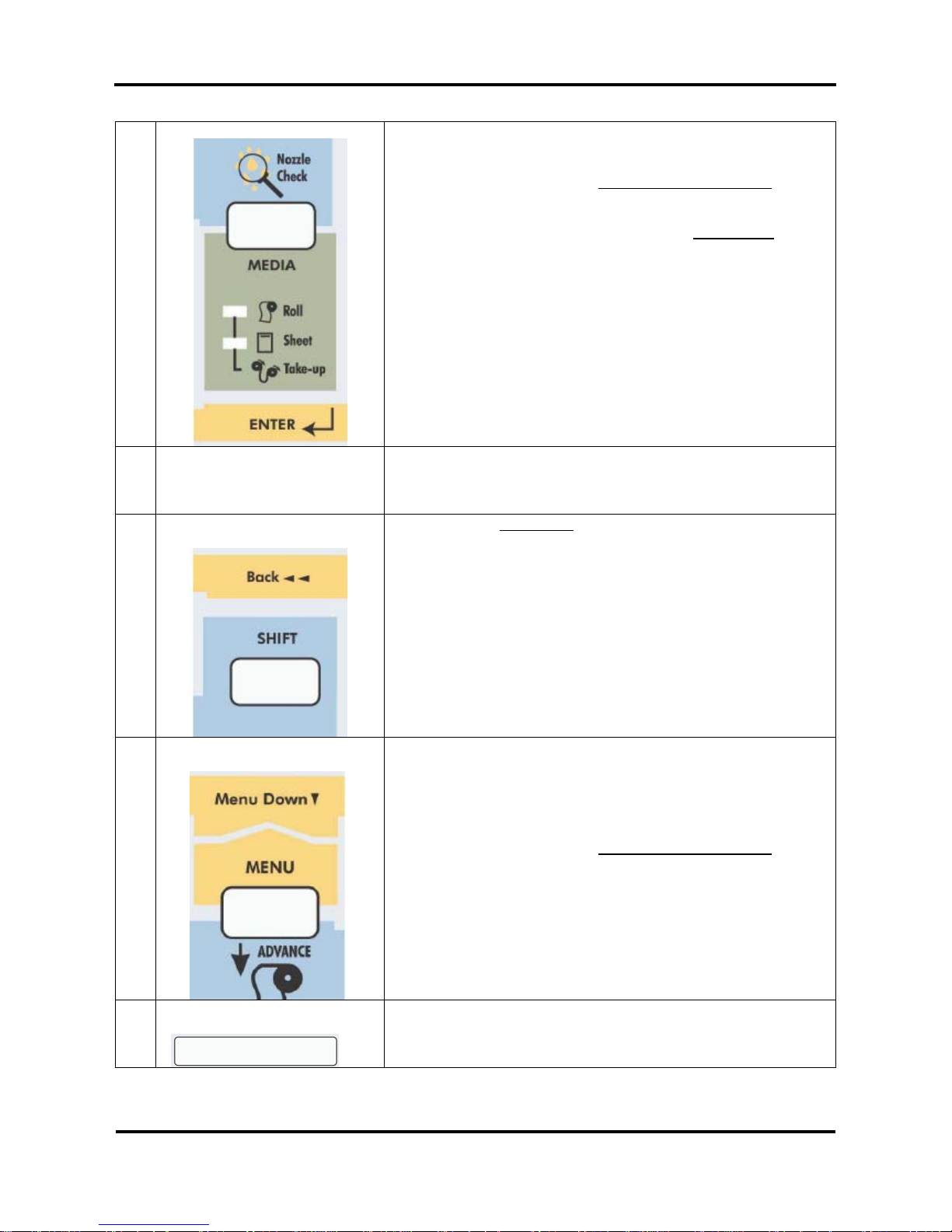
7. Media:
¾ Allows selection among roll, cut-sheet or media
take-up system support.
¾ When pressed together with the [shift] key
(9),
generates a nozzle check print.
¾ Accept a new setting when in menu mode
or enter
a lower menu level.
8. Menu Mode Operation : The Menu Mode Operation is used to change printer settings and
parameters. Menu Mode related buttons are enclosed in the
yellow area.
9. Shift-button :
¾ Shift button
to activate Head Adjustment, manual
roll feed (forward or reverse), Nozzle check print,
Test print or Set-Up List.
¾ Back out of menu levels or switch back to ONLINE
level from top level (Menu mode operation).
10. Menu :
¾ The Menu Mode Operation is used to change
printer settings and parameters.
¾ Press the [MENU] key to switch from ONLINE
status to menu mode operation.
¾ When pressed together with the [shift] key
(9) it
allows forward manual roll feed.
11. Liquid Crystal Display :
16 characters LCD display which displays messages, shows
settings / values and allows menu-wise control.
Page 18
Rockhopper 38 – User’s Guide
Page 18 AP-75038, Rev. 1.0. – 27/05/04
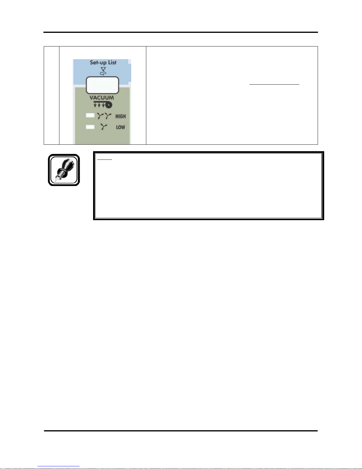
12. Vacuum :
¾ The Vacuum key allows you to reduce the fan
power when using very light media such as
synthetic paper or uncoated paper lighter than 70
g/m².
¾ When pressed together with the [SHIFT] key
, (9) it
initiates a Set-up List and an adjustment
parameter plot.
Note :
When the data light is ON (receiving) or blinking (processing), all the keys are disabled,
except the head cleaning key.
The keys will be operational in case of receiving data while you are in the setup menu.
The setting changes, however, will then only be valid for the next printing job.
Panel set up from the printer is only possible when no printing data or processing data is
sent through the printer.
In menu mode operation, the shift key functions are not usable.
Page 19
Rockhopper 38 – User’s Guide
Page 19 AP-75038, Rev. 1.0. – 27/05/04
2.2.1. Keyboard Concept
The Menu Mode Operation is used to access settings which cannot be controlled via the direct access ke ys.
As soon as media is loaded, the printer is ONLINE and ready to receive data.
The display shows:
In case no media is loaded, the printer is OFFLINE. To enter the MENU MODE, however, you have to make
sure that the media hold lever is down.
1 Menu:
Press the Menu Key
to switch from ONLINE status to menu mode
operation.
2 Menu Down À:
Press the Menu Key
to go to the NEXT menu.
3 Menu Up ¿:
Press the Cleaning Key
to go to the Previous menu
4 Back ½½:
Press the Shift Key
to back out of menu levels or to switch back to
online when in top menu level.
5 Value +:
Press the Quality / Speed Key
to select the next menu option or to
increase a parameter value.
6 Value -:
Press the Resolution Key
to select the previous menu option or to
decrease a parameter value.
7
ENTER
↵:
Press the Media Key
to ACCEPT a new setting or ENTER a next MENU
LEVEL.
Plot OK
Page 20

Rockhopper 38 – User’s Guide
Page 20 AP-75038, Rev. 1.0. – 27/05/04
2.2.2. Menu Structure - overview
Command MH-GL2 / MHGL, GL2 /
RTL-PASS
Printer command language
selection
PlotArea Normal / Expend Set-up hard clip area
depending of media size.
Position P1 / Full / LL Set-up initial pen position in
MH-GL, GL2 and MH-GL2.
Terminat Special / Normal Command Language
terminator selection.
Resolut 720dpi / 360dpi / 300dpi Select logical resolution.
OnlineTimer Off / 10s / 20s / 30s /
40s / 50s / 60s / 90s / …
/ 780s / 800s
In case of intermittent data
flow, determines time-out to
finalize plot.
Overwrite Last / Mix Set-up control of overlapping
areas.
Command
OriginReset No / Yes Allows manual nesting when
combined with backward feed.
InkDryTime 0 sec to 5 sec to 30 sec
to 60 min.
Set-up ink drying time before
sheet-off occurs.
Halftone Quality / Speed / Thin Select method of pseudo-tone
processing.
KCMY→KMY
Yes / No Reserved for future use.
CMY→Black
Yes / No Allow mixed black (CMY) or
not.
KYCMYK No / Yes Reserved for future use.
Scale 25% to 100 % to 400% Expand or reduce print data.
Mirror Off / Y On Reverse printing set-up.
Direct. Command / MAX-MIN Media size determined by
Page size Command or by
plot data.
Cut Position Data / Standard Specify cutting position on roll
media following data or
standard media size.
MediaCut Auto / Off / Manual Automatic sheet-off set-up.
Copy 1 to 99 Set-up number of copies.
InkDensity Normal / Micro Select Normal or Micro dot
drop size in function of media
& ink type.
Dist.Adj No / Clear / Change /
Confirm
Plot distance adjustment.
Function
StepAdj Change / Clear Micro-banding elimination via
microstep adjustment.
Mode Bi Centro / Centro Select between uni-directional
and ECP high speed.
Centro
Timing A – B / B – A Select ACK timing for BUSY
state.
Network IP Address 000.000.000.000 to
192.034.041.015 to
255.255.255.255
ErrorDisplay Off / On Show or hide simple error.
No Initialize printer set-up.
Yes InitialAll No / OK Initialize printer set-up.
InitialCommand No / OK Initialize printer set-up.
InitialFunct No / OK Initialize printer set-up.
InitialCentro No / OK Initialize printer set-up.
Initialize
InitialNetwork No / OK Initialize printer set-up.
Dump Start – End / All (Cancel
with CANCEL-key)
Set-up data dump mode.
Wash Starts manual head wash
before ink type switching.
Normal Starts a NORMAL cleaning Clean
Powerful Starts a POWERFUL cleaning
No Fill
Yes Starts a Ink Fill Sequence
Ink Change No / Yes Starts ink Change Procedure
Online
Utility
Maintenance
Rec.
Prints maintenance record.
Page 21
Page 21 AP-75038, Rev. 1.0. – 27/05/04
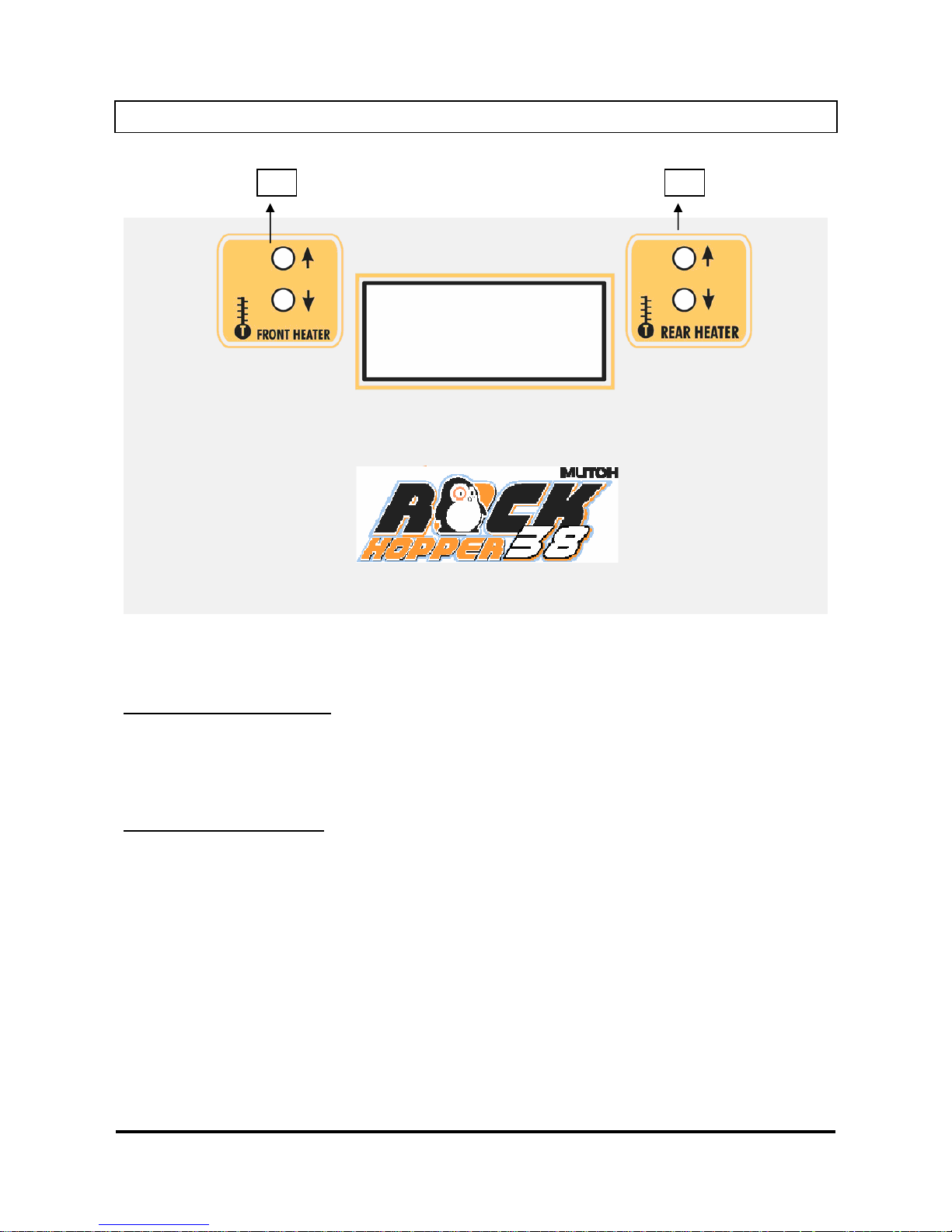
2.3. HEATER SYSTEM OPERATION PANEL
1 = Controls Direct Heater / Fixer
2 = Controls Post Heater / Dryer
Controls Direct Heater / Fixer:
Set temperature for the direct heater / fixer. Real (RT) and set (ST) temperature are displayed on the LCD
screen.
The maximum temperature is 70 °C. By pushing the buttons you can select an appropriate temperature.
Controls Post Heater / Dryer:
Set temperature for the post heater / dryer. Real (RT) and set (ST) temperature are displayed on the LCD
screen.
The maximum temperature is 50 °C. By pushing the buttons you can select an appropriate temperature.
Page 22

Rockhopper 38 – User’s Guide
Page 22 AP-75038, Rev. 1.0. – 27/05/04
Page 23
Rockhopper 38 – User’s Guide
Page 23 AP-75038, Rev. 1.0. – 27/05/04
3. SETTING UP THE UNIT
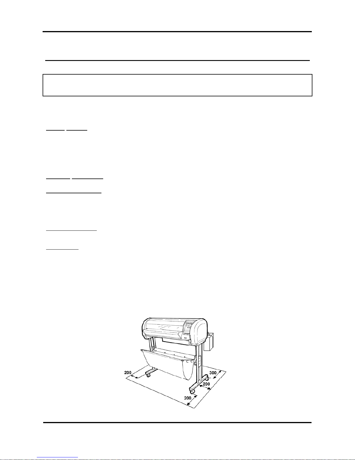
3.1. INSTALLATION REQUIREMENTS: SELECTING AN
ADEQUATE PLACE FOR SETTING UP YOUR EQUIPMENT
The location where you set up your equipment is very important. Please see to it that it meets following
conditions:
Power supply:
- Voltage: 200 to 240 VAC or 100 to 120 VAC
- Frequency: 50/60 Hz ± 1 Hz
- Current: < 10 A (110 V)
< 5 A (220 V)
Ambient conditions:
Operating environment
- Temperature: 18°C to 35°C
- Humidity: 20% - 60% non-condensing
- Recommended working environment
Temperature: 22-30°C
Humidity: 40-60%
Storage environment
- Temperature: -10°C to 60°C
- Humidity: 20% - 85% non-condensing
Variation rate
- Temperature: 2°C per hour
- Humidity: 5% per hour
¾ Avoid using your Rockhopper 38 printer near heating systems, such as stoves or heaters.
¾ Avoid using your printer under strong lighting, such as halogen lamps, light bulbs or direct sun light.
When selecting a place for your printer, leave at least 200 mm in front and at the sides, and 300 mm at the
rear, as shown in the illustration below.
Page 24
Rockhopper 38 – User’s Guide
Page 24 AP-75038, Rev. 1.0. – 27/05/04
3.2. WHAT’S IN THE BOX?
What’s in the box ?
¾ Rockhopper 38 printer unit
¾ Printer stand (packed separately)
¾ 1 Paper scroller (3”) including plastic flanges
¾ 1 Sheet-off knife, pre-installed in head
¾ Media Collection Basket
¾ Starter Software Kit
¾ Scroller Slip Ring
Accessories kit consisting of:
¾ Power cable
¾ Set of Eco-Solvent Plus ink cassettes (CMYK)
¾ User’s guide
¾ Waste bottle
¾ Extra Box with Roll Take-Up System (optional)
¾ Cleaning cartridges
Page 25
Rockhopper 38 – User’s Guide
Page 25 AP-75038, Rev. 1.0. – 27/05/04
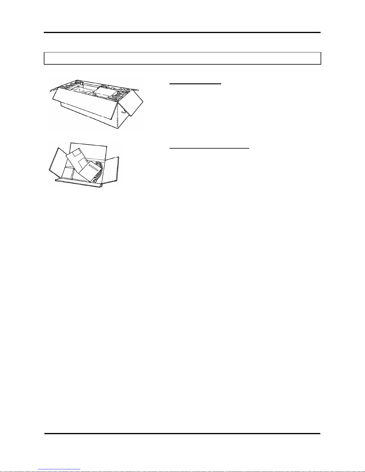
3.3. UNPACKING YOUR ROCKHOPPER 38 PRINTER
The printer body and printer stand are packed in two separate boxes. Unpack the printer body first.
Caution:
When unpacking the printer, check whether all parts described in the parts list are
included in the box. Consult your dealer if anything seems to be missing.
Lifting the machine out of the box should
be done by two people.
Protect the printer from shocks.
Do not dismantle the unit.
Procedure for unpacking the printer:
Step 1:
Open the printer body box.
Take out the accessories box and
scroller.
Step 2:
Open the accessories box and take out the User’s guide.
Step 3:
Remove the pieces of foam protecting the printer body during
transportation.
Step 4:
Remove all plastic materials wrapped around the printer.
Step 5:
Open the printer stand box. Check whether all parts described in the parts list are included in the box.
Consult your dealer if anything seems to be missing.
Page 26
Rockhopper 38 – User’s Guide
Page 26 AP-75038, Rev. 1.0. – 27/05/04
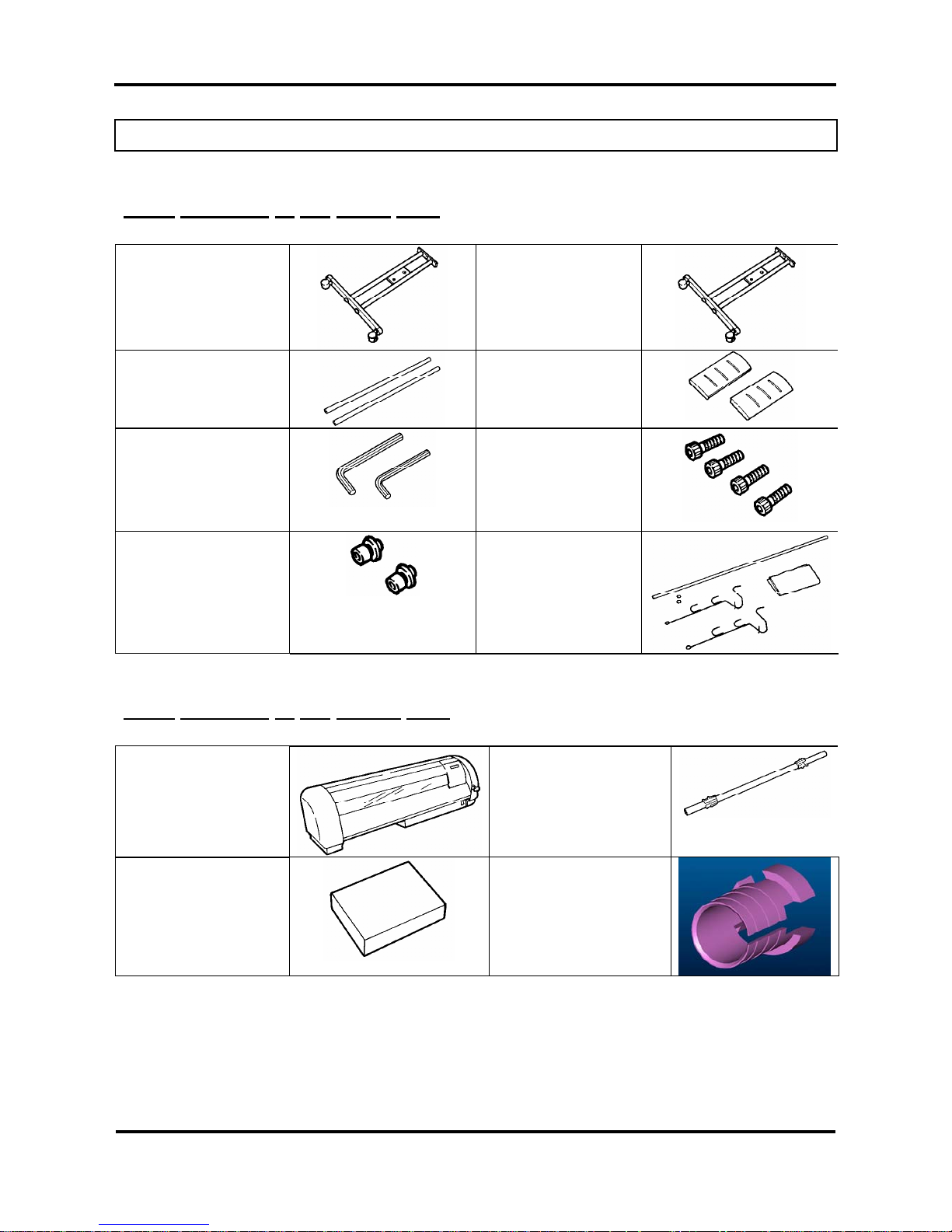
3.4. PARTS LIST
3.4.1. Contents of the stand box:
Stand leg (left)
(1 pc)
Stand leg (right)
(1 pc)
Cross bar (2 pcs)
Plastic cover
(2 pcs)
Hexagon wrench
(1 large & 1 small)
Hexagon bolt (long) (4
pcs)
Hexagon bolt (short) (2
pcs)
+ premounted washers
Paper basket
assembly
(1 set)
3.4.2. Contents of the printer box:
Printer unit (1 pc)
3” Scroller (flange on
both sides) (1 set)
Accessories box
Slipring (1 pc)
Page 27
Rockhopper 38 – User’s Guide
Page 27 AP-75038, Rev. 1.0. – 27/05/04
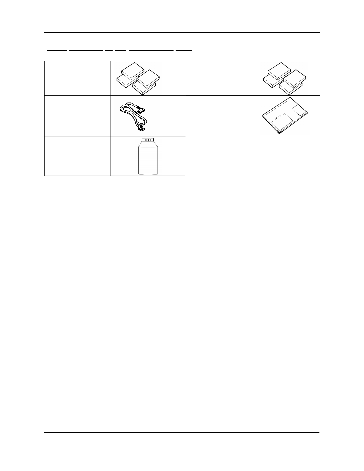
3.4.3. Contents of the accessories box:
Cleaning cartridges (4
pc)
Eco-Solvent Plus ink
Cassettes
(C,M,Y,K)
(1 each colour)
Power cable (1 pc)
User’s Guide
Waste bottle + waste
bottle bracket
Page 28
Rockhopper 38 – User’s Guide
Page 28 AP-75038, Rev. 1.0. – 27/05/04
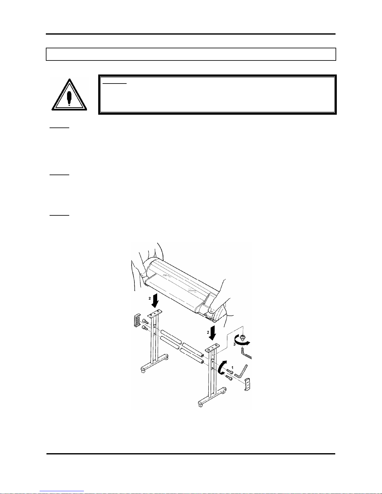
3.5. ASSEMBLING THE PRINTER
Caution:
Before lifting the printer body out of the box, make sure to remove all plastic wrapping
materials first, in order to avoid that the machine slips from your hands.
Step 1:
Unpack the stand and assemble it by screwing the left and right stand legs to the cross bars. To do this, use
the 4 long hexagon bolts and the large hex wrench provided. Make sure the leg welding points outwards and
the caster wheels are on the front. After securing the bolts permanently, put on the two plastic side covers.
(See 1 on figure below).
Step 2:
Place the printer onto the stand. The bottom part of the printer body has 4 spherical knobs that exactly fit
into the stand holes. Note that the front side of the stand is the side where the lockable caster wheels are
located. (See 2 on figure below).
Step 3:
Secure the printer body onto the printer stand using the 2 short bolts and the small hexagon wrench
provided. (See 3 on figure below).
Page 29

Rockhopper 38 – User’s Guide
Page 29 AP-75038, Rev. 1.0. – 27/05/04
Step 4:
Loosen the wing screw which is fixed to the printing table (4) and remove the metal fixing plate (5) protecting
the printer head during transportation. (See 4 & 5 on figure below). Keep the metal fixing plate and wing
screw, since the printing head needs to be blocked during any transportation of your printer.
Caution:
Take care not to drop the wing screw inside the printer body. Should it fall in, do not
boot up your printer until the wing screw has been safely removed.
Remove the white tape that locks the sheet-off mechanism during transportation
(See 6 on figure below).
Step 5:
Remove the cable block between rail and cover (7).
Remove the lever block (8).
Page 30
Rockhopper 38 – User’s Guide
Page 30 AP-75038, Rev. 1.0. – 27/05/04
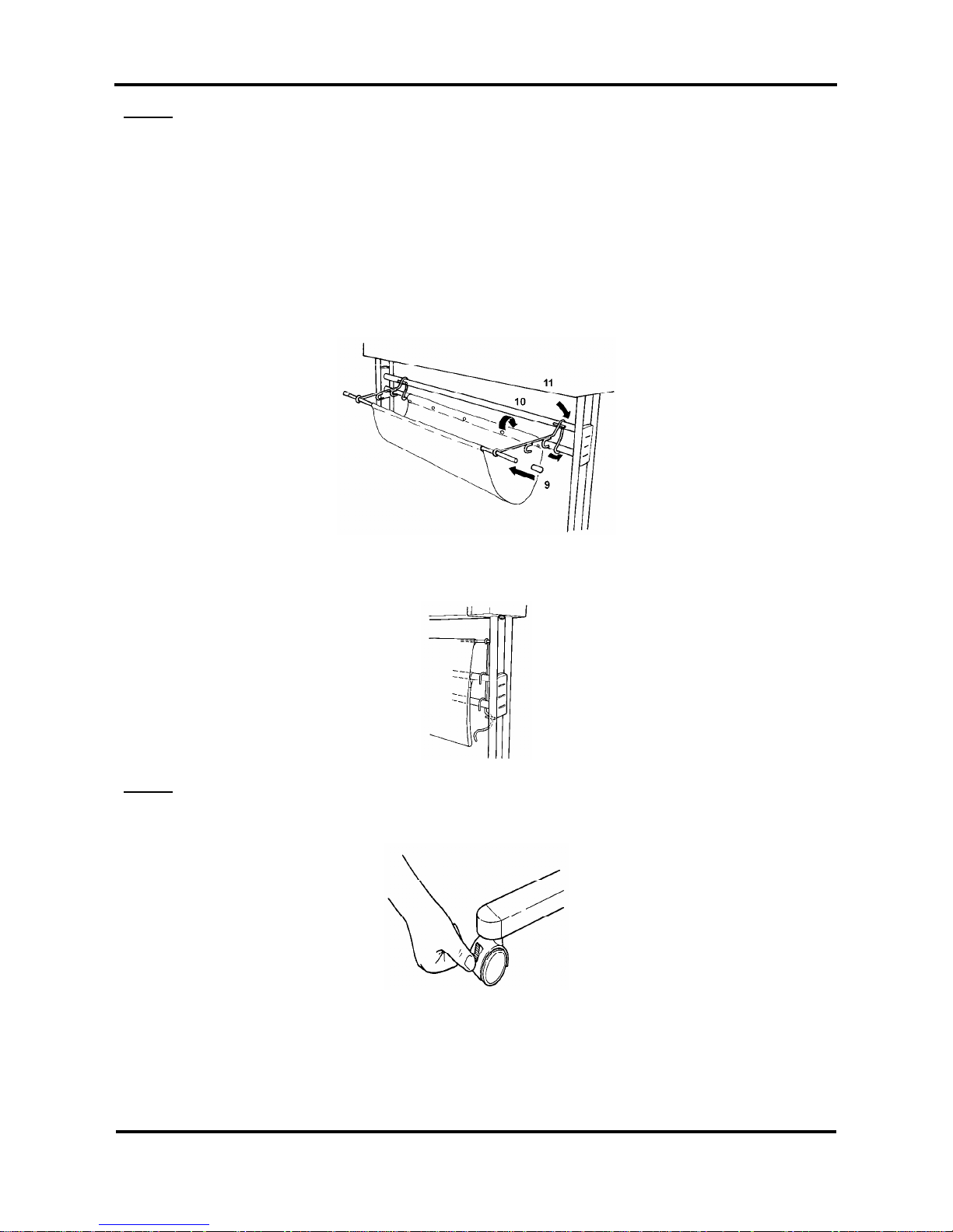
Step 6:
Assemble the paper basket as follows :
Insert the metal bar into the small sleeve of the cloth basket. Then put on the two metal basket supports to
the left and the right side. Next insert the end caps onto the metal bar. (See 9 on the figure below).
Attach the cloth basket around the lower cross bar of the stand by way of the push buttons. (See 10 on the
figure below).
Secure the paper basket to the printer stand. Fix the front hook of the metal basket supports over the upper
cross bar of the stand, then in-between the two cross bars and finally under the lower cross bar. (See 11 on
the figure below).
The extra hooks provided on the metal basket supports are meant to stack your paper basket vertically along
the legs of the printer.
Step 7:
After setting up the printer, wheel it to the desired location and lock the caster wheels.
Page 31

Rockhopper 38 – User’s Guide
Page 31 AP-75038, Rev. 1.0. – 27/05/04
3.6. INSTALLATION OF THE WASTE BOTTLE
In the accessories box, you will find the Waste Bottle Bracket together with the Waste Bottle.
After unpacking and assembling the Rockhopper 38 printer, you must in stall the Waste Bottle Bracket with
the Waste Bottle.
Important :
Do NOT power on the unit before installation of the Waste Bottle.
Please follow the instructions below to install the Waste Bottle.
Step 1 : Screw the Waste Bottle Bracket onto the Scroller System on the left side standing at the rear of
the unit. (2 screws) (Please refer to picture A on the following page.)
Step 2 : Remove the adhesive tape holding the Waste Tubes to the unit.
Step 3 : Push the big Waste Tube in the hole in the middle of the top of the bracket. Check if the tube is
fixed securely. (Please refer to picture A on the following page.)
Step 4 : For the 2 smaller tubes, do as follows :
¾ Slide the upper plastic ring upwards.
¾ Loosen the lowest plastic ring.
¾ Insert the waste tube in one of the two remaining holes.
¾ Fix the tube by sliding the plastic ring back to the tube.
¾ If necessary lower the upper plastic ring.
¾ Check if the tube is locked securely.
¾ Repeat point 1 to 7 for the other small tube.
1 : plastic rings on small tube 3 : Top Waste Bottle Bracket
2 : big waste tube 4 : Top Waste Bottle
(Please refer to picture A mentioned below.)
Step 5 : Connect the connector of the Waste Bottle Sensor. (Please refer to picture A mentioned below.)
Page 32

Rockhopper 38 – User’s Guide
Page 32 AP-75038, Rev. 1.0. – 27/05/04
Picture A :
1. Big waste tube
2. 2 thin waste tubes
3. Screws to mount Waste Bottle Bracket
4. Top Waste Bottle Bracket
1 2 3 4
Page 33

Rockhopper 38 – User’s Guide
Page 33 AP-75038, Rev. 1.0. – 27/05/04
4. PREPARING FOR A JOB
4.1. CONNECTING THE POWER CABLE
Step 1 : Make sure the printer’s power switch is turned OFF.
Step 2 : Plug the printer-end of the power cable into the connector at the back of the printer.
Step 3 : Plug the other end of the power cable into an electrical outlet of the correct voltage and with a
proper grounding.
Power supply:
• Voltage:
100-120V 200-240V
• Frequency:
50/60 Hz 50/60 Hz
• Current:
6.8A 3.4A
Note:
When you turn off the power, please note that your printer needs about five seconds to
perform its shut down sequence.
To this end, wait for at least five seconds to switch the printer on again.
The disconnect device is the plug on the power supply.
Page 34

Rockhopper 38 – User’s Guide
Page 34 AP-75038, Rev. 1.0. – 27/05/04
4.2. CONNECTING THE INTERFACE CABLE
Caution:
When connecting the printer to your computer, make sure that both your printer and
your computer are switched OFF.
Note:
For optimum output, please use a cable recommended by Mutoh.
The printer can use the Centronics interface (IEEE1284 compatible, Nibble, ECP). Connect to the printer as
shown in the following diagram with an interface cable (option) for the connection system you will use.
Connect to the host computer with another interface cable.
Note:
The use of an unnecessary long cable may influence your data transmission. Therefore,
keep your interface cable as short as possible.
An Ethernet board RJ-ETH14TX (for networking) is available as an optional extra.
4.2.1. Tips to use high-speed ECP parallel communication
¾ If the parallel port setting on the printer is set to BI CENTRO (See Menu Mode Operation – Menu
Structure Overview) your printer is ready for high-speed bi-directional communication.
¾ In order to be able to use this high-speed mode without problems please note:
Computer Bios for parallel port should be set to ECP
Only use a shielded and balanced parallel cable, which is IEEE 1284 compliant.
If your RIP software is protected with a hardware lock (dongle), which needs to be placed on the
parallel port, it is best to have available 2 parallel ports.
• One port to connect: hardware lock, scanner, external drive or CD-ROM,…
• One port (ECP) directly connected to the printer.
In case either of the above mentioned topics is not respected you may encounter all kinds of printer artefacts
such as: unexplainable error messages, sheet-off during printing, unexpected media feed during printing,
etc…
If this occurs, switch your system to unidirectional parallel communication.
Set print parallel port to Mode > CENTRO
Set computer parallel port Bios to SPP or EPP
The data transfer will then slow down and the artefacts will disappear. Before switching back to the highspeed bi-directional parallel mode, have your computer system examined closely by a trained computer
technician.
Page 35

Rockhopper 38 – User’s Guide
Page 35 AP-75038, Rev. 1.0. – 27/05/04
4.3. LOADING ECO-SOLVENT PLUS INK CASSETTES (FIRST
TIME)
Important :
Before installing Eco-Solvent Plus ink cassettes in your new Rockhopper 38
printer, it is necessary to clean the Rockhopper 38 with special Eco-Solvent Plus
Cleaning Liquid.
Before transportation (e.g. service) it is necessary to clean the Rockhopper 38
(which used Eco-Solvent Plus ink) with special Eco-Solvent Plus Cleaning
Liquid.
When the machine returns or is installed at another place, perform again a
cleaning with the special Eco-Solvent Plus Cleaning Liquid.
Please only use the Eco-Solvent Plus Cleaning liquid. Using other cleaning
cassettes will result in clogging of ink in the machine. As a result all internal
ink-passages must be replaced.
Note :
When loading Eco-Solvent Plus ink for the first time, please make sure to have four
Eco-Solvent Plus Cleaning liquid cassettes.
Before installing Eco-Solvent Plus ink cassettes in your new Rockhopper 38 printer, it is necessary to clean
the Rockhopper 38 with special Eco-Solvent Plus Cleaning Liquid.
To do so, please follow the instructions mentioned below.
Step 1:
Power ON the unit.
Step 2:
Slide the four Eco-Solvent Plus Cleaning liquid cassettes into their cassette
position. Automatic detection of cleaning cassettes occurs due to label
recognition.
Step 3:
Press the [VALUE +] key or [VALUE -] key to select “Yes” and press
ENTER.
Note :
Please note that the Rockhopper 38 printer has two print heads (K, CMY). A head
wash cycle is done per print head. This means that the first head wash cycle is
performed for the K print head only, and then a head wash cycle is performed for the
CMY print head.
[YMCK] discharge
Wash: Black&Colour
Page 36

Rockhopper 38 – User’s Guide
Page 36 AP-75038, Rev. 1.0. – 27/05/04
Step 4:
The unit is cleaning the K print head.
.
Step 5:
Remove the Black (K) Eco-Solvent Plus Cleaning Liquid cassette.
Note :
Only remove the Black (K) Eco-Solvent Plus cleaning liquid cassette (Not all four Eco-
Solvent Plus cleaning liquid cassettes). Removing all Eco-Solvent Plus cleaning liquid
cassettes could cause the printer to lock-up. If this is the case, please re-insert the
Eco-Solvent Plus cleaning liquid cassettes into the CMY cassette slots to recover the
ink load procedure.
Step 6:
The unit is cleaning the CMY print heads.
Step 7:
Remove the Eco-Solvent Plus Cleaning Liquid cassette from the CMY
slots.
Step 8:
The rest of the cleaning fluid in the printer unit is discharged when cleaning
cassette is removed.
Step 9:
Empty the waste ink box from the printer.
Step 10:
Insert the four Eco-Solvent Plus ink cassettes one by one in the correct
slot.
Step 11:
Eco-Solvent Plus ink is being loaded into the ink supply system (tubing +
heads).
Note :
Please wait after loading Eco-Solvent Plus Ink for about 1 hour before start printing.
The printer is now ready to print.
Head Wash
Remove Bk Wash Cart
Head Wash
Remove Co Wash Cart
Head Wash
Change Waste ink
[CMYK] discharge
Ink refill 4M
Page 37

Rockhopper 38 – User’s Guide
Page 37 AP-75038, Rev. 1.0. – 27/05/04
4.4. LOADING MEDIA
4.4.1. General recommendations with regard to printer media
¾ For best quality output and printing results on your Mutoh Rockhopper 38 Eco-Solvent Plus printer, it is
recommended to use MUTOH media.
¾ For printing onto uncoated media, the temperature that can be reached on top of the media is important
to obtain the right output quality and ink fixation. Note that the temperature reached on top of the media
depends on the heater settings, the heat capacity of the media which is used and the exposure time (=
time the media is exposed to heat), which is influenced by the output mode, printing width and ink setup.
¾ Lower cost self-adhesive PVC media are produced with a normal clay coated paper backing. This
backing paper tends to dry out because of the heating and may start to cockle. This phenomenon can
be overcome by reducing the heating temperature or by selecting a media with a PE-coated backing
paper.
¾ It is strongly recommended to acclimatize your media before printing on it. Ideally, bring the media rolls
in the neighbourhood of the printer 24 hours on beforehand. Bringing in cold media and printing on it
usually results in inferior output quality because of the big temperature gap that needs to be overcome.
We recommend a working environment with a temperature between 22° C and 30° C and a humidity
between 40% - 60% (without condensation).
¾ We recommend you to wear cotton gloves to avoid fingerprints on the media.
¾ Always make sure that you are printing on the correct side (printable side) of the media.
4.4.2. Loading cut sheet media
Step 1:
Open the cover and verify that the hold lever is in the UP position.
Step 2: Selecting the media
Press the Media-key to select media loading sequence with roll
take-up system (Both LEDs ON).
By pressing the key you will see the LEDs alternate between three
choices (sheet, roll and take-up). Now select roll take-up loading
sequence (both LEDs ON).
Now select sheet
Note:
When making the wrong media selection choice by selecting roll when a cut -sheet is
being loaded, the printer will give the roll media end warning when the end of the cutsheet is reached, and printing will not be finished normally.
Step 3: Installing the media
Insert the media, which has already been acclimatized, between the pressure roller system and the drive
roller.
Page 38

Rockhopper 38 – User’s Guide
Page 38 AP-75038, Rev. 1.0. – 27/05/04
Step 4:
Align the right side of the media with the base line (holes), as shown in the figures.
Align the media with the leading edge of the printing plate.
Align the right side of the media with the baseline holes. You are
allowed about 5 mm of play to the right and left of the centre of
the base line holes.
Please examine the position of the left side of the media and compare it with the illustrations below.
There is not enough clearance between the media edge and the
pressure roll (less than 5 mm), which may cause a media jam or
damage if the media slightly shifts during printing.
Media is set correctly, it is held down completely by the pressure
roll. Even slight shifting will not cause media damage or a
media jam.
Media is set correctly. There is at least 5 mm clearance
between the pressure roller and the media edge.
Important:
The base line is just a guideline. You are allowed about 5 mm of play to the left
and right of the centre of the base line holes. This play allows you to correctly
load the media as described under step 4.
Page 39

Rockhopper 38 – User’s Guide
Page 39 AP-75038, Rev. 1.0. – 27/05/04
Step 5:
Lower the media hold lever by tilting it down(wards).
Notes:
Always remove the roll media and scroller from the scroller receiver before loading a cut
sheet.
Install your media straight. If you do not do this, the printer might misread the actual
media size, resulting in abnormal printing.
When the roll media indicator is ON while a cutsheet is loaded, this indicates a media
selection error
and printing will not be finished normally.
You can install a cut sheet both in the horizontal and in the vertical direction, except for
A0 size cut sheets. This size can only be installed in the vertical direction.
The media has a printing side and a non-printing side.
If you print on the non-printing side, this may influence the quality.
The printable side is normally whiter.
Step 6:
Close the cover. The head starts moving automatically to detect the media size.
Step 7:
When media is loaded correctly and the printer is ready to receive data, the display shows the message:
Step 8:
Removing the media
Open the cover, tilt the media hold lever UP, and remove the media.
Note:
During plotting, media detection, cutting and cleaning always keep the media hold lever
down.
If the print head is not situated at the maintenance position, the media hold lever cannot
be lifted UP.
Do not move the print head while the hold lever is UP.
Roll Media End
Media Initialization
Plot OK
Page 40

Rockhopper 38 – User’s Guide
Page 40 AP-75038, Rev. 1.0. – 27/05/04
4.4.3. Loading roll media
Step 1 : Open the cover, check that the head is in a position where it will not touch the media keeper
blade and put the hold lever up.
Step 2 : Selecting the media
Press the Media-key to select media loading sequence with roll
take-up system (Both LEDs ON).
By pressing the key you will see the LEDs alternate between three
choices (sheet, roll and take-up). Now select roll take-up loading
sequence (both LEDs ON).
Now select roll
Note :
When making the wrong choice by selecting cut-sheet when a roll is loaded, the printer
will pull off the maximum cut-sheet length, searching the back edge. Finally the printer
will report a media search error.
Step 3 : Take your roll of media.
Step 4 : Remove the movable flange from the scroller by
pulling it off.
Step 5 : Load the media over the scroller
Turn the roll media as shown in the diagram and pass it over the scroller until the media tube fits
firmly over the fixed flange. Replace the movable flange on the scroller and fit it firmly into the
media tube.
Page 41

Rockhopper 38 – User’s Guide
Page 41 AP-75038, Rev. 1.0. – 27/05/04
Note:
Do not drop the media roll over the scroller as this might damage the scroller end caps.
All Mutoh recommended roll media are rolled up with the printable side facing the
outside, so that you can load the roll media easily.
When the cut sheet indicator light is ON when loading a roll, the printer will display a
media search error after feeding the media for about 3m.
Step 6 : Installing the scroller slip ring
Install the scroller slip ring onto the scroller. Slide the scroller slip ring on the left side of the
scroller (side with fixed flange).
Step 7 : Installing the scroller
Install the scroller as follows:
Stand at the back side of the printer, holding the scroller with the fixed flange side in your left
hand. Slide the scroller (left side) into the scroller receiver, as shown in the illustration. Push the
scroller (Right side - movable flange side) down into the right scroller receive r. You will noti ce it
dropping nicely into place.
Step 8 : Locking the scroller slip ring
Lock the scroller by sliding the scroller slip ring onto the scroller rollers. The scroller slip ring will
prevent unwinding of the roll media from the scroller when roll media is still not loaded in the
machine.
Page 42

Rockhopper 38 – User’s Guide
Page 42 AP-75038, Rev. 1.0. – 27/05/04
Step 9 : Loading roll media
Pull some media off the roll, feed it into the media feed gap and
between the pressure rollers and the drive roller.
Pull out the media at the front side and make sure at least 0.5
meters hangs out in front of the printer.
Caution:
When you load roll media from the back, be careful not to hurt yourself by touching the
pressure roll system.
Step 10 : Checking the position of roll media
Turn the scroller by hand and wind up several turns of roll media. As you wind up the media, check the
relative positions of the drive roller on the right and the right hand edge of the roll media. It is normal if with
the roll media pulled tight, the portion that is being wound and the portion that was unwound are straight and
the right hand side edge of the media is on the guide line. If this is not the case, adjust the position of the roll
media in accordance with step 9.
Guide line (holes) can be seen Guide line (holes) is hidden
Step 11 : Fine-tuning the roll media position
If the guide line (holes) can be seen, the roll media must be moved to the right.
If the guide line (holes) is hidden, the roll media must be moved to the left.
Turn the scroller receiver screw counter -clockwise to move
the roll media to the right (when standing in front of the
printer).
Page 43

Rockhopper 38 – User’s Guide
Page 43 AP-75038, Rev. 1.0. – 27/05/04
Turn the scroller receiver screw clockwise to move the roll
media to the left (when standing in front of the printer).
Important:
The guide line (holes) is a guide.
There is a possibility of a jam if the pressure roller is not holding the left edge of
the media and the pressure roller is near the right edge. Either hold the left edge
of the media completely with the pressure roller or slide it so that the pressure
roller is about 5 mm away from the right edge of the media and the right edge of
the media within 5 mm to the left or right of the guide line (holes).
Step 12 : Check if the roll media has been installed correctly.
Lower the media hold lever and close the cover.
The head moves automatically and detects the media size.
The display will show the following message during loading:
After performing its media loading sequence (± 30 seconds) the printer displays t he following message:
Important:
If the roll media has not been fed straight or incorrectly, messages such as,
“media error” or “media jam error” are shown on the display. If this is the case,
reload the media following the instructions above.
ConfirmPaperKind
Plot OK
Page 44

Page 44 AP-75038, Rev. 1.0. – 27/05/04
Step 13 : During the media detection sequence, check if the media runs straight. After media detection,
check the position of the right side of the roll media. If the position is almost on the same line as
it was before closing the cover, media loading was performed successfully. If after the media
detection sequence, the roll media position is not on the same position as it was before closin g
the cover, repeat the instructions from steps 8 and 9 for installing the media.
Note:
Removing roll media
Step 1:
After printing, open the cover, tilt the media hold lever UP and wind up the roll media.
Step 2:
Stand behind the printer. Unlock the scroller receiver
by pressing the lock lever down. You can now lift the
right side of the scroller and remove it from the printer.
Step 3:
Remove the roll media by gently pushing the roll media off the scroller via the moveable
flange side.
At no times drop the scroller end-caps on the floor as this might damage the scroller
end-caps and reduce media tracking or loading problems.
Important:
• Please make sure not to load media that is wider than 954 mm (37,55”).
The maximum width that you can load is indicated with a sticker on left
most side of the printing table.
• Loading wider media may cause the head carriage to bump against the left
end plate and cause an error. In this case you will need to power cycle the
printer before you can continue.
Page 45

Page 45 AP-75038, Rev. 1.0. – 27/05/04
4.4.4 Loading media in combination with the Roll Take-Up System.
Step 1 : Open the cover and put the hold lever in the UP position by tilting it up(wards).
Step 2 : Selecting roll take-up system
Press the Media-key to select media loading sequence with roll
take-up system (Both LEDs ON).
By pressing the key you will see the LEDs alternate between
three choices (sheet, roll and take-up). Now select roll take-up
loading sequence (both LEDs ON).
Step 3 : Take an empty cardboard core. Slide the empty cardboard roll over the scroller of the roll take-
up system.
Note :
Notice that one flange is fixed. A warning sticker is attached near the flange. Do not
remove this flange.
Step 4 : Take your roll of media.
Step 5 : Remove the moveable flange from the
scroller by pulling it off.
Movable Flange
Step 6 : Load the media onto the scroller.
Feed the scroller through the media core.
Gently but firmly press the roll media over the fixed flange.
Slide the moveable flange over the scroller and firmly press the flange inside the roll media core.
1 = Fixed flange
2 = Media winding direction
Page 46

Page 46 AP-75038, Rev. 1.0. – 27/05/04
Note :
Do not drop the media roll over the scroller as this might damage the scroller end caps.
Damaged end caps may cause media tracking problems.
All Mutoh recommended roll media are rolled up with the printable side facing the
outside, so that you can load the roll media easily.
Step 7 : Installing the scroller slip ring
Install the scroller slip ring onto the scroller. Slide the scroller slip ring on the left side of the
scroller (side with fixed flange).
Step 8 : Installation of the scroller.
Install the scroller as follows :
¾ Stand at the back side of the printer, holding the scroller with the fixed flange side in your left hand.
¾ Slide the scroller (left side) into the scroller receiver, as shown in the illustration.
¾ Push the scroller (Right side – movable flange side) down into the right scroller receiver. You will
notice it dropping nicely into place.
Step 9 : Locking the scroller slip ring
Lock the scroller by sliding the scroller slip ring onto the scroller rollers. The scroller slip ring will prevent
unwinding of the roll media from the scroller when roll media is still not loaded in the machine.
Page 47

Page 47 AP-75038, Rev. 1.0. – 27/05/04
Step 10 : Loading roll media.
Pull some media off the roll, feed it into the media feed gap and between
the pressure rollers and the drive roller.
Pull out the media at the front side and make sure at least 0.5 meters
hangs out in front of the printer.
Caution :
When you load roll media from the back, be careful not to hurt yourself by touching the
pressure roller system.
Step 11 : Checking the position of roll media.
Turn the scroller by hand and wind up several turns of roll media. As you wind up the media, check the
relative positions of the drive roller on the right and the right hand edge of the roll media. It is normal if with
the roll media pulled tight, the portion that is being wound and the portion that was unwound are straight and
the right hand side edge of the media is on the guide line. If this is not the case, adjust the position of the roll
media in accordance with step 9.
Guide line (holes) can be seen Guide line (holes) is hidden
Step 12 : Fine-tuning the roll media position.
If the guide line (holes) can be seen, the roll media must be moved to the right.
If the guide line (holes) is hidden, the roll media must be moved to the left.
Turn the scroller receiver screw counter -clockwise to move
the roll media to the right (when standing in front of the
printer).
Page 48

Page 48 AP-75038, Rev. 1.0. – 27/05/04
Turn the scroller receiver screw clockwise to move the roll
media to the left (when standing in front of the printer).
Important:
The guide line (holes) is a guide.
There is a possibility of a jam if the pressure roller is not holding the left edge of
the media and the pressure roller is near the right edge. Either hold the left edge
of the media completely with the pressure roller or slide it so that the pressure
roller is about 5 mm away from the right edge of the media and the right edge of
the media within 5 mm to the left or right of the guide line (holes).
Step 13 : Before lowering the media hold lever, hold the media on the front side and turn the media feeding
scroller slightly backward, making sure that there is an even tension across the full media width.
Lower the media hold lever and close the cover. The head moves automatically and will search
for the left and right edge of the media being loaded.
Important :
If the roll media has not been fed straight or incorrectly, messages such as “Stuck
Media error” or “Take out paper” are shown on the display. If this is the case,
reload the media following the instructions mentioned above.
Step 14 : In the MENU “Function” of your printer, set media cut to OFF.
Step 15 : Feed the media forward by pressing the SHIFT &
ADVANCE keys simultaneously until the media
reaches the cardboard core on the take-up system.
Page 49

Page 49 AP-75038, Rev. 1.0. – 27/05/04
Step 16 : Fix the media on the cardboard core by means of self-adhesive tape strips in the middle and on
the left and right side.
Note :
First attach the middle of the media on the cardboard core to avoid slipping of the media.
Step 17 : Feed the media slightly forward (using SHIFT & ADVANCE) and wind it up on the take-up
system.
Now you are ready to start printing.
Once the printer has printed as much as shown on the figure below, the sensors will be activated and the
take-up system will start winding up the media.
Once your print is finished and dry you can wind up your print via a manual feed button.
If you want to sheet off the print push the cancel button for 2 seconds and confirm the sheet-off request.
If you want to wind up or wind off your print you can do this via the forward / reverse button.
4.4.5. Eco-Solvent Plus Media List
Mutoh offers media specially targeted for outdoor applications, media aimed for indoor applications where
long-term indoor lifetime of the output is required and media specially engineered for making colourful
banners.
Together with your Rockhopper 38 series printer, you will receive a sample roll of one of the Mutoh EcoSolvent or Eco-Solvent Plus media and a CD-ROM containing pre-ripped data, allowing you to test the EcoSolvent and Eco-Solvent Plus media.
On the CD-rom you will find more information on how to correctly use the Eco-Solvent media or Eco-Solvent
Plus media.
More media information, media specification sheets and free of charge media profiles for Mutoh’s in-the-box
software are at all times accessible via Mutoh’s website under http://www.mutoh.be
For pricing and availability details, please contact your Mutoh reseller.
Page 50

Page 50 AP-75038, Rev. 1.0. – 27/05/04
4.5. ADJUSTING HEAD HEIGHT.
Depending on the media type and media thickness used, it is possible to adjust the printer’s printhead height
accordingly 1.5 mm to 2.0 mm (± 0.15 mm).
The head height can be adjusted using the lever on the left side of the head (please refer to the picture
mentioned above).
When the lever is put in horizontal position (turn counter clockwise) the head is in his highest positio n : 2.0
mm
When the lever is turned clockwise, the head is in his lowest position : 1.5 mm.
The lever can only be put in two positions, there are no intermediates.
Typical use :
LOW HIGH
Photo quality output on photo paper type media
(Mutoh Photo Great Piezo Media, Paper, Vinyl,
Synthetic paper,…)
Thick media or media with fibres (Fabrics) which may
touch the printhead during printing.
(Canvas, Art Paper, Cardboard,…)
Page 51

Rockhopper 38 – User’s Guide
Page 51 AP-75038, Rev. 1.0. – 27/05/04
5. HANDLING THE PRINTER
5.1. OVERVIEW OPERATION PANEL FUNCTIONALITY
Via your operation panel you can access a variety of functions in three different ways:
¾ Direct Access Keys
¾ Shift Key
¾ Menu Mode
5.2. DIRECT ACCESS KEYS OPERATIONS
5.2.1 overview
1 CANCEL
The CANCEL key is a special key, controlling both
the CANCEL FUNCTION as well as the ROLL
MEDIA CUT function.
Idle Status: Roll media is cut at the current position
Receiving Status: Process stops
Process Status: Buffer is cleared
Printing Status: Print is cancelled, Buffer is cleared
and the printed part is cut-off.
2 CLEANING Pressing CLEANING will start a cleaning cycle. To
perform a cleaning, the media hold lever must be
down and it is best that no media is loaded.
3 QUALITY / SPEED Pressing QUALITY / SPEED will change the output
quality and speed. Each time the key is pressed you
will notice the LED indicator showing the current
status: High Quality, Normal and High Speed
(Economy).
The set-up can only be changed in idle status.
4 RESOLUTION Pressing RESOLUTION will change the output
resolution between 720 x 720 DPI true resolution
and 360 x 360 DPI.
The set-up can only be changed in idle status.
Page 52

Rockhopper 38 – User’s Guide
Page 52 AP-75038, Rev. 1.0. – 27/05/04
5 MEDIA Pressing MEDIA will change the media selection
between ROLL media and CUT SHEET media.
Always make sure to select the correct media type,
prior to loading media.
6 VACUUM Pressing VACUUM will reduce the fan power.
Always make sure to reduce the fan power when
using very light media such as synthetic paper or
uncoated paper lighter than 70 g/m².
5.2.2. Media Selection
When working with cut-sheet media, the printer exactly measures the cut-sheet
dimensions prior to plotting. This is why you need to indicate manually if a cut-sheet or
roll is being used.
Just before loading the media, press the Media - key.
If roll media is used, the roll media LED should be ON and if a cut sheet is used, the cut sheet LED should
be ON.
Cut sheet
Roll Media
Important:
If you install a roll media while the key panel indication is on cut sheet, the media
feed is proceeded to search the end of the loaded media. Therefore always make
sure that you set the correct media type on your printer operation panel.
Note:
Depending on the media type used, ink drying time differs.
The Rockhopper 38 factory default value for the ink drying time amounts to 30 seconds.
The drying time cycle is activated as soon as the printer has finalised the plot.
Page 53

Rockhopper 38 – User’s Guide
Page 53 AP-75038, Rev. 1.0. – 27/05/04
5.2.3. High quality / Standard / High speed selection
The Rockhopper 38 printer can be set-up in three speed / quality modes.
Quality and speed are inversely proportional: the higher the speed, the lower the
quality and vice versa.
By pressing the Quality / Speed key, the LED of the selected printing mode will
light. Continue pressing this key until you reach the desired mode.
The available printing modes are:
High quality - Presentation:
When selecting this mode, printing is nicer than in standard
mode, but the printing speed is slower.
High quality LED is ON.
Normal mode:
Normal printing mode.
Standard LED is ON.
High Speed - Economy mode:
Printing speed is the priority.
High speed LED is ON. Use this mode for your check / draft
prints.
Relationship between printing mode and resolution:
Printing mode 360 dpi 720 dpi
High quality
4-pass Uni-directional 8-pass Uni-directional
Standard
4-pass Bi-directional 4-pass Uni-directional
High speed
2-pass Bi-directional 4-pass Bi-directional
Page 54

Rockhopper 38 – User’s Guide
Page 54 AP-75038, Rev. 1.0. – 27/05/04
5.2.4. Resolution
Pressing the Resolution key will change the output resolution between 720 x 720 dpi true
resolution and 360 x 360 dpi. The set-up can only be changed in idle status. As soon as
data is coming in and/or is being processed, pressing the key will not have any effect.
To change the resolution proceed as follows:
Make sure the printer is idle.
Press the Resolution key and select between 360 and 720 dpi
If 360 dpi is selected, the 360 dpi LED should be ON and if 720 dpi is selected, the 720 dpi LED should be
ON.
360 dpi
720 dpi
Important:
Always make sure that corresponding settings are being used on the software /
RIP side.
Page 55

Rockhopper 38 – User’s Guide
Page 55 AP-75038, Rev. 1.0. – 27/05/04
5.2.5. Head Cleaning
Although your Rockhopper 38 Printer will occasionally perform an automatic cleaning
cycle, it might be necessary to manually activate a cleaning cycle.
The head cleaning function will clean both the head surface and the nozzl es.
Note :
Always compare new prints with previous results. If suddenly you notice an inferior
printing quality, it is time for a cleaning cycle.
Important:
When you use your printer in a dusty environment, it may be necessary to
perform cleaning more often. Use in a dusty environment may also require a
regular maintenance check, due to dust accumulation in the printer parts. Avoid
using your Rockhopper 38 in a dusty environment.
To activate a head cleaning cycle, proceed as follows:
Step 1:
Press the cleaning key for more than two seconds without media being loaded.
Step 2:
The head is being cleaned automatically.
Note:
In case of inferior printing quality you have to perform a powerful cleaning
.
Powerful cleaning can be executed by performing the head cleaning two times; the third
time you press the Cleaning key, a powerful cleaning will be executed.
If printing quality stays poor, even after several head cleanings, refer to the
Troubleshooting part of your User’s guide.
Make sure to keep the media hold lever DOWN before pressing the head-cleaning key.
It is possible to clean the head with media loaded, however, if the media is too wrinkled,
it could touch the head. In this case, we recommend you to remove the media and
proceed with the head cleaning.
Page 56

Rockhopper 38 – User’s Guide
Page 56 AP-75038, Rev. 1.0. – 27/05/04
5.2.6. Job Cancel & Roll media cut
With the Cancel key you are able to control both the cancel function and the media cut
function, depending on the condition of the printer.
The table below gives you an overview of the different possibilities:
Printer condition Result by pressing CANCEL
Idle status :
Roll Media is cut at the current position *
Receiving status :
Processing stops
Process status :
Buffer is cleared
Printing status :
Print is cancelled, Buffer is cleared and printed part
is cut-off.
* Sometimes, roll media is slightly damaged by packing tape.
In this case, use the “Roll Media Advance” function (Shift + Menu) to advance the media beyond the
damaged area, prior to sheeting off.
Note:
When you load a new roll of media, the beginning of the media might not be straight. In
this case, the edge of media should be cut straight.
To use the roll media cut function, proceed as follows:
Step 1:
Make sure that roll media is loaded and that the printer is not receiving, nor processing data. (The data light
is OFF)
Step 2:
Press the cancel key.
Step 3:
The roll media position is left unchanged and the roll media is being cut.
Page 57

Rockhopper 38 – User’s Guide
Page 57 AP-75038, Rev. 1.0. – 27/05/04
5.2.7. Vacuum
Pressing VACUUM will reduce the fan power.
Always make sure to reduce the fan power when using very light media such as
synthetic paper or uncoated paper lighter than 70 g/m².
To change the fan power proceed as follows:
Press the Vacuum key and select between normal media and light media.
If normal media is selected, the double propeller LED should be ON and if light media is selected, the
single propeller LED should be ON.
Normal media
Light media
Note:
Always make sure to reduce the fan power when using very light media such as
synthetic paper or uncoated paper lighter than 70 g/m².
Page 58

Rockhopper 38 – User’s Guide
Page 58 AP-75038, Rev. 1.0. – 27/05/04
5.3. SHIFT KEY OPERATIONS
5.3.1 Overview
Shift + Function
1 Head Adjustment
Alignment
+
SHIFT + HEAD ADJUSTMENT launches the head
calibration procedure. This procedure already has
been carried out in the factory.
Do not use this function if you have not been
instructed and trained to do so.
2 Roll Media Feed
+
SHIFT + ROLL MEDIA ADVANCE allows the user to
manually advance the media forward or backward.
This function is helpful when some area of the media
is dirty or damaged. In this case, feed the media
forward and press the CANCEL key to automatically
sheet-off. Please note this function will only work
using ROLL MEDIA.
3 Nozzle Check
+
SHIFT + NOZZLE CHECK outputs the nozzle check
pattern.
4 Test Plot
+
SHIFT + TEST PLOT generates a test plot.
5 Set-up List
+
SHIFT + SETUP LIST plots out the printer’s user
definable settings. It is best to print these settings
after your printer is set-up and fully functional. It will
help you to reset your printer to the correct settings
when some parameter is changed unwontedly. Also
the printer settings print is a helpful document to have
at hand when calling your distributor, dealer or Mutoh
authorized service centre.
Page 59

Rockhopper 38 – User’s Guide
Page 59 AP-75038, Rev. 1.0. – 27/05/04
5.3.2. Nozzle Check
After filling the inks, this procedure uses printing results to check whether the head nozzles are
ejecting the ink properly. If the nozzles are ejecting ink badly, implement the cleaning treatment
in this procedure. If there is no media, the printer will request media. If it is out of ink, it will ask
for an ink cartridge. If there is media and ink, the Head Nozzle Check Pattern will be plotted.
+
Note:
¾ If there are cartridges but the ink has not been filled, the printer will still start printing.
This and subsequent items that require printing for adjustment or checking include reque sts for media and
inks. If the [CANCEL] key is pressed during printing, the printer will stop printing.
Head Nozzle Check Pattern
Check Items Nozzle ink eject check (missing, discontinuous, meandering)
Satellite
Page 60

Rockhopper 38 – User’s Guide
Page 60 AP-75038, Rev. 1.0. – 27/05/04
Timing fence
Printing method Single-pass, bidirectional
Black X 360 dpi Y 360 dpi
Colour X 180 dpi Y 360 dpi
Lettering is not printed in the Head Nozzle Check Pattern.
Page 61

Rockhopper 38 – User’s Guide
Page 61 AP-75038, Rev. 1.0. – 27/05/04
5.3.3. Generating a test print
To check if the printer is fully operational, you can generate a test print.
To plot out a test print, proceed as follows:
Step 1:
Load an A3-size sheet in the printer and lower the media hold lever.
Step 2:
Press the shift key together with the test print key.
+
Step 3:
The test print is being printed.
Page 62

Rockhopper 38 – User’s Guide
Page 62 AP-75038, Rev. 1.0. – 27/05/04
5.3.4. Generating a set-up sheet
Once your printer is completely set-up, it is advantageous to plot out all its settings. The set-up sheet
contains all user-definable information.
In case of difficulties, the set-up sheet is also helpful to have at hand when you contact your dealer or Mutoh
authorised service centre.
To plot out a set-up sheet, proceed as follows:
Step 1:
Load an A3-size sheet in the printer and lower the media hold lever.
Step 2:
Press the shift key together with the Setup key.
+
Step 3:
The Set-up sheet is being printed.
Page 63

Rockhopper 38 – User’s Guide
Page 63 AP-75038, Rev. 1.0. – 27/05/04
5.3.5. Roll media feed
When you use roll media, you can feed the media forward or
backward by pressing the shift key and the roll media advance key
up or down.
+
Note:
The media feed function does not work:
During data process / receive
When a cut-sheet is loaded
To perform roll media feed, proceed as follows:
Step 1:
It is only possible to use the media feed function when roll media has been loaded and when no data is bei ng
processed.
Step 2:
Press the shift key + media feed key.
+
Step 3:
Release the keys to stop the media feed.
Note:
Damaged or dirty areas on the loaded media should be fed through using the Media
Feed function, prior to printing. Release the keys as soon as the dirty area is fed
beyond the printing head position. Afterwards, you can press the cancel key to sheet-off
the unusable part.
Page 64

Rockhopper 38 – User’s Guide
Page 64 AP-75038, Rev. 1.0. – 27/05/04
5.3.6. Head fine adjustment
To solve or check a quality problem caused by head misalignment, try to
execute the head fine adjustment procedure.
+
Although your printer has been adjusted for proper printing quality at the time of shipment, the quality of
drawings may change depending on the kind of media used and on your printing environment.
Important:
When you want to use the fine adjustment procedure, you must understand the
function completely. Improper use of the function could give even worse printing
quality. Only use the function if you have no other option, or if you have been
trained to do so.
Make sure to use media that is larger than A3-size portrait. If the media is smaller
than A3, normal printing may not be possible.
DISPLAY EXAMPLE STEPS
Step 1:
Load an A3 sheet (or bigger) vertically. Then press
the SHIFT key together with the FINE
ADJUSTMENT key.
Step 2:
The accuracy adjustment print is being printed. It
consist of 3 Pattern Series. The print is cut-off
automatically.
Step 3:
Look at pattern A on your printed sheet. Select the
row number of the line where no shift is visible. To
change values, use VALUE + and VALUE - keys.
Step 4:
Press the ENTER key to confirm the value of
pattern A.
PLOT OK
Accur. Adj Plot
Pattern A: [5]
Pattern A: [6]
Page 65

Rockhopper 38 – User’s Guide
Page 65 AP-75038, Rev. 1.0. – 27/05/04
DISPLAY EXAMPLE STEPS
Step 5:
Look at pattern B on your printed sheet.
Select the row number of the line where no shift is
visible. To change values, use VALUE + and
VALUE - keys.
Step 6:
Press ENTER key to confirm the value of pattern B.
Step 7:
Look at pattern C on your printed sheet.
Select the row number of the line where no shift is
visible. To change values, use VALUE + and
VALUE - keys.
Step 8:
Press the ENTER key to confirm the value of
pattern C.
Step 9:
Going back to the standard display indication.
Note:
The fine adjustment function is to adjust the position of the colour print head (Pattern B),
the position of black print head (Pattern A) and the position between the colour print
head and the black print head (Pattern C).
During the adjustment procedure, the settings will not be changed if interruptions
happen, such as pressing the cancel key, lifting the hold lever up during the operation
or pressing enter without changing any values.
Pattern B: [5]
Pattern B: [5]
Pattern C: [5]
Pattern C: [4]
PLOT OK
Page 66

Rockhopper 38 – User’s Guide
Page 66 AP-75038, Rev. 1.0. – 27/05/04
5.4. SETUP MENU.
5.4.1. Command Setup
*Menu* Command >
Command RTL-PASS / MH-GL, GL2 / MH-GL2
Print Area Normal / Expand
Initial Position P1 / (hardclip) LL / Full
Terminator Special / Normal
Resolution 300 dpi / 360 dpi / 720 dpi
Online Timeout Off / 10 sec to 30 sec to 800 sec
Overwrite Last / Mixed
OriginReset No / Yes
Factory default setting item is marked in Bold
5.4.1.1. Command
Setting up the transmittable commands and conditions from the computer.
The following commands are supported:
RTL-PASS
MH-GL, GL2 (MH-RTL): Mutoh MH-GL and MH-GL/2 (MH-RTL) commands (conform to
Hewlett-Packard HP-GL, HP-GL/2 and HP-RTL commands)
MH-GL2 (MH-RTL): Mutoh MH-GL/2 (MH-RTL) commands (conform to Hewlett-
Packard HP-GL/2 and HP-RTL commands) (MH-GL, GL2 plotting
unit is 0.025 mm)
To change the Command setup proceed as follows:
Plot OK
Step 1:
If a menu is to be specified, press the [MENU] key.
The key contents change to the purple section on the outside of the
operation panel.
Step 2:
Press [ENTER] key to confirm Command setup mode.
Step 3:
Specify “MH-GL, GL2”, “MH-GL2” or “RTL-PASS” by pressing the
[VALUE+] key or [VALUE-] key.
Step 4:
Press the [ENTER] key to confirm "Command: Command" and shift to the
next item to be set.
Step 5:
If no other items are to be changed, press the [BACK½] key.
Plot OK
*Menu* Command>
Command: Command>
Command: MH-GL, GL2
Command: MH-GL2
Command: RTL-PASS
Plot Area: Normal
Page 67

Rockhopper 38 – User’s Guide
Page 67 AP-75038, Rev. 1.0. – 27/05/04
Step 6:
Do not press any other keys for 3 minutes or press [BACK½] key again.
Step 7:
The permanent display is restored.
5.4.1.2.Print Area
Setting up the environmental functions of the printer. It specifies the printing area (hardclip area) for the
media size.
Normal:
Specifies the standard printing area for Rockhopper 38 printer
Distance from edges of media
Cut sheet : Front 25 mm, Back 20 mm, Sides 10 mm
Roll media : Front 25 mm, Back 20 mm, Sides 10 mm
Expanded:
Specifies a printing range that is interchangeable with Mutoh XP Series pen plotters.
However, since the maximum printing range is 934 mm, if expanded mode is
specified with media wider than 944 mm, the following left and right distances will be
wrong.
Distance from edges of media
Cut sheet : Front 25 mm, Back 20 mm, Sides 5 mm
Roll media : Front 25 mm, Back 20 mm, Sides 5 mm
To change the Print Area (Layout) setup proceed as follows:
Step 1:
If a menu is to be specified, press the [MENU] key.
The key contents change to the purple section on the outside of the
operation panel.
Step 2:
Press the [ENTER] key to confirm the "Command" menu and shift to the
next level.
Step 3:
Bring up the "Plot Area" item by pressing the [MENU UP¿] key or [MENU
DOWNÀ] key.
Step 4:
Press the [VALUE+] key or [VALUE-] key to select "Normal" or "Expand".
Step 5:
Press the [ENTER] key to confirm "Command: Plot Area" and shift to the
next item to be set.
Step 6:
If no other items are to be changed, press the [BACK½] key.
Step 7:
Do not press any other keys for 3 minutes or press [BACK½] key again.
Step 8:
The permanent display is restored.
Plot OK
Plot OK
*Menu* Command>
Plot Area: Normal
Plot Area: Expand
Position: P1
*Menu* Command>
Plot OK
Page 68

Rockhopper 38 – User’s Guide
Page 68 AP-75038, Rev. 1.0. – 27/05/04
5.4.1.3. Position
When the command item selected is MH-GL, GL2 (MH-RTL) or MH-GL/2 (MH-RTL), this specifies the initial
pen position into the printer commands.
P1:
The initial position is P1 (scaling point)
LL:
The initial position is at the lower left of the hardclip.
Full:
The initial position is at the lower left of the media.
To change the Position (Origin) setup proceed as follows:
Step 1:
If a menu is to be specified, press the [MENU] key.
The key contents change to the purple section on the outside of the
operation panel.
Step 2:
Press the [ENTER] Key to confirm the "Command" menu and shift to the
next level.
Step 3:
Bring up the "Position" item by pressing the [MENU UP¿] key or [MENU
DOWNÀ] key.
Step 4:
Press the [VALUE+] key or [VALUE-] key to select "P1" , "LL(Headcli p
lower left)" or "Full".
Step 5:
Press the [ENTER] key to confirm "Command: Position" and shift to the
next item to be set.
Step 6:
If no other items are to be changed, press the [BACK½] Key.
Step 7:
Do not press any other keys for 3 minutes or press [BACK½] key again.
Step 8:
The permanent display is restored.
Plot OK
*Menu* Command>
Position P1
Position LL
Plot OK
Position Full
Terminat: Special
*Menu* Command>
Page 69

Rockhopper 38 – User’s Guide
Page 69 AP-75038, Rev. 1.0. – 27/05/04
5.4.1.4. Terminator
When the command item selected is MH-GL, GL2 (MH-RTL) or MH-GL/2 (MH-RTL), this specifies a function
that is different from the original command function as the terminator with respect to some commands in
each of the printer’s command modes.
Normal:
Only the original command is used
Special:
Recognizes the end of the data as the terminator SP0; (SP;)
To change the Terminator setup proceed as follows:
Step 1:
If a menu is to be specified, press the [MENU] key.
The key contents change to the purple section on the outside of the
operation panel.
Step 2:
Press the [ENTER] key to confirm the "Command" menu and shift to the
next level.
Step 3:
Bring up the "Terminator" item by pressing the [MENU UP¿] key or [MENU
DOWNÀ] key.
Step 4:
Press the [VALUE+] key or [VALUE-] key to select "Special" or "Normal".
Step 5:
Press the [ENTER] key to confirm "Command: Terminator" and shift to the
next item to be set.
Step 6:
If no other items are to be changed, press the [BACK½] Key.
Step 7:
Do not press any other keys for 3 minutes or press [BACK½] key again.
Step 8:
The permanent display is restored.
Plot OK
Plot OK
*Menu* Command>
*Menu* Command>
Terminat: Special
Terminat: Normal
Resolut.: 360 dpi
Page 70

Rockhopper 38 – User’s Guide
Page 70 AP-75038, Rev. 1.0. – 27/05/04
5.4.1.5. Resolution
In the case of MH-GL, GL2 (MH-RTL) and MH-GL/2 (MH-RTL), this specifies the resolution for image data in
MH-RTL commands.
300 dpi:
Sets image data resolution to 300 dpi
360 dpi:
Sets image data resolution to 360 dpi
720 dpi:
Sets image data resolution to 720 dpi
To change the Resolution setup proceed as follows:
Step 1:
If a menu is to be specified, press the [MENU] key.
The key contents change to the purple section on the outside of the
operation panel.
Step 2:
Press the [ENTER] key to confirm the "Command" menu and shift to the
next level.
Step 3:
Bring up the "Resolution" item by pressing the [MENU UP¿] key or [MENU
DOWNÀ] key.
Step 4:
Press the [VALUE+] key or [VALUE-] key to select "360 dpi", "72 0 dpi" or
"300 dpi".
Step 5:
Press the [ENTER] key to confirm "Command: Resolution" and shift to the
next item to be set.
Step 6:
If no other items are to be changed, press the [BACK½] Key.
Step 7:
Do not press any other keys for 3 minutes or press [BACK½] key again.
Step 8:
The permanent display is restored.
Plot OK
Plot OK
*Menu* Command>
*Menu* Command>
Resolut.: 360 dpi
Resolut.: 720 dpi
Online Timer: 30 sec.
Page 71

Rockhopper 38 – User’s Guide
Page 71 AP-75038, Rev. 1.0. – 27/05/04
5.4.1.6. Online Timeout
When online data is broken off, this specifies a certain period of time, the elapsing of which is taken to be the
end of image data.
Online timeout: Off, 10 sec, 20 sec, 30 sec, 40 sec, 50 sec, 60 sec, 90 sec, 120 sec, 150 sec, 180 sec,
210 sec then in 30-sec increments to 720 sec, 750 sec, 780 sec, 800 sec.
To change the Online Timeout setup proceed as follows:
Step 1:
If a menu is to be specified, press the [MENU] key.
The key contents change to the purple section on the outside of the
operation panel.
Step 2:
Press the [ENTER] key to confirm the "Command" menu and shift to the
next level.
Step 3:
Bring up the "Online Timeout" item by pressing the [MENU UP¿] key or
[MENU DOWNÀ] key.
Step 4:
Press the [VALUE+] key or [VALUE-] key to select "Off", "10s", "10s",
"20s", "30s", "40s", "50s", "60s", "90s", "120s", "150s", "180s", "210s",
"240s", "270s" or "800s".
Step 5:
Press the [ENTER] key to confirm "Online timeout" and shift to "Command:
Overwrite".
Step 6:
If no other items are to be changed, press the [BACK½] key.
Step 7:
Do not press any other keys for 3 minutes or press [BACK½] key again.
Step 8:
The permanent display is restored.
Plot OK
Plot OK
*Menu* Command>
*Menu* Command>
Online Timer: 30 s
Online Timer: 720 s
Overwrite: Last
Page 72

Rockhopper 38 – User’s Guide
Page 72 AP-75038, Rev. 1.0. – 27/05/04
5.4.1.7. Overwrite
This specifies functions related to the printer's own environment. Specifies the method for controlling the
overwritten portions of a diagram.
Last:
Overwritten portion takes a colour to be printed later
Mix:
Overwritten portion takes mixed colours
To change the Overwrite setup proceed as follows:
Step 1:
If a menu is to be specified, press the [MENU] key.
The key contents change to the purple section on the outside of the
operation panel.
Step 2:
Press the [ENTER] key to confirm the "Command" menu and shift to the
next level.
Step 3:
Bring up the "Overwrite" item by pressing the [MENU UP¿] key or [MENU
DOWNÀ] key.
Step 4:
Press the [VALUE+] key or [VALUE-] key to select "Last" or "Mix".
Step 5:
Press the [ENTER] key to confirm "Command: Overwrite" and shift to the
next item to be set.
Step 6:
If no other items are to be changed, press the [BACK½] key.
Step 7:
Do not press any other keys for 3 minutes or press [BACK½] key again.
Step 8:
The permanent display is restored.
Plot OK
Plot OK
*Menu* Command>
*Menu* Command>
Overwrite: Last
Overwrite: Mix
Command: OriginReste
Page 73

Rockhopper 38 – User’s Guide
Page 73 AP-75038, Rev. 1.0. – 27/05/04
5.4.1.8 Origin Reset
Step 1:
If a menu is to be specified, press the [MENU] key.
The key contents change to the purple section on the outside of the
operation panel.
Step 2:
Press the [ENTER] key to confirm the "Command" menu and shift to the
next level.
Step 3:
Bring up the "OriginReset" item by pressing the [MENU UP¿] key or
[MENU DOWNÀ] key.
Step 4:
Press the [VALUE+] key or [VALUE-] key to select "No" or "Yes".
Step 5:
Press the [ENTER] key to confirm "Command: OriginReset" and shift to the
next item to be set.
Step 6:
If no other items are to be changed, press the [BACK½] key.
Step 7:
Do not press any other keys for 3 minutes or press [BACK½] key again.
Step 8:
The permanent display is restored.
Plot OK
Plot OK
*Menu* Command>
*Menu* Command>
OriginReset: No
OriginReset: Yes
Command: RTL-PASS
Page 74

Rockhopper 38 – User’s Guide
Page 74 AP-75038, Rev. 1.0. – 27/05/04
5.4.2. Function Setup
*Menu* Function >
Ink drying time 0 sec to 5 sec to 30 sec to 60 min
Halftone
Speed / Quality / Thin
CMY → Black
No / Yes
Scale
25% to 100% to 400%
Mirror
Off / Y-axis On
Direct.
Command / Max-Min
Cut pos.
Data / Standard
Media cut
Auto cut / Manual cut / Off
Copy
1 to 99
Eco-Solvent Plus ink
density
Normal / Faint / Thin
Distance adjustment
No / Clear / Change / Confirm
StepAdj.
Change / Clear
Factory default setting item is marked in Bold
5.4.2.1. Ink Drying Time
Ink drying times differ according to the type of media. After the printing is finished, roll media is cut off and
falls into the ejected media basket. If the ink is not yet dry, the media will be soiled. Ink drying time is the
delay to allow the ink to dry between the end of printing and the cutting of the roll media. The ink
drying time cycle is activated as soon as the printer has finalized the print.
Ink drying time: 0 sec, 5 sec, 10 sec, 20 sec, 30 sec, 40 sec, 50 sec, 60 sec, 90 sec, 120 sec, 150 sec,
180 sec, 210 sec, 240 sec, 270 sec, 300 sec.
To change the Ink Drying Time setup proceed as follows:
Step 1:
If a menu is to be specified, press the [MENU] key.
Step 2:
The key contents change to the purple section on the outside of the
operation panel.
Bring up the "Function" menu by pressing the [MENU UP¿] key or [MENU
DOWNÀ] key.
Step 3:
Press the [ENTER] key to confirm the "Function" menu and shift to the next
level.
Step 4:
Bring up the "Ink Dry Time" item by pressing the [MENU UP¿] key or
[MENU DOWNÀ] key.
Step 5:
Press the [VALUE+] key or [VALUE-] Key to select "0s", "5s", "10s", "20s",
"30s", "40s", "50s", "60s", "90s", "120s", "150s", "180s", "210s", "240s",
"270s" or "300s".
Step 6:
Press the [ENTER] Keys to confirm "Ink dry time" and shift to "Halftone".
Plot OK
*Menu* Command>
*Menu* Function>
InkDryTime: 30s
Halftone: Speed
InkDryTime: 30s
InkDryTime: 60s
Page 75

Rockhopper 38 – User’s Guide
Page 75 AP-75038, Rev. 1.0. – 27/05/04
Step 7:
If no other items are to be changed, press the [BACK½] key.
Step 8:
Do not press any other key for 3 minutes or press [BACK½] key again.
Step 9:
The permanent display is restored.
5.4.2.2.Halftone
This specifies the method for expressing pseudo-halftone processing of MH-GL2 (vector) d ata or unbinarized
MH-RTL (raster) data.
Speed :
Rapid expression of tones with an error diffusion matrix
Quality :
High quality expression of tones by error minimization
Thin:
Try this if the data was prepared for another brand of printer and high speed diffusion
appears too dense.
To change the Halftone (Tone Processing) setup proceed as follows:
Step 1:
If a menu is to be specified, press the [MENU] key.
Step 2:
The key contents change to the purple section on the outside of the
operation panel.
Bring up the "Function" menu by pressing the [MENU UP¿] key or [MENU
DOWNÀ] key.
Step 3:
Press the [ENTER] key to confirm the "Function" menu and shift to the next
level.
Step 4:
Bring up the "Halftone" item by pressing the [MENU UP¿] key or [MENU
DOWNÀ] key.
Step 5:
Press the [VALUE+] key or [VALUE-] key to set halftone to "Speed",
"Quality" or "Thin".
Step 6:
Press the [ENTER] key to confirm "Halftone" and shift to "CMY -> BLACK".
Step 7:
If no other items are to be changed, press the [BACK½] Key.
Step 8:
Do not press any other keys for 3 minutes or press [BACK½] key again.
Step 9:
The permanent display is restored.
Plot OK
*Menu* Function>
Plot OK
Plot OK
*Menu* Command>
*Menu* Function>
*Menu* Function>
Halftone: Speed
Halftone: Thin
CMY -> BLACK No
Page 76

Rockhopper 38 – User’s Guide
Page 76 AP-75038, Rev. 1.0. – 27/05/04
5.4.2.3. CMY -> Black
Specifies whether black is to be expressed by CMY (mixture) or K ink.
In graphic language mode, it appears as follows:
Yes No
RTL-PASS Only use K- ink for Black Possible to mix Black of CMY and K
MH-GL / MH-GL2 Only use K ink for Black Only use CMY for Black
Caution :
An important factor for image quality is the Black control. For optimum image quality
this setting should be set to “NO”. For faster drying the setting should be set to “YES”.
Please note most high end RIP software will automatically take care of this setting, so
that user intervention is not needed.
To change the CMY -> Black setup proceed as follows:
Step 1:
If a menu is to be specified, press the [MENU] key.
Step 2:
The key contents change to the purple section on the outside of the
operation panel. Bring up the "Function" menu by pressing the [MENU
UP¿] key or [MENU DOWNÀ] key.
Step 3:
Press the [ENTER] Key to confirm the "Function" menu and shift to the next
level.
Step 4:
Bring up the "CMY -> BLACK" item by pressing the [MENU UP¿] key or
[MENU DOWNÀ] key.
Step 5:
Press the [VALUE+] key or [VALUE-] key to set "No" or "Yes".
Step 6:
Press the [ENTER] key to confirm "CMY -> BLACK" and shift to "Scale".
Step 7:
If no other items are to be changed, press the [BACK½] key.
Step 8:
Do not press any other keys for 3 minutes or press [BACK½] key again.
Step 9:
The permanent display is restored.
Plot OK
Plot OK
*Menu* Function>
*Menu* Function>
*Menu* Command>
CMY->Black No
CMY->Black Yes
Scale: 100%
Page 77

Rockhopper 38 – User’s Guide
Page 77 AP-75038, Rev. 1.0. – 27/05/04
5.4.2.4. Scale
The Scale function prints with expanded or reduced data
25% to 100% to 400% (in 1% step)
To change the Scale setup proceed as follows:
Step 1:
If a menu is to be specified, press the [MENU] key.
Step 2:
The key contents change to the purple section on the outside of the
operation panel.
Bring up the "Function" menu by pressing the [MENU UP¿] key or [MENU
DOWNÀ] key.
Step 3:
Press the [ENTER] key to confirm the "Function" menu and shift to the next
level.
Step 4:
Bring up the "Scale" item by pressing the [MENU UP¿] key or [MENU
DOWNÀ] key.
Step 5:
Press the [VALUE+] key or [VALUE-] key to set scale magnification
between "25%" and "400%".
Step 6:
Press the [ENTER] Key to confirm "Scale" and shift to "Mirror".
Step 7:
If no other items are to be changed, press the [BACK½] key.
Step 8:
Do not press any other keys for 3 minutes or press [BACK½] key again.
Step 9:
The permanent display is restored.
Plot OK
Plot OK
*Menu* Command>
*Menu* Function>
*Menu* Function>
Scale: 100%
Scale: 100%
Scale: 120%
Mirror: Off
Page 78

Rockhopper 38 – User’s Guide
Page 78 AP-75038, Rev. 1.0. – 27/05/04
5.4.2.5. Mirror
This function prints with printing data reversed in the Y-axis direction. Mirror may not work with some image
data.
Off:
No reversal
Y-axis on:
Reversing in the Y direction
To change the Mirror setup proceed as follows:
Step 1:
If a menu is to be specified, press the [MENU] key.
Step 2:
The key contents change to the purple section on the outside of the
operation panel.
Bring up the "Function" menu by pressing the [MENU UP¿] key or [MENU
DOWNÀ] key.
Step 3:
Press the [ENTER] key to confirm the "Function" menu and shift to the next
level.
Step 4:
Bring up the "Mirror" item by pressing the [MENU UP¿] key or [MENU
DOWNÀ] key.
Step 5:
Press the [VALUE+] or [VALUE-] key to set mirror to "Off" or "Y On".
Step 6:
Press the [ENTER] key to confirm "Mirror" for the applicable print and shift
to "Direction".
Step 7:
If no other items are to be changed, press the [BACK½] key.
Step 8:
Do not press any other keys for 3 minutes or press [BACK½] key again.
Step 9:
The permanent display is restored.
Plot OK
Plot OK
*Menu* Command>
*Menu* Function>
*Menu* Function>
Mirror: Off
Mirror: Y-On
Direct: Command
Page 79

Rockhopper 38 – User’s Guide
Page 79 AP-75038, Rev. 1.0. – 27/05/04
5.4.2.6. Direction
In a case where data is to be printed on roll media, this function specifies whether the layout of the image on
the media is to be based on the size of the data including the margins or only on the area that will actually be
printed.
Command:
If a command specifying page size is contained in the data, media size will be judged
from that command.
MAX-MIN:
The maximum and minimum values of the data determine the size of media that will
contain that data, regardless of origin coordinates or page size commands, and the
layout matches the centre of the area to the centre of the media.
Page 80

Rockhopper 38 – User’s Guide
Page 80 AP-75038, Rev. 1.0. – 27/05/04
To change the Direction setup proceed as follows:
Step 1:
If a menu is to be specified, press the [MENU] key.
Step 2:
The key contents change to the purple section on the outside of the
operation panel.
Bring up the "Function" menu by pressing the [MENU UP¿] key or [MENU
DOWNÀ] key.
Step 3:
Press the [ENTER] key to confirm the "Function" menu and shift to the next
level.
Step 4:
Bring up the "Direction" item by pressing the [MENU UP¿] key or [MENU
DOWNÀ] key.
Step 5:
Press the [VALUE+] key or [VALUE-] key to specify "Command" or "MAXMIN".
Step 6:
Press the [ENTER] key to confirm "Direction" and shift to "Cut Position".
Step 7:
If no other items are to be changed, press the [BACK½] key.
Step 8:
Do not press any other keys for 3 minutes or press [BACK½] key again.
Step 9:
The permanent display is restored.
Plot OK
Plot OK
*Menu* Command>
*Menu* Function>
*Menu* Function>
Direct.: Command
Direct.: MAX-MIN
CutPos.: Data
Page 81

Rockhopper 38 – User’s Guide
Page 81 AP-75038, Rev. 1.0. – 27/05/04
5.4.2.7. Cut Position
This function specifies where the roll media will be cut in accordance with the specified layout of the print.
Data precedent:
Cuts the media at the position determined after adding a margin at the rear edge
of the page size specified by command or the printing area prescribed by maxmin in layout.
Standard size:
Cuts the media to the smallest standard size in the same series as the loaded
media that will accommodate the printing area determined by layout.
Page 82

Rockhopper 38 – User’s Guide
Page 82 AP-75038, Rev. 1.0. – 27/05/04
To change the Cut Position setup proceed as follows:
Step 1:
If a menu is to be specified, press the [MENU] key.
Step 2:
The key contents change to the purple section on the outside of the
operation panel.
Bring up the "Function" menu by pressing the [MENU UP¿] key or [MENU
DOWNÀ] key.
Step 3:
Press the [ENTER] key to confirm the "Function" menu and shift to the next
level.
Step 4:
Bring up the "Cut Position" item by pressing the [MENU UP¿] key or
[MENU DOWNÀ] key.
Step 5:
Press the [VALUE+] key or [VALUE-] key to specify "Data" or "Standard".
Step 6:
Press the [ENTER] key to confirm "Cut position" and shift to "Media Cut".
Step 7:
If no other items are to be changed, press the [BACK½] key.
Step 8:
Do not press any other keys for 3 minutes or press [BACK½] key again.
Step 9:
The permanent display is restored.
Plot OK
Plot OK
*Menu* Command>
*Menu* Function>
*Menu* Function>
CutPos.: Data
CutPos.: Standard
MediaCut: Auto
Page 83

Rockhopper 38 – User’s Guide
Page 83 AP-75038, Rev. 1.0. – 27/05/04
5.4.2.8. Media Cut
Selects whether roll media will be cut or not at the end of printing. If off is selected, the data can be printed
again on the same page.
Off:
Auto-cut:
Roll media is cut automatically when printing ends.
Manual cut:
In this case the user has to cut off manually the roll of media when printing ends.
Use this for cutting media that cannot be cut automatically (fireproof cloth or
outdoors cloth).
To change the Media Cut setup proceed as follows:
Step 1:
If a menu is to be specified, press the [MENU] key.
Step 2:
The key contents change to the purple section on the outside of the
operation panel.
Bring up the "Function" menu by pressing the [MENU UP¿] key or [MENU
DOWNÀ] key.
Step 3:
Press the [ENTER] key to confirm the "Function" menu and shift to the next
level.
Step 4:
Bring up the "Media Cut" item by pressing the [MENU UP¿] key or [MENU
DOWNÀ] key.
Step 5:
Press the [VALUE+] key or [VALUE-] key to specify "Off", "Auto" or
"Manual".
Step 6:
Press the [ENTER] key to confirm "Media Cut" and shift to "Copy".
Step 7:
If no other items are to be changed, press the [BACK½] key.
Step 8:
Do not press any other keys for 3 minutes or press [BACK½] key again.
Step 9:
The permanent display is restored.
Plot OK
Plot OK
*Menu* Command>
*Menu* Function>
*Menu* Function>
MediaCut: Off
MediaCut: Auto
MediaCut: Manual
Copy: 1
Page 84

Rockhopper 38 – User’s Guide
Page 84 AP-75038, Rev. 1.0. – 27/05/04
5.4.2.9. Copy
Specifies the number of copies when the data is to be printed several times.
1 to 99
To change the Copy setup proceed as follows:
Step 1:
If a menu is to be specified, press the [MENU] key.
Step 2:
The key contents change to the purple section on the outside of the
operation panel.
Bring up the "Function" menu by pressing the [MENU UP¿] key or [MENU
DOWNÀ] key.
Step 3:
Press the [ENTER] Key to confirm the "Function" menu and shift to the
next level.
Step 4:
Bring up the "Copy" item by pressing the [MENU UP¿] key or [MENU
DOWNÀ] key.
Step 5:
Press the [VALUE+] key or [VALUE-] key to set the number of co pies
between "1" and "99".
Step 6:
Press the [ENTER] key to confirm the number of copies of the applicable
print and shift to "Ink Density".
Step 7:
If no other items are to be changed, press the [BACK½] key.
Step 8:
Do not press any other keys for 3 minutes or press [BACK½] key again.
Step 9:
The permanent display is restored.
Plot OK
Plot OK
*Menu* Command>
*Menu* Function>
*Menu* Function>
Copy: 1
Copy: 15
Ink Density: Normal
Page 85

Rockhopper 38 – User’s Guide
Page 85 AP-75038, Rev. 1.0. – 27/05/04
5.4.2.10 Ink Density
Normal:
printing with normal intensity
Faint:
printing with an intensity lighter than Normal
Thin:
printing with an intensity lighter than Light
All three intensities are effective at 720 dpi but at 360 dpi, the printing intensity will be Normal even when
Light or Faint are selected.
To change the Ink Density setup proceed as follows:
Step 1:
If a menu is to be specified, press the [MENU] key.
Step 2:
The key contents change to the purple section on the outside of the
operation panel.
Bring up the "Function" menu by pressing the [MENU UP¿] key or [MENU
DOWNÀ] key.
Step 3:
Press the [ENTER] key to confirm the "Function" menu and shift to the next
level.
Step 4:
Bring up to the "Ink Density" item by pressing the [MENU UP¿] key or
[MENU DOWNÀ] key.
Step 5:
Press the [VALUE+] key or [VALUE-] key to specify "Normal”, “Faint" or
"Thin".
Step 6:
Press the [ENTER] Key to confirm "Ink Density"
and shift to "Distance Adjustment".
Step 7:
If no other items are to be changed, press the [BACK½] key.
Step 8:
Do not press any other keys for 3 minutes or press [BACK½] key again.
Step 9:
The permanent display is restored.
Plot OK
Plot OK
*Menu* Command>
*Menu* Function>
*Menu* Function>
Ink Density: Normal
Ink Density: Faint
Ink Density: Thin
Distance Compensation:
Cance
l
Page 86

Rockhopper 38 – User’s Guide
Page 86 AP-75038, Rev. 1.0. – 27/05/04
5.4.2.11. Distance Adjustment
Based on an actual print, enter the measured X-axial distance and the data length. If there is no previous
setting, the length and width of the last plot will be displayed. Since distance compensation is intended to
align the user’s scale, it does not ensure the accuracy of the distance.
No:
No distance compensation is performed
Clear:
The previous distance compensation value is erased
Change:
A new distance compensation value is established
Confirm:
The distance compensation value is verified
To change the Distance Adjustment setup proceed as follows:
Step 1:
Select "Function Setting" with the [MENU] key and press [ENTER] key to
confirm the selection
Step 2:
Press [MENU UP¿] key or [MENU DOWNÀ] key to select "Distance
Adjustment" and press [VALUE+] key or [VALUE-] key to bring up to
"Change"
Step 3:
Press [ENTER] key to confirm the "Distance Adjustment" menu and shift to
the next level.
Step 4:
Press [MENU UP¿] key or [MENU DOWNÀ] key to shift to the "Distance
Adjustment X-axial data" digit that is to be altered.
The number that is displayed is the current setting. If there is no previous
setting, the number will be the width of the last print. The digit to be altered
is underlined.
Step 5:
Press [VALUE+] key or [VALUE-] key to change the value of the digit.
Step 6:
Press [MENU UP¿] key or [MENU DOWNÀ] key to shift to another digit
that is to be altered.
Step 7:
Press [VALUE+] key or [VALUE-] key to change the value of the digit.
Step 8:
Press [ENTER] key to confirm the "Distance Adjustment X-axial data value"
Step 9:
Since the "Distance Adjustment X-axial data value" is displayed, this will be
set to the measured X distance that was actually plotted.
Press [MENU UP¿] key or [MENU DOWNÀ] key to shift to the "X-axial
data" digit that is to be altered.
*Menu* Function>
Distadj: No
Distadj: Change
Data X: 00841.00
Data X: 00841.00
Data X: 00801.00
Data X: 00801.00
Data X: 00800.00
Real X: 01000.00
Page 87

Rockhopper 38 – User’s Guide
Page 87 AP-75038, Rev. 1.0. – 27/05/04
Step 10:
Press [VALUE+] key or [VALUE-] key to enter the measured value digit.
Step 11:
Press [MENU UP¿] key or [MENU DOWNÀ] key to shift to another digit
that is to be altered.
Step 12:
Press [VALUE+] key or [VALUE-] key to enter the measured value digit.
Step 13:
Press [ENTER] key to confirm the "Distance Adjustment X-axial measured
value"
Step 14:
"Distance Adjustment" is restored. If no other settings are to be altered,
press [MENU UP¿] key.
Step 15:
Do not press any key for three minutes, or press [BACK½] key.
Step 16:
Stand-by status is restored.
Plot OK
*Menu* Function>
Real X: 00800.00
Real X: 00800.20
Real X: 00800.20
Real X: 00800.23
Distadj: Change
Page 88

Rockhopper 38 – User’s Guide
Page 88 AP-75038, Rev. 1.0. – 27/05/04
5.4.3. RS-232C Setup
*Menu* RS-232C >
Baudrate 38400 / 19200 / 9600 / 4800
Data Length 8 bits / 7 bits
Parity
None / Odd / Even
StopBit
1 Bit / 2 Bits
Protocol
Hard / Xon / None
Setup CTS Control
Off / On
Factory default setting item is marked in Bold
The RS-232C Setup sets up the online concerning RS-232C connection.
5.4.3.1. Baudrate
Setting up the baudrate concerning RS-232 connection.
¾ 4800 bps, 9600 bps, 19200 bps, 38400 bps
5.4.3.2. Data Length
Setting up the data length concerning RS-232 connection.
¾ 7 bits, 8 bits
5.4.3.3. Parity
Setting up the parity concerning RS-232 connection.
¾ None, Odd, Even
5.4.3.4. Stop Bit
Setting up the stop bit concerning RS-232 connection.
¾ 1 bit, 2 bits
5.4.3.5. Protocol (Handshake)
Setting up the protocol concerning RS-232 connection.
¾ None, X on, Hard
5.4.3.6. Setup CTS Control
Setting up the CTS pin concerning RS-232 connection.
¾ On, Off
Page 89

Rockhopper 38 – User’s Guide
Page 89 AP-75038, Rev. 1.0. – 27/05/04
To change the RS-232C setup proceed as follows:
Step 1:
Press [MENU] to set up the menu.
Step 2:
Press [MENU UP¿] key or [MENU DOWNÀ] key to display
RS-232C menu.
Step 3:
Press [ENTER] key to confirm the “RS-232C” menu and shift to the next
level.
Step 4:
Press [VALUE+] key or [VALUE-] key to select displayed Baudrate to
4800bps, 9600bps, 19200bps and 38400bps.
Step 5:
Press [ENTER] to confirm BaudRate item, and shift to Data.
Step 6:
Press [VALUE+] key or [VALUE-] key to change the displayed Data length
to 7bits or 8bits.
Step 7:
Press [ENTER] key to confirm Data item, and shift to Parity.
Step 8:
Press [VALUE+] OR [VALUE-] to change displayed Parity to None, Even
and Odd.
Step 9:
Press [ENTER] to confirm Parity, and shift to Stop Bit.
Step 10:
Press [VALUE+] key or [VALUE-] key to change displayed StopBit to 1bit or
2bits.
Step 11:
Press [ENTER] key to confirm StopBit, and shift to Protocol.
Step 12:
Press [VALUE+] key or [VALUE-] key to change displayed Protocol to
None, X on, and Hard.
Step 13:
Press [ENTER] key to confirm Protocol and shift to CTS Cont.
Step 14:
Press [VALUE+] key or [VALUE-] to select CTS Control to Off or On.
Step 15:
Press [ENTER] to confirm CTS Control item, and shift to BaudRate.
CTS Cont.: On
*Menu* Command>
BaudRate: 9600bps
BaudRate: 19200bps
Data: 8 Bits
Data: 7 Bits
Parity: None
Parity: Even
Stop Bit: 1 Bit
Stop Bit: 2 Bits
Protocol: None
Protocol: X on
CTS Cont.: Off
Plot OK
*Menu* RS-232C>
Page 90

Rockhopper 38 – User’s Guide
Page 90 AP-75038, Rev. 1.0. – 27/05/04
Step 16:
Press [BACK½].
Step 17:
Do not press any key for 3 minutes or press [BACK½] continuously.
Step 18:
Go back to the standard display indication.
Plot OK
BaudRate: 19200bps
*Menu* RS-232C>
Page 91

Rockhopper 38 – User’s Guide
Page 91 AP-75038, Rev. 1.0. – 27/05/04
5.4.4. Centronics Setup
*Menu* Centronics >
Mode Centronics / Bitronics
Timing A-B / B-A
Factory default setting item is marked in Bold
Centronics Setup
Making online settings for the Centronics connection.
5.5.4.1. Mode
Sets the mode for the Centronics connection.
Centronics:
Selects fixed uni-directional Centronics communication
Bi Centro:
Selects Bi Centronics that allows two-way communication (supports compatible
mode, nibble mode, ECP mode)
To change the Centronics mode
setup proceed as follows:
Step 1:
If a menu is to be specified, press the [MENU] key.
Step 2:
The key contents change to the purple section on the outside of the
operation panel.
Bring up the "Centro" menu by pressing the [MENU UP¿] key or [MENU
DOWNÀ] key.
Step 3:
Press the [ENTER] key to confirm the "Centro" menu and shift to the next
level.
Step 4:
Press the [VALUE+] key or [VALUE-] key to switch to "Centro" or "Bi
Centro".
Step 5:
Press the [ENTER] key to confirm "Mode" and shift to "Timing".
Step 6:
If no other items are to be changed, press the [BACK½] key.
Step 7:
Do not press any other keys for 3 minutes or press [BACK½] key again.
Step 8:
The permanent display is restored.
Plot OK
Plot OK
*Menu* Centro >
*Menu* Centro >
Mode: Centro
Mode: Bi Centro
Timing: A-B
*Menu* Centro >
Page 92

Rockhopper 38 – User’s Guide
Page 92 AP-75038, Rev. 1.0. – 27/05/04
5.4.4.2. Timing
Sets ACK timing for Centronics online communication.
A-B:
Selects ACK timing for the A-B busy method
B-A:
Selects ACK timing for the B-A busy method
To change the Timing mode setup proceed as follows:
Step 1:
If a menu is to be specified, press the [MENU] key.
Step 2:
The key contents change to the purple section on the outside of the
operation panel.
Bring up the "Centro" menu by pressing the [MENU UP¿] key or [MENU
DOWNÀ] key.
Step 3:
Press the [ENTER] key to confirm the "Centro" menu and shift to the next
level.
Step 4:
Bring up the "Timing" item by pressing the [MENU UP¿] key or [MENU
DOWNÀ] key.
Step 5:
Press the [VALUE+] key or [VALUE-] key to switch to "A-B" or "B-A".
Step 6:
Press the [ENTER] key to confirm "Timing" and shift to "Mode".
Step 7:
If no other items are to be changed, press the [BACK½] key.
Step 8:
Do not press any other keys for 3 minutes or press [BACK½] key again.
Step 9:
The permanent display is restored.
Plot OK
Plot OK
*Menu* Centro >
*Menu* Centro >
*Menu* Centro >
Timing: A-B
Timing: B-A
Mode: Bi Centro
Page 93

Rockhopper 38 – User’s Guide
Page 93 AP-75038, Rev. 1.0. – 27/05/04
5.4.5. Network Setup
*Menu* Network >
IP Address 000.000.000.000 to 192.034.043.015 to 255.255.255.255
Factory default setting item is marked in Bold
Network Setup
Set-up for the network connection (Ethernet).
5.13.5.1. IP Address
Sets up IP address for the network connection (Ethernet).
Enter the IP address assigned by your network administrator
After making the setting, turn the printer off momentarily and restart it.
¾ to 192.034.043.015 to 255.255.255.255
To change the IP Address mode setup proceed as follows:
Step 1:
If a menu is to be specified, press the [MENU] key.
Step 2:
The key contents change to the purple section on the outside of the
operation panel.
Bring up the "Network" menu by pressing the [MENU UP¿] key or [MENU
DOWNÀ] key.
Step 3:
Press the [ENTER] key to confirm the "Network" menu and shift to the next
level.
Step 4:
Press the [VALUE+] key or [VALUE-] key to set the first part of the IP
address to a number between "001" and "255". (The first part identifies the
country and 192 is usually used in a LAN environment.
Step 5:
Press the [ENTER] key to confirm the first address and shift to the second
address.
Step 6:
Press the [VALUE+] key or [VALUE-] key to set the second p art of the IP
address to a number between "001" and "255".
Step 7:
Press the [ENTER] key to confirm the second address and shift to the third
address.
Plot OK
*Menu* Network>
*Menu* Network>
-> 192.034.041.015
192 -> 034.041.015
Page 94

Rockhopper 38 – User’s Guide
Page 94 AP-75038, Rev. 1.0. – 27/05/04
Step 8:
Press the [VALUE+] key or [VALUE-] key to set the third part of the IP
address to a number between "001" and "255".
Step 9:
Press the [ENTER] key to confirm the third address and shift to the fourth
address.
Step 10:
Press the [VALUE+] key or [VALUE-] key to set the fourth part of the IP
address to a number between "001" and "255".
Step 11:
Press the [ENTER] key to confirm the fourth address and shift to the first
address.
Step 12:
Press the [BACK½] key.
Step 13:
Do not press any other keys for 3 minutes or press [BACK½] key again.
Step 14:
The permanent display is restored.
Plot OK
192.168 -> 041.015
192.168.001 -> 015
-> 192.168.001.007
*Menu* Network>
Page 95

Rockhopper 38 – User’s Guide
Page 95 AP-75038, Rev. 1.0. – 27/05/04
5.4.6. Utility Setup
*Menu* Utility >
Error display
On / Off
Initialize
OK / No
All
OK / No
Command
OK / No
Function
OK / No
RS-232C
OK / No
Centronics
OK / No
Network
OK / No
Data dump
Start-End / All (cancel with Cancel-key)
Head wash
Black & Colour / Black / Colour
Factory default setting item is marked in Bold
Utility Setup
Set-up for errors and initialization.
5.4.6.1. Error Display
Specifies whether the error LED will light and error details will be displayed in the liquid crystal display unit
when a minor error has occurred.
On:
The error LED will light and error details will be displayed in the liquid crystal display unit
when a minor error has occurred
Off:
No indication will be given of a minor error occurring, either by error LED or by the liquid
crystal display unit
To change the Error Display setup proceed as follows:
Step 1:
If a menu is to be specified, press the [MENU] key.
Step 2:
The key contents change to the purple section on the outside of the
operation panel.
Bring up the "Utility" menu by pressing the [MENU UP¿] key or [MENU
DOWNÀ] key.
Step 3:
Press the [ENTER] key to confirm the "Utility" menu and shift to the next
level.
Step 4:
Press the [VALUE+] key or [VALUE-] key to switch to "Off" or "On".
Step 5:
Press the [ENTER] key to confirm "Error display" and shift to "Initial".
Plot OK
*Menu* Utility >
*Menu* Utility >
Error Display: Off
Error Display: On
Page 96

Rockhopper 38 – User’s Guide
Page 96 AP-75038, Rev. 1.0. – 27/05/04
Step 6:
If no other items are to be changed, press the [BACK½] key.
Step 7:
Do not press any other keys for 3 minutes or press [BACK½] key again.
Step 8:
The permanent display is restored.
5.4.6.2. Initialize
1. All
Restores the contents of all backed up settings to the values set when shipped by Mutoh.
Yes:
All backed up settings are restored to the factory settings
No:
Factory settings are not restored
To change the Initialize All setup proceed as follows:
Step 1:
If a menu is to be specified, press the [MENU] key.
Step 2:
The key contents change to the purple section on the outside of the
operation panel.
Bring up the "Utility" menu by pressing the [MENU UP¿] key or [MENU
DOWNÀ] key.
Step 3:
Press the [ENTER] key to confirm the "Utility" menu and shift to the next
level.
Step 4:
Bring up the "Initial" item by pressing the [MENU UP¿] key or [MENU
DOWNÀ] key.
Step 5:
Press the [VALUE+] key or [VALUE-] key to specify "No" or "Yes".
Step 6:
Press the [ENTER] key to confirm "Initial" and shift to "Initial All".
Step 7:
Bring up the "Initial All" item by pressing the [MENU UP¿] key or [MENU
DOWNÀ] key.
Step 8:
Press the [VALUE+] key or [VALUE-] key to spe cify "No" or "Yes".
Plot OK
Plot OK
Initial: No
*Menu* Utility >
*Menu* Command >
*Menu* Utility >
Error Display Off
Initial: No
Initial: Yes >
Initial All: No
Initial All: OK
Page 97

Rockhopper 38 – User’s Guide
Page 97 AP-75038, Rev. 1.0. – 27/05/04
Step 9
:
Press the [ENTER] key to confirm "Initialize All" and shift to "Initial
Command".
Step 10:
If no other items are to be changed, press the [BACK½] key.
Step 11:
If no other items are to be changed, press the [BACK½] key.
Step 12:
Do not press any other keys for 3 minutes or press [BACK½] key again.
Step 13:
The permanent display is restored.
2. Command
Restores the backed up command settings to the values set when shipped by Mutoh.
Yes:
The backed up command settings are restored to the factory settings
No:
Factory settings are not restored
To change the Command setup proceed as follows:
Step 1:
If a menu is to be specified, press the [MENU] key.
Step 2:
The key contents change to the purple section on the outside of the
operation panel.
Bring up the "Utility" menu by pressing the [MENU UP¿] key or [MENU
DOWNÀ] key.
Step 3:
Press the [ENTER] key to confirm the "Utility" menu and shift to the next
level.
Step 4:
Bring up the "Initial" item by pressing the [MENU UP¿] key or [MENU
DOWNÀ] key.
Step 5:
Press the [VALUE+] key or [VALUE-] key to specify "No" or "Yes".
Step 6:
Press the [ENTER] key to confirm "Initial" and shift to "Initial All".
Step 7:
Bring up the "Initial Command" item by pressing the [MENU UP¿] key or
[MENU DOWNÀ] key.
Step 8:
Press the [VALUE+] key or [VALUE-] key to specify "No" or "OK".
Plot OK
Plot OK
Initial Command: No
Initial All: No
*Menu* Utility >
*Menu* Command >
*Menu* Utility >
Error Display Off
Initial: No
Initial: Yes >
Initial All: No
Initial Command: No
Page 98

Rockhopper 38 – User’s Guide
Page 98 AP-75038, Rev. 1.0. – 27/05/04
Step 9:
Press the [ENTER] key to confirm "Initial Command" and shift to "Initial
Functi.".
Step 10:
If no other items are to be changed, press the [BACK½] key.
Step 11:
Do not press any other keys for 3 minutes or press [BACK½] key again.
Step 12:
The permanent display is restored.
3. Function
Restores the backed up function settings to the values set when shipped by Mutoh.
Yes:
The backed up function settings are restored to the factory settings
No:
Factory settings are not restored
To change the Function setup proceed as follows:
Step 1:
If a menu is to be specified, press the [MENU] key.
Step 2:
The key contents change to the purple section on the outside of the
operation panel.
Bring up the "Utility" menu by pressing the [MENU UP¿] key or [MENU
DOWNÀ] key.
Step 3:
Press the [ENTER] key to confirm the "Utility" menu and shift to the next
level.
Step 4:
Bring up the "Initial" item by pressing the [MENU UP¿] key or [MENU
DOWNÀ] key.
Step 5:
Press the [VALUE+] key or [VALUE-] key to specify "No" or "Yes".
Step 6:
Press the [ENTER] key to confirm "Initial" and shift to "Initial All".
Step 7:
Bring up the "Initial Functi" item by pressing the [MENU UP¿] key or
[MENU DOWNÀ] key.
Step 8:
Press the [VALUE+] key or [VALUE-] key to specify "No" or "OK".
Plot OK
Plot OK
Initial Command: OK
InitialFuncti: No
Initial: No
*Menu* Utility >
*Menu* Command >
*Menu* Utility >
Error Display: Off
Initial: No
Initial: Yes >
Initial All: No
InitialFuncti.: No
Page 99

Rockhopper 38 – User’s Guide
Page 99 AP-75038, Rev. 1.0. – 27/05/04
Step 9:
Press the [ENTER] Key to confirm "Initial Functi" and shift to "Initial
Centro".
Step 10:
If no other items are to be changed, press the [BACK½] key.
Step 11:
If no other items are to be changed, press the [BACK½] key.
Step 12:
Do not press any other keys for 3 minutes or press [BACK½] key again.
Step 13:
The permanent display is restored.
4. RS-232C
Restores the RS-232C setup contents to the values set when shipped by Mutoh.
Yes:
The backed up RS-232C settings are restored to the factory settings
No:
Factory settings are not restored
To change the RS-232C setup proceed as follows:
Step 1:
If a menu is to be specified, press the [MENU] key.
Step 2:
The key contents change to the purple section on the outside of the
operation panel.
Bring up the "Utility" menu by pressing the [MENU UP¿] key or [MENU
DOWNÀ] key.
Step 3:
Press the [ENTER] key to confirm the "Utility" menu and shift to the next
level.
Step 4:
Bring up the "Initial" item by pressing the [MENU UP¿] key or [MENU
DOWNÀ] key.
Step 5:
Press the [VALUE+] key or [VALUE-] key to spe cify "No" or "Yes".
Step 6:
Press the [ENTER] key to confirm "Initial: Yes>" and shift to "Initial All".
Step 7:
Bring up the "Initial RS-232" item by pressing the [MENU UP¿] key or
[MENU DOWNÀ] key.
Plot OK
Plot OK
InitialFuncti.: OK
Initial Centro: OK
Initial: No
*Menu* Utility >
*Menu* Command >
*Menu* Utility >
Error Display: Off
Initial: No
Initial: Yes >
Initial All: No
Page 100

Rockhopper 38 – User’s Guide
Page 100 AP-75038, Rev. 1.0. – 27/05/04
Step 8:
Press the [VALUE+] key or [VALUE-] key to specify "No" or "OK".
Step 9:
Press the [ENTER] Key to confirm "Initial RS-232 item" and shift to "Initial
Centro".
Step 10:
If no other items are to be changed, press the [BACK½] key.
Step 11:
If no other items are to be changed, press the [BACK½] key.
Step 12:
Do not press any other keys for 3 minutes or press [BACK½] key again.
Step 13:
The permanent display is restored.
5. Centronics
Restores the backed up Centronics settings to the values set when shipped by Mutoh.
Yes:
The backed up Centronics settings are restored to the factory settings
No:
Factory settings are not restored
To change the Centronics setup proceed as follows:
Step 1:
If a menu is to be specified, press the [MENU] key.
Step 2:
The key contents change to the purple section on the outside of the
operation panel.
Bring up the "Utility" menu by pressing the [MENU UP¿] key or [MENU
DOWNÀ] key.
Step 3:
Press the [ENTER] key to confirm the "Utility" menu and shift to the next
level.
Step 4:
Bring up the "Initial" item by pressing the [MENU UP¿] key or [MENU
DOWNÀ] key.
Step 5:
Press the [VALUE+] key or [VALUE-] key to spe cify "No" or "Yes".
Plot OK
Plot OK
*Menu* Utility >
Initial RS-232: No
Initial RS-232: OK
Initial Centro: OK
Initial: No
*Menu* Command >
*Menu* Utility >
Error Display: No
Initial: No
 Loading...