

Page 1

Troubleshooting
Spitfire 65/90
Rockhopper 3
Page 2

Troubleshooting
2 AP-74700 – Rev. 1.0 – 10/03/2008
This page is intentionally left blank
Page 3

Troubleshooting
3 AP-74700 – Rev. 1.0 – 10/03/2008
Table of content
1 TROUBLESHOOTING PROCEDURE WHEN A MESSAGE IS DISPLAYED ..............5
1.1 OPERATING CONDITION DISPLAY ..................................................................................6
1.2 MESSAGE TYPE ERRORS .............................................................................................8
1.3 HEATING SYSTEM ERROR ..........................................................................................14
1.4 DATA ERROR............................................................................................................15
1.5 COMMAND ERRORS ..................................................................................................16
2 TROUBLESHOOTING WITH ERROR CODES...........................................................17
2.1 DRAM
ERRORS.......................................................................................................17
2.2 CPU
ERRORS..........................................................................................................18
2.2.1 E 016 error CPU Err(03) ..................................................................................18
2.3 PF - PAPER FEED ERRORS .......................................................................................19
2.4 CARRIAGE RELATED ERRORS.....................................................................................21
2.4.1 E066 - CR Motor Err ........................................................................................21
2.4.2 E068 - CR Encoder Err ....................................................................................21
2.4.3 E072 - CR OverCurrent ...................................................................................21
2.4.4 E070 - CR Timeout Error .................................................................................23
2.4.5 E073 - CR Origin Error.....................................................................................24
2.4.6 E074 - Cover Sensor Error...............................................................................24
2.4.7 E076 - PG Origin Err........................................................................................24
2.4.8 E078 - Head Cable Error .................................................................................25
2.5 LEVER & PRESSURE ROLLER ERRORS........................................................................26
2.5.1 E079 - Lever OverCurrent................................................................................26
2.5.2 E080 - Lever Sensor Err ..................................................................................26
2.6 CAPPING STATION ERRORS.......................................................................................27
2.6.1 E081 - Cap Sensor Err.....................................................................................27
2.6.2 Sensor diagnostics...........................................................................................27
2.6.3 Capping - Motor diagnostics ............................................................................27
2.6.4 E082 - Wiper Sensor Err..................................................................................27
2.6.5 Sensor diagnostics...........................................................................................28
2.6.6 Wiper - Motor diagnostics ................................................................................28
2.6.7 E097 - NVRAM Error .......................................................................................29
2.7 HEAD AND FLATCABLE RELATED ERRORS ....................................................................30
2.8 ETHERNET CARD ERRORS .........................................................................................31
2.9 M
AINBOARD RELATED ERRORS ..................................................................................31
2.9.1 E211 – Incompatible hardware ........................................................................31
2.9.2 E256 – Mode not found....................................................................................31
2.9.3 E257 – Mode not available ..............................................................................31
2.9.4 E258 – Mode Init problem................................................................................31
2.9.5 A259 – Hardware not found .............................................................................32
2.9.6 E260 – Incompatible Firmware ........................................................................33
2.9.7 E261 – Firmware Init Problem..........................................................................33
2.10 W
ALLET-SIMM-CARD ERRORS..................................................................................33
Page 4

Troubleshooting
4 AP-74700 – Rev. 1.0 – 10/03/2008
3 TROUBLESHOOTING WITHOUT ERROR CODE......................................................35
3.1 PARAMETER & PRINTING RELATED ISSUES .................................................................35
3.1.1 Parameters are not being saved during shutdown...........................................35
3.1.2 Unstable machine behaviour (CPU errors, machine crashes) .........................35
3.1.3 Printer doesn’t start printing, interrupts or intermittently stops during printing..36
3.1.4 Ink drops falling on media from heads during printing......................................37
3.2 PRINTING RELATED PROBLEMS ..................................................................................38
3.2.1 Complete nozzle-row (A or B-channel) is missing............................................38
3.2.2 Head is firing continuously ...............................................................................39
3.3 INITIAL MACHINE STARTUP-RELATED PROBLEMS ..........................................................40
3.3.1 Ink and cleaning compatibility-Chart ................................................................40
3.3.2 Only applicable 65” – 90” machines.................................................................42
3.4 PUMP INK AND CLEANING SUCTION PROBLEMS.............................................................42
3.4.1 The machine is completely dead – non responding.........................................43
3.4.2 Mainboard replacement procedure ..................................................................44
3.4.3 Media Feed – Distance adjustment basic principles ........................................44
3.4.3.1 Mechanical toleration: ...................................................................................44
3.4.3.2 Media toleration ............................................................................................45
Page 5
Troubleshooting
5 AP-74700 – Rev. 1.0 – 10/03/2008
Introduction
This chapter explains the procedures for troubleshooting this product.
When the product indicates a failure and an error message is also displayed on the control panel, refer to
"Troubleshooting procedures when a message has been displayed" and implement treatment. When the
product indicates failure but an error message has not been displayed, refer to "Troubleshooting procedures
when an error message has not been displayed" and implement treatment.
1 TROUBLESHOOTING PROCEDURE
WHEN A MESSAGE IS DISPLAYED
This chapter explains the messages displayed when the product is operating normally and when an error
occurs.
There are the following types of messages.
Priority level Message Type Description
1
Operating condition
display
Displayed when the product is operating normally
2 Heating system error Displayed when heating element errors occurs during operation.
3
Message type errors Message type errors are displayed when trouble occurs during
operation.
4
Data error Displayed when data communication trouble occurs between the
computer and this product.
5
Command errors Displayed when trouble occurs during analysis of the command
data that is sent to this product from the computer.
Page 6
Troubleshooting
6 AP-74700 – Rev. 1.0 – 10/03/2008
1.1 OPERATING CONDITION DISPLAY
This chapter explains how to proceed, when the following messages are displayed on your LCD-display.
No. Message Phenomenon Check point Action
(1) Verify the L/R cover sensor
via diagnostics:
Diagnostics Æ Test Æ Sensor
Æ Cover SW
• Replace the cover sensor
if the sensor is not
responding
(2) Open and close the cover,
check if all sensors are
“clicking”.
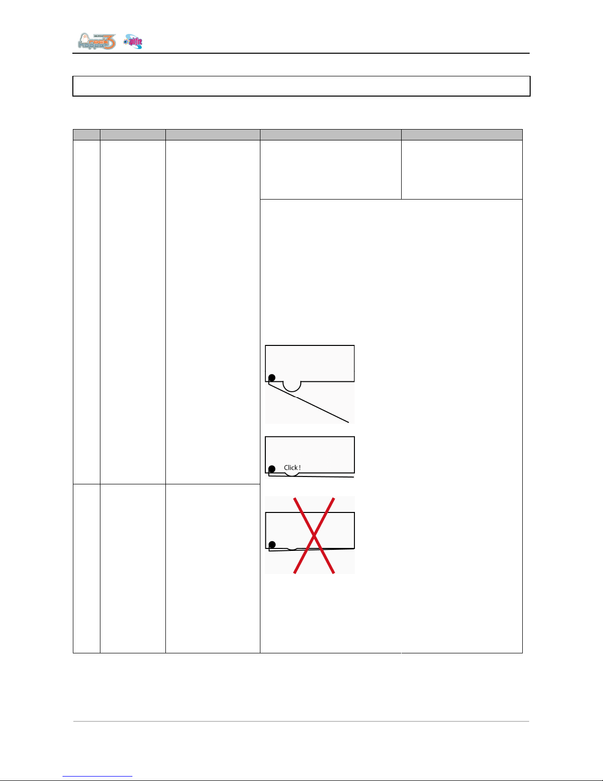
Ensure the sensor is properly
adjusted:
Adjust the sensor-bracket
or sensor-cam when
necessary
The cover-switch is a twoway switch. Or pin 1 and
2 or pin 2 and 3 are
closed.
Malfunction of the switch
might also result in the
following error:
“E068 CR Encoder Error”
Sensor state:
Pin 1 and 2 on the sensor
are closed, Pin 3 is open
(floating)
1 Cover Open The LCD indicates:
- The front cover is
open.
- One of the coverswitches is not
properly activated or
connected
Pin 2 and 3 on the sensor
are closed, Pin 1 is open
(floating)
!Attention!
Be careful when
adjusting the sensorbracket, the sensor-lip is
not fully stressed. This
will decrease life and
possibly damage the
sensor!
Adjust the sensor and
make sure there is a 0,5
to 1mm gap as
illustrated.
Page 7
Troubleshooting
7 AP-74700 – Rev. 1.0 – 10/03/2008
(3) If the cover switches are ok,
and the error persists
(4) The cover switch circuit IC’s
on the mainboard assembly
may have a problem
Verify the cover switch
connectors on the
mainboard, (J155 and
J156)
If no spare cover switches
are available, temporary
bypass on own risk is
possible, short circuiting
pins 1 and 2 for both
switches.
Replace the mainboard
assembly if after
bypassing the cover
switches, the mainboard is
still not recognizing a
closed cover switch.
(1) Try to put the lever down:
- Via the foot pedal
- Via the LCD display
If the lever is not
responding, try to short
circuit the 2 pins of the
lever foot pedal.
(2) Check the 2 sensors of the
lever UP / DOWN via
diagnostics:
Diagnostics Æ Test Æ Sensor
Æ Lever Sensor
If sensors are responding:
- Remove A heater platen.
Check if nothing is broken
in de Up/Down mechanism
- Replace the photo
sensor / sensor bracket if
the sensor is not
responding
(3) Verify if the 2 U-photo
sensors on the lever motor are
properly mounted.
• If the photo sensor is
detached or broken, fix or
replace when necessary.
(4) Check the 2 U-photo
sensors for dust or
contamination
• Clean the photo sensor
blowing compressed air
(5) Check if the sensors are
properly connected
• Check the connections
on the Mainboard assy at
connectors J123 and
J124.
2 Set Paper Indicates the lever—
sensor is in the UP
position.
The lever motor
should be the UP
position when
having this
message.
(7) If after replacement of the
sensors, the sensor still doesn’t
respond in diagnostics, the
Mainboard assembly may have
a problem.
• Replace the Mainboard
assembly.
(1) Check if both the
P_REAR_R and P_REAR_L
sensors are properly working:
Diagnostics Æ Test Æ Sensor
Æ PaperRear R and L.
When you cover the
sensor with paper, the
P_REAR sensor should
switch ON.
If the sensor is not
responding, check the
sensor alignment.
Replace if necessary.
3 Paper End There is no media
inside the printer.
The roll of media
has ended
(2) Check if the sensors are not
obstructed by dust, dirt or
media
Clean when necessary
Blow dirt and dust away
from sensor with
compressed air
Page 8
Troubleshooting
8 AP-74700 – Rev. 1.0 – 10/03/2008
(3) Check if both P_REAR
sensors are properly
connected.
Verify connections on
Mainboard assembly,
connectors J128 and
J129.
(4) The P_REAR sensor
assembly may be broken.
• Replace the P_REAR
sensor assembly.
(5) If after sensor replacement,
the problem still persists, the
Mainboard assembly may have
a problem.
• Replace the Mainboard
assembly.
1.2 MESSAGE TYPE ERRORS
Message type errors are displayed when trouble occurs during operation.
When message type errors occur, this product displays the following error messages on the operation panel
and stops the operation.
When the causes of errors are removed, message type errors are restored and the printing operation will be
restarted.
No. Message Phenomenon Check point Action Refer to
(1) Check the
operation of the
P_EDGE sensor via
“Test: Sensor” of the
self-diagnostic
function.
• If the sensor
responds to the
presence of the
paper, adjust the
sensor volume.
• If the sensor does
not respond to the
presence of the
paper, replace the
P_EDGE sensor
assembly
• Media sensor
sensitivity
adjustment
• Replacing the
P_EDGE
sensor
assembly.
(2) Make sure the
P_EDGE sensor
assembly connector
at the cursor is
securely connected.
• Securely connect
it to CR board
assembly
connector J234.
• Replacing the
Mainboard
assembly,
HDD_Extensio
n board
assembly,
HEAD_DRV
board
assembly and
cooling fan
assembly.
Undefined paper The printer failed to
detect the media.
(3) Make sure the
R_REAR sensor
assembly cables
underneath paper
guide R are securely
connected.
• Securely connect
the cables to
Mainboard
assembly
connectors J128
and J129.
• Replacing the
Mainboard
assembly,
HDD_Extensio
n board
assembly,
HEAD_DRV
board
assembly and
cooling fan
assembly.
Page 9
Troubleshooting
9 AP-74700 – Rev. 1.0 – 10/03/2008
(4) Check the
Flatcables for
skewed insertion.
• Redo the
connections of
the following
connectors :
• CR board : J201
– J216
• Mainboard : J137
– J152
• Replacing the
Mainboard
assembly,
HDD_Extensio
n board
assembly,
HEAD_DRV
board
assembly and
cooling fan
assembly.
(5) The Flatcables
from the mainboard
to the head board
may be damaged.
• Replace the
Flatcables.
• Replacing the
steel bearer,
tube guide,
Flatcable and
ink tube.
(6) The CR board
assembly may be
damaged.
• Replace the CR
board assembly.
• Replacing the
CR board
assembly.
(7) The Mainboard
assembly may be
damaged.
• Replace the
Mainboard
assembly.
• Replacing the
Mainboard
assembly,
HDD_Extensio
n board
assembly,
HEAD_DRV
board
assembly and
cooling fan
assembly.
2 Paper Slant The paper is fed
askew.
(1) Reset the paper
and check if the
condition recurs.
• If this is caused
by incorrect paper
setup, explain the
correct paper
setup procedure.
-
(1) Check the cutter
grooves for
accumulated paper
dust and slip.
• Remove the
accumulated
paper dust along
the direction of
the grooves.
• Please refer to
the User’s
Guide.
(2) Has the cutter
cap securely been
installed?
• Reset the cutter
cap securely
• Please refer to
the User’s
Guide.
(3) Check the
cutter’s up and down
sliding operation.
• If it does not rise
Go to step (4)
• If it rises : Go to
step (5)
3 Paper Cut Error Even though cutting
operation was
performed, the paper
was not completely cut
and removed.
(4) Check if the
cutter drops to the
bottom end under its
own weight when the
cutter has been
installed without the
cutter spring.
• If it drops: The
cutter spring may
have a problem.
Replace the
cutter spring while
referring to the
unfolded view.
• If it does not drop:
The cutter may
have a problem.
Replace the
cutter. If the
cutter does not
drop after
replaced, replace
the cutter holder.
→ Replacing the
cutter holder, cutter
spring, cutter cap,
solenoid assembly
and solenoid
spring.
Page 10

Troubleshooting
10 AP-74700 – Rev. 1.0 – 10/03/2008
(5) Check the up and
down operation of
the solenoid via
“Life/Cutter” of the
self-diagnostic
function.
a) The solenoid
moves up and down:
Check the cutter’s
down position
relative to the cutter
groove.
b) It does not move
up and down.
• OK: The cutter’s
service life is
reached or it is
damaged.
Replace the
cutter.
NG: Adjust the
position of the cutter
holder.
• The connectors
may have poor
contacts.
• Check the
connections of
the following
connectors :
CR board : J235
CR board : J201 –
J216
Mainboard : J137 –
J152
→ Please refer to
the User’s Guide
→ Cutter
adjustment
→ Replacing the
CR board
assembly.
→ Replacing the
Mainboard
assembly,
HDD_Extension
board assembly,
HEAD_DRV board
assembly and
cooling fan
assembly.
(6) Open CR cable,
faulty solenoid
assembly, faulty
board assembly,
etc., may be the
cause.
• Replace the
Flatcables.
• Replace the
solenoid
assembly
• Replace the CR
board assembly
• Replace the
Mainboard
assembly.
• Replacing the
steel bearer,
tube guide, CR
tapes power
cable and ink
tube.
• Replacing the
cutter holder,
cutter spring,
cutter cap,
solenoid
assembly and
solenoid spring
• Replacing the
CR board
assembly
• Replacing the
Mainboard
assembly,
HDD_Extensio
n board
assembly,
HEAD_DRV
board
assembly and
cooling fan
assembly.
4 End of Roll Displayed when the
end of the roll paper is
detected during the
use of roll paper. This
is released when the
lever has been set to
(1) Check if the
message is still
displayed after
turning the power off
and then back on
again.
If the message is
displayed : go to
step (2)
Page 11
Troubleshooting
11 AP-74700 – Rev. 1.0 – 10/03/2008
(2) Check the
P_REAR sensor
assembly for the
contact condition.
• Redo the
connections of
Mainboard
assembly
connectors J128
and J129. If the
paper is not
initialized, the
sensor may be
damaged.
• Replace the
P_REAR sensor
assembly.
→ Replacing the
Mainboard
assembly,
HDD_Extension
board assembly,
HEAD_DRV board
assembly and
cooling fan
assembly.
→ Replacing the
P_REAR_R sensor
assembly and
P_REAR_L sensor
assembly.
the up position.
(3) The Mainboard
may be damaged.
• Replace the
Mainboard
assembly.
→ Replacing the
Mainboard
assembly,
HDD_Extension
board assembly,
HEAD_DRV board
assembly and
cooling fan
assembly.
(1) Check the ink
end via “Test:
Sensor” of the selfdiagnostic function.
• Operate the lever
at the end
detecting element
of the ink sensor
assembly to
check if the ink
end indication
changes. (At this
time, the sensor
for detecting the
presence of
cartridges is set
to Yes.) If there is
no response,
replace the ink
sensor assembly.
→ Sensor menu
→ Replacing the I/H
(ink holder)
assembly
5
6
[ ] Near End
[ ] Ink End
The remaining amount
of ink is low. Printing
is still possible.
There is no more ink
left. Printing in
progress is interrupted
immediately.
(2) Check the ink
sensor connector for
the contact
conditions.
• Redo the
connections of
the following
connectors.
• Junction board :
J401 – J418
• Mainboard : J133
– J134
• Replacing the
Junction board
assembly.
(1) Check the ink
end ID via “Test:
Sensor” of the selfdiagnostic function.
(This is limited to
when smart chips
are set.)
• If the type of the
installed cartridge
does not match
the displayed
type, the ink ID
sensor may be
damaged.
• Sensor menu
7 Not Original Ink
(2) Check the ink ID
sensor connector for
the contact
conditions.
• Redo the
connections of
the following
connectors
• Junction board :
J401 – J418
• Mainboard : J133
– J134
→ Replacing the
JUNCTION board
assembly.
Page 12
Troubleshooting
12 AP-74700 – Rev. 1.0 – 10/03/2008
(3) The Mainboard
may be damaged.
• Replace the
Mainboard
assembly.
→ Replacing the
Mainboard
assembly,
HDD_Extension
board assembly,
HEAD_DRV board
assembly and
cooling fan
assembly.
(1) Check if the
message is still
displayed after
turning the power off
and then back on
again.
• When a message
is displayed : Go
to step (2)
-
(2) The amount of
waste ink inside the
tank reached the
specified level.
• Dispose of the
waste ink in the
waste bottle.
-
8 Warning Waste
INK Tank
The waste tank will
soon be full.
(3) If initialization
does take effect
when the waste ink
is disposed of and
waste ink history is
initialized, the
Mainboard may be
damaged.
• Replace the
Mainboard
assembly.
→ Replacing the
Mainboard
assembly,
HDD_Extension
board assembly,
HEAD_DRV board
assembly and
cooling fan
assembly.
(1) Check if the
message is still
displayed after
turning the power off
and then back on
again.
• When a message
is displayed : Go
to step (2)
-
(2) The number of
times the ink tube
was used reached
the maximum
allowable times.
• Replace the ink
tube.
• Initializing CR
motor history.
→ Replacing the
steel bearer, tube
guide, Flatcable
and ink tube.
9 Warning Waste
INK Tank
The service life of the
ink tube will soon be
reached.
(3) If initialization
does take effect
when the CR motor
history is initialized
after the ink tube is
replaced, the
Mainboard may be
damaged.
• Replace the
Mainboard
assembly.
→ Replacing the
Mainboard
assembly,
HDD_Extension
board assembly,
HEAD_DRV board
assembly and
cooling fan
assembly.
(1) Check if the
message is still
displayed after
turning the power off
and then back on
again.
• When a message
is displayed :
refer to step (2)
10 (Warning Head
Life)
The service life of the
print head will soon be
reached.
(2) The number of
times the print head
was used reached
the maximum
allowable times.
• Replace the print
head assembly.
• Initialize the head
unit.
→ Replacing the
print head
assembly and head
tape power cable.
→ Counter
initialization menu.
Page 13
Troubleshooting
13 AP-74700 – Rev. 1.0 – 10/03/2008
(3) If initialization
does not take effect
when the head unit is
initialized, the
Mainboard assembly
may be damaged.
• Replace the
Mainboard
assembly.
→ Replacing the
Mainboard
assembly,
HDD_Extension
board assembly,
HEAD_DRV board
assembly and
cooling fan
assembly
(1) Check the
connections of
connectors.
• Redo the
connections of
the following
connectors.
• Mainboard : J102
• power source
board (small)
assembly : CN51
– CN52
(2) The
HDD_MOTHER
board assembly may
be damaged.
• Replace the ink
tube.
• Initializing CR
motor history.
(3) Hard disk may be
damaged.
• Replace the hard
disks.
11 Hard disk status
connect error
There is a problem in
the hard disk
connections.
(4) The Mainboard
assembly may be
damaged.
• Replace the
Mainboard
assembly.
→ Replacing the
Mainboard
assembly,
HDD_Extension
board assembly,
HEAD_DRV board
assembly and
cooling fan
assembly.
→ Replacing the
power source board
assembly.
(1) The PCI_LINUX
board assembly may
be damaged.
• Replace the
PCI_LINUX board
assembly.
12 Network
initialize error
There is a problem in
the network board.
(2) The Mainboard
assembly may be
damaged.
• Replace the
Mainboard
assembly.
→ Replacing the
Mainboard
assembly,
HDD_Extension
board assembly,
HEAD_DRV board
assembly and
cooling fan
assembly.
(1) Check if the
waste bottle has
been installed.
• Install the waste
bottle correctly.
-
(2) Check the
operation of the
waste box sensor
assembly via
“Sensor/Waste Bin”
of the self-diagnostic
function.
• Replace the
waste box sensor
assembly.
-
(3) Check the
connections of the
connectors.
• Check if the
waste box sensor
connectors are
connected to the
rear side cap R.
• Redo the
connections of
the following
connectors.
• Mainboard : J120
→ Replacing the
Mainboard
assembly,
HDD_Extension
board assembly,
HEAD_DRV board
assembly and
cooling fan
assembly.
13 Waste ink tank
sts. No
The waste tank is not
installed.
(4) The Mainboard
assembly may be
damaged.
• Replace the
Mainboard
assembly.
→ Replacing the
Mainboard
assembly,
HDD_Extension
board assembly,
HEAD_DRV board
assembly and
cooling fan
assembly.
Page 14
Troubleshooting
14 AP-74700 – Rev. 1.0 – 10/03/2008
1.3 HEATING SYSTEM ERROR
Heating system errors are displayed when communication trouble occurs between the heater strips and this
product.
If heating system error occurs, the following error messages are displayed and the printer stops.
Solve the problem to delete the error message and restart the printer.
No Message Check point Action
1 AC not present AC connector. Check AC connector
2 Error sensors A Sensors A Check if the sensors are connected properly.
3 Error sensor A Sensor A Check if the sensors are connected properly.
4 Conn. err. Left A Sensor A Check if the left sensor is connected properly.
5 Conn. err. Right A Sensor A Check if the right sensor is connected properly.
6 Error sensors D1 Sensors D1 Check if the sensors are connected properly.
7 Error sensor D1 Sensor D1 Check if the sensors are connected properly.
8 Conn. err. Left D1 Sensor D1 Check if the left sensor is connected properly.
9 Conn. err. Right D1 Sensor D1 Check if the right sensor is connected properly.
10 Error sensors D2 Sensors D2 Check if the sensors are connected properly.
11 Error sensor D2 Sensor D2 Check if the sensors are connected properly.
12 Conn. err. Left D2 Sensor D2 Check if the left sensor is connected properly.
13 Conn. err. Right D2 Sensor D2 Check if the right sensor is connected properly.
14 Couldn't reach temp Heater strip After 10 minutes, temperature is not reached. Check
the heater strips.
15 Err: Temp > 85°C! Heater strip Temperature comes higher then the limit. Check the
heater strips.
16 Connection err. A Rear Heater (A) Check the connector of the rear heater.
17 Connection err. D1 Dryer (D1) Check the connector of the front heater (D1).
18 Connection err. D2 Dryer (D2) Check the connector of the front heater (D2).
19 Error sensor B1 Fixer (B1) Check the sensor of the fixer 1 (B1).
20 Error sensor C Post fixer (C) Check the sensor of the fixer (C).
21 Connection err. B1 Fixer (B1) Check the connector of the fixer 1 (B1).
22 Connection err. C Post fixer (C) Check the connector of the post fixer (c).
23 Error sensor B2 Fixer (B2) Check the sensor of the fixer 2 (B2)
24 Connection err. B2 Fixer (B2) Check the connector of the fixer 2 (B2).
25 Error D group Heaters D Temperature difference higher than 15°C between
the sensors of the D heaters.
26 Error A group Heaters A Temperature difference higher then 15°C between
the sensors of the A heaters.
27 Error B group Heaters B Temperature difference higher then 15°C between
the sensors of the B heaters.
Important
• Before checking the connectors, please power off the unit and remove the power cable.
Notes
• Check if the connectors are properly connected to the power board.
• Check if the sensors are connected onto the right connector.
Page 15

Troubleshooting
15 AP-74700 – Rev. 1.0 – 10/03/2008
1.4 DATA ERROR
Data errors are displayed when data communication trouble occurs between the computer and this product.
If data error display occurs, the following error messages are displayed and the printer stops.
Solve the problem to delete the error message and restart the printer.
No. Message Phenomenon Check point Action Refer to
1 I 15-1 error
command [ ]
Online frame error
2 I 15-2 error
command [ ]
Overrun error
3 I 15-3 error
command [ ]
Online parity error
4 I 15-4 error
command [ ]
Sum check error
5 I 15-5 error
command [ ]
ESC parameter
6 I 15-6 error
command [ ]
Undefined ESC
7 I 15-7 error
command [ ]
Incorrect letters
ESC
8 I 15-8 error
command [ ]
Numeral character
ESC
9 I 15-9 error
command [ ]
Parameter error
ESC
10 I 15-10 error
command [ ]
Buffer overflow
Check the printing
data for contents
that may be judges
as an error.
Mainboard
assembly may be
defective?
• Try a different
drive for the
application.
• Replace
Mainboard
assembly
• Replacing the
Mainboard
assembly
• HDD_Extensi
on board
assembly
• HEAD_DRV
board
assembly
• cooling fan
assembly
Notes
• The command codes for errors may be indicated between brackets [ ].
Page 16

Troubleshooting
16 AP-74700 – Rev. 1.0 – 10/03/2008
1.5 COMMAND ERRORS
Command errors are displayed when trouble occurs during analysis of the command data that is sent to this
product from the computer.
If a command error occurs, the following error messages are displayed and the printer stops.
Solve the problem to delete the error message and restart the printer.
No. Message Phenomenon Check point Action Refer to
1 MH01 error
command [ ]
Undefined ESC: A
command that has
not been defined in
command modes
was analyzed.
2 MH02 error
command [ ]
Parameter error:
Number of
parameters
following command
is incorrect.
3 MHO3 error
command [ ]
Numeric error:
Number of
parameters
following command
is incorrect.
4 MH04 error
command [ ]
Undefined letter set:
Letter sets that
should not exist (do
exist).
5 MH05 error
command [ ]
Buffer overflow:
Polygon buffer or
downloadable
character buffer
overflows.
Check the printing
data for contents
that may be judged
as an error.
The Mainboard
assembly may
have a problem.
• Try a different
drive for the
application
• Replace
Mainboard
assembly
• Replacing the
Mainboard
assembly
• HDD_Extensi
on board
assembly
• HEAD_DRV
board
assembly
• cooling fan
assembly
Notes
• The command codes for errors may be indicated between brackets [ ].
• For the settings on a computer, refer to the computer's operation manual.
Page 17

Troubleshooting
17 AP-74700 – Rev. 1.0 – 10/03/2008
2 TROUBLESHOOTING WITH ERROR
CODES
2.1 DRAM ERRORS
E001 - DRAM Error
E002 - Opt. DRAM Error
The RAM memory module is not or badly recognised on the mainboard.
• Be sure RAM memory contacts are clean
• Make sure you us an Original Mutoh Memory Module ONLY.
• 3
rd
party memory-modules will not work properly. Never use these!
Page 18

Troubleshooting
18 AP-74700 – Rev. 1.0 – 10/03/2008
2.2 CPU ERRORS
These errors can appear when internally the machine detected an illegal software command in the central
microprocessor-circuitry inside the mainboard.
This can happen due to:
• Illegal header-commands might be sent from the rip-computer Æ Make sure the rip is always updated to
the latest version!
Also make sure the latest printer-driver from the Mutoh-website!
If the problem is still occurring:
o Try another rip computer or use a pre-ripped (demo-) file provided by Mutoh.
o Try to rip to a different (analog) Mutoh-printer, whenever available.
o Try to rip an internal job, e.g. print a palette or distance adjust test
• A power drop or spike on the power supply Æ Reboot machine
Check if the problem reoccurs. Also always check for a good, stable power connection + properly
grounded.
• Generally when a permanent-occurring CPU-error appears on your LCD display, every time after
restarting the machine several times, there are possible clues:
• Install always the latest and correct firmware-version!
SX for new-generation RoHS-compliant mainboards
SP for the previous non-RoHS-compliant mainboards
o The onboard offline-memory may be corrupt. Reset the NVRAM and re-insert all the parameters
manually (not with a backup-flashcard or via Ethernet) via the LCD Display. Manual input avoids
copying corrupted data back.
o With the installed firmware – Always install the correct and the latest firmware version!
o Try with a different Mutoh memory-module.
o If this error still reoccurs after these actions, replacing the mainboard and re-inserting the parameters
manually is the last solution. Same reason again, why inserting parameters manually, is to avoid
copying possible NVRAM data to the new mainboard.
• For printers equipped with an older non-RoHs mainboard can, you can also try the following procedure:
o Load the Falcon II v1.26 firmware
o Load directly afterwards, back the latest firmware applicable for your machine
o Re-insert the parameters via the LCD display (to avoid copying corrupt parameters)
o Test if the machine is working properly and try to print
o If the problem still persists after this, the mainboard might need to be replaced
• For printer equipped with a RoHs-mainboard (Revision A or later), this described test is not applicable as
no Falcon II machines exist with these boards. So just make sure you use the latest firmware-version!
Some more specific CPU errors:
2.2.1 E 016 error CPU Err(03)
Data boundary exception errors. Trouble occurred in the data boundary in its internal memory.
• Make sure you us an Original Mutoh Memory Module ONLY.
• 3
rd
party memory-modules will not work reliably!
Page 19

Troubleshooting
19 AP-74700 – Rev. 1.0 – 10/03/2008
2.3 PF - PAPER FEED ERRORS
¾ E065 - PF Motor Err
¾ E067 - PF Encoder Err
¾ E069 - PF Timeout Err
¾ E071 - PF OverCurrent
¾ E083 - PF2 OverCurrent
The Paper-Feed motor is failing or the electronics doesn’t receive an encoder-signal from the PF sensor
correctly.
The electronics wants to move the Paper Feed system (PF). The driver IC on the mainboard provides power
to the X-motor (1). Therefore the X-motor starts to turn, resulting in a PF movement (2). PF movement is
detected via the encoder-sensor (3), and gives feedback, back to the electronics.
This closed-loop system is fully controlled in the electronic circuit of the mainboard. It regulates the direction,
electrical current and the speed of the carriage extremely precisely.
Mainboard
PF-X-motor
X-Encoder
Forward movement
Grid Roller
Backward movement
Grid Roller
PF Encoder Disk
2
1
3
Step 1 : Power supply to motor from electronics
Step 2 : Mechanical movement X encoder
Step 3 : X encoder gives feedback to mainboard
Page 20

Troubleshooting
20 AP-74700 – Rev. 1.0 – 10/03/2008
If anything goes wrong in this process, the following parts inside this loop needs to be verified:
1)
Verify the encoder signal of the Paper Feed system
Diagnostic Æ test Æ encoder Æ PF
If the Hex counter changes near PF, when turning the grid-roll shaft, the encoder is ok.
If not ok:
• Be assured that the PF encoder sensor is properly adjusted and positioned
• Check if the encoder disk is clean and not scratched. Clean with Isopropyl alcohol and a fibre-free
tissue only!
Verify the X-motor functionality via the aging procedure
Diagnostics Æ Life Æ PF Motor
If the motor is not responding:
• Go to step 3, verify the driver + cable connections
• If still not OK, replace the X-motor
2) Check the X motor driver-IC.
The driver chip is located on the mainboard on U94 for old board revisions. New board
revisions (RoHS) the driver chip is the U109. The following pins should be measured:
• Between pin 1 and 10
•
Between pin 2 and 11
The measurement value should be approx. 2 to 3 Meg Ohms. If this is not the case, the driver is broken,
replace the mainboard
Page 21

Troubleshooting
21 AP-74700 – Rev. 1.0 – 10/03/2008
2.4 CARRIAGE RELATED ERRORS
2.4.1 E066 - CR Motor Err
2.4.2 E068 - CR Encoder Err
2.4.3 E072
- CR OverCurrent
The mainboard is not receiving an encoder-signal, from the CR encoder sensor. Even though, the
mainboard sends a signal to the CR-motor to move the carriage.
Basic principles of the CR-Driving and Encoder-system:
Mainboard
Y-motor
Y-Encoder
CW-Movement
= Carriage moves left
CCW-Movement
= Carriage moves right
1
2
3
Step 1 : Power supply to motor
Step 2 : Mechanical movement moves Y encoder
Step 3 : Y encoder gives feedback to the mainboard
The electronics wants to move the carriage. The driver IC on the mainboard provides power to the Y-motor
(1). Therefore the Y-motor starts to turn, resulting in carriage-movement (2). Carriage movement is
detected via the encoder-sensor (3), back to the electronics.
This closed-loop system is fully controlled in the electronic circuit of the mainboard. It regulates the direction,
electrical current and the speed of the carriage extremely precisely.
Page 22

Troubleshooting
22 AP-74700 – Rev. 1.0 – 10/03/2008
If anything goes wrong in this process, the following parts inside this loop needs to be verified:
1) Check the encoder sensor
Go to diagnostics Æ test Æ encoder
If the Hex counter changes near CR_ENC, when moving the carriage, the encoder signal is OK. To be able
to move the carriage freely, the front cover (incl. cover sensors) must be opened.
2) Check the cover switches + connectors
The cover switches make contact with a relay. This relay physically connects/disconnect the Y-motor from
the Y-motor power circuitry. Pin 1 and 2 will measure 0 ohms.
If one of both cover switches are open, the relay will disconnect. Instead the cover switch must close
contacts 2 and 3. In this way the /COVER-detection lines integrated inside the electronics, will recognise
that the cover is open and inform the operator.
• Check if the connector J156 is bridged
between pin 1 and 2 on the mainboard
(applicable for SPFR100 only)
• Make sure J155 is properly connected to
the cover switch
Important
• 28 Volts is directly connected to the cover switches! Therefore the switches are properly
insulated. Be aware removing the covers, the chassis is not touching the insulation and
breaking so it hits the contacts. This will result in a broken main board!
• Shutting-down the printer while removing the covers is strongly recommended!
The sensor can also be checked via the “test sensor” inside diagnostics.
3) Check the relay RY1 on the mainboard
On the picture, you can see that the relay can switch the Y motor on/off. If the cover is being closed (= both
switches closes too), you should hear the relay clicking.
If the relay RY1 is NOT clicking after closing, verify if the cover switch is really closed. Measure pin 1 and 2
of the connector of J155 and J156. Both pins should be 0 ohms!
If the switches are OK, the relay or the driver of the relay on the mainboard might be is broken. In that case
replace the mainboard
Page 23

Troubleshooting
23 AP-74700 – Rev. 1.0 – 10/03/2008
4) Check the Y motor driver-IC.
The driver chip is located on the mainboard on U97 for old board revisions. New board revisions (RoHS) the
driver chip is the U112. The following pins should be measured:
• Between pin 1 and 10
• Between pin 2 and 11
The measurement value should be approx. 2 to 4 Meg Ohms.
If this is not the case, the driver is broken, replace the mainboard
5) Verify the Y-motor, make sure the carriage is running smoothly and the motor makes no noise.
Make endurance tests via: Diagnostics Æ Life Æ PF Motor
If the motor is not responding:
• Go to step 4, verify the driver + cable connections (white cable is +, black cable is -)
• If still not OK, replace the X-motor
6) Check the steel belt pressure. A wrong steel belt pressure will result in frictioning. Therefore the
“controlled loop feedback”-system will fail.
Blizzard 65” = 1 Newton (100 gr) – Blizzard 90” = 0,9 Newton (90 gr)
If you are sure all previous parts are ok, check the steel belt pressure; check the ‘smoothness’ of the
carriage. Verify the Y-motor and if necessary, replace it.
Verify if the Y-motor belt. Same reason as for the steel belt.
• Verify if the belt is in good shape and properly greased
• Verify the belt’s pressure Æ 35 Newton (3,5 kg)
Verify the carriage movement. The carriage should run smoothly over the whole length.
• The carriage should also run smoothly without steel belt. If not check the carriage-bearings.
• Both steel-belt pulleys should run smoothly
2.4.4 E070 - CR Timeout Error
This error occurs when the carriage didn’t move to the expected, correct position within a certain amount of
time.
1) Verify the Carriage movement with aging tests
Diagnostics Æ Life Æ CR motor
2) Verify the linear encoder strip. Clean the encoder strip with Isopropyl Alcohol if necessary.
Check if the encoder strip isn’t scratched.
3) Verify the encoder sensor
Diagnostics Æ Sensor Æ encoder Æ CR
Move the carriage and check if the HEX-counter on the LCD-display is going up and down over the
complete length of the Y-rail.
Page 24

Troubleshooting
24 AP-74700 – Rev. 1.0 – 10/03/2008
2.4.5 E073 - CR Origin Error
The origin sensor of the printer Carriage cannot be detected.
Step 1 : Verify the U-pot sensor on top of the Y-rail Check if the U-photo sensor is properly aligned and
the carriage-flag activates it. The U-sensor can be tested by putting some non-transparent
material inside to activate.
Diagnostics Æ Test Æ Sensor Æ CR Home position
Step 2 : Verify cable connections on sensor and mainboard
Step 3 : If sensor is not responding, replace sensor + verify, eventually replace cabling
Step 4 : If still no response after sensor replacement, the mainboard might be defect (replace mainboard)
2.4.6 E074 - Cover Sensor Error
Step 1 : Verify all cover sensors as described in error E068.
Step 2 : Verify cover sensors in Diagnostics Æ Test Æ Sensor Æ Cover switches
Step 3 : Verify if the front cover is closing all the switches properly
Step 4 : Verify sensor cable connections, try to bypass sensors by short-circuiting pins 1 and 2
Step 5 : If still not ok, replace mainboard + cover switches
2.4.7 E076 - PG Origin Err
Step 1 : Verify if the optical sensor is working by putting something a piece of material before it. The
sensor can be tested via:
Diagnostic Æ sensor Æ HD_SLIDE sensor
Step 2 : The optical headheight home-sensor (HD_SLIDE) can not be detected.
Apply some non-reflective and non-transparent black tape on the right carriage headheight
adjustment-bracket. This will improve the performance of the optical sensor (which only detects
black/white transitions) to detect the hole in the adjustment-wheel of the headheight assembly.
Step 3 : Verify the headheight homing sensor and the Up-Down motor via:
Diagnostics Æ Life Æ Head U/D
Step 4 : If the motor is not running, replace the motor
Step 5 : If still not ok, verify cable connections.
Step 6 : If all previous steps did not help you any further and a replacement sensor also doesn’t give any
response, only then replace the mainboard.
Page 25

Troubleshooting
25 AP-74700 – Rev. 1.0 – 10/03/2008
2.4.8 E078 - Head Cable Error
The flatcable of head number 1 is not properly connected. This is applicable on as well 4 as 8 heads
machines.
Head 1 MUST always be connected, as the head contains a temperature probe. The machine will always try
to retrieve the temperature during start-up. If you get this error, it indicates, a flatcable is not connected
properly. Verify all flatcable connections. Please refer to flatcable treatment.
In future firmware releases, this error can as well be a fatal error or a non-fatal error (warning message).
Please check the flatcable-treatment chapter for more information how to solve the problem.
Page 26

Troubleshooting
26 AP-74700 – Rev. 1.0 – 10/03/2008
2.5 LEVER & PRESSURE ROLLER ERRORS
2.5.1 E079 - Lever OverCurrent
Step 1 : The lever motor is drawing too much power. Replace the lever motor.
Step 2 : Verify for any short circuits in the motor wiring between the motor and the mainboard.
Step 3 : Check the Y motor driver-IC.
The driver chip is located on the mainboard on Uxx for old board revisions. New board revisions
(RoHS) the driver chip is the Uxxx.
The following pins should be measured:
• Between pin 1 and 10
• Between pin 2 and 11
The measurement value should be approx. 2 to 3 Meg Ohms.
If this is not the case, the driver is broken, replace the mainboard
2.5.2 E080 - Lever Sensor Err
The lever up / down sensor of the lever motor did not respond within a certain time or the Up-Down sensor is
failing.
Step 1 : Verify the Up / Down sensors
Diagnostics Æ Test Æ Sensor Æ Lever Up / Down
• Verify if both sensors are clean
• Verify the cable connections on the sensors and the mainboard
Step 2 : Verify if the gear-wheel / sensor flag of the pinch rollers is properly activating both sensors
Step 3 : Verify if the lever-motor is working and properly geared. Therefore you need to remove the A-
heater platen to be able to verify this.
Step 4 : Check the Y motor driver-IC.
The driver chip is located on the mainboard on U109 for old board revisions. New board revisions
(RoHS) the driver chip is the U123.
The following pins should be measured:
• Between pin 1 and 10
• Between pin 2 and 11
The measurement value should be approx. 2 to 3 Meg Ohms.
If this is not the case, the driver is broken, replace the mainboard
Page 27

Troubleshooting
27 AP-74700 – Rev. 1.0 – 10/03/2008
2.6 CAPPING STATION ERRORS
2.6.1 E081 - Cap Sensor Err
The cap sensor detects if the capping station-assy is in the downward position. It’s a photo sensor that is
fixed inside the capping-station.
2.6.2 Sensor diagnostics
Step 1 : Verify if the sensor is working properly. Insert a non-transparent piece of material inside the
optical U-sensor to activate the sensor. The default value is OFF and should switch ON.
Menu location:
Start up in diagnostics – Test – Sensor – Cap
Step 2 : Push the capping station down and turn the stepper motor to keep it down. Check if the Cap-
sensor goes into the U-sensor properly + verify in sensor diagnostics (see previous step)
Step 3 : Verify if the sensor is properly mounted on the capping-station assembly.
Step 4 : Verify if the optical U-sensor is clean and not covered with ink or contamination
Step 5 : Check the U-sensor cable connection on the sensor and the mainboard
2.6.3 Capping - Motor diagnostics
Step 1 : Verify if the Capping stepper motor is working properly in diagnostics
Motor functionality can be verified multiple times with the Ageing menu.
Menu location:
Start up in diagnostics – Test – Life – Head Lock – Select Wiper U/D off
Step 2 : If the stepper motor is not working properly or loosing torque, verify if the gears and plastic parts
are properly lubricated/greased.
Step 3 : If the stepper motor is not responding at all:
• Verify the stepper motor, replace if necessary
• Replace the mainboard
2.6.4 E082 - Wiper Sensor Err
The wiper sensor, located below the wiper assembly was not activated when the heads were being wiped.
Page 28

Troubleshooting
28 AP-74700 – Rev. 1.0 – 10/03/2008
2.6.5 Sensor diagnostics
Step 1 : Verify if the sensor is working properly. Unlock the carriage from the capping station, using the
Head Unlock in Diagnostics. Move the head on the side. Remove the wiper plate assembly.
Insert a non-transparent piece of material inside the optical U-sensor to activate the sensor. The
default value is OFF and should switch ON.
Menu location:
Start up in diagnostics – Test – Sensor – Wiper
Step 2 : Mount the wiper plate assembly back on the capping station. Move the wiper assy to the outer
position to activate the U-sensor. Check if the Cap-sensor goes into the U-sensor properly and if
the value on the display switches ON and OFF.
Step 3 : Verify if the sensor is properly mounted on the capping-station assembly.
Verify if the sensor-flag properly activates the sensor, check if the flag goes deep enough inside
the sensor.
Step 4 : Verify if the optical U-sensor is clean and not covered with ink or contamination
Step 5 : Check the U-sensor cable connection on the sensor and the mainboard.
2.6.6 Wiper - Motor diagnostics
Step 1 : Verify if the Capping stepper motor is working properly in diagnostics
Motor-functionality can be verified multiple times with the Ageing menu.
Menu location:
Start up in diagnostics – Test – Life – Head Lock – Select Wiper U/D on
Step 2 : If the stepper motor is not working properly or loosing torque, verify if the gears and plastic parts
are properly lubricated/greased.
Step 3 : If the stepper motor is not responding at all:
• Verify the stepper motor, replace if necessary
• Replace the mainboard
Page 29

Troubleshooting
29 AP-74700 – Rev. 1.0 – 10/03/2008
2.6.7 E097 - NVRAM Error
Diagnostics Æ Test Æ NVRAM
Free space: bytes free
Max block: largest block free (bytes)
If an error occurs, problems occur or the free space for parameters is very low (<100) try the following:
Diagnostics – MOD Level – Reset to 0, reboot the machine and wait until completed.
Then repeat the diagnostics. If still not ok, clear NVRAM, reboot.
If the test is still failing Æ Replace mainboard
E100 - 28V P. Supply Err
E101 - 42V P. Supply Err
The machine is not detecting 28 or 48 Volts from the power supply.
Possible reasons:
• Bad contact power connectors
• Short circuit somewhere inside the machine
1) Try to disconnect all possible boards (network card, slave boards, print heads, etc.) to exclude
any shortcircuits. It works; reconnect every board step-by-step to find the possible cause.
Pin out to measure the main power supply connected to J101 on the mainboard:
Pin out of the supplemental 12V power supply connected to J102 on the mainboard:
Pin 1 & 2 = 12V
Pin 5 & 6 = GND
Pin 4 = Power On
Pin 5 = 5V
Remark: The machine contains a switching power supply and must always be measured when it is under
load. (This means: connected on the mainboard)
Page 30

Troubleshooting
30 AP-74700 – Rev. 1.0 – 10/03/2008
2.7 HEAD AND FLATCABLE RELATED ERRORS
E102 - Fuse 1 Error
E103 - Fuse 2 Error
E104 - Fuse 3 Error
E105 - Fuse 4 Error
E106 - Fuse 5 Error
E107 - Fuse 6 Error
E108 - Fuse 7 Error
E109 - Fuse 8 Error
E077 - Head OverHeat (Somewhere between head 1 and 8)
Æ Applicable on old mainboards (< Rev. W) only
E110 - Head Overheat 1
E111 - Head Overheat 2
E112 -Head Overheat 3
E113 - Head Overheat 4
E114 -Head Overheat 5
E115 - Head Overheat 6
E116 - Head Overheat 7
E117 - Head Overheat 8
The fuses protect the electronic driver components on the mainboard. Every ink-channel has a separate
fuse, so every printhead have 2 fuses, located on the main board below the Head Driver Board.
Old revision mainboards need some soldering, to remove the old fuse and to put a new one.
New revision boards (RoHS) do not need soldering. The fuse can easily be replaced as it is socketed.
Important
• ONLY USE THE FUSE DEFINED IN THE SPAREPARTS FROM MUTOH. DO NOT USE ANY OTHER FUSE AS WE
CANNOT GUARANTEE THE CORRECT TYPE USED
.
• P
LEASE REFER TO TIB 188 FOR MORE INFORMATION
Page 31

Troubleshooting
31 AP-74700 – Rev. 1.0 – 10/03/2008
2.8 ETHERNET CARD ERRORS
E128 – ONLINE Error
E129 – EthROM error
E130 – EthRAM error
E131 – EthBank RAM error
E132 – EthNIC chip error
E133 – EthLback error
The Ethernet card is failing Æ Replace Ethernet card
2.9 MAINBOARD RELATED ERRORS
2.9.1 E211 – Incompatible hardware
Recent firmwares are always compatible with all mainboard-revisions.
• Always use the correct firmware version for the correct hardware:
o Non-Rohs mainboards have the extension SP (e.g. 3.00sp)
o Rohs-compliant mainboards have the extension SX (e.g. 3.00sx)
• Always use the latest firmware-version. Older firmware-versions might possibly not compatible
with newer hardware.
2.9.2 E256 – Mode not found
Problems related to the SIMM card or wallet system.
• Check the specific error-number via diagnostics mode > Chipmgr
• Proceed to the SIMM-Card diagnostics chapter
2.9.3 E257 – Mode not available
Invalid machine settings
Contact the Mutoh service department
2.9.4 E258 – Mode Init problem
Contact the Mutoh service department.
Page 32

Troubleshooting
32 AP-74700 – Rev. 1.0 – 10/03/2008
2.9.5 A259 – Hardware not found
This is a smart-chip, wallet or CLIB-related problem, including flatcable connection to the mainboard. As this
can be a very complicated problem, the analysis needs to be followed step-by-step.
2 possibilities:
• One smart-chip inside the cartridge-reader, is interfering the cartridge-smartchips or the internal wallet-
SIMM card. All the smart-chips are connected to 1 serial bus. This communication-bus can be
disturbed, preventing some of all smart chips and the wallet, to be ‘read’.
• The simm card or simm card reader is not available or defect. Verify if:
o The Card-reader is properly connected
o The SIMM-card is inserted in it’s socket properly
o The CLIB board is not properly properly functioning or badly connected
Verify flatcable connections thoroughly!
Step 1 : Verify if the SIMM card and the SIMM card reader is functional:
• Remove all the cartridges that has a smart-chip.
• Reboot the machine, go to diagnostics mode > Chipmgr
• Verify the chip-status. If the SIMM-chip is ok, go to step 2.
• If the SIMM card is NOT ok:
o And taking into account, all the cartridges have been removed, following parts
can be faulty:
¾ The SIMM chip is broken, proceed to the service-chip procedure. Check
the specific error-number via diagnostics mode > Chipmgr
¾ The CLIB board is improperly connected to the Mainboard. Try to swap
the 2 flatcables on both sides, to see if the problem ‘shifts’ to other
cartridges or becomes OK.
Step 2 : Go to user-mode, menu “Ink Status”, verify ink status of all cartridge-smartchips separately
• Insert every cartridge one-by-one
• Verify with each inserted cartridge, if the smartchip is properly recognised. Cartridges with non-
readable smartchips should be reinserted several times to be sure it’s not bad contact. Check the
smart-chip issues documentation.
If the smartchip remains unreadable, try another analog cartridge or swap cartridges located on
another location inside the cartridge-station. Check if the smartchip can be ‘read’ on this other
location. If still not ok, the chip might be defect.
• Verify the 2 flatcables if they are properly connected, swap the 2 flatcables to verify if the problem
‘shifts’ to another location.
Step 3 : If cartridge smartchips and wallet can ALL properly be read and the same problem still re-occurs
after rebooting:
• Remove all the cartridges again
• Insert all cartridges one by one, for each inserted cartridge, reboot again. Where the problem
possibly reoccurs, remove the cartridge. Retry with another cartridge. If still not ok:
o The CLIB board might be improperly connected to the Mainboard via the 2
flatcables.
o Try to swap the 2 flatcables on both sides, to see if the problem ‘shifts’ to other
cartridges or another problem appears.
Page 33

Troubleshooting
33 AP-74700 – Rev. 1.0 – 10/03/2008
2.9.6 E260 – Incompatible Firmware
Check and make sure that the correct firmware is installed on the correct machine, eg. Spitfire firmware on
Spitfire machine. Blizzard firmware on the blizzard, etc.
2.9.7 E261 – Firmware Init Problem
Contact the Mutoh service department.
2.10 WALLET-SIMM-CARD ERRORS
Wallet-SIMM errors can be analysed inside the diagnostics-menu:
ChipMgr -> Status
In normal circumstances the chip should indicate, everything is ok and the amount of ml should be visible.
Possible status information when the chip might have a problem:
[E1] Printer chip is broken Æ Install a service chip
[E2] Printer chip is broken Æ Install a service chip
[E10] Invalid chip Æ Install a service chip
[E32] Invalid chip operation occurred Æ Restart machine
Other errors:
[E….] Chip all chip connections
SIMM-card errors can be due to the Wallet-SIMM card, mounted inside the machine.
However, problems might also occur due to the printer cartdridges (e.g. “Not Original Ink”). In fact, in this
case it’s the smart-chips that might be causing this issue. The internal SIMM and the smart-chip
management system (8 smartchip-cartridge-readers) are al interconnected. One chip can interfere with the
others and potentially give an error.
So when you know, cartridges with smart-chips are inside the machine and an [Exx]-error occurs, the error
can be caused by 2 possible reasons:
• The internal SIMM Card
• One of the 8 cartridges with smart-chips
Page 34

Troubleshooting
34 AP-74700 – Rev. 1.0 – 10/03/2008
To make an accurate diagnose of the problem, execute the following steps:
Step 1 : Shutdown the machine and remove all cartridges with smartchips
Step 2 : Check flatcables between mainboard and cassette led interface board (CLIB)
Step 3 : Check all connections on the CLIB board
Step 4 : Check all connections on SIMM-wallet PCB
Step 5 : Check all connections on the CLIB expander board (SPFR100 only)
Step 6 : Restart the machine without any cartridges, verify if the error still occurs Æ if not, check TIB252
Step 7 : If the error doesn’t occur, insert every cartridge back one-by-one and verify if every cartridge is
properly recognised in “ink status”
Step 8 : If non of above helps, install a service chip
Step 9 : Follow the service chip activation procedure
In the case, that cassette-smart-chips are responsible for causing an [Exx]-error, you can try the following
topics:
• If the internal wallet is used, the smart-chips on the cartridges can be removed. The credits can be
downloaded inside the printer. Beware that there is no glue or self-adhesive remaining on the smart-chip
or cartridge. This to avoid contamination of the smart-chip reader!
o Ink end will always be detected as this is a physical switch detection
o Ink levels per cartridge will not be readable when using the internal wallet. Only the total ink amount
charged inside the wallet, will be readable.
• If smart-chips are used, follow the TIB252, flowchart “not original ink”.
Page 35

Troubleshooting
35 AP-74700 – Rev. 1.0 – 10/03/2008
3 TROUBLESHOOTING WITHOUT ERROR
CODE
3.1 PARAMETER & PRINTING RELATED ISSUES
3.1.1 Parameters are not being saved during shutdown
Step 1 : Be assured to use the latest firmware-version
Step 2 : Check available NVRAM
Diagnostics Æ Test Æ NVRAM
Free space: bytes free
Max block: largest block free (bytes)
If an error occurs, problems occur or the free space for parameters is very low (<100), proceed
to the next step
Step 3 : Go to diagnostics – and change MOD-level to 0
(MOD-level defragments internal parameters, clearing memory for additional data, can be reverified with Test Æ NVRAM)
Step 4 : If still not ok:
a. Try to reset the parameters
b. Try to clear the NVRAM
Step 5 : If the problem still persists, the NVRAM might be damaged Æ replace mainboard
3.1.2 Unstable machine behaviour (CPU errors, machine crashes)
If this behaviour still proceeds, after replacing a main-board and restoring the parameter-backup, in some
rare cases, it can happen that something inside the parameters becomes corrupt but we cannot see. This
results mostly in strange machine-behaviour (unknown cpu errors, crashes).
Æ In that case a parameter backup should not be taken because when you restore it, you might literally
‘restore the problem’ on another board.
In this situation, the clearance of the NVRAM may be proceeded.
Before proceeding to this try to print out the machine setup and parameters to insert everything with the
same values afterwards.
Important
• BEFORE PROCEEDING WITH THIS PROCEDURE, ALWAYS USE THE LATEST FIRMWARE VERSION. IF THIS IS NOT
DONE
, YOU MIGHT LOOSE THE SETTINGS AND WILL MAKE YOUR MACHINE TOTALLY UNUSABLE. IN THIS CASE
MAINBOARD REPLACEMENT IS THE ONLY OPTION
.
This procedure takes much more time and is more complicated (the machine doesn’t know if there is ink
inside, eco ink or mid solvent ink, or cleaning, the serial number is gone, head adjustments in parameters
must be re-programmed, distance adjust, etc…). This manual programming, will take much more labourtime… (up to a few hours)
So, in this situation, manual parameter might anyway still be useful…
Page 36

Troubleshooting
36 AP-74700 – Rev. 1.0 – 10/03/2008
3.1.3 Printer doesn’t start printing, interrupts or intermittently stops
during
printing
Step 1 : Try to launch an internal printer test, e.g.
Testprint – Palette
Æ If this is working, proceed to the next point
Step 2 : Verify network connections
• Verify if the IP-address is ok on Machine, computer and Rip-software
• Check if you can ping the IP-address from the computer command window
• Assure that the IP-address is set-up properly according to ‘normal circumstances’. Make a
testconnection by configuring both devices into a mini-class C-network (192.168.x.x subnet
255.255.0.0)
• Disable any computer-firewalls as they might block, interrupt or slow down the printer
• Make sure the network-cabling is ok, always respect the following guidelines:
o Only use stranded UTP-cables, stranded cables have a very high flexibility because it has
multiple copper fibres per cable when for connecting printers to wall sockets, computers,
switches and mounting onto RJ45 connectors.
o Rigid UTP-cables have 1 thick copper core per curve and are designed for fixed wall-mounting
and inside sockets only and are NOT suitable as patchcables
! Never use that kind of cables,
between the printer and a computer or wall-socket! Mounting RJ45 connectors on that kind of
cables will guarantee bad contacts with signal-quality loss, network problems resulting in printing
problems.
o Make a direct connection between rip-computer and printer with a cross-cable. This ensures
maximum data-transfer without network-interference.
o The newest generation printers require high quality cables. Thus Cat 5E cables are suitable for
Gigabit networking, however CAT6 cables are strongly recommended for optimum signal-quality!
Step 3 : Try to connect to another computer, try to print with a pre-ripped file (e.g. Mutoh adjustment-files)
Step 4 : If still not ok, replace the Network-card and try again
Step 5 : If still identical, replace the mainboard and try again
Page 37

Troubleshooting
37 AP-74700 – Rev. 1.0 – 10/03/2008
3.1.4 Ink drops falling on media from heads during printing
Step 1 : Never remove cartridges out of the printer when it’s uncapped!
If cartridges are removed when the machine is not on it’s capping station, ink will leak out from
heads and air will be sucked through the cartridge-needle.
Step 2 : Once air-bubbles inside the tubing, the risk of smudging and destroying the print is possible!
Step 3 : To solve: proceed with ink load to remove all ink-bubbles from the tubing
Inkmanager Æ Ink load
Step 4 : Avoid dust particles below the printer heads by any means. 1 piece of dust on the nozzle-plate
will suck out ink from the heads resulting in ink drops.
Avoid placing the printer in dirty and dusty environments. Clean the machine on a regular basis.
Step 5 : Verify if wipers are in good shape. After wipe action, before printing, verify if the nozzle-plate
around the nozzles, is 100% clean. If not, clean the wipers. If the wipers are not straight
anymore, replace wipers.
Step 6 : The printer is a high-precision instrument that needs care and maintenance, this due to the
nature of the solvent inks.
Be sure to respect the recommended daily maintenance procedures according to the ink used, to
assure optimum performance.
Step 7 : Respect the environmental conditions as described in the installation guide. During winter-time
and cold periods, low environmental humidity will decrease print performance.
Step 8 : Place the machine in an antistatic location. Antistatic flooring is recommended.
Step 9 : All electronical equipment (printer + computer) must be properly earthed.
Step 10 : Very Low environmental humidity also causes plastic materials like banner and vinyl’s to charge
statically. Statically charged materials might cause printing anomalies like:
• Ink drops
• Nozzle inaccuracy and deflection
• Bad printing quality
Step 11 : Printing materials need to be climatized in the same environment as the printer for at least 8
hours, before being ready for printing.
Step 12 : Always use the latest released Firmware version.
Page 38

Troubleshooting
38 AP-74700 – Rev. 1.0 – 10/03/2008
3.2 PRINTING RELATED PROBLEMS
3.2.1 Complete nozzle-row (A or B-channel) is missing
Step 1 : Try if you can recover, performing a cleaning (powerful)
Step 2 : If nozzles still do NOT appear after a cleaning, try to connect a seringe and suck with the
seringe instead, be assured that the seringe is making a proper vacuum.
If a vacuum cannot be created with the seringe, verify:
• If the damper is properly connected to the head’s nipple
• If the damper is intact and the membrane is not punctured
• If the ink-tubing is properly connected from cartridge up to damper. Make sure there is an air-tight
connection between every tube and O-ring.
• If the ink-cartridge is not empty (..and the empty-flag is not being detected properly)
• If the nipple of the printing head is not leaking or broken-off
If a vacuum can be created with the seringe, verify:
• If flatcables are properly connected to the head
• If the fuse on the mainboard is still intact
• If the nozzle-row or the damper is not blocked / dried out
Page 39

Troubleshooting
39 AP-74700 – Rev. 1.0 – 10/03/2008
3.2.2 Head is firing continuously
With continuous firing we define the following:
One head or one colour-channel is firing continuously over the whole print-length, over the whole length of
the movement of the carriage, as well over the edge of the media, as on the print platform.
In this situation, firing will occur starting from the flushing-box, over the print platform and over the edge of
the media up till where the carriage stops.
First of all, be assured, the latest firmware-version is installed in the machine!
This can also give an indication, that there might be problems with the fuse of this head- or colour-channel.
Possible indications are (in order of most to less important reason):
• Short flatcables badly connected
• Long flatcables badly connected
• HEAD_DRV board
• Mainboard (mainly checking and/or replacing fuses)
• Print head itself
When that kind of problem is reported it’s always recommended to have at least these spares available for
replacement.
To solve this problem, following the instructions described in TIB188 (Flat Cable Treatment) is strongly
recommended! Flatcables must be in perfect condition
and must be connected 100% perfectly!
Notes
• Fuses on the mainboard can be easily measured with an Ohm-meter. A fuse in good
condition, should have approx 0 Ohms resistance. Fuses on non-RoHS mainboards must be
re-soldered with a new one, when broken. Fuses on a RoHS mainboard, can easily be
replaced with a tweezer.
Important
• When replacing fuses, always remove the power-cord and discharge the machine, to
avoid static charge and damage to electronics!
Page 40

Troubleshooting
40 AP-74700 – Rev. 1.0 – 10/03/2008
3.3 INITIAL MACHINE STARTUP-RELATED PROBLEMS
A simplified, automatic procedure for loading the appropriate cleanings and inks has been developed and is
executed via firmware.
This makes it easier for the customer to load the correct liquids inside the printer. The big advantage of the
smart-chip management system is that it can identify, if the correct cartridge inserted. It also assures that
the correct procedure is followed like described in the user’s manual. So there is a double security!
This procedure is of utmost importance as not all solutions and inks are directly compatible. If notcompatible solutions and inks are mixed, the heads and ink tubings inside the printer might block resulting in
replacement and a lot of work.
3.3.1 Ink and cleaning compatibility-Chart
Water-based solution STL-Liquid (Eco Solvent Cleaning) ECO Solvent Ink
Water-based
solution
Compatible Compatible
NOT Compatible
STL-Liquid (Eco
Solvent CLN)
Compatible Compatible Compatible
Mild Solvent
Cleaning
NOT Compatible
Compatible
NOT Compatible
Mild Solvent Ink
NOT Compatible NOT Compatible NOT Compatible
As you can see in the chart, ECO-Solvent Inks, are also NOT compatible with either water-based, either,
Mild solvent Cleanings or Ink. So avoid the mixture of these solutions in any case inside the machine’
tubings and heads!
Brand-new machines are shipped are standard delivered with a water-based solution:
• Inside the ink-tubings
• Inside the dampers
• Inside the heads
The chart shows that water-based solution and solvent inks are NOT compatible!
When Solvent inks are mixed with water-based solution, the pigments of the ink will decay and it will block:
• The ink tubings
• The dampers
• The heads
To avoid this, multiple cleaning cycles are required to convert the machine into the correct configuration.
Page 41

Troubleshooting
41 AP-74700 – Rev. 1.0 – 10/03/2008
• There are 3 status-flags in the machine. Each flag describes in which state the machine is at this
moment. Depending of the flag-status, the machine will execute a specific action when starting-up. All
the possible combinations are described here below:
Ink Load Cycle – Spitfire – Blizzard
Mild solvent inks
Ink Load Cycle – RHIII – Blizzard
ECO solvent inks
Status flags brand-new machine:
• Ink fill flag = RESET
• SMS flag = RESET
• SolPrepare flag = SET
Machine will automatically proceed to:
1
st
phase:
Water-Based Æ STL-Liquid
Status flags after loading ECO-cleaning:
• Ink fill flag = RESET
• SMS flag = RESET
• SolPrepare flag = SET
Machine will automatically proceed to:
2
nd
phase
STL-Liquid Æ Mild Solvent Cleaning
Machine will automatically detect MS-Cleaning:
Status flags after loading MS-Cleaning
• Ink fill flag = RESET
• SMS flag = SET
• SolPrepare flag = SET
Machine will automatically proceed to:
3
rd
phase
Mild Solvent Cleaning Æ Mild Solvent Ink
Machine will automatically detect MS-INK
Status flags after loading MS-Ink
• Ink fill flag = SET
• SMS flag = SET
• SolPrepare flag = RESET
Status flags brand-new machine:
• Ink fill flag = RESET
• SMS flag = RESET
• SolPrepare flag = SET
Machine will automatically proceed to:
1
st
phase:
Water-Based Æ STL-Liquid
Status flags after loading ECO-cleaning:
• Ink fill flag = RESET
• SMS flag = RESET
• SolPrepare flag = SET
Machine will automatically proceed to:
2
nd
phase
ECO Solvent Cleaning Æ ECO Solvent Ink
Machine automatically detect ECO Solvent
inks.
Status flags after loading Eco-Inks:
• Ink fill flag = RESET
• SMS flag = RESET
• SolPrepare flag = RESET
Important
• When machines are started-up, the technician must always verify if the according
cleaning-cartridge has emptied after the pumping cycle.
If the cartridge liquid level has not decreased
•
DO NOT CONTINUE LOADING THE NEXT LIQUID Charging-PHASE YET!!
In this phase it might be necessary, that the solution of the failed ink-line needs to be loaded into the head
manually, with help of a seringe before proceeding to the next step. Make sure at least 160ml is loaded into
the ink system.
Page 42

Troubleshooting
42 AP-74700 – Rev. 1.0 – 10/03/2008
3.3.2 Only applicable 65” – 90” machines
How to load ink manually?
Step 1 : Remove the pump maintenance cover
Step 2 : Carefully remove the pump connection on the corresponding capping station nipple (which goes
to the head)
Step 3 : Connect the seringe and fill it carefully by sucking (pulling-out) the seringe
Step 4 : Repeat this procedure until sufficient solution has circulated into the ink-system
3.4 PUMP INK AND CLEANING SUCTION PROBLEMS
There are several possibilities why the suction doesn’t work properly:
Step 1 : Starting-up and running the machine in a very dirty environment, can potentially contaminate one
or more caps. Therefore there is a risk, the cap air-release valve causing suction problems on
the head.
Possible solutions:
• Multiple tubing flushes with cleaning fluid
• Replace cap
Misalignment of one or more caps. Caps need to be perfectly centered on the nozzle plate and making firm
contact.
Step 2 : Pump malfunction
The pumps are very solid and suitable for solvent inks. Thus they are heavily stressed to
mechanical friction and chemicals (cleanings and ink). So as a precautionary measure, they
need to be replaced during the recommended maintenance.
T
o test the pump’s performance work as follows:
• Disconnect the pump connection carefully from the capping station nipple
• Connect the pump tube to the pressure meter
• Switch the pump on via:
Ready to work Æ Tubingflush
• The approximate suction pressure a pump should make is approx. 800 mBar and should
always remain stable during the suction procedure.
Another (however much less reliable) test is to put a 100% flat piece of metal (for example, the head height
jig tool) on top of the cap. When the pump is sucking, the jig tool should be fixed thoroughly on the cap as
the negative pressure is holding it.
Page 43

Troubleshooting
43 AP-74700 – Rev. 1.0 – 10/03/2008
3.4.1 The machine is completely dead – non responding
The best way to verify, if the power-supply if the 5 Volt and 12 Volt is working properly!
Symptom:
On-off switching is NOT possible on the LCD control panel, machine remains dead
Procedure:
Step 1 : Wait 15 minutes and check if the machine can be powered-on again (=thermal protection)
Step 2 : Try to switch on the machine “manually”.
The machine can be forced switched on when short-circuiting pin connectors 2 and 3 on the main power
connector J101.
Notes
• The contacts must permanently be short-circuited to proceed the complete boot and shutdown
process. Loosening the contact, will immediately CUT power and the boot process will stop.
The machine will do a complete and repeating boot-shutdown cycle when those 2 pins are permanently
connected. Only disconnect those pins after shutdown of machine software (you will hear the Y-motor relay
clicks ‘OFF’ and fans stop turning) to avoid parameter-loss during shutdown.
• If this procedure is NOT working, the power supply needs replacement!
If this procedure works we can be sure the power supply is ok.
Properly there is either a problem:
• With the mainboard – the LCD panel or the flatcable in between
To verify the main board:
• The LCD panel is protected via a round, red-brown fuse located next to the LCD connector on the
mainboard. If the fuse is blown either:
o The Flatcable was misconnected
o The LCD control panel is broken
Page 44

Troubleshooting
44 AP-74700 – Rev. 1.0 – 10/03/2008
3.4.2 Mainboard replacement procedure
Step 1 : Load the correct, latest firmware
• Via flash-card
• Via parallel cable
Step 2 : Start-up machine, push “Cancel” to select the correct language
Step 3 : Start-up machine, push “up-down” simultaneously to select the correct machine-type
Step 4 : Change the ink-fill flags according to the loaded ink inside the machine
Step 5 : Reinsert following parameters:
• Headranks
• Serial number
• Calibration
If you have a parameter-backup that is ok, you also restore parameters this way of course. Taking into
account of exceptions described elsewhere in this troubleshooting guide.
3.4.3 Media Feed – Distance adjustment basic principles
Between 2 print passes, there is a media-forward movement. Each movement has a maximum tolerance of
20 µm. There are different factors that can influence the media-forward movement!!
3.4.3.1 Mechanical
toleration:
Drive-rolls or Grid-rolls are the rolls that drives the paper into X-direction. This media-movement varies,
depending of the circumference of the drive-roll. The drive-roll tolerance is compensated and in and
adjustable parameter, called the “PaperFeedLen”.
The grid rollers are composed of multiple steel bars, coated with a diamond-like material. This coating
ensures that the material isn’t frictioning during media feed. Therefore the media feed can be extremely
accurate as the feeding-tolerance is maximum 20 µm.
To make the initial calibration of the PaperFeedLen parameter, the Feed-Adjustment procedure needs to be
done inside the diagnostics menu.
Notes
• When proceeding with the adjustment, make sure in the “ready to work” mode, the printer is configured
on the native head-resolution, 360x360 dpi! Other resolutions might cause unreliable results.
• It is recommended to make all the machine calibrations under this setting.
Important
• Any change in this specific parameter, means that all the distance adjustments found for all the
materials used on this printer need to be recalibrated again.
• If the PaperFeedLen parameter has been changed for some reason, all the distance
adjustments you have for your materials will be invalid and have to be recalibrated.
Page 45

Troubleshooting
45 AP-74700 – Rev. 1.0 – 10/03/2008
3.4.3.2 Media
toleration
Depending of the media-type used, the radius of the Grid-rollers will change.
This is clearly explained in following illustration:
Media 1
Is a soft material or has a soft backing. Due to the softer backing, the coating on the grid-rollers is slightly
pushed inside the material. When the Grid Roll is turning, the media is feeding forward with radius R1.
Media 2
Is a hard material or has a hard backing. Therefore the grid rolls are pushed less inside the printing material.
When the Grid Roll is turning in exactly the same amount between every pass, the media moves more
forward than the case with Media 1.
The reason is because the circumference of this Grid-roll is bigger because of the bigger radius R2.
This theory proves that the distance-adjustment is strongly depending of the kind of material you like to print.
For this, each material needs at least once, a distance-adjustment calibration for achieving the most optimum
and fine-tuned media-feed movement between each print-pass!
Other factors like:
• Heater temperatures
• Use of the Take-up system
• The backing-type (explained here above), stiffness and friction
• The rollfeed-system
.. Will also have an impact in on the distance-adjustment accuracy!
Therefore a fine-tuning-mechanism exists, calling the “Distance Adjustment” or “Feed Adjust”. This distanceadjustment adjustable in hundreds of a percentage, needs to be executed, for each new material-type, used
on the printer. This procedure can be done via the ‘distance adjustment’ procedure in “Ready to work Æ
media”
The distance-adjustment can also be adjusted “on the fly” during printing!
 Loading...