

Page 1
RJ900XE-I-00
1
RJ-900X series INSTALLATION MANUAL
Please read this manual
before using
Than k you for purchasing a MUTOH product.
This manual explains the steps for unpacking,
mounting and basic installation before using
the MUTOH Full-color i nkjet pr inter R J-900X
series.
This manual is intended for owners, installers,
and users of this product.
Understand the contents and instructions in this
manual before installing this product.
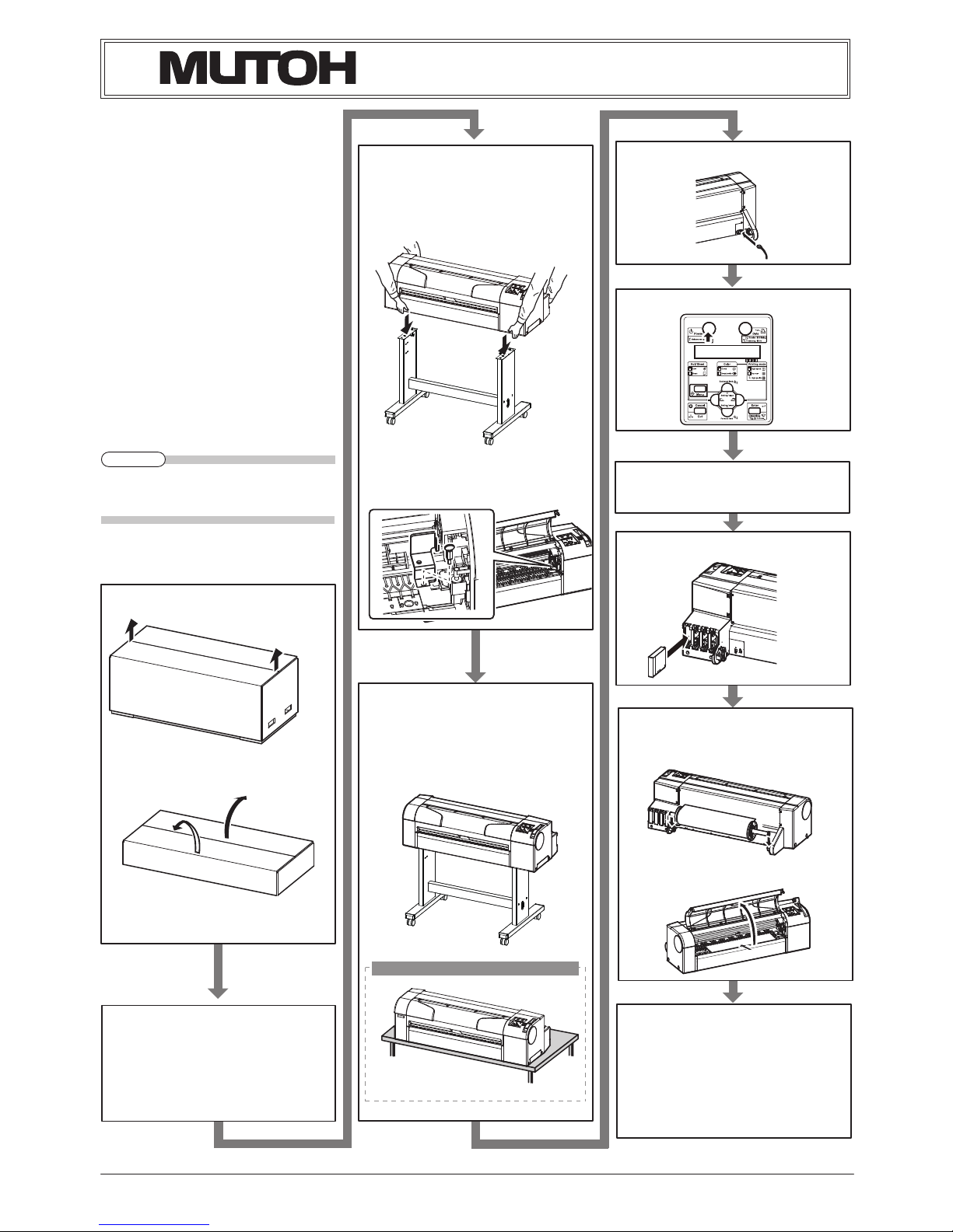
Installation flow chart
The broad steps for installation are shown below.
Follow the instructions beginning on the next
page.
The stands are optional depending on the
z
product and regions.
Unpacking boxes1
Unpacking the printer box1.1
Unpacking the stand box1.2
Confirming bundled items2
Items in the printer box2.1
Items in the attachment box2.2
Items in the stand box2.3
Assembling3
The stand assembling procedure3.1
Assembling the stand3.2
Detaching protective materials3.3
Installation4
Installation environment4.1
Installation procedure4.2
Connecting the power cable5
Turning the power ON/OFF6
Activating the printer7
Setting the display language8
Installing the ink cartridge9
Loading the media10
Loading the roll media10.1
Loading the sheet media10.2
Check the printing condition11
Installing the printer driver12
About printer driver13
Manual composition14
NOTE
8IFOVTJOHUIFQSJOUFSPOMZ
Page 2
RJ-900X series INSTALLATION MANUAL
RJ900XE-I-00
2
Unpacking boxes1
Procedures for unpacking boxes are explained.
This product is packaged separately, divided
into the printer and the stand.
Unp acking this pro duct r equir es the
・
following number of people.
RJ-901X : Two or more
・
RJ-900X : Three or more
・
While taking out the printer from the box,
・
make sure to remove the vinyl sheet
Unpacking printer box1.1
Unpack the printer box in accordance with the
following steps.
Carr y the box to where you will unpack it.
1.
Remove the bands.
2.
Open the box and take out the following
3.
components.
Installation Manual (this ma nual)・
Attachment box・
Scroller・
Unpacking stand box1.2
Unpack the st and box in accordance with the
following steps.
Carr y the box to where you will unpack it.
1.
Open the box and take out the components.
2.
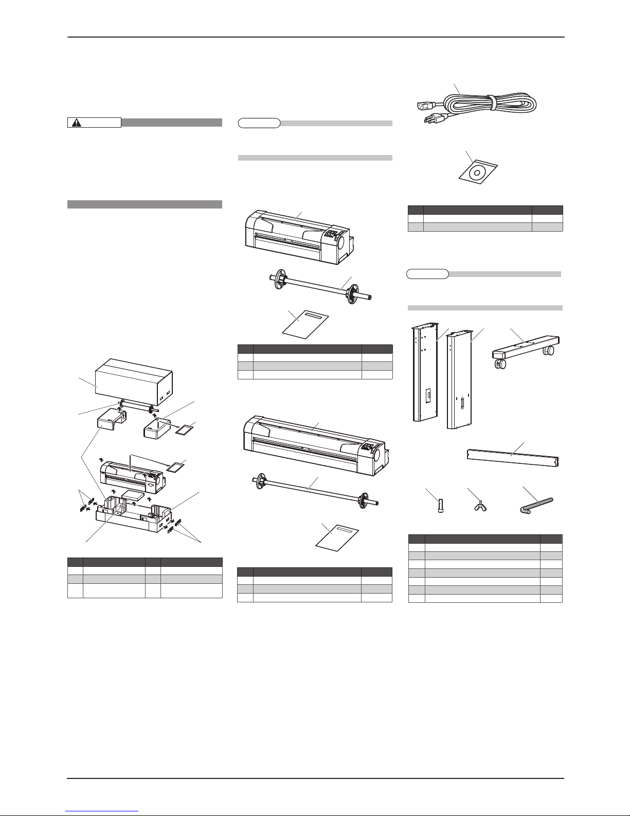
Confirming bundled items2
After unpacking, please conf irm that the product
has not damaged and no components are miss-
ing.
If anyitems are damaged or missing, con-
z
tact MUTOH local dealer.
Items in the printer box2.1
(1) RJ-901X
(2) RJ-900X
Items in the attachment box2.2
Items in the stand box2.3
The stands are optional depending on the
z
product and regions.
No. Name Q'ty
1 Prin ter mai n body 1 set
2 A1 Scrolle r 2 inch 1
3 Inst allatio n Manual (th is manual) 1
No. Name Q'ty
1 Power cable 1
2 Driver s and Manuals C D-ROM 1
No. Name No. Name
1 Prin ter box 4 Handle s (RJ-901X only)
2 Scrolle r 5 Atta chment box
3 Packi ng mater ial 6 Installat ion Manual
(this ma nual)
3+9
3+9
No. Name Q'ty
1 Le ft suppo rt 1
2 R ight supp ort 1
3 Ca ster section (l eft, rig ht) 2
4 Ce ntral beam 1
5 Hex agon socket h ead cap sc rew 8
6 But terfly b olt 2
7 Hex agonal wr ench 1
No. Name Q'ty
1 Prin ter mai n body 1 set
2 A0 Scrolle r 2 inch 1
3 Inst allatio n Manual (th is manual) 1
CAUTION
NOTE
NOTE
Page 3
RJ-900X series INSTALLATION MANUAL
RJ900XE-I-00
3
Assembling3
Procedures for assembling this product are
explained.
Unp acking this pro duct r equir es the
・
following number of people.
RJ-901X : Two or more
・
RJ-900X : Three or more
・
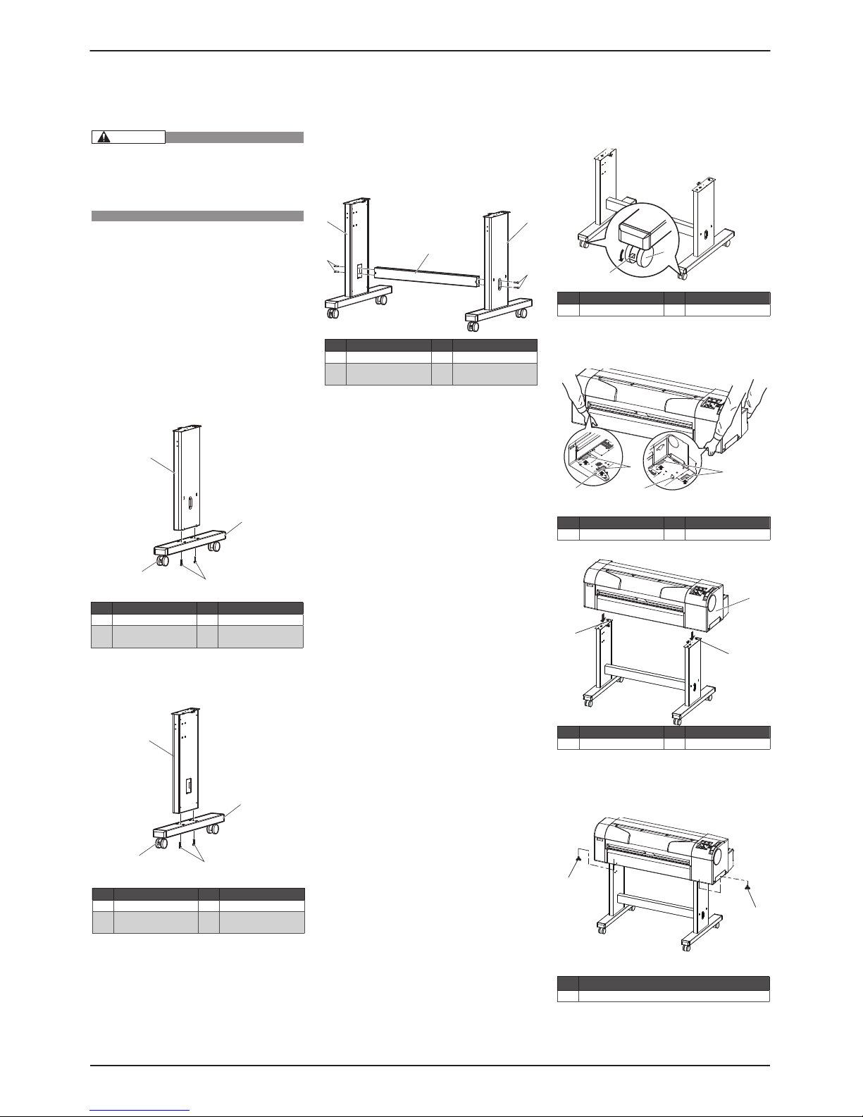
The stand assembling procedure3.1
If you will use the stand, assemble it in accor-
dance with the following steps.
Follow the steps shown below to assemble
1.
the right side of the stand.
Install the (right) support to the leg so that
a.
the caster with the lock is on the front.
Fasten two hexagon socket head cap screws
b.
with the enclosed hexagonal wrench.
Assemble the left side of the stand in a simi-
2.
lar way to step 1.
Follow the steps shown below to attach the
3.
central beam to the legs (left, right).
a.
Attach the central beam and four hexagon
socket head cap screws to the sta nd (the
left, the right).
Fasten the hexagon socket head cap screws
b.
with the enclosed hexagonal w rench, and
fasten the central beam.
Attach two arm holders to the legs (left,
4.
right).
Confirm that each component is fastened
5.
fir mly by gently shaking the stand.
Assembling the stand3.2
Attach the stand to the printer in accordance
with the following steps.
Lock two casters on the front side.
1.
Lift the printer main body, and align the rear
2.
side rubber feet to the holes of the stand.
Attach two butterfly bolts to the stand.
3.
Secure the printer to the st and by bolting the
4.
butterfly bolts.
This completes assembling of the stand.・
No. Name No. Name
1 Right s upport 3 Caste r section
2 Caste r lock 4 Hexagon socket h ead
cap scre ws
No. Name No. Name
1 Lerf t support 3 Caste r section
2 Caste r lock 4 Hexagon socket h ead
cap scre ws
No. Name No. Name
1 Centr al beam 3 Leg (righ t)
2 Leg (lef t) 4 Hexagon so cket head
cap scre w
No. Name No. Name
1 Caste rs 2 Caster lock s
No. Name No. Name
1 Grip s 2 Rubbe r feet
No. Name No. Name
1 Prin ter mai n body 2 Holes of the st and
No. Name
1 Butte rfly bolts
CAUTION
Page 4
RJ-900X series INSTALLATION MANUAL
RJ900XE-I-00
4
Detaching protective materials3.3
This product has protective materials in the
place shown below.
Detach all protect ive materials in accordance
with the following steps.
Remove all tapes from each cover.
1.
Open the front cover and unscrew the but-
2.
terf ly screws, and detach the f ixing head unit
protective materials (metal plate).
This completes detaching protective materials.・
Installation4
Procedures and environment for installing this
product are explained.
Installation environment4.1
Install this product to the appropriate place with
reference to the following.
Do not install the printer in the follow-
z
ing places where there is a possibility
that the print er ma y b e d am ag ed or
might fall or be fallen by chance.
On a shaky stand•
Slanting location•
Places where vibration of other ma-•
chines etc. is transmitted.
Do not s tam p o n th e prin ter or do
z
not place heavy things on top of it. It
may cause an injury if the printer falls
down.
Co ve r the p rinte r wit h blan ke t and
z
cloth like tablecloth and do not close
th e ven t . If the v ent i s clos ed, t he
printer could ac cumulate he at insid e
and may cause fire.
Do not install the printer in a location
z
that has high humidit y or is dusty. It
could lead to electric shock and fire.
Installation environment4.1.1
Select an installation location in accord ance
with the t able below.
For temperature and humidity, avoid locations
z
such as the following. The re is a possibility
that the print quality will be affected.
Places where temperature or humidity may
・
rapidly change, even though within the re-
quired conditions.
Place that receives direct sunlight or st rong
・
illumination light
Place that receives direct wind from an air
・
conditioner, and so on
To keep the temp erature and humidit y con-
z
stant, install this product in a location where
the air condition is adjstable.
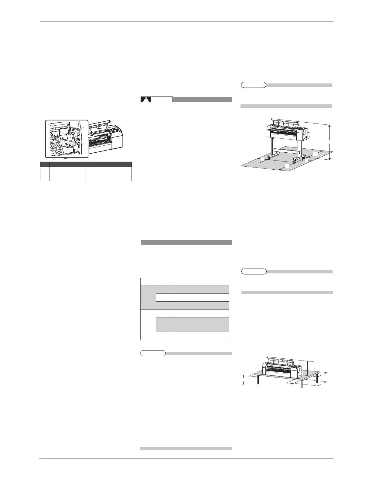
Installation space4.1.2
When using the printer with the stand・
Install on a level floor which meets the following
condition.
It has enough strength to support the weight ・
of the printer and the stand.
For the weight of the printer and the stand,
z
refer to the Operation Manual.
When using the printer only (RJ-901X)・
Install on a level table that meets the following
conditions.
The table has enough strength to support the ・
weigh of the printer.
For the weight of the pri nter, refer to the Op-
z
eration Manual.
The re quired leng th for the sheet med ia is ・
available in the back.
The he ig ht fro m the f loo r is 60 0 mm to ・
800 mm.
The space in the front is more than 300 mm.・
Printed sheets are not folded or dirtied.・
B
C
D
E
F
3+9
BNN
CNN
DNN
ENN
FNN
3+9
BNN
CNN
DNN
ENN
FNN
E
C
D
F
B
G
B
NN
CNN
DNN
ENN
FNN
GNN
Floor str ength of inst allation pla ce
More than 2 940 Pa (300 kg/m2)
Power
Specif ication
Power Supply
AC90V - 132V/198V - 264V
Frequenc y
Range
50/60Hz ±1Hz
Power
capacit y
More than 10 A
Environ mental
conditi ons
Operat ive
conditi on
Temperatu re:10 °C-35 °C
Humidit y: 20 % - 80 %, No Conden sation
Guara nteed
range of
print ing
accur acy
Temperatu re:15 °C - 28°C
Humidit y: 40 % - 60 %, No Conden sation
Change ra te Temper
ature: w ithin 2 °C per hour
Humidit y: within 5 % pe r hour
No. Name No. Name
1 Fixing h ead uni t protec-
tive mate rials (metal
plate)
2 Butte rfly screw
NOTE
NOTE
WARNING
NOTE
Page 5

RJ-900X series INSTALLATION MANUAL
RJ900XE-I-00
5
Installation procedure4.2
Install this product to the installation place in
accordance with the list shown below.
When using the printer 4.2.1
with the stand
Please check that the butterf ly bolts are not
z
loose before/after car ryi ng this product.
When transfer ring or carr ying outside, sepa-
rate the printer and the stand.
Check that the two butterf ly bolts attaching
1.
the stand and the printer are not loose.
Carr y the printer to the installation place.
2.
Lock two casters on the front side.
3.
Check that the two butterf ly bolts attaching
4.
the stand and the printer are not loose.
When using the printer 4.2.2
only (RJ-901X)
Install the printer so that the rubber foot (front) of
1.
the product is placed on the front of the board.
zWh en using the pr inter on ly (wi th ou t the
stand), always arrange as shown below.
There is a possibil ity that the printed sheets
are affected or errors such as media jams oc-
cur.
Connecting the power cable5
This section explains how to connect the power
cable. Follow the steps below to connect the
power cable.
Be su re to use the spe ci fi ed p ower
z
cable. Using a power cable other than
th e spe ci fi ed can ca us e an elect ri c
shock or fire.
Us e the powe r cable compliant with
z
the s af et y standards, p ower -s up pl y
voltage, and plug shape of the country
where the printer is used.
Use a power cable which is equipped
z
with a protective earth, and securely
connect it to the outlet.
Do not use a damaged power cable. It
z
could lead to an electric shock or fire.
Confirm that the product is turned OFF.
1.
Connect the power cable to the AC inlet on
2.
the back of the product.
Correctly insert the power cable plug into the
3.
power socket.
No. Name
1 Power cable
No. Name No. Name
1 Caste rs 2 Caster lock s
No. Name
1 Rubber fe et
No. Name No. Name
1 AC inlet 2 Power cable
NOTE
NOTE
WARNING
Page 6

RJ-900X series INSTALLATION MANUAL
RJ900XE-I-00
6
Turning the power ON /6
OFF
This section explains how to tu rn the printer
ON/OFF.
Turning the power ON6.1
Follow the procedure below to turn the power
ON.
Press the [Power] key on Operation panel to
1.
tur n ON the pri nter.
Power lamp on Operation panel lights up in ・
blue.
The printer starts the initial operation. ・
When the initial operation is complete, the ・
printer enters the Normal condition.
Turning the power OFF6.2
Follow the procedure below to turn the printer OFF.
Verify the following regarding the opera-
1.
tional condition of the pr inter.
Printing or other operations are not in prog-・
ress.
Operation panel display is Normal.・
Press the [Power] key on Operation panel to
2.
tur n OFF the pr inter.
Power lamp on Operation panel tur ns OFF.・
If Operation panel is in the following status,
z
the power is ON.
The [Power] key is pressed in.
・
Power lamp is ON.
・
Pre ss the key once aga in to tu rn the power
OFF.
The printer turns the power OFF.・
When the media is set, “Lift the lever” is dis-
z
played on O peration panel.Raise Media load-
ing lever.
“Wait for a while...” is displayed on Operation ・
panel.
All the lamps on Operation panel and the LCD ・
monitor are turned OFF.
The printer automatically turns the power OFF.・
After tur ning OFF t he printer, wait for ten sec-
z
onds or longer to tur n it ON again.
If you are not using the printer for a long
3.
time, raise Media loading lever.
Activating the printer7
This product requires activation when the power
is tur ned ON for the f irst time.
When “Activation required ” is displayed on
Operation panel, follow the “Printer activation
guide”* and perform activation.
*Download the “Pri nter activation guide” from
the following ValueJet Club.
https://mbss.mutoh.co.jp/mutoh/guser/
No. Name
1 Media loa ding lever
NOTE
NOTE
NOTE
Page 7

RJ-900X series INSTALLATION MANUAL
RJ900XE-I-00
7
Setting the display language8
After activation is complete, you need to make
the language setting when restarting the product.
Follow the procedures below to make setting.
Once act ivation is complete, “Reboot a
1.
printer” is displayed on Operation panel.
Press the [Power] key on Operation panel
and turn OFF the printer.
Press the [Power] key on Operation panel to
2.
tur n ON the pri nter.
“Language: Japanese” is displayed on Opera-・
tion panel.
Press the [Enter] key.
3.
Press the [+] key or [-] key on Operation panel ・
to select a set up item and press the [Enter]
key.
This completes the setting of display lan-・
guage.
The printer starts the initial operation.・
When the initial operation is complete, the ・
printer enters Normal.
Installing the ink cartridge9
This section explains about how to install the
ink cartridge. Follow the steps below to install the
ink cartr idge.
While handling ink cartridges, be care-
・
fu l tha t the ink do es not co me i nt o
contact with your eyes or skin. If the
ink got into your eyes or attac hed to
the skin, immediately wash with water.
Failing to do so may cause irrita tion
and light inflammation of the eyes. In
case of any abnormality, consult a phy-
sician immediately.
Turn ON the product.
1.
The product star ts the initial operation.
2.
The operation panel displays “No ink car t-・
didge ****”
Take out the ink cartridge from the bag.
3.
Install the ink cartridge into the ink cartridge
4.
slot.
Inser t the in k cartridge into the product with ・
mark upside.
Inser t the ink car tridge all the way to the end
z
of the slot.
Inser t all four i nk car tridges.
z
Make sure that the ink cartridges are inserted
z
into the cor rect slots. Match the mark in front
of the slot and the color of the ink before in-
serting the ink cartridge.
Ink cartridges a re structured to avoid wrong
z
inser tion.If you cannot insert the in k cartridg-
es into the slot smoothly, you may be inserting
it into a wrong slot. Do not insert it forcef ully.
No. Name No. Name
1 Ink ca rtridge 4 I nk cartr idge slot M
2 Ink ca rtridge slot K 5 Ink ca rtridge slot Y
3 Ink ca rtridge slot C
NOTE
NOTE
Page 8

RJ-900X series INSTALLATION MANUAL
RJ900XE-I-00
8
“Ink Ref ill ** min” is displayed, and the ink
5.
star ts the Initial in k charge.
It takes about 5 minutes. In the initial opera-・
tion, the product repeats in k filling and paus-
ing.
Comply strictly with the following dur-
・
ing ink filling.
Do not turn the printer OFF.
・
Do not unplug the power cord set of
・
the printer.
Do not open the front cover.
・
Do not open the maintenance cover.
・
Do not raise the media loading lever.
・
If the in k fin ishes being filled, the operation
6.
panel displays “Paper End ”.
If the paper is printed just after the initial f ill-
z
ing, the following conditions may occu r.
The printed line is blurred.
・
The white line appears on the prints.
・
In such cases, refer to the following to refill a
small amount of ink, and then check the print-
ing result.
Operation manual “5.2.3 Head Cleaning”
If there is no improvement in the print result
z
even af te r refi ll ing a small amount of i nk,
leave the printer unused for an hour or more.
Then, refill a small amount of ink again and
check the print result.If the pri nt result still
remains the same, contact the following.
Operation panel “7.4.2 Technical Support”
Loading the media10
Loading the roll media10.1
This section explains about how to load the roll media.
Put the roll media in the center of the printer.
Follow the steps to load the media.
When using roll media of three-inch di-
1.
ameter media tube, the optional three-inch
attachment should be used to the movable
flange and fixed flange.
Load the roll media into the scroller so that
2.
the roll media gets winded up in the anti-
clockwise direction in the view from the
fixed f lange side.
Push the roll media completely until the roll
3.
media core hits the right edge of the fixed flange.
Attach the movable flange until it fir mly
4.
sticks to the roll media core.
Set the scroller onto the scroller receiver so
5.
that the f ixed f lange heads for the ink car-
tridge side.
Turn ON the product.
6.
The product star ts the initial operation.・
The operation panel displays “Paper End”.・
Select “Roll media” by pressing [ 前 ] key on
7.
the operation panel.
Roll media lamp lights up.・
Push the media loading lever back ward.
8.
The operation panel displays “Lever Up”.・
Feed the roll media into the media feed slot.
9.
Open the front cover, and pull out the roll
10.
media.
No. Name No. Name
1 Roll medi a 2 Med ia feed slot
No. Name No. Name
1 Scrolle r 3 Ink ca rtridge slot
2 Fixed f lange 4 Scrolle r receiver
No. Name No. Name
1 Movable f lange 3 Thre e-inch atta chment
2 Fixed f lange
No. Name No. Name
1 Movable f lange 2 Roll medi a
No. Name No. Name
1 Movable f lange 2 Roll medi a
No. Name
1 Media loa ding lever
No. Name No. Name
1 Front cover 2 Roll media
CAUTION
NOTE
Page 9

RJ-900X series INSTALLATION MANUAL
RJ900XE-I-00
9
Wind back the roll media with scroller while
11.
pressing down the media edge, remove bend-
ing and slant of the media.
Return the media loading lever to your front,
12.
and close the f ront cover.
The operation panel displays the media type ・
setup menu.
Press the [Setting value +] key or [Setting
13.
value -] key on the operation panel, and enter
the selected number.
The media type is entered.・
The operation panel displays “Paper In itial”, ・
and media starts the initial operation.
After finishing the media initial operation, the ・
operation panel displays “Ready to Plot”, and
the product tur ns to a nor mal operation.
Wind back the roll media with scroller to
14.
remove bending and slant of the media.
The media loading is complete.・
Loading the sheet media10.2
This section explains about how to load the sheet
media.
Follow the steps below to load the sheet media.
Turn ON the product.
1.
The product star ts the initial operation.
2.
The operation panel displays “Paper End”.・
Select “Sheet media” by pressing [ 前 ] key
3.
on the operation panel.
Sheet media lamp lights up.・
Push the media loading lever back ward.
4.
The operation panel displays “Lever Up”.・
Open the front cover, and insert the sheet
5.
media in to the media feed slot.
Align the right end of media to the media
6.
loading mark, and align the f ront edge to the
step of platen respectively.
If the sheet media right end shi fts either t o
z
the right or the left from the loading mark, it
would become as media loading error without
media bei ng detected.
Load the media within the z±5 mm range from
the loading mark.
Return the media loading lever to your front
7.
and close the f ront cover.
The operation panel displays the media type ・
setup menu.
In the same way as step 13 in “10.1 Loading
8.
the roll media”, make the media type setting.
When the media ty pe is entered, the operation ・
panel displays “Paper Initial”, and media starts
the initial operation.
After finishing the media initial operation, the ・
operation panel displays “Ready to Plot”, and
the product tur ns to a nor mal operation.
The media loading is complete.・
No. Name No. Name
1 Roll medi a 2 Scr oller
No. Name No. Name
1 Media loa ding lever 2 Front cover
No. Name
1 Media loa ding lever
No. Name No. Name
1 Roll medi a 2 Scr oller
No. Name No. Name
1 Media loa ding lever 2 Front cover
No. Name No. Name
1 Front cover 2 Sheet med ia
No. Name No. Name
1 Sheet med ia 3 S tep of plate n
2 Media loa ding mark
NOTE
Page 10

RJ-900X series INSTALLATION MANUAL
RJ900XE-I-00
10
Check the printing condition11
Check the print head condition af ter in k initial
filling.
Turn ON the power to the printer, and set A3
1.
or larger sheet media or roll media.
10. Loading the media
Check that “Ready to Print” is displayed on
2.
Operation panel.
Press the [Menu] key on the operation panel.
3.
“*Menu* TestPlot >” is displayed on the opera-・
tion panel
Operation panel shifts to the Setup menu display.・
Press the [Enter] key on Operation panel .
4.
“TestPlot: SetupPlot” is displayed on the op-・
eration panel
Display shifts to Test print menu.・
Press the [Setting value +] key or [Setting
5.
value-] key on the operation panel, select
“Nozzle check” and press the [Enter] key.
Perform t he nozzle check printing.・
Check the print sample and conf irm that the
6.
checked points are blur red or mi
ssing.
If the nozzle check result indicates that the
7.
checked points are blur red or missing, clean
the head.
Press the [Cleaning] key on the operat ion ・
panel for at least 2 seconds.
“Cleaning ** min” is displayed on the opera-・
tion panel.
Start head cleaning.
8.
If print blu rs or incomple te printi ng is not
z
fi xed by one hea d cleani ng, perform strong
cleaning.
If sever al he ad clea ni ng s does not remove
z
print blur or incomplete pr inting, refer to the
following and perform required procedures.
Operation Manual "6 Troubleshooting"
Perform t he nozzle check again, and confirm
9.
the print head condition.
Installing the printer driver12
For network connection12.1
This section explains how to connect to the
Inter net (TCP/IP).
Turn ON the power to the printer.
1.
Set the IP address for the printer.
2.
For the procedure to set IP addresses, refer to
z
“3.6.5 Setting IP Addresses” in the Operation
manual.
You can view the Operat ion manual from the
z
CD-ROM (“Drivers and Manuals CD -ROM”)
included with the product.
The language preference screen is displayed
・
when you start the CD-ROM.Click the language you want, and then click “Viewing
the Operation manual” on the next screen.
Inser t the network interface cable connector
3.
into the network interface connector located
on the back of the printer.
Fix the network interface cable to the cable
4.
clamp.
Connect the another network interface cable
5.
connector to the PC.
Turn ON the power to the PC.
6.
NOTE
No. Name No. Name
1 Network i nterfa ce cable 2 Cable cla mp
No. Name No. Name
1 Network i nterface cabl e 2 Network i nterface con -
nector
NOTE
Page 11

RJ-900X series INSTALLATION MANUAL
RJ900XE-I-00
11
Ensure that your PC boots up correctly, and
7.
inser t the CD-ROM on which “Windows
printer driver” is writ ten into the CD-ROM
drive on your PC.
The lang uage preference screen is displayed.・
Click the language you want to use.
8.
Click “Install the printer driver” on the next
9.
screen.
The installer st arts up.
10.
For the details of installation, refer to “3.7.2 In-
z
stallation procedure of the printer driver (network connection)” in the Operation manual.
For USB connection12.2
This section explains how to connect USB device.
Do not connect the USB cable before install-
z
ing the pr in ter driver.Otherwise the d river
cannot be installed correctly.
If you have connected the USB cable first by
z
mistake, check “6.1.1.1 If You Con nect USB
before Installing Driver”.
Turn ON the power to the PC.
1.
Ensure that your PC boots up correctly, and
2.
inser t the CD-ROM on which “Windows
printer driver” is writ ten into the CD-ROM
drive on your PC.
The lang uage preference screen is displayed.・
Click the language you want to use.
3.
Click “Install the printer driver” on the next
4.
screen.
The installer st arts up.
5.
For deta il s abou t insta ll in g, refer to “3.7.3
z
Installing the printer driver (for USB con nection)” on the Operation manual.
You can view the Operat ion manual from the
z
CD-ROM (“Drivers and Manuals CD -ROM”)
included with the product.
The language preference screen is displayed
・
when you start the CD-ROM.Click the language you want, and then click “Viewing
the Operation manual” on the next screen.
Connecting the USB cable12.2.1
Inser t the USB cable into the USB connector
1.
on the back of the printer.
Fix the USB cable to the cable clamp.
2.
No. Name No. Name
1 USB cable 2 Cable clam p
No. Name No. Name
1 USB cable 2 USB conne ctor
NOTE
NOTE
NOTE
Page 12

MUTOH INDUSTRIES LTD.
Tel.:81-(0)3-6758-7020
Fax :81- (0)3 -675 8-702 5
E-mail:ibd@mutoh.co.jp
http://www.mutoh.co.jp/en/
index.html
MUTOH North Europe S.A.
Tel.:352-445-906
Fax:352-447-093
E-mail:info@segroup.lu
http://www.segroup.lu/
MUTOH AMERICA INC.
Tel.:1-480-968-7772
Fax:1-480-968-7990
E-mail:sales@mutoh.com
http://www.mutoh.com
MUTOH BELGIUM nv
Tel.:32-(0)59-561400
Fax:32-(0)59 -807117
E-mail:mutoh@mutoh.be
http://www.mutoh.be
MUTOH DEUTSCHLAND GmbH
Te l . :4 9 - ( 0) 211 -3 8 5 474 - 0
Fa x:4 9- (0) 211-38 5474 -74
E-mail:vertrieb@mutoh-gmbh.de
http://www.mutoh.de
MUTOH HONGKONG LTD.
Tel.:852-2377-3411
Fax: 852-2377-342 2
http://www.mutoh.co.jp/
en/index.html
MUTOH SINGAPORE PTE.LTD.
Tel.:65-6325-3150
Fax:65-6220-4342
E-mail:sales_inq@mutoh-sg.com
http://www.mutoh.co.jp/en/
index.html
MUTOH AUSTRALIA PTY.LTD.
Tel.:61-2-9437-1336
Fax:61-2-9436-2871
E-mail:sales@mutoh-au.com
http://mutoh-au.com
Printer driver13
Printer driver is used to print and output the
print data created with Windows application
software to the printer.
Setting the printer driver13.1
Follow the procedure below to configu re the fol-
lowing items.
Selecting the printer driver
1.
Setti ng the printer driver
2.
For the set up procedure of t he pri nter driver,
z
refer to “4.4 Setting Printer Driver” in the Op-
eration manual or the attached help file. The
file will be displayed by clicking [HELP] on
the printer dr iver setup screen.
Product Activation Guide14
This product includes the following manuals.
Installation Manual (this manual)・
Th is ma nu al ex pl ain s t he proc edu re s of
unpacking, installing, and basic set up.
Product Activation Guide・
This manual explains the operation procedure
when you start the printer for the first time.
Operation Manual (CD-ROM)・
O p e r a t i o n Ma nu al exp l a i n s th e b a s i c
installation, daily use and applicable functions.
Download the “Printer activation g uide” f rom
z
the following ValueJet Club.
https://mbss.mutoh.co.jp/mutoh/guser/
You can view the Operation manual from the
z
CD-ROM (“Drivers and Manuals CD-ROM”)
included with the product.
Th e lan gua ge pr eferen ce sc re en is dis -
・
played when you start the CD-ROM. Click
th e lang u ag e you wan t, a nd t he n click
“Vi ewing th e Oper at ion ma nu al ” on the
next screen.
You can use a browser such as Internet Explor-
z
er to view the HTML page thatʼs displayed to
select the lang uage when you start the CD-
ROM.
The Operation manual of this printer is a PDF
z
format.
Adobe Acrobat Reader 5.0 or later is required
to view a PDF f ile.You can download Adobe
Reader from the Adobe web site for free.
NOTE
NOTE
 Loading...