

Page 1
Service
Manual
For machine versions:
A1, A2, A3 and A4
Based on firmware version 3.0.0
& Mutoh CutServer version 3.0.0
For service technicians only!
Page 2

Page 3

Service manual Kona cutting plotter
Copyright notice
COPYRIGHT © 27/4/10 Mutoh Europe nv All rights reserved.
Mutoh Europe nv reserves the right to modify the information contained in this manual at any
time without prior notice.
This document may not be reproduced by any means, in whole or in part, without written
permission of the copyright owner.
Mutoh furnished this document to support the Kona cutting plotter series. In consideration of
the furnishing of the information contained in this document, the party to whom it is given,
assumes its custody and control and agrees to the following:
The information herein contained is given in confidence, and any part thereof shall not be
copied or reproduced without written consent of Mutoh Europe nv
This document or the contents herein under no circumstances shall be used in the
manufacture or reproduction of the article shown and the delivery of this document shall not
constitute any right or license to do so.
AP-74380 - Revision 1.0 3
Page 4
Service manual Kona cutting plotter
Parts replacement summary
The Service manual contains all necessary replacement procedures for every spare part
available for the Kona. Though, when replacing parts it might be possible that there are
additional actions necessary.
Please find below an overview:
1. Pen head replacement page44
Perform Y-Z measurement (diagnostics) page93
Adjust sheeting-off knife position page91
Perform EPOS calibration page103
2. Mainboard replacement page67
Before mainboard replacement
Take back-up parameters using the Mutoh CUTserver page98
After mainboard replacement
Uninstall and reinstall USB drivers on PC page96
Load firmware via USB. page94
Restore back-up parameters using the Mutoh CUTserver page99
If there are no back-up parameters available, you have to do the
following:
Calibrate X and Y distance accuracy using the Mutoh CUTserver page102
Perform Y-Z measurement (diagnostics) page93
Perform EPOS calibration page103
3. Y-motor or Y speed reduction belt replacement page35
Adjust speed reduction belt to 3.5 kg page87
4. X-motor replacement page33
Adjust belt tension to 3.5 kg page86
5. Pressure roller assembly replacement page61
Adjust pressure of pressure rollers to 5,5 kg page90
4 AP-74380 - Revision 1.0
Page 5

Service manual Kona cutting plotter
Table of contents
Chapter 1 Regulations and safety information . . . . . . . . . . . . . 9
1.1 Warnings, cautions and notes . . . . . . . . . . . . . . . . . . . . . . . . . 10
1.2 Compliance with the following regulations . . . . . . . . . . . . . . 10
1.3 Important notes . . . . . . . . . . . . . . . . . . . . . . . . . . . . . . . . . . . . . 11
1.4 Safety labels. . . . . . . . . . . . . . . . . . . . . . . . . . . . . . . . . . . . . . . . 12
Chapter 2 Product overview . . . . . . . . . . . . . . . . . . . . . . . . . . . 13
2.1 Dimensions machine. . . . . . . . . . . . . . . . . . . . . . . . . . . . . . . . . 14
2.2 Installation environment requirements . . . . . . . . . . . . . . . . . . 14
Power supply . . . . . . . . . . . . . . . . . . . . . . . . . . . . . . . . . . . . . . . . . . . . 14
Ambient conditions. . . . . . . . . . . . . . . . . . . . . . . . . . . . . . . . . . . . . . . . 14
Room conditions. . . . . . . . . . . . . . . . . . . . . . . . . . . . . . . . . . . . . . . . . . 15
2.3 Part names and functions. . . . . . . . . . . . . . . . . . . . . . . . . . . . . 16
2.4 Overview operation panel. . . . . . . . . . . . . . . . . . . . . . . . . . . . . 17
Main menu. . . . . . . . . . . . . . . . . . . . . . . . . . . . . . . . . . . . . . . . . . . . . . . 17
Settings or actions menu. . . . . . . . . . . . . . . . . . . . . . . . . . . . . . . . . . . 18
Adjust value menu . . . . . . . . . . . . . . . . . . . . . . . . . . . . . . . . . . . . . . . . 19
2.5 Menu overview. . . . . . . . . . . . . . . . . . . . . . . . . . . . . . . . . . . . . . 20
User mode. . . . . . . . . . . . . . . . . . . . . . . . . . . . . . . . . . . . . . . . . . . . . . . 20
Diagnostics mode 1 and 2 . . . . . . . . . . . . . . . . . . . . . . . . . . . . . . . . . 23
2.6 Machine version . . . . . . . . . . . . . . . . . . . . . . . . . . . . . . . . . . . . 24
AP-74380 - Revision 1.0 5
Page 6

Service manual Kona cutting plotter
Chapter 3 Part replacement. . . . . . . . . . . . . . . . . . . . . . . . . . . . 25
3.1 Cover removal . . . . . . . . . . . . . . . . . . . . . . . . . . . . . . . . . . . . . . 27
Side covers . . . . . . . . . . . . . . . . . . . . . . . . . . . . . . . . . . . . . . . . . . . . . . 28
Y-rail cover . . . . . . . . . . . . . . . . . . . . . . . . . . . . . . . . . . . . . . . . . . . . . . 29
Penhead cover . . . . . . . . . . . . . . . . . . . . . . . . . . . . . . . . . . . . . . . . . . . 30
Front platen. . . . . . . . . . . . . . . . . . . . . . . . . . . . . . . . . . . . . . . . . . . . . . 31
Rear platen . . . . . . . . . . . . . . . . . . . . . . . . . . . . . . . . . . . . . . . . . . . . . . 32
3.2 X-motor and drive belt . . . . . . . . . . . . . . . . . . . . . . . . . . . . . . . 33
3.3 Y-motor assembly . . . . . . . . . . . . . . . . . . . . . . . . . . . . . . . . . . . 35
Exploded view. . . . . . . . . . . . . . . . . . . . . . . . . . . . . . . . . . . . . . . . . . . . 35
Y-motor . . . . . . . . . . . . . . . . . . . . . . . . . . . . . . . . . . . . . . . . . . . . . . . . . 36
Y-drive pulley and speed reduction belt . . . . . . . . . . . . . . . . . . . . . . 38
Y-return pulley . . . . . . . . . . . . . . . . . . . . . . . . . . . . . . . . . . . . . . . . . . . 39
3.4 Penhead assembly . . . . . . . . . . . . . . . . . . . . . . . . . . . . . . . . . . 40
Exploded view. . . . . . . . . . . . . . . . . . . . . . . . . . . . . . . . . . . . . . . . . . . . 40
Penhead FFC (flexible flat cable). . . . . . . . . . . . . . . . . . . . . . . . . . . . 41
Penhead assembly . . . . . . . . . . . . . . . . . . . . . . . . . . . . . . . . . . . . . . . 44
Penhead drive belt . . . . . . . . . . . . . . . . . . . . . . . . . . . . . . . . . . . . . . . . 47
Sheet-off mechanism. . . . . . . . . . . . . . . . . . . . . . . . . . . . . . . . . . . . . . 49
EPOS sensor block . . . . . . . . . . . . . . . . . . . . . . . . . . . . . . . . . . . . . . . 50
Y-origin flex PCB . . . . . . . . . . . . . . . . . . . . . . . . . . . . . . . . . . . . . . . . . 52
3.5 Grit shaft. . . . . . . . . . . . . . . . . . . . . . . . . . . . . . . . . . . . . . . . . . . 53
Exploded view. . . . . . . . . . . . . . . . . . . . . . . . . . . . . . . . . . . . . . . . . . . . 53
Grit shaft and support rollers . . . . . . . . . . . . . . . . . . . . . . . . . . . . . . . 54
3.6 Pressure roller assembly . . . . . . . . . . . . . . . . . . . . . . . . . . . . . 59
Exploded view. . . . . . . . . . . . . . . . . . . . . . . . . . . . . . . . . . . . . . . . . . . . 59
Pressure roller . . . . . . . . . . . . . . . . . . . . . . . . . . . . . . . . . . . . . . . . . . . 60
Pressure roller assembly. . . . . . . . . . . . . . . . . . . . . . . . . . . . . . . . . . . 61
3.7 Cutting mat. . . . . . . . . . . . . . . . . . . . . . . . . . . . . . . . . . . . . . . . . 66
6 AP-74380 - Revision 1.0
Page 7

Service manual Kona cutting plotter
3.8 Electronics . . . . . . . . . . . . . . . . . . . . . . . . . . . . . . . . . . . . . . . . . 67
Mainboard . . . . . . . . . . . . . . . . . . . . . . . . . . . . . . . . . . . . . . . . . . . . . . . 67
X and Y motor fuse . . . . . . . . . . . . . . . . . . . . . . . . . . . . . . . . . . . . . . . 74
Penhead PCB. . . . . . . . . . . . . . . . . . . . . . . . . . . . . . . . . . . . . . . . . . . . 75
Power supply . . . . . . . . . . . . . . . . . . . . . . . . . . . . . . . . . . . . . . . . . . . . 78
Touchscreen . . . . . . . . . . . . . . . . . . . . . . . . . . . . . . . . . . . . . . . . . . . . . 80
Sensors . . . . . . . . . . . . . . . . . . . . . . . . . . . . . . . . . . . . . . . . . . . . . . . . . 81
Vacuum fans. . . . . . . . . . . . . . . . . . . . . . . . . . . . . . . . . . . . . . . . . . . . . 83
Chapter 4 Adjustments and calibrations . . . . . . . . . . . . . . . . . 85
4.1 Mechanical adjustments. . . . . . . . . . . . . . . . . . . . . . . . . . . . . . 86
X drive belt tension . . . . . . . . . . . . . . . . . . . . . . . . . . . . . . . . . . . . . . . 86
Y drive belt tension . . . . . . . . . . . . . . . . . . . . . . . . . . . . . . . . . . . . . . . 87
Penhead drive belt tension . . . . . . . . . . . . . . . . . . . . . . . . . . . . . . . . . 88
Pressure roller pressure . . . . . . . . . . . . . . . . . . . . . . . . . . . . . . . . . . . 90
Sheeting-off knife position. . . . . . . . . . . . . . . . . . . . . . . . . . . . . . . . . . 91
YZ measurement . . . . . . . . . . . . . . . . . . . . . . . . . . . . . . . . . . . . . . . . . 93
4.2 Software and drivers. . . . . . . . . . . . . . . . . . . . . . . . . . . . . . . . . 94
Download latest software and drivers . . . . . . . . . . . . . . . . . . . . . . . . 94
Firmware installation . . . . . . . . . . . . . . . . . . . . . . . . . . . . . . . . . . . . . . 94
How to uninstall the USB drivers . . . . . . . . . . . . . . . . . . . . . . . . . . . . 96
How to install the USB drivers . . . . . . . . . . . . . . . . . . . . . . . . . . . . . . 97
USB icon . . . . . . . . . . . . . . . . . . . . . . . . . . . . . . . . . . . . . . . . . . . . . . . . 97
4.3 Parameters. . . . . . . . . . . . . . . . . . . . . . . . . . . . . . . . . . . . . . . . . 98
Backup parameters of machine . . . . . . . . . . . . . . . . . . . . . . . . . . . . . 98
Restore parameters of machine. . . . . . . . . . . . . . . . . . . . . . . . . . . . . 99
4.4 Mutoh CutServer tests . . . . . . . . . . . . . . . . . . . . . . . . . . . . . . 100
Tracking test . . . . . . . . . . . . . . . . . . . . . . . . . . . . . . . . . . . . . . . . . . . . 100
XY-distance accuracy test . . . . . . . . . . . . . . . . . . . . . . . . . . . . . . . . 102
4.5 EPOS calibration . . . . . . . . . . . . . . . . . . . . . . . . . . . . . . . . . . . 103
AP-74380 - Revision 1.0 7
Page 8

Service manual Kona cutting plotter
Chapter 5 Diagnostics mode . . . . . . . . . . . . . . . . . . . . . . . . . . 105
5.1 Introduction . . . . . . . . . . . . . . . . . . . . . . . . . . . . . . . . . . . . . . . 106
5.2 How to start up in diagnostics mode 1 and 2 . . . . . . . . . . . . 106
Diagnostics 1 . . . . . . . . . . . . . . . . . . . . . . . . . . . . . . . . . . . . . . . . . . . 106
Diagnostics 2 . . . . . . . . . . . . . . . . . . . . . . . . . . . . . . . . . . . . . . . . . . . 107
5.3 Menu overview. . . . . . . . . . . . . . . . . . . . . . . . . . . . . . . . . . . . . 108
Connection . . . . . . . . . . . . . . . . . . . . . . . . . . . . . . . . . . . . . . . . . . . . . 109
Encoder . . . . . . . . . . . . . . . . . . . . . . . . . . . . . . . . . . . . . . . . . . . . . . . . 110
PWM test. . . . . . . . . . . . . . . . . . . . . . . . . . . . . . . . . . . . . . . . . . . . . . . 111
Defaults . . . . . . . . . . . . . . . . . . . . . . . . . . . . . . . . . . . . . . . . . . . . . . . . 112
Accuracy . . . . . . . . . . . . . . . . . . . . . . . . . . . . . . . . . . . . . . . . . . . . . . . 113
YZ profile . . . . . . . . . . . . . . . . . . . . . . . . . . . . . . . . . . . . . . . . . . . . . . . 114
Tool Force . . . . . . . . . . . . . . . . . . . . . . . . . . . . . . . . . . . . . . . . . . . . . . 115
Actuators . . . . . . . . . . . . . . . . . . . . . . . . . . . . . . . . . . . . . . . . . . . . . . . 115
Sensors . . . . . . . . . . . . . . . . . . . . . . . . . . . . . . . . . . . . . . . . . . . . . . . . 116
Aging . . . . . . . . . . . . . . . . . . . . . . . . . . . . . . . . . . . . . . . . . . . . . . . . . . 117
Screen . . . . . . . . . . . . . . . . . . . . . . . . . . . . . . . . . . . . . . . . . . . . . . . . . 119
Chapter 6 Troubleshooting . . . . . . . . . . . . . . . . . . . . . . . . . . . 121
6.1 Troubleshooting when no error is displayed . . . . . . . . . . . . 122
General troubleshooting . . . . . . . . . . . . . . . . . . . . . . . . . . . . . . . . . . 122
Recoverable error messages with no error ID number. . . . . . . . . 126
6.2 Troubleshooting when an error is displayed . . . . . . . . . . . . 128
Errors with error number (ID 1009-6115) . . . . . . . . . . . . . . . . . . . . 128
Contourcutting errors and warnings (ID 6201-6271). . . . . . . . . . . 131
MGL errors (ID 4000-5000) . . . . . . . . . . . . . . . . . . . . . . . . . . . . . . . 138
BREVID_ERROR_HW_REVISION (6110-6120) . . . . . . . . . . . . . 139
FPGA ERRORS (6140 - 6150) . . . . . . . . . . . . . . . . . . . . . . . . . . . . 140
RAM ERRORS . . . . . . . . . . . . . . . . . . . . . . . . . . . . . . . . . . . . . . . . . . 141
Other errors. . . . . . . . . . . . . . . . . . . . . . . . . . . . . . . . . . . . . . . . . . . . . 142
8 AP-74380 - Revision 1.0
Page 9

Service manual Kona cutting plotter
Regulations and safety information
Chapter1 Regulationsand
safetyinformation
Warnings, cautions and notes . . . . . . . . . . . . . . . . . . . . . . . . . . . . . . . . . 10
Compliance with the following regulations . . . . . . . . . . . . . . . . . . . . . . . 10
Important notes . . . . . . . . . . . . . . . . . . . . . . . . . . . . . . . . . . . . . . . . . . . . . 11
Safety labels . . . . . . . . . . . . . . . . . . . . . . . . . . . . . . . . . . . . . . . . . . . . . . . . 12
1
AP-74380 - Revision 1.1 9
Page 10
Service manual Kona cutting plotter
Regulations and safety information
1.1 Warnings, cautions and notes
Safety terms in this manual and the contents of warning labels attached to the cutter are
categorized into the following three types, depending on the degree of risk (or the scale of
accident).
Read the following explanations carefully and follow the instructions in this manual.
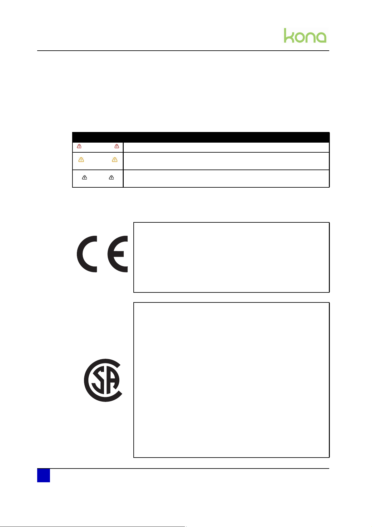
Safety terms Details
Important Must be followed carefully to avoid death or serious bodily injury.
Caution
Notes
Must be observed to avoid bodily injury (moderate or light) or damage to
your equipment.
Contains important information and useful tips on the operation of your
cutter.
1.2 Compliance with the following regulations
The CE marking is a mandatory European marking for certain
product groups to indicate conformity with the essential health and
safety requirements set out in European Directives.
By affixing the CE marking, the manufacturer, his authorized
representative, or the person placing the product on the market or
putting it into service ensures that the item meets all the essential
requirements of all applicable EU directives and that the applicable
conformity assessment procedures have been applied.
This product is tested and approved by the Canadian Standards
Association (CSA), this to provide increased assurance of quality and
safety.
The product is tested according to IEC60950.
This standard tries to cover all safety aspects.
Mechanical, electrical
Choice of components
Choice of materials: flammability!
Connectors, cables …
Fire enclosure
…
This means the product is safe for users, service personnel and
production personnel.
CSA International certification is not a legal commitment but it
assures the quality and safety of the machine.
10 AP-74380 - Revision 1.1
Page 11
Service manual Kona cutting plotter
Regulations and safety information
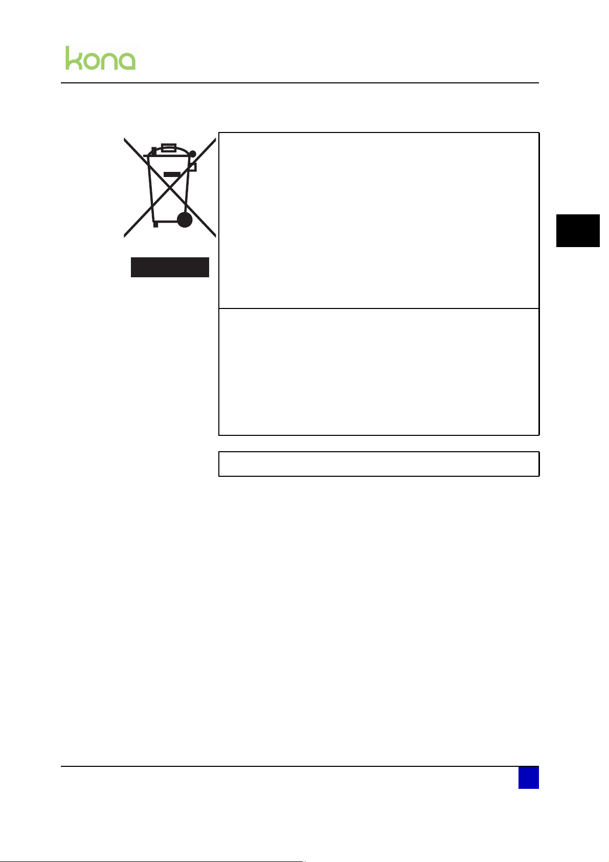
Your product is designed and manufactured with high-quality
materials and components, which can be recycled and reused.
When this crossed-out wheeled bin submenu is attached to a
product, it means the product is covered by the European Directive
2002/96/EC - WEEE regulation.
Please inform yourself about the local separate collection system for
electrical and electronic products.
Please act according to local rules and do not dispose of your old
products with your normal household waste. The correct disposal of
your old product will help prevent potential negative consequences
for the environment and human health.
This equipment has been tested and found to comply with the limits
for a Class A digital device, pursuant to Part 15 of the FCC Rules.
These limits are designed to provide reasonable protection against
harmful interference when the equipment is operated in a commercial
FCC
ICES
environment. This equipment generates, uses, and can radiate radio
frequency energy and, if not installed and used in accordance with
the instruction manual, may cause harmful interference to radio
communications. Operation of this equipment in a residential area is
likely to cause harmful interference in which case the user will be
required to correct the interference at his own expense.
This Class A digital apparatus complies with Canadian ICES-003.
1.3 Important notes
1
This machine has a double pole / neutral fusing.
Technical problems and maintenance, which require the cutter to be opened, can only be
done by qualified personnel who were trained to repair this type of machine.
Unauthorized removing of covers and/or overruling safety locks can be dangerous and will
result in your guarantee becoming void.
After powering OFF the machine, wait at least 10 seconds before powering ON again. Not
respecting this time interval could damage the machine.
The cutter must be connected to an earthed mains socket-outlet.
AP-74380 - Revision 1.1 11
Page 12
Service manual Kona cutting plotter
Regulations and safety information
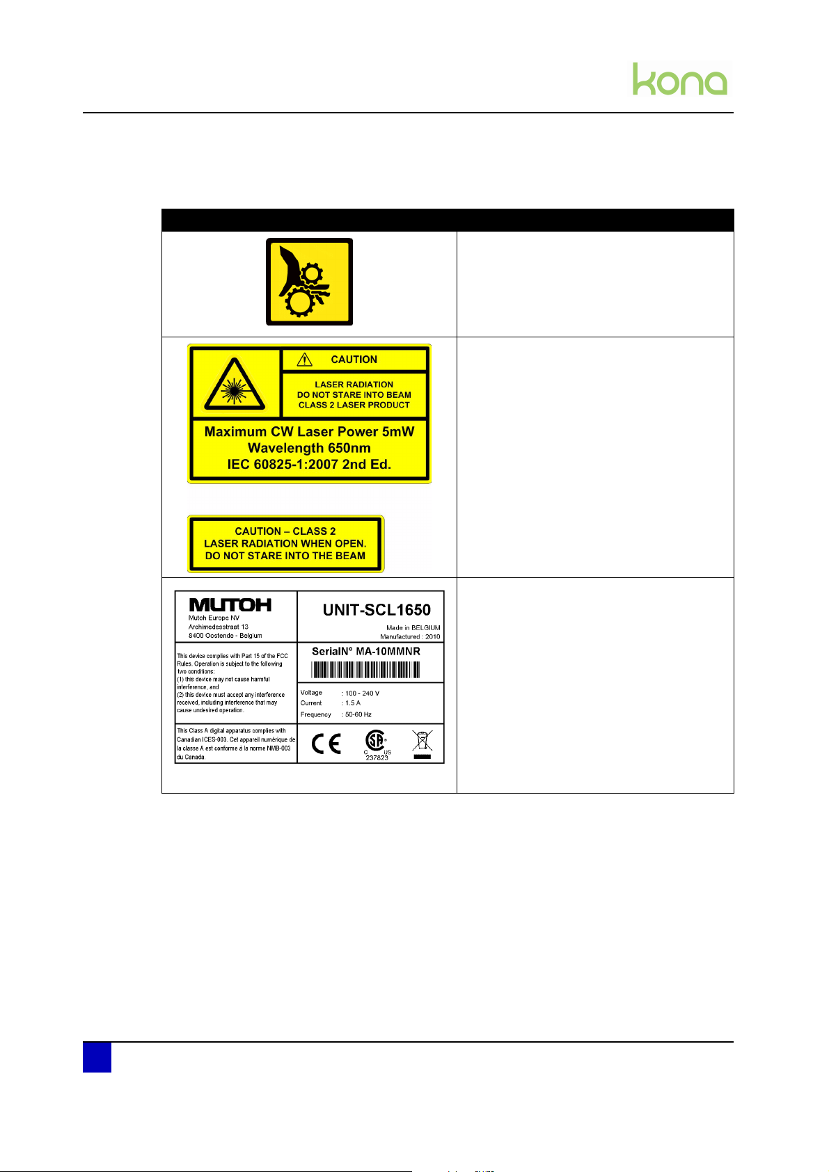
1.4 Safety labels
Label Description
Be careful not to get stuck between the
following moving parts:
Cutting head
Grit rollers
Be sure not to stare in the laser mounted
on the cutting head.
Serial number label providing you the
following information:
Serial number
Unit name
Power supply requirements
Regularisations
Class A product
Address Mutoh Europe n.v.
12 AP-74380 - Revision 1.1
Page 13

Service manual Kona cutting plotter
Product overview
Chapter 2 Product overview
Dimensions machine . . . . . . . . . . . . . . . . . . . . . . . . . . . . . . . . . . . . . . . . . 14
Installation environment requirements . . . . . . . . . . . . . . . . . . . . . . . . . . 14
Power supply . . . . . . . . . . . . . . . . . . . . . . . . . . . . . . . . . . . . . . . . . . . . . . . . . . 14
Ambient conditions. . . . . . . . . . . . . . . . . . . . . . . . . . . . . . . . . . . . . . . . . . . . . . 14
Room conditions . . . . . . . . . . . . . . . . . . . . . . . . . . . . . . . . . . . . . . . . . . . . . . . 15
Part names and functions . . . . . . . . . . . . . . . . . . . . . . . . . . . . . . . . . . . . . 16
Overview operation panel . . . . . . . . . . . . . . . . . . . . . . . . . . . . . . . . . . . . . 17
2
Main menu . . . . . . . . . . . . . . . . . . . . . . . . . . . . . . . . . . . . . . . . . . . . . . . . . . . . 17
Settings or actions menu . . . . . . . . . . . . . . . . . . . . . . . . . . . . . . . . . . . . . . . . . 18
Adjust value menu . . . . . . . . . . . . . . . . . . . . . . . . . . . . . . . . . . . . . . . . . . . . . . 19
Menu overview . . . . . . . . . . . . . . . . . . . . . . . . . . . . . . . . . . . . . . . . . . . . . . 20
User mode . . . . . . . . . . . . . . . . . . . . . . . . . . . . . . . . . . . . . . . . . . . . . . . . . . . . 20
Diagnostics mode 1 and 2 . . . . . . . . . . . . . . . . . . . . . . . . . . . . . . . . . . . . . . . . 23
Machine version . . . . . . . . . . . . . . . . . . . . . . . . . . . . . . . . . . . . . . . . . . . . . 24
AP-74380 - Revision 1.1 13
Page 14
Service manual Kona cutting plotter
Humidity (%)
10 16 32 35
35
70
75
Product overview
2.1 Dimensions machine
Kona 760 Kona 1400 Kona 1650
Width 1200 mm / 47,2” 1850 mm / 72,8” 2090 mm / 82.3”
Depth 260 mm / 10,2” 490 mm / 19,3” 490 mm / 19,3”
Height 275 mm / 10,8” 1150 mm / 45,3” 1150 mm / 45,3”
Weight (options excl.) 21 kg / 46,3 lb 48 kg / 105,8 lb 52 kg / 114,6 lb
Weight (options incl.)
Media support rolls
Media basket
Roll off system
40 kg / 88,9 lb 56 kg / 123,5 lb 63 kg / 138,9 lb
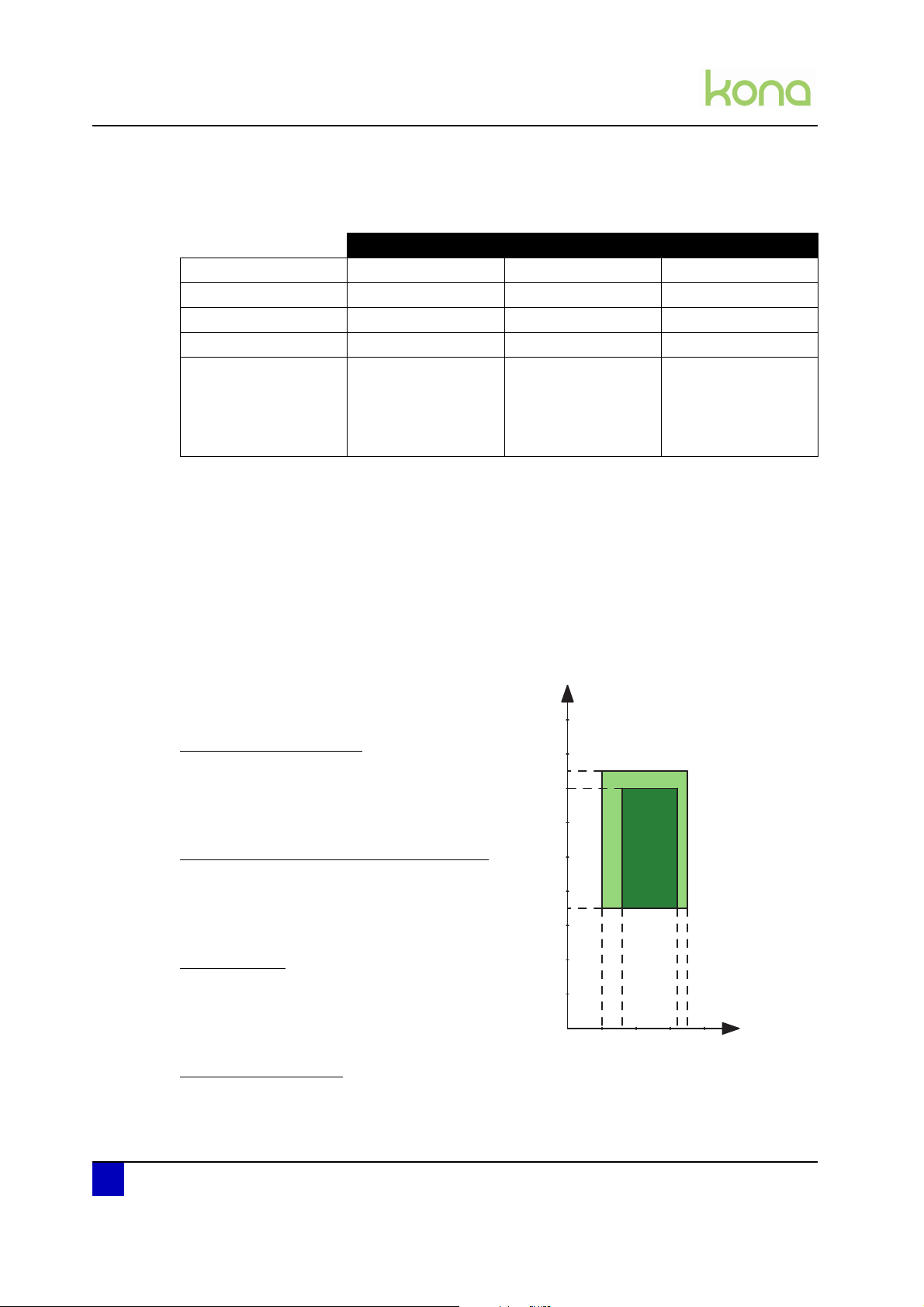
2.2 Installation environment requirements
2.2.1 Power supply
Voltage 100-240 V AC
Current 1,5 A
Frequency 50-60 Hz
2.2.2 Ambient conditions
Operation environment
Temperature: 10°C - 35°C
Humidity: 35% - 75% non-condensing
Recommended environment (dark area)
Temperature: 16°C - 32°C
Humidity: 35% - 70% non-condensing
Variation rate
Temperature: 2°C per hour
Humidity: 5% per hour
T(°C)
Storage environment
Temperature: 0°C - 50°C
14 AP-74380 - Revision 1.1
Page 15
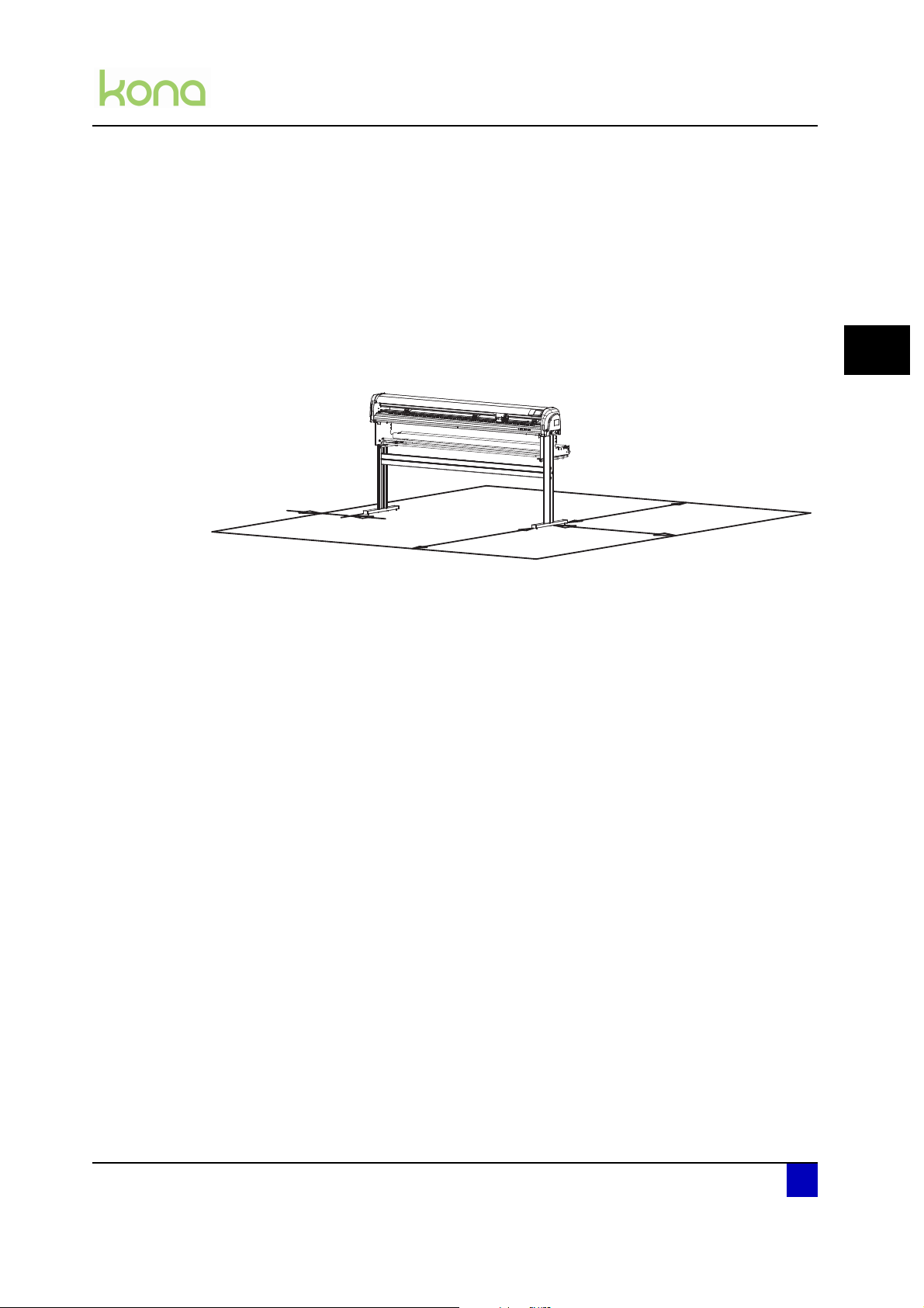
2.2.3 Room conditions
a
b
c
d
Please protect your cutter from moisture, dust, draughts and direct sunlight (to prevent
possible media detection and epos readout issues). It is best to keep your machine away
from open windows and air-conditioners.
See to it that there is an adequate space around the cutter so that ventilation is not
obstructed.
Avoid unnecessary vibrations and set up your cutter on a level surface.
Be sure to have some free space on each side of the Kona to ease the operating of it.
Service manual Kona cutting plotter
Product overview
2
a = at least 1 meter
b = at least 1 meter
c = at least 1 meter
d = at least 0,2 meter
AP-74380 - Revision 1.1 15
Page 16

Service manual Kona cutting plotter
Product overview
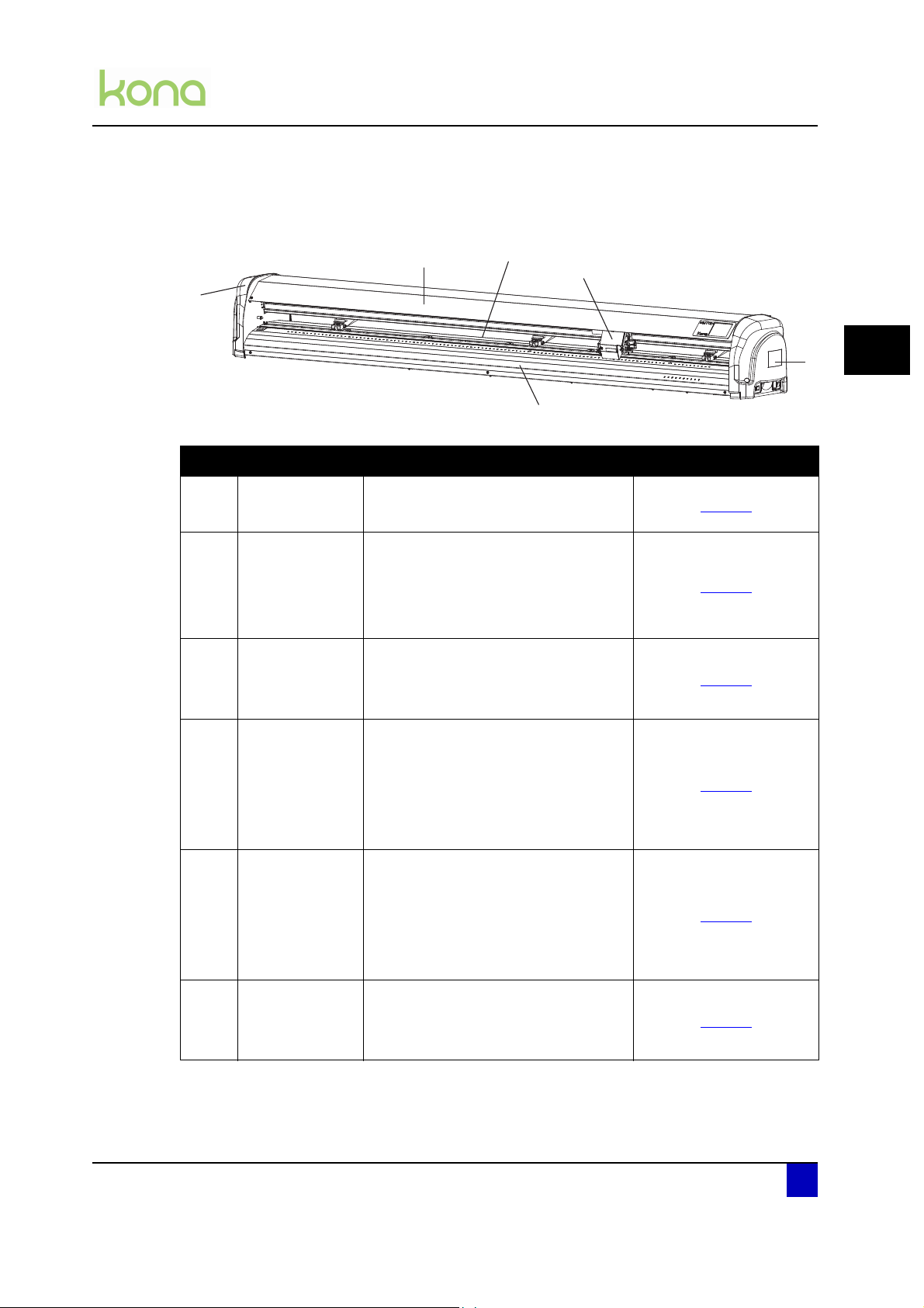
2.3 Part names and functions
N° Description Extended description
1 Pressure rollers To push the media against the grit rollers
2 Media guide
3 Cutting mat
4 Grit rollers
5 Control panel touch screen To make various settings before and during cutting
6 Cutting head
7 USB inlet To connect the USB cable
8 Power inlet and power switch To connect the power cable and power on the unit
9 Roll conveyor To support and roll-off the vinyl
10 Stand and wheels To move the cutter easily
11 Media bag To collect the media when sheeting off
12 Roll-off system To roll-off pre printed vinyl
A guiding platform with vacuum fans to transport
the media as flat as possible during cutting
Provides a reliable cutting surface and minimizes
damage to the knife tip
Rollers with a granular surface to move the media
front and backwards
Assembly of cutting knife, sheet-off mechanism and
EPOS sensor
13 Pressure roller lever To lower and raise the pressure rollers
16 AP-74380 - Revision 1.1
Page 17
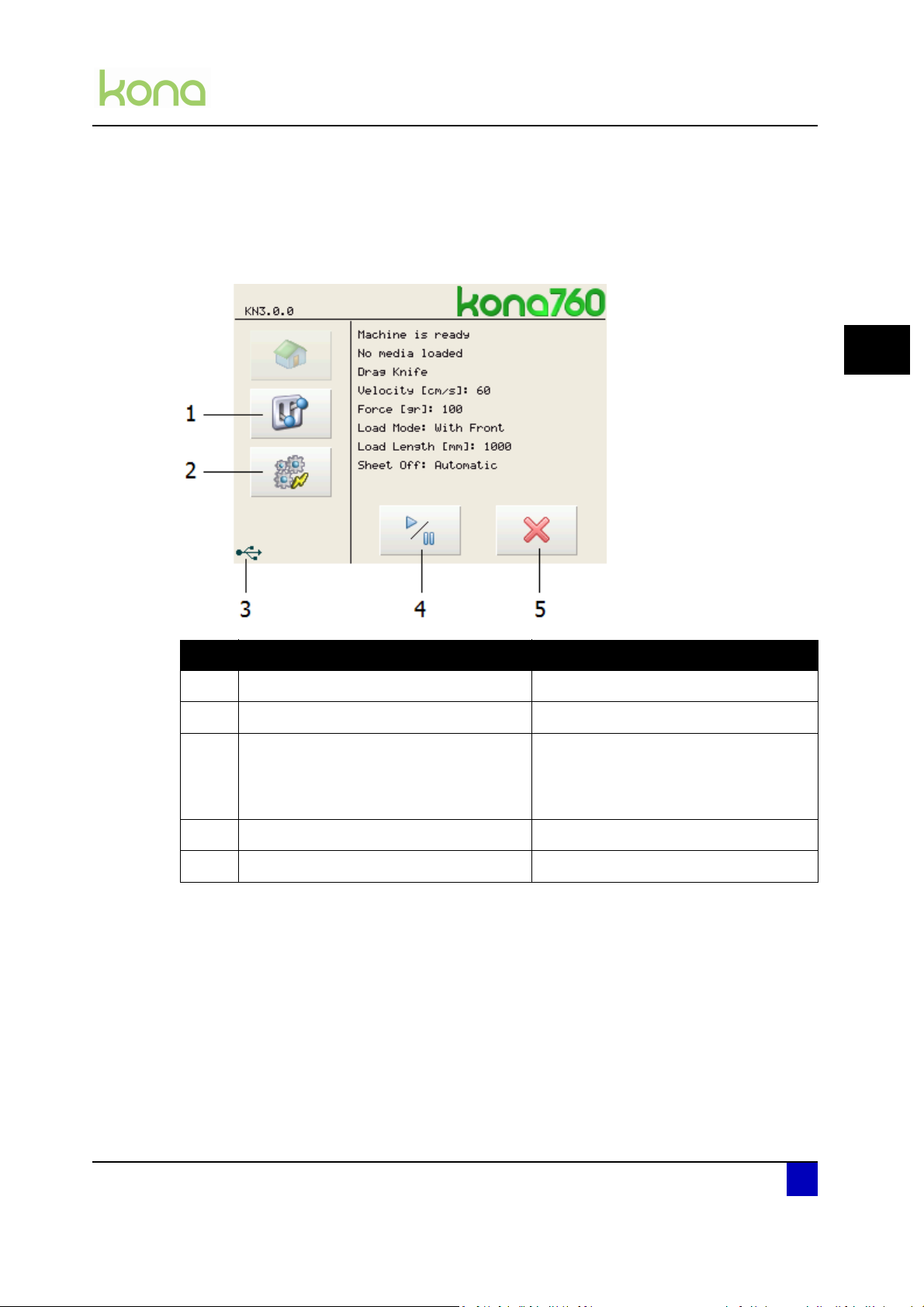
2.4 Overview operation panel
2.4.1 Main menu
Service manual Kona cutting plotter
Product overview
2
N° Description Extended description
1 Settings button Open the settings menu 1/4
2 Actions button Open the actions menu 1/2
This icon will appear as from the
3 USB indication
4 Play / pause button Pause or resume a job
5 Cancel button Cancel a job
moment the Kona is connected via USB
to the computer AND the correct drivers
are installed.
AP-74380 - Revision 1.1 17
Page 18
Service manual Kona cutting plotter
Product overview
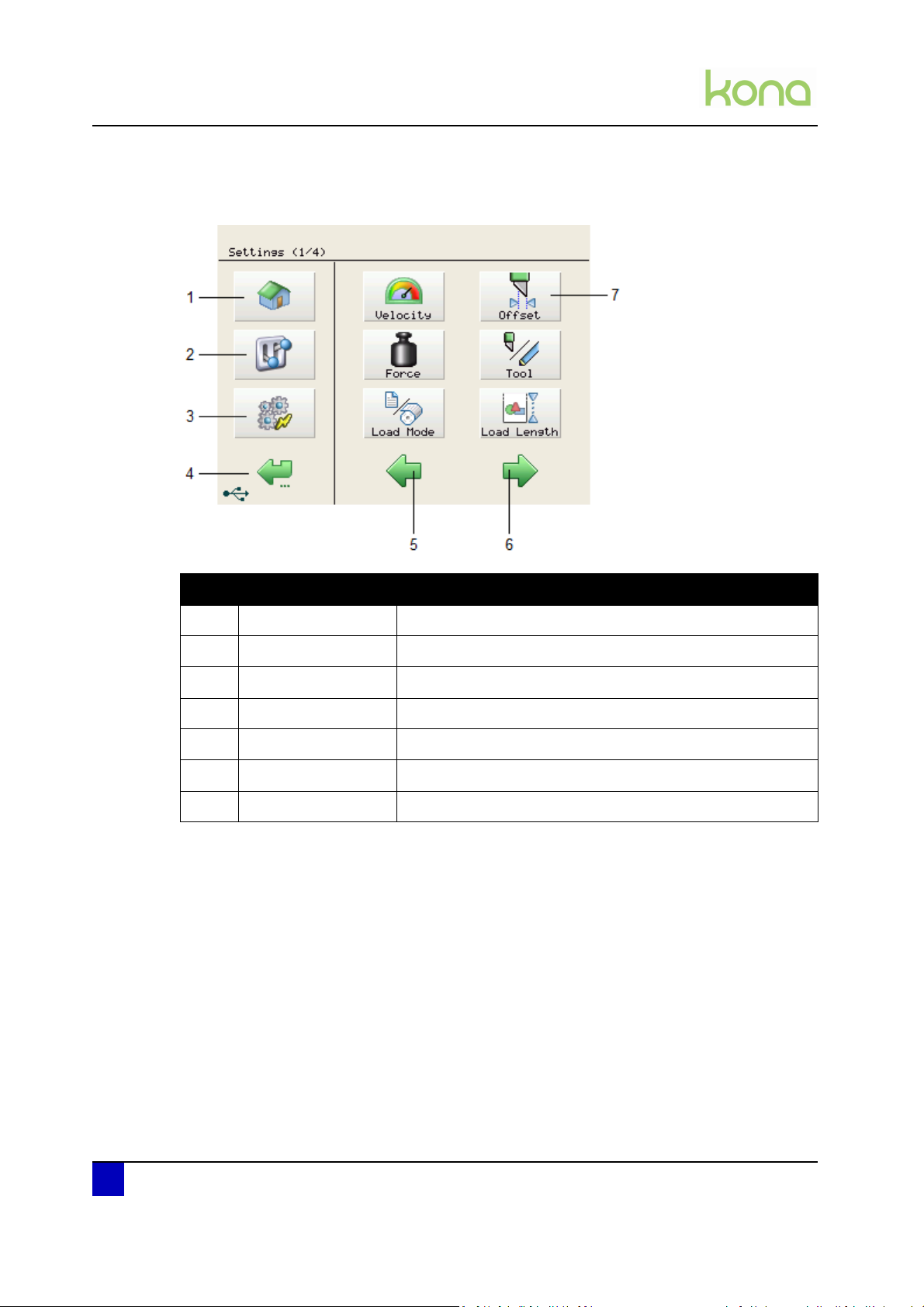
2.4.2 Settings or actions menu
N° Description Extended description
1 Home button Go back to the home menu (the menu shown above)
2 Settings button Open the settings menu 1/4
3 Actions button Open the actions menu 1/2
4 Back / cancel button Go back to the previous menu in the hierarchy
5 Previous button Go back to the previous page within a menu level
6 Next button Go to the next menu page within a menu level
7 Menu button Open the respective menu
18 AP-74380 - Revision 1.1
Page 19

2.4.3 Adjust value menu
Service manual Kona cutting plotter
Product overview
2
N° Description Extended description
1 Home button Go back to the home menu (the menu shown above)
2 Settings button Open the settings menu 1/4
3 Actions button Open the actions menu 1/2
4 Back / cancel button
5 Numeric keyboard Type the requested set value
6 Save button Save the new value
7 Decrease button Decrease the value with one digit
8 Increase button Increase the value with one digit
9 Erase button Delete the last digit
10 Erase all button Erase the complete value
Go back to the previous menu in the hierarchy and/or cancel
the settings change
Note
It is impossible to exceed a maximum value. The cutter will beep twice if you
try.
The value will be displayed in blue when the chosen value is smaller than the
minimum value.
AP-74380 - Revision 1.1 19
Page 20
Service manual Kona cutting plotter
Product overview
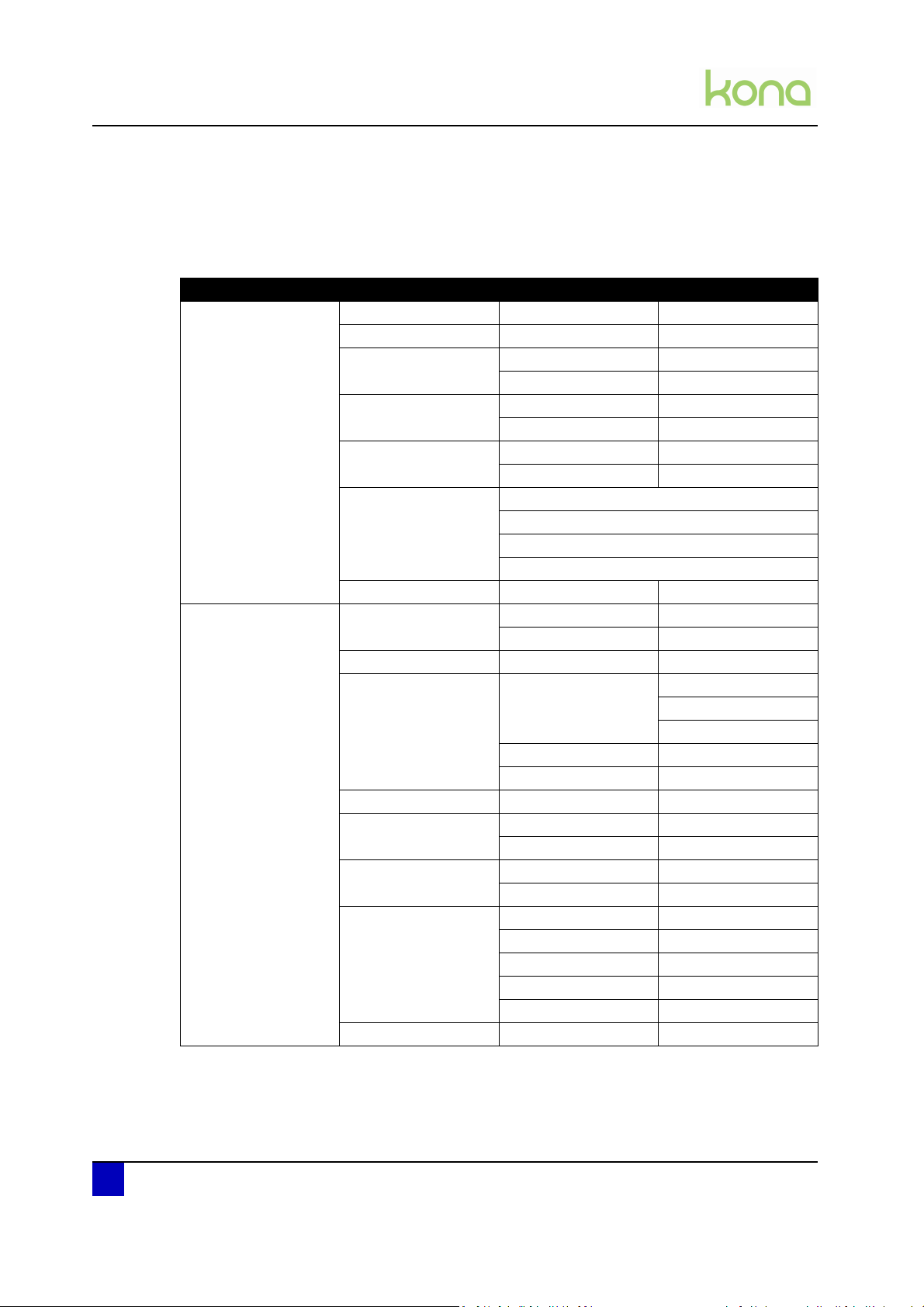
2.5 Menu overview
2.5.1 User mode
Main menu Sub menus BOLD = default value
Settings 1/4 Velocity Tool down 1 - 60 -100 cm/s
Offset Offset 0.1 - 0.5 - 1 mm
Force Force 20 - 100 - 450 g
To ol Drag knife
Load mode With front
Load Length 100 - 1000 - 10000 mm
Settings 2/4 Smoothing On
Prefeed 0 - 1000 - 10000 mm
Sheet off Mode Automatic
Max. length 0 - 2000 - 10000
Job Focus Accuracy
Auto shuffle On
Origin Center
Page Mode 0 - 1 - 2
Tool up 1 - 100 cm/s
Te st
Te st
Pen
Without front, uneven media
With front, uneven media
Without front
Off
Manual
Disabled
Margin 1 - 5 - 250 mm
Velocity 10 - 60 - 100 cm/s
Speed
Off
Lower right
Lower left
Upper right
Upper left
20 AP-74380 - Revision 1.1
Page 21

Service manual Kona cutting plotter
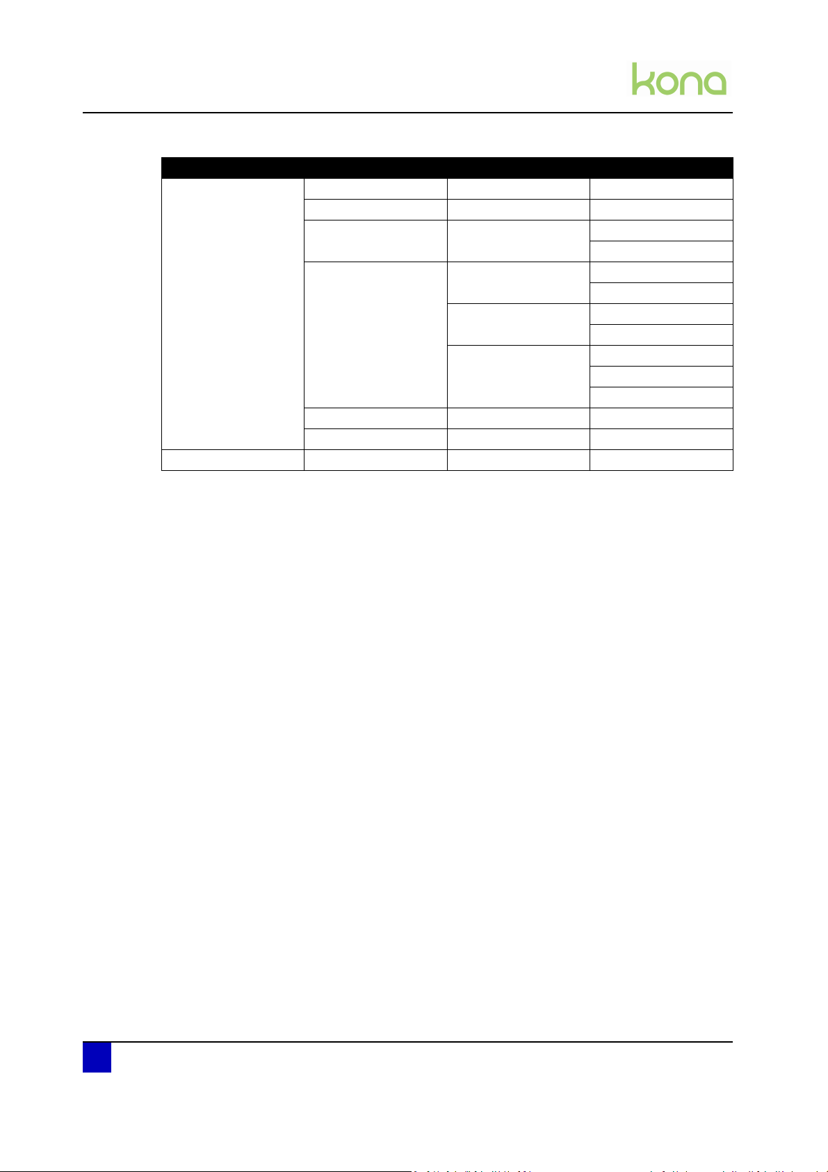
Product overview
Main menu Sub menus BOLD = default value
Settings 3/4 Epos Alignment Automatic
Manual
Language English
Greek
Polski
Portugues
Italiano
Espanol
Deutsch
Francais
Nederlands
Protocol Emulation HPGL2
HPGL
MHGL2
MHGL
VS/ZF/AS Accept
Ignore
Resolution 0.010 mm
0.025 mm
Swap Alert Singletool / multitool
Cut Through Velocity 1 - 15 - 100 cm/s
Force 20 - 250 - 450 g
Te st
Up Distance 0.1 - 2.0 mm
Down Distance 0 - 10 - 100 mm
Epos Alignment Automatic
Manual
Settings 4/4 Diagnostics
Screen Beep Off
Defaults Yes / No
Information Firmware
User
Refer to Diagnostics mode 1 and 2 on page23
On
Contrast 0 - 25 - 40%
Brightness 0 - 50 - 100%
Animation Wait Time
Play
Machine
Company
2
AP-74380 - Revision 1.1 21
Page 22
Service manual Kona cutting plotter
Product overview
Main menu Sub menus BOLD = default value
Actions 1/2 Jogging
Actions 2/2 Copies 0 - 1 - 100
Origin
Cut Through Trim poster Length
Width
Contour Cut Multi frame Single scan
Repeat mode
Single frame Single scan
Repeat mode
Manual Length
Width
Direction
EPOS Read
Sheet-off Yes / No
22 AP-74380 - Revision 1.1
Page 23
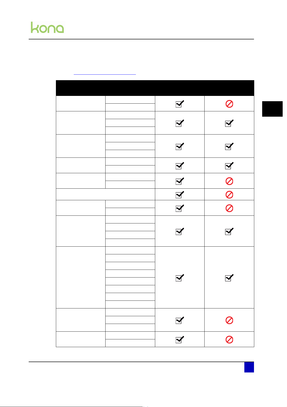
2.5.2 Diagnostics mode 1 and 2
Refer to Diagnostics mode on page105 for further details.
Connection
Encoder
PWM test
Defaults
Accuracy
Machine
X
Y
X
Y
Z
X
Y
Z
User
X
Y
Service manual Kona cutting plotter
Product overview
Availability
Diagnostics 1 Diagnostics 2
2
Too l Fo rc e
Actuators
Sensors
Aging
Screen
YZ profile
Measure
Verify
Laser
Fan
Buzzer
Leds
Media front left
Media front right
Media rear
Lever
Pinch flap
Dip switches
XY voltage
EPOS
Tool
Sheet off
Cut through
VCM
Touchfield
AP-74380 - Revision 1.1 23
Page 24
Service manual Kona cutting plotter
Product overview
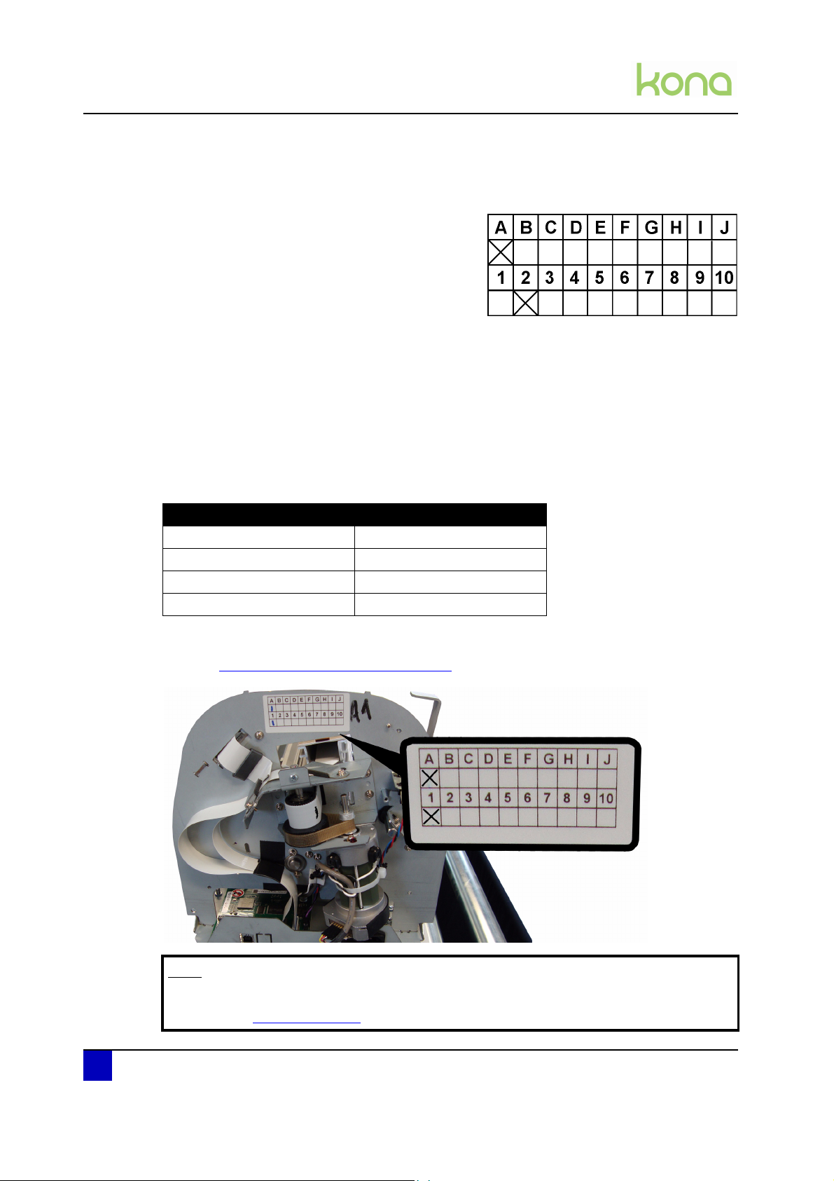
2.6 Machine version
Each machine has its own version number existing
out of a letter (version) and a number (revision),
e.g. A2.
Some parts integrated in a machine with a
higher version number, might not be
downwards-compatible with machines
containing a lower version number.
Example: Parts tagged with version C are NOT downwards compatible with machines
from version A and B
Some parts integrated in a machine with a higher revision number, are downwards
compatible with machines containing a lower revision number.
Parts that are different due to different version-numbers, will be tagged on the sparepart-list,
with a serial number. (refer to the table below)
When spare parts have to be ordered, please always verify the serial-number on the cutter,
with those on the sparepart-list, to ensure you use the correct part!
Serial numbers Machine version number
LA-1909xx A1
LA-1910xx and LA-1911xx A2
LA-1912xx A3
LA-1001xx to LA-1007xx A4
The version label of the machine can be found behind the right side cover.
Refer to Cover removal > Side covers on page 28
Note
The list of differences between the versions can be requested at our service
department (service@mutoh.eu
24 AP-74380 - Revision 1.1
).
Page 25

Service manual Kona cutting plotter
Part replacement
Chapter 3 Part replacement
Important
Before replacing parts, be sure to take the following precautionary measures:
Power OFF the cutter
Unplug the power cable
Disconnect all other cables
Only the parts described in this chapter may be replaced and are available as a
spare part.
Refer to the latest spare part price list and exploded views to find the correct
partnumber and price.
3
Cover removal. . . . . . . . . . . . . . . . . . . . . . . . . . . . . . . . . . . . . . . . . . . . . . . 27
Side covers . . . . . . . . . . . . . . . . . . . . . . . . . . . . . . . . . . . . . . . . . . . . . . . . . . . 28
Y-rail cover. . . . . . . . . . . . . . . . . . . . . . . . . . . . . . . . . . . . . . . . . . . . . . . . . . . . 29
Penhead cover. . . . . . . . . . . . . . . . . . . . . . . . . . . . . . . . . . . . . . . . . . . . . . . . . 30
Front platen . . . . . . . . . . . . . . . . . . . . . . . . . . . . . . . . . . . . . . . . . . . . . . . . . . . 31
Rear platen . . . . . . . . . . . . . . . . . . . . . . . . . . . . . . . . . . . . . . . . . . . . . . . . . . . 32
X-motor and drive belt . . . . . . . . . . . . . . . . . . . . . . . . . . . . . . . . . . . . . . . . 33
Y-motor assembly . . . . . . . . . . . . . . . . . . . . . . . . . . . . . . . . . . . . . . . . . . . 35
Exploded view . . . . . . . . . . . . . . . . . . . . . . . . . . . . . . . . . . . . . . . . . . . . . . . . . 35
Y-motor . . . . . . . . . . . . . . . . . . . . . . . . . . . . . . . . . . . . . . . . . . . . . . . . . . . . . . 36
Y-drive pulley and speed reduction belt. . . . . . . . . . . . . . . . . . . . . . . . . . . . . . 38
Y-return pulley . . . . . . . . . . . . . . . . . . . . . . . . . . . . . . . . . . . . . . . . . . . . . . . . . 39
Penhead assembly . . . . . . . . . . . . . . . . . . . . . . . . . . . . . . . . . . . . . . . . . . . 40
Exploded view . . . . . . . . . . . . . . . . . . . . . . . . . . . . . . . . . . . . . . . . . . . . . . . . . 40
Penhead FFC (flexible flat cable). . . . . . . . . . . . . . . . . . . . . . . . . . . . . . . . . . . 41
Penhead assembly . . . . . . . . . . . . . . . . . . . . . . . . . . . . . . . . . . . . . . . . . . . . . 44
Penhead drive belt. . . . . . . . . . . . . . . . . . . . . . . . . . . . . . . . . . . . . . . . . . . . . . 47
Sheet-off mechanism . . . . . . . . . . . . . . . . . . . . . . . . . . . . . . . . . . . . . . . . . . . . 49
EPOS sensor block . . . . . . . . . . . . . . . . . . . . . . . . . . . . . . . . . . . . . . . . . . . . . 50
Y-origin flex PCB . . . . . . . . . . . . . . . . . . . . . . . . . . . . . . . . . . . . . . . . . . . . . . . 52
AP-74380 - Revision 1.1 25
Page 26

Service manual Kona cutting plotter
Part replacement
Grit shaft . . . . . . . . . . . . . . . . . . . . . . . . . . . . . . . . . . . . . . . . . . . . . . . . . . . 53
Exploded view . . . . . . . . . . . . . . . . . . . . . . . . . . . . . . . . . . . . . . . . . . . . . . . . . 53
Grit shaft and support rollers . . . . . . . . . . . . . . . . . . . . . . . . . . . . . . . . . . . . . . 54
Pressure roller assembly. . . . . . . . . . . . . . . . . . . . . . . . . . . . . . . . . . . . . . 59
Exploded view . . . . . . . . . . . . . . . . . . . . . . . . . . . . . . . . . . . . . . . . . . . . . . . . . 59
Pressure roller . . . . . . . . . . . . . . . . . . . . . . . . . . . . . . . . . . . . . . . . . . . . . . . . . 60
Pressure roller assembly . . . . . . . . . . . . . . . . . . . . . . . . . . . . . . . . . . . . . . . . . 61
Cutting mat . . . . . . . . . . . . . . . . . . . . . . . . . . . . . . . . . . . . . . . . . . . . . . . . . 66
Electronics . . . . . . . . . . . . . . . . . . . . . . . . . . . . . . . . . . . . . . . . . . . . . . . . . 67
Mainboard . . . . . . . . . . . . . . . . . . . . . . . . . . . . . . . . . . . . . . . . . . . . . . . . . . . . 67
X and Y motor fuse . . . . . . . . . . . . . . . . . . . . . . . . . . . . . . . . . . . . . . . . . . . . . 74
Penhead PCB . . . . . . . . . . . . . . . . . . . . . . . . . . . . . . . . . . . . . . . . . . . . . . . . . 75
Power supply . . . . . . . . . . . . . . . . . . . . . . . . . . . . . . . . . . . . . . . . . . . . . . . . . . 78
Touchscreen . . . . . . . . . . . . . . . . . . . . . . . . . . . . . . . . . . . . . . . . . . . . . . . . . . 80
Sensors . . . . . . . . . . . . . . . . . . . . . . . . . . . . . . . . . . . . . . . . . . . . . . . . . . . . . . 81
Vacuum fans . . . . . . . . . . . . . . . . . . . . . . . . . . . . . . . . . . . . . . . . . . . . . . . . . . 83
26 AP-74380 - Revision 1.1
Page 27
3.1 Cover removal
1
2
3
4
5
6
N° Description Get access to the following parts Removal procedure
Service manual Kona cutting plotter
Part replacement
3
1
Left cover
2
Y-rail cover
3
Rear platen
4
Penhead cover
5
Right cover
Belt return pulley assy
Grit shaft drive pulley and belt
Penhead assembly
Head FFC (flex flat cable)
Pressure roller assembly
Touchscreen assembly
Rear paper sensor
Power supply
X-motor assembly
EPOS block
Sheet-off assembly
Penhead assembly
Penhead board
Y-origin flex PCB
Y-motor assembly
Speed reduction pulley
Pressure roller up/down sensor
Mainboard flatcables
Power inlet
page 28
page 29
page 32
page 30
page 28
6
Front platen
AP-74380 - Revision 1.1 27
Paper front sensors (2)
Mainboard
X-motor connector
page 28
Page 28
Service manual Kona cutting plotter
2x
Part replacement
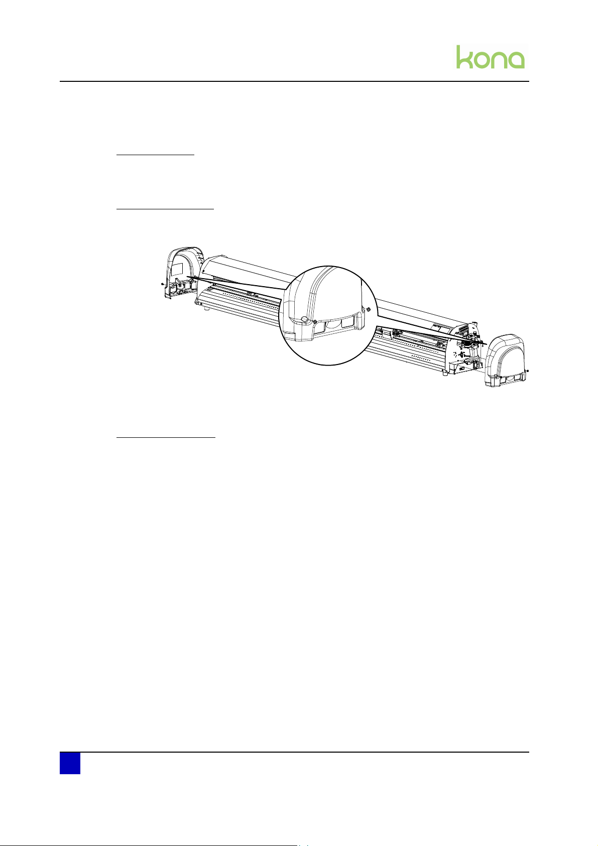
3.1.1 Side covers
Tools necessary
P2 screwdriver
Removal procedure
Step 1: Remove the 2 screws fixing the side cover.
Step 2: Hook off the side covers.
Reassembling notes
When reinstalling the cover, hook it over the positioning points of the side frame.
28 AP-74380 - Revision 1.1
Page 29

3.1.2 Y-rail cover
4x
Tools necessary
P2 screwdriver
Removal procedure
Service manual Kona cutting plotter
Part replacement
Step 1: Remove on of the side covers first.
Refer to Cover removal > Side covers on page 28
Step 2: Loosen the 4 screws fixing the Y-rail cover.
Step 3: Remove the Y-rail cover.
3
AP-74380 - Revision 1.1 29
Page 30
Service manual Kona cutting plotter
3x
Part replacement
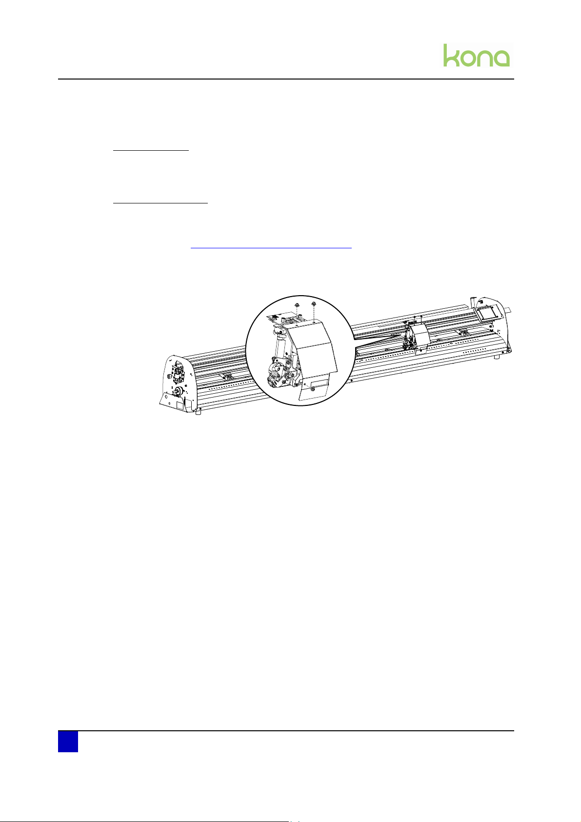
3.1.3 Penhead cover
Tools necessary
P2 screwdriver
Removal procedure
Step 1: Remove side covers and Y-rail cover first
Refer to Cover removal > Y-rail cover on page 29
Step 2: Remove the 3 screws fixing the penhead cover.
Step 3: Remove the penhead cover.
30 AP-74380 - Revision 1.1
Page 31

3.1.4 Front platen
3x
Tools necessary
P2 screwdriver
Removal procedure
Service manual Kona cutting plotter
Part replacement
Step 1: Remove the side covers, Y-rail cover and penhead cover.
Refer to Cover removal > on page 27
Step 2: Remove the 3 screws fixing the front platen.
Step 3: Loosen the screw at the left and right side pushing down the front platen.
3
Step 4: Remove the front platen carefully. It might be necessary to move the penhead
during removal.
Reassembling notes
Step 1: Position the head in the middle of the print platform.
Step 2: Hook the front platen over the front sensors.
Step 3: Push the plate back in its original position and tighten the screws at the front and
then sides.
AP-74380 - Revision 1.1 31
Page 32

Service manual Kona cutting plotter
Part replacement
3.1.5 Rear platen
Tools necessary
P2 screwdriver
Removal procedure
Step 1: Remove the following covers first:
Side covers
Refer to Cover removal > Side covers on page 28
Y-rail cover
Refer to Cover removal > Y-rail cover on page 29
Step 2: Remove the 3 screws fixing the rear platen.
3x
Step 3: Lower the pressure rollers.
Step 4: Remove the rear platen.
32 AP-74380 - Revision 1.1
Page 33

3.2 X-motor and drive belt
Tools necessary
P2 screwdriver
Replacement procedure
Service manual Kona cutting plotter
Part replacement
Follow the procedure below to replace the X-motor and/or drive belt.
Step 1: Remove the following covers first:
Left cover
Refer to Cover removal > Side covers on page 28
Front platen
Refer to Cover removal > Front platen on page 31
Rear platen
Refer to Cover removal > Rear platen on page 32
Step 2: Remove the 2 screws fixing the X-motor assembly.
Step 3: Disconnect the cable at the front side of the cutter.
3
AP-74380 - Revision 1.1 33
Page 34

Service manual Kona cutting plotter
Part replacement
Step 4: Replace the motor and cable.
Step 5: Remove the grounding bracket.
Step 6: Replace the drive belt.
o
Adjustments necessary
After replacing this part, it is necessary to make the following adjustment.
N° Description Link
1 X drive belt tension Mechanical adjustments on page86
34 AP-74380 - Revision 1.1
Page 35

3.3 Y-motor assembly
rear
front
front
rear
1
2
3
4
3.3.1 Exploded view
Service manual Kona cutting plotter
Part replacement
3
N° Description Replacement procedure
1 Y-mo tor page 36
2 Y-drive pulley page 38
3 Speed reduction belt page 39
4 Y-return pulley page 39
AP-74380 - Revision 1.1 35
Page 36

Service manual Kona cutting plotter
Part replacement
3.3.2 Y-motor
Tools necessary
P2 screwdriver
Replacement procedure
Follow the procedure below to replace the Y-motor.
Step 1: Remove the following covers first:
Right cover
Refer to Cover removal > Side covers on page 28
Front platen
Refer to Cover removal > Front platen on page 31
Step 2: Remove the 2 screws fixing the Y-motor.
36 AP-74380 - Revision 1.1
Page 37

Step 3: Disconnect the following cables:
From motor to mainboard
From motor to lever up/down sensor
Step 4: Put the lever in the down position.
Step 5: Gently tilt out and replace the Y-motor.
Service manual Kona cutting plotter
Part replacement
3
Adjustments necessary
After replacing this part, it is necessary to make the following adjustment.
N° Description Link
1 Y drive belt tension Mechanical adjustments on page87
AP-74380 - Revision 1.1 37
Page 38

Service manual Kona cutting plotter
Part replacement
3.3.3 Y-drive pulley and speed reduction belt
Tools necessary
P1 and P2 screwdriver
Replacement procedure
Follow the procedure below to replace the Y-drive pulley and speed reduction belt.
Step 1: Remove all covers except the front and rear platen
Refer to Cover removal on page27
Step 2: Remove the penhead assembly
Refer to Penhead assembly > Penhead assembly on page 44
Step 3: Loosen penhead drive belt
Refer to Penhead assembly > Penhead drive belt on page 47
Step 4: Remove the Y-motor
Refer to Y-motor assembly > Y-motor on page 36
Step 5: Loosen the screw fixing the Y-drive pulley.
Step 6: Replace the Y-drive pulley and/or speed reduction belt.
Adjustments necessary
After replacing this part, it is necessary to make the following adjustment.
N° Description Link
1 Y drive belt tension Mechanical adjustments on page87
2 Penhead drive belt tension Mechanical adjustments on page88
38 AP-74380 - Revision 1.1
Page 39

3.3.4 Y-return pulley
Tools necessary
P2 screwdriver
Replacement procedure
Service manual Kona cutting plotter
Part replacement
Follow the procedure below to replace the Y-return pulley.
Step 1: Remove the following covers first:
Left cover
Refer to Cover removal > Side covers on page 28
Y-rail cover
Step 2: Remove the penhead assembly
Refer to Penhead assembly > Penhead assembly on page 44
Step 3: Loosen penhead drive belt
Refer to Penhead assembly > Penhead drive belt on page 47
Step 4: Loosen the 2 screws fixing the Y-return pulley.
3
Step 5: Turn the Y-return pulley shaft 90 degrees and remove the metal sockets.
Step 6: Remove and replace the Y-return pulley.
Adjustments necessary
After replacing this part, it is necessary to make the following adjustment.
N° Description Link
1 Penhead drive belt tension Mechanical adjustments on page88
AP-74380 - Revision 1.1 39
Page 40

Service manual Kona cutting plotter
1
2
3
4
5
6
Part replacement
3.4 Penhead assembly
3.4.1 Exploded view
N° Description Replacement procedure
1 Penhead FFC (flexible flat cable) page 41
2 Penhead PCB page 75
3 Penhead drive belt page 47
4 Sheet-off mechanism page 49
5 EPOS sensor block page 50
40 AP-74380 - Revision 1.1
6 Y-origin flex PCB page 52
Page 41

3.4.2 Penhead FFC (flexible flat cable)
Tools necessary
P2 screwdriver
Snap-off blade
Service manual Kona cutting plotter
Part replacement
Replacement procedure
Follow the procedure below to replace the penhead FFC.
Step 1: Remove the following covers first:
Right cover
Refer to Cover removal > Side covers on page 28
Y-rail cover
Refer to Cover removal > Y-rail cover on page 29
Penhead cover
Refer to Cover removal > Penhead cover on page 30
Step 2: Remove the 2 screws of the flatcable bracket.
3
Step 3: Disconnect the flatcable.
AP-74380 - Revision 1.1 41
Page 42

Service manual Kona cutting plotter
Part replacement
Step 4: Carefully loosen the flatcable guider (only for Kona 1400 and 1650). Be careful not
to bend the guider and to cut in the flatcable!
Step 5: Loosen the 2 brackets fixing the flatcable at the right side of the cutter.
Step 6: Unplug the flatcable from the mainboard and replace it.
42 AP-74380 - Revision 1.1
Page 43

Service manual Kona cutting plotter
Part replacement
Reassembling notes
Step 1: Move the penhead to the far left of the machine and press it against the pen until the
sheet-off knife is pushed out completely.
Step 2: Mount the flatcable to the penhead PCB and fix the flatcable bracket.
Step 3: Start guiding the flatcable in the gutter until you reach the middle (where no double
sided tape is installed).
Step 4: Adjust the flatcable position until it does not interfere with the Y-return pulley
bracket. If you do not install the flatcable correctly, it might be damaged during
cutting.
3
Step 5: Guide the flatcable through the cutter to the right side.
Step 6: Stick the flatcable onto the double side tape.
Step 7: Bend the flatcable in an angle of 90° and fix the flatcable bracket as shown below:
Step 8: Plug the flatcable in the mainboard. Be sure the flatcable is installed rectangularly.
AP-74380 - Revision 1.1 43
Page 44

Service manual Kona cutting plotter
Part replacement
3.4.3 Penhead assembly
Tools necessary
P2 screwdriver
Hexagon wrench 5,5 mm
Hexagon key 2,5 mm
Replacement procedure
Follow the procedure below to remove the penhead assembly.
Step 1: Remove the following covers first:
Step 2: Remove the following covers first
Side covers
Y-rail cover
Penhead cover
Refer to Cover removal on page27
Step 3: Disconnect the 3 flex cables.
Step 4: Loosen the two hexagon spacers.
Step 5: Move the penhead to the middle of the machine.
44 AP-74380 - Revision 1.1
Page 45

Service manual Kona cutting plotter
Step 6: Remove the screw fixing the penhead to the drive belt.
Step 7: Remove the screw on top of the penhead.
Part replacement
3
Step 8: Remove the leaf spring.
Step 9: Remove penhead assembly by tilting it of the Y-rail.
AP-74380 - Revision 1.1 45
Page 46

Service manual Kona cutting plotter
Part replacement
Adjustments necessary
After replacing/removing this part, it is necessary to make the following adjustment.
N° Description Link
1 EPOS calibration EPOS calibration on page103
2 YZ profile YZ measurement on page93
Reassembling notes
Pay attention to the order of the installation of the leaf spring, washer and screw.
Step 1: Install the leaf spring.
Step 2: Install the washer.
Step 3: Tighten the screw.
46 AP-74380 - Revision 1.1
Page 47

3.4.4 Penhead drive belt
Tools necessary
P2 screwdriver
Hexagon wrench 5,5 mm
Hexagon key 2,5 mm
Service manual Kona cutting plotter
Part replacement
Replacement procedure
Follow the procedures below to replace the penhead drive belt.
Step 1: Remove the following covers first
Side covers
Y-rail cover
Penhead cover
Refer to Cover removal on page27
Step 2: Remove the penhead assembly
Refer to Penhead assembly > Penhead assembly on page 44
Step 3: Loosen the 2 screws fixing the Y-return pulley equally. This will ease the adjustment
of the penhead drive belt afterwards.
3
Step 4: Turn the Y-return pulley shaft 90 degrees.
AP-74380 - Revision 1.1 47
Page 48

Service manual Kona cutting plotter
Part replacement
Step 5: Remove the 4 screws of the drive belt connection plate.
Step 6: Replace the penhead drive belt.
Adjustments necessary
After replacing this part, it is necessary to make the following adjustment.
N° Description Link
1 Penhead drive belt tension Mechanical adjustments on page88
2 EPOS calibration EPOS calibration on page103
48 AP-74380 - Revision 1.1
Page 49

3.4.5 Sheet-off mechanism
Tools necessary
P2 screwdriver
Replacement procedure
Service manual Kona cutting plotter
Part replacement
Step 1: Remove the 2 screws fixing the sheet-off mechanism.
Step 2: Replace the sheet-off mechanism.
Refer to the User’s Guide to know how to replace the sheet-off blade only.
Adjustments necessary
After replacing this part, it is necessary to make the following adjustment.
3
N° Description Link
1 Sheet-off knife position Mechanical adjustments on page91
AP-74380 - Revision 1.1 49
Page 50

Service manual Kona cutting plotter
Part replacement
3.4.6 EPOS sensor block
Tools necessary
P2 screwdriver
Replacement procedure
Follow the procedure below to replace the EPOS sensor block.
Step 1: Remove the following covers first:
Step 2: Remove the following covers first
Side covers
Y-rail cover
Penhead cover
Refer to Cover removal on page27
Step 3: Disconnect the EPOS sensor flatcable from the PCB board.
50 AP-74380 - Revision 1.1
Page 51

Step 4: Remove the screw fixing the EPOS sensor block.
Service manual Kona cutting plotter
Part replacement
3
Step 5: Replace the EPOS sensor block.
Adjustments necessary
After replacing this part, it is necessary to make the following adjustment.
N° Description Link
1 EPOS calibration EPOS calibration on page103
AP-74380 - Revision 1.1 51
Page 52

Service manual Kona cutting plotter
Part replacement
3.4.7 Y-origin flex PCB
Tools necessary
P2 screwdriver
Hexagon wrench 5,5 mm
Hexagon key 2,5 mm
Replacement procedure
Follow the procedure below to replace the Y-origin flex PCB.
Step 1: Remove the following covers first
Side covers
Y-rail cover
Penhead cover
Refer to Cover removal on page27
Step 2: Remove the penhead assembly.
Refer to Penhead assembly > Penhead assembly on page 44
Step 3: Loosen the 2 screws fixing the Y-origin flex PCB.
Step 4: Replace the Y-origin flex PCB.
Adjustments necessary
After replacing this part, it is necessary to make the following adjustment.
N° Description Link
1 EPOS calibration EPOS calibration on page103
52 AP-74380 - Revision 1.1
Page 53

3.5 Grit shaft
1
2
3
3.5.1 Exploded view
Service manual Kona cutting plotter
Part replacement
3
N° Description Replacement procedure
1 Grit shaft page 54
2 Grit shaft bearings page 54
3 Grit shaft support rolls page 58
AP-74380 - Revision 1.1 53
Page 54

Service manual Kona cutting plotter
Part replacement
3.5.2 Grit shaft and support rollers
Tools necessary
Paper sheets (A5 - A4)
Tape
P2 screwdriver
Hexagon key 1,5 mm
Loctite 641
Hammer
Replacement procedure
Follow the procedure below to replace the grit shaft and support rollers.
Step 1: Remove all the covers of the cutter
Refer to Cover removal on page27
Step 2: Be sure that the lever is in the UP position.
Step 3: Loosen the screws of the X-motor.
Step 4: Remove the screw fixing the grounding bracket
54 AP-74380 - Revision 1.1
Page 55

Service manual Kona cutting plotter
Part replacement
Step 5: Install a piece of paper between the grit shaft and each support roll assembly to
avoid damaging them when pulling out the shaft later on.
Step 6: Loosen the 2 setscrews of the speed reduction pulley.
3
Step 7: Remove the speed reduction pulley and white spacer.
Step 8: Remove the 2 screws fixing the left bearing of the grit roll shaft.
AP-74380 - Revision 1.1 55
Page 56

Service manual Kona cutting plotter
Part replacement
Step 9: Hammer out the grit shaft from the right side of the machine until the bearing at the
left comes out.
Step 10: Remove the grit shaft assembly.
Step 11: Remove the 2 screws fixing the right bearing of the grit roll shaft.
Step 12: Remove the bearing at the right side of the cutter.
Step 13: Remove all screws fixing a grit shaft support roll and remove them.
56 AP-74380 - Revision 1.1
Page 57

Service manual Kona cutting plotter
!
!
Left Right
Part replacement
Reassembling notes
1. The grit shaft support rolls can be mounted in two ways (as shown below). Be sure to
install them correctly. With the large collar of the bearing facing the screw.
3
2. When replacing the grit shaft, you will have to order a kit including the following items:
Grit shaft
2 bearings
A set of grit shaft support rolls (quantity depends on the machine size)
3. Reinstall the grit shaft as follows:
Step 1: Clean both ends of the grit shaft with isopropanol and let it dry completely!
Step 2: Clean the inside of the bearings with isopropanol and let it dry completely!
Step 3: Apply loctite 641 on the left side of the grit shaft. (refer to the picture above)
AP-74380 - Revision 1.1 57
Page 58

Service manual Kona cutting plotter
Part replacement
Step 4: Install a bearing and push it as far as possible.
Step 5: Remove the spoiled glue.
Step 6: Install the grit shaft from left to right. Be careful not to damage the grit sections when
moving it through the hole in the left end plate.
Step 7: Apply loctite 641 on the right side of the grit shaft and install the right bearing.
Step 8: Fix the bearings with each two screws.
Step 9: Remove the spoiled glue on the inside
Step 10: Reinstall all parts previously removed in reverse order.
Adjustments necessary
After replacing this part, it is necessary to make the following adjustment.
N° Description Link
1 X drive belt tension Mechanical adjustments on page86
58 AP-74380 - Revision 1.1
Page 59

3.6 Pressure roller assembly
1
2
3.6.1 Exploded view
Service manual Kona cutting plotter
Part replacement
3
N° Description Replacement procedure
1 Pressure roller assembly page 61
2 Pressure roller page 60
AP-74380 - Revision 1.1 59
Page 60

Service manual Kona cutting plotter
Part replacement
3.6.2 Pressure roller
Tools necessary
Small screwdriver
Replacement procedure
Follow the procedure below to replace the pressure roller.
Step 1: Be sure that the pressure rollers raised.
Step 2: Push on the pressure roller shaft (left and right) until the pressure roller clicks out of
its base.
Step 3: Push down the pressure roller at the back of the machine and remove the roller with
a screwdriver.
60 AP-74380 - Revision 1.1
Page 61

3.6.3 Pressure roller assembly
Tools necessary
P1 and P2 screwdriver
Hexagon wrench 5,5 mm
Hexagon key 2,5 mm
Service manual Kona cutting plotter
Part replacement
Replacement procedure
Follow the procedure below to replace the pressure roller assembly.
Step 1: Remove all the covers of the cutter
Refer to Cover removal on page27
Step 2: Remove the following parts first:
Part Procedure
Penhead Penhead assembly on page44
Penhead drive belt Penhead drive belt on page47
Y-mo tor Y-motor on page36
Speed reduction belt and pulley Y-drive pulley and speed reduction belt on page38
Touchscreen Touchscreen on page80
Step 3: Loosen all flatcable brackets at the right side and unplug the flatcables.
3
Note
Try not to bend the flatcables too much. Frequently folding the cables will
damage them.
AP-74380 - Revision 1.1 61
Page 62

Service manual Kona cutting plotter
Part replacement
Step 4: Remove the hexagon pressure roller shaft as follows:
Put the pressure rollers in the up position.
Remove the shaft stop and spacer (at the left side) by loosening the set screw.
Remove the two screws fixing the pressure roller lever.
Remove the screw fixing the torsion spring (at the right side)
Pay attention to the way the shaft is positioned at this moment. This to know how
to reinstall the shaft after replacing the pressure roller base.
62 AP-74380 - Revision 1.1
Page 63

Step 5: Remove Y-rail as follows:
Support the Y-rail so it can not fall when disassembling it.
Loosen the grounding strip avoiding static electricity on top of the Y-rail.
Service manual Kona cutting plotter
Part replacement
3
Remove the 4 screws fixing the Y-rail at both sides.
Insert the drive belt in the Y-rail.
Tilt out the Y-rail and be careful not to damage the flatcables.
Support the Y-rail when laying it down on a table.
AP-74380 - Revision 1.1 63
Page 64

Service manual Kona cutting plotter
Part replacement
Step 6: Mark the position of the end stop.
Step 7: Loosen the screw fixing the end stop and slide out the stop.
Step 8: Slide out the pressure roller assembly and replace it.
64 AP-74380 - Revision 1.1
Page 65

Service manual Kona cutting plotter
Part replacement
Reassembling notes
Be sure to push the Y-rail to the front against the positioning points on the side frames before
fixing the rail.
3
Be sure to guide and tighten the flatcables in the same way as shown on the picture below:
Adjustments necessary
After replacing this part, it is necessary to make the following adjustment.
N° Description Link
1 EPOS calibration EPOS calibration on page103
2 Penhead drive belt tension Mechanical adjustments on page88
3 Y drive belt tension Mechanical adjustments on page87
4 Pressure roller pressure Mechanical adjustments on page90
AP-74380 - Revision 1.1 65
Page 66

Service manual Kona cutting plotter
Part replacement
3.7 Cutting mat
Tools necessary
Isopropanol
Replacement procedure
Please follow the procedure below to replace the cutting mat.
Step 1: Remove the following covers first
Side covers
Y-rail cover
Penhead cover
Refer to Cover removal on page27
Step 2: Draw a line in front of the cutting mat and remove the worn cutting mat.
Step 3: Clean the platen using isopropanol.
Step 4: Install the new cutting mat in the same position as the previous one.
Step 5: Reinstall the covers.
Adjustments necessary
After replacing this part, it is necessary to make the following adjustment.
N° Description Link
1 YZ calibration YZ measurement on page93
66 AP-74380 - Revision 1.1
Page 67

3.8 Electronics
3.8.1 Mainboard
Tools necessary
P2 screwdriver
Set of pliers
USB cable
Mutoh CutServer and PC
Replacement procedure
Follow the procedure below to replace the mainboard.
Step 1: Store the current parameters using the Mutoh CutServer.
Service manual Kona cutting plotter
Part replacement
3
Refer to Parameters > Backup parameters of machine on page 98
Step 2: Remove the following covers first:
Right cover
Refer to Cover removal > Side covers on page 28
Front platen
Refer to Cover removal > Front platen on page 31
Step 3: Unplug all connectors and flatcables. Note that the touchscreen flatcable has a
special connector. You should push up the lip of the connector before removing it.
AP-74380 - Revision 1.1 67
Page 68

Service manual Kona cutting plotter
Part replacement
Step 4: Remove the 2 screws fixing the mainboard. (only for machine versions A1 and A2)
Refer to Machine version on page24
Step 5: Push in all studs with a set of pliers, remove the mainboard and replace it.
m
Reassembling notes
Follow the procedure below to replace the flatcables correctly.
Step 1: Be sure that the lip of touchscreen flatcable connector is in the up position.
Step 2: Insert the flatcable.
Step 3: Push down the lip of the connector to secure the cable.
Step 4: Also be sure that the flatcables or mounted rectangularly.
68 AP-74380 - Revision 1.1
Page 69

Service manual Kona cutting plotter
Adjustments necessary
After replacing this part, it is necessary to make the following adjustment.
N° Description Link
Uninstall and reinstall USB drivers on
1
the PC
Software and drivers on page96
Part replacement
2 Load firmware Software and drivers on page94
Restore parameters Restore parameters of machine on page99
If there are no parameters available,
either perform the additional
adjustments mentioned below or
contact our service department
3
(service@mutoh.eu
X - Y distance accuracy Mutoh CutServer tests on page102
Y - Z measurement Mechanical adjustments on page93
EPOS calibration EPOS calibration on page103
)
3
AP-74380 - Revision 1.1 69
Page 70

Service manual Kona cutting plotter
Part replacement
Board diagnostics
70 AP-74380 - Revision 1.1
Page 71

Service manual Kona cutting plotter
Connector overview
Connector and function
J1 (+48V) (fans)
J2 (rev A mainboards) or J12 (rev C mainboards) (to headboard)
J3 (to LCD)
J7 (X-motor and encoder)
J8 (Y-motor and encoder)
J9 (Power supply)
J10 (Sensors)
J1 (+48V) (fans)
Pin Pin name
1 + 48V
3GND
Part replacement
3
J2 (rev A mainboards) or J12 (rev C mainboards) (to headboard)
Pin Pin name
1 AI_5V0_EPOS2
2 AI_5V0_EPOS1
3GND
4 +5V0_FIL
5 DO_5V_OUT3
6GND
7IN5
8GND
9 DI_5V0_ENC3B
10 GND
11 DI_5V0_ENC3A
12 GND
13 GND
14 DO_48V_OUT2
15 DO_48V_MOTOR316 DO_48V_MOTOR3+
AP-74380 - Revision 1.1 71
Page 72

Service manual Kona cutting plotter
Part replacement
J7 (X-motor and encoder)
Pin Pin name
1V+
3+5V
4 ENC_A
5V-
7GND
8 ENC_B
J8 (Y-motor and encoder)
Pin Pin name
2V+
3+5V
4 ECN_A
6V-
7GND
8 ENC_B
J9 (Power supply)
Pin Pin name
1+48V
2+48V
3GND
4GND
J10 (Sensors)
Pin Pin name
1+5V0
2 nRear Paper
3GND
4+5V0
5 nFront Paper
6GND
7+5V0
8nMid Paper
9GND
72 AP-74380 - Revision 1.1
Page 73

Pin Pin name
10 +5V0
11 nLever
12 GND
LED summary
LED Function
LD1 G +48 V
LD2 R Error LED 2
LD3 R Error LED 1
LD4 R Error LED 3
LD5 R Error LED 4
LD6 Y Alive
LD14 R X motor (V-)
LD15 R Y motor (V-)
LD16 Y X motor (V+)
LD17 Y Y motor (V+)
Service manual Kona cutting plotter
Part replacement
3
Fuses summary
Connector Function LED
FU1 X Motor
FU2 Y Motor
Switch summary
Switch Function
SW1 RESET
DIP Switch summary
DIP Switch Function
DIP1 -
LD16 Y
LD17 Y
AP-74380 - Revision 1.1 73
Page 74

Service manual Kona cutting plotter
Part replacement
3.8.2 X and Y motor fuse
Tools necessary
P2 screwdriver
Pair of tweezers
Replacement procedure
Follow the procedure below to replace the X or Y motor fuse
Step 1: Remove the following covers first
Side covers
Y-rail cover
Penhead cover
Front platen
Refer to Cover removal on page27
Step 2: Remove the fuse with a pair of tweezer and replace it.
Note
Fuse type
Manufacturer: Littlefuse
Serie: Slo-Blo Fuse 452/454
Partnumber: R452002
2A
74 AP-74380 - Revision 1.1
Page 75

3.8.3 Penhead PCB
Tools necessary
P2 screwdriver
Hexagon wrench 5,5 mm
Service manual Kona cutting plotter
Part replacement
Replacement procedure
Follow the procedure below to replace the penhead PCB.
Step 1: Remove the following covers first:
Side covers
Y-rail cover
Penhead cover
Refer to Cover removal on page27
Step 2: Disconnect the 3 flex cables.
Step 3: Loosen the two hexagon spacers.
3
Step 4: Remove the 2 screws of the flatcable bracket and disconnect the flatcable.
Step 5: Replace the penhead PCB.
AP-74380 - Revision 1.1 75
Page 76

Service manual Kona cutting plotter
Part replacement
Board diagnostics
Connector overview
Connector and function
J1 (to mainboard)
J2 is not used
J3 (EPOS)
J4 (Y-origin)
J5 (PenHead)
J1 (to mainboard)
Pin Pin name
1COIL+
2COIL3 DO_48V_OUT2+
4 DO_48V_OUT25GND
6 CHA
7GND
8 CHB
9GND
10 DI_5V0_IN5
11 GND
12 DO_5V_OUT3
13 +5V0
76 AP-74380 - Revision 1.1
Page 77

Pin Pin name
14 GND
15 AI_5V0_EPOS1
16 AI_5V0_EPOS2
J3 (EPOS)
Pin Pin name
1+5V0
2 AI_5V0_EPOS2
3GND
4 AI_5V0_EPOS1
5GND
6 DO_5V_OUT3
J4 (Y-origin)
Service manual Kona cutting plotter
Part replacement
3
Pin Pin name
1GND
2 nY-Origin
3GND
4+5V
J5 (PenHead)
Pin Pin name
1 CHB
2+5V0
3 CHA
4GND
5GND
6COIL+
7COIL8GND
9GND
10 GND
11 GND
12 GND
AP-74380 - Revision 1.1 77
Page 78

Service manual Kona cutting plotter
Part replacement
3.8.4 Power supply
Important
Be sure to remove the power cable before servicing the power supply!
Tools necessary
P2 screwdriver
Replacement procedure
Follow the procedure below to replace the power supply.
Step 1: Remove the following covers first:
Side covers
Y-rail cover
Penhead cover
Rear platen
Refer to Cover removal on page27
Step 2: Unplug all connectors.
Step 3: Remove the 2 plugs to get access to the 2 rear screws.
78 AP-74380 - Revision 1.1
Page 79

Service manual Kona cutting plotter
Part replacement
Step 4: Depending on the machine version, a protective cover has been installed above the
power supply. Remove it before replacing the power supply.
3
Step 5: Remove the 4 screws fixing the power supply.
Step 6: Replace the power supply.
AP-74380 - Revision 1.1 79
Page 80

Service manual Kona cutting plotter
Part replacement
3.8.5 Touchscreen
Tools necessary
P2 screwdriver
Replacement procedure
Follow the procedure to replace the touchscreen.
Step 1: Remove the following covers first:
Right cover
Refer to Cover removal > Side covers on page 28
Y-rail cover
Refer to Cover removal > Y-rail cover on page 29
Step 2: Remove the screw fixing the touchscreen bracket.
Step 3: Remove the 2 screws fixing the touchscreen plastic cover.
Step 4: Unplug the flat touchscreen data cable.
Step 5: Replace the touchscreen or data cable.
80 AP-74380 - Revision 1.1
Page 81

3.8.6 Sensors
Tools necessary
P2 screwdriver
Pressure roller lever sensor
Service manual Kona cutting plotter
Part replacement
Follow the procedure below to replace the lever sensor.
Step 1: Remove the right cover.
Refer to Cover removal > Side covers on page 28
Step 2: Disconnect the sensor cable.
Step 3: Remove the two screws fixing the sensor bracket.
3
Step 4: Replace the optical U-sensor.
AP-74380 - Revision 1.1 81
Page 82

Service manual Kona cutting plotter
Part replacement
Front and middle paper sensor
Follow the procedure below to replace the front and middle paper sensor.
Step 1: Remove the front platen.
Refer to Cover removal > Front platen on page 31
Step 2: Disconnect the sensor cable.
Step 3: Remove the screw fixing the sensor.
Step 4: Replace the paper sensor.
Rear paper sensor
Follow the procedure below to replace the rear paper sensor.
Step 1: Remove the rear platen.
Refer to Cover removal > Rear platen on page 32
Step 2: Disconnect the sensor cable.
Step 3: Remove the screw fixing the sensor.
Step 4: Replace the paper sensor.
82 AP-74380 - Revision 1.1
Page 83

3.8.7 Vacuum fans
Tools necessary
P2 screwdriver
New cutting mat
Service manual Kona cutting plotter
Part replacement
Replacement procedure
Follow the procedure below to replace the vacuum fans.
Step 1: Remove the following covers first:
Side covers
Y-rail cover
Rear platen
Refer to Cover removal on page27
Step 2: Remove the cutting mat.
Refer to Cutting mat on page66
Step 3: Disconnect the fan cable.
Step 4: Remove the 4 screws fixing the vacuum fan.
3
Step 5: Replace the fan.
Step 6: Install new cutting mat.
Refer to Cutting mat on page66
Adjustments necessary
After replacing this part, it is necessary to make the following adjustment.
N° Description Link
1 YZ calibration YZ measurement on page93
AP-74380 - Revision 1.1 83
Page 84

Service manual Kona cutting plotter
Part replacement
84 AP-74380 - Revision 1.1
Page 85

Service manual Kona cutting plotter
Adjustments and calibrations
Chapter 4 Adjustments and
calibrations
Mechanical adjustments . . . . . . . . . . . . . . . . . . . . . . . . . . . . . . . . . . . . . . 86
X drive belt tension . . . . . . . . . . . . . . . . . . . . . . . . . . . . . . . . . . . . . . . . . . . . . 86
Y drive belt tension . . . . . . . . . . . . . . . . . . . . . . . . . . . . . . . . . . . . . . . . . . . . . 87
Penhead drive belt tension . . . . . . . . . . . . . . . . . . . . . . . . . . . . . . . . . . . . . . . 88
Pressure roller pressure. . . . . . . . . . . . . . . . . . . . . . . . . . . . . . . . . . . . . . . . . . 90
Sheeting-off knife position . . . . . . . . . . . . . . . . . . . . . . . . . . . . . . . . . . . . . . . . 91
YZ measurement . . . . . . . . . . . . . . . . . . . . . . . . . . . . . . . . . . . . . . . . . . . . . . . 93
Software and drivers . . . . . . . . . . . . . . . . . . . . . . . . . . . . . . . . . . . . . . . . . 94
Download latest software and drivers . . . . . . . . . . . . . . . . . . . . . . . . . . . . . . . 94
Firmware installation . . . . . . . . . . . . . . . . . . . . . . . . . . . . . . . . . . . . . . . . . . . . 94
How to uninstall the USB drivers . . . . . . . . . . . . . . . . . . . . . . . . . . . . . . . . . . . 96
How to install the USB drivers . . . . . . . . . . . . . . . . . . . . . . . . . . . . . . . . . . . . . 97
USB icon . . . . . . . . . . . . . . . . . . . . . . . . . . . . . . . . . . . . . . . . . . . . . . . . . . . . . 97
Parameters . . . . . . . . . . . . . . . . . . . . . . . . . . . . . . . . . . . . . . . . . . . . . . . . . 98
Backup parameters of machine . . . . . . . . . . . . . . . . . . . . . . . . . . . . . . . . . . . . 98
Restore parameters of machine. . . . . . . . . . . . . . . . . . . . . . . . . . . . . . . . . . . . 99
4
Mutoh CutServer tests . . . . . . . . . . . . . . . . . . . . . . . . . . . . . . . . . . . . . . . 100
Tracking test . . . . . . . . . . . . . . . . . . . . . . . . . . . . . . . . . . . . . . . . . . . . . . . . . 100
XY-distance accuracy test . . . . . . . . . . . . . . . . . . . . . . . . . . . . . . . . . . . . . . . 102
EPOS calibration . . . . . . . . . . . . . . . . . . . . . . . . . . . . . . . . . . . . . . . . . . . 103
AP-74380 - Revision 1.1 85
Page 86

Service manual Kona cutting plotter
Adjustments and calibrations
4.1 Mechanical adjustments
4.1.1 X drive belt tension
After replacing the following parts:
Part Link
X motor and drive belt replacement X-motor and drive belt on page33
Grit shaft replacement Grit shaft on page53
Adjustment procedure
Follow the procedure below to adjust the tension of the X drive belt.
Step 1: Loosen the 2 screws fixing the X-motor assembly.
Step 2: Attach a piece of rope around the motor body, through the hole as close as possible
to the side plate.
Step 3: Pull the bar tension gauge (range 5kg) in the direction of the slotholes for and
tighten the 2 screws when reaching the value: 3.5 kg ± 0.05 kg.
86 AP-74380 - Revision 1.1
Page 87

4.1.2 Y drive belt tension
After replacing the following parts:
Part Link
Y motor replacement Y-motor on page36
Service manual Kona cutting plotter
Adjustments and calibrations
Y-drive pulley and speed reduction belt Y-drive pulley and speed reduction belt on page38
Pressure roller assembly replacement Pressure roller assembly on page61
Adjustment procedure
Follow the procedure below to adjust the tension of the Y-drive belt.
Step 1: Loosen the 2 screws fixing the Y-motor assembly.
Step 2: Attach a piece of rope around the motor body as close as possible to the side plate.
4
Step 3: Pull the bar tension gauge (range 5kg) perpendicularly for 3.5 kg ± 0.05 kg.
Step 4: Move the cutting head manually left and right a few times before fixing the motor
screws while holding the tension gauge under a constant pressure of 3.5 kg.
AP-74380 - Revision 1.1 87
Page 88

Service manual Kona cutting plotter
Adjustments and calibrations
4.1.3 Penhead drive belt tension
After replacing the following parts:
Part Link
Y-drive pulley and speed reduction belt Y-drive pulley and speed reduction belt on page38
Y return pulley replacement Y-return pulley on page39
Penhead drive belt replacement Penhead drive belt on page47
Pressure roller assembly replacement Pressure roller assembly on page61
Adjustment procedure
Follow the procedure below to adjust the tension of the penhead drive belt.
Step 1: Move the penhead from the far left to the far right of the machine. The penhead
drive belt position on the Y-return pulley should remain the same. If it is moving up
and down, adjust the two screws fixing the Y-return pulley.
Step 2: Park the penhead at the left side of the machine.
88 AP-74380 - Revision 1.1
Page 89

Service manual Kona cutting plotter
Adjustments and calibrations
Step 3: Measure with a bar tension gauge (range: 500 g) the tension of the belt in the
middle of the Y-rail. Push the belt with the bar tension until it touches the rail and
release gently the pressure on the gauge. When the belt starts to release from the
rail is the moment of reading the value on the bar tension gauge. The tension
depends of the size of the Kona.
For Kona 760 the value should be 200 g ± 5 g.
For Kona 1400 the value should be 130 g ± 5 g.
For Kona 1650 the value should be 95 g ± 5 g.
4
Step 4: If the value is out of range, turn the two screws of the Y-return pulley an equal
amount to the left or right.
AP-74380 - Revision 1.1 89
Page 90

Service manual Kona cutting plotter
Adjustments and calibrations
4.1.4 Pressure roller pressure
After replacing the following parts:
Part Link
Pressure roller assembly replacement Pressure roller assembly on page61
Adjustment procedure
Follow the procedure below to adjust the pressure of the pressure roller assembly.
Step 1: Make sure that the pressure rollers are raised.
Step 2: Position the pressure roller above a grit roll.
Step 3: Take a piece of polyester film and put it between the grit roller and the pressure
roller. Attach the bar tension gauge (range 5 kg) under the pressure roller in line
with the grid roll axis.
Step 4: Lower the pressure rollers.
Step 5: Pull simultaneously at the film and the tension gauge.
Step 6: The moment that the film starts slipping between the rollers is the moment to read
the value on the tension gauge. The value should be 5,5 kg ± 0,1 kg.
Step 7: Adjust the pressure moving the nuts up (decrease pressure) or down (increase
pressure).
90 AP-74380 - Revision 1.1
Page 91

Step 8: Be sure to fasten the nuts to each other and verify the pressure once more.
4.1.5 Sheeting-off knife position
After replacing the following parts:
Service manual Kona cutting plotter
Adjustments and calibrations
4
Part Link
Pressure roller assembly replacement Pressure roller assembly on page61
Penhead assembly replacement Penhead assembly on page44
Sheeting-off mechanism Sheet-off mechanism on page49
Adjustment procedure
Follow the procedure below to adjust the position of the sheeting-off knife.
Step 1: Loosen the 2 screws fixing the sheet-off mechanism. Be sure that there is still some
friction between penhead and sheet-off bracket.
Step 2: Remove the penhead cover.
Refer to Cover removal > Penhead cover on page 30
AP-74380 - Revision 1.1 91
Page 92

Service manual Kona cutting plotter
Adjustments and calibrations
Step 3: Adjust the sheet-off knife height so that the metal bracket of the spring-wheel
mechanism does not touch the upper or lower part of the extrusion. Check this over
the complete width of the machine. This way the wheel will control the play of the
front platen.
Step 4: Adjust the sheet-off knife front and backwards so that the knife is positioned in
between the cutting groove and does not touch the sides.
Step 5: Tighten the screws when the adjustment has been finished.
92 AP-74380 - Revision 1.1
Page 93

4.1.6 YZ measurement
After replacing the following parts:
Part Link
Cutting mat replacement Cutting mat on page66
Service manual Kona cutting plotter
Adjustments and calibrations
Vacuum fan replacement Vacuum fans on page83
Penhead replacement Penhead assembly on page44
Adjustment procedure
Refer to Menu overview > YZ profile on page 114 to know how to perform the adjustment
procedure via diagnostics mode.
4
AP-74380 - Revision 1.1 93
Page 94

Service manual Kona cutting plotter
Adjustments and calibrations
4.2 Software and drivers
4.2.1 Download latest software and drivers
Always download the latest firmware from Mutoh’s firmware download FTP.
Link ftp://firmware@ftp.mutoh.be/firmware_download
User account firmware
Password download
4.2.2 Firmware installation
Step 1: Make a connection between the Kona and your computer using a USB cable. Be
sure that the USB driver has been installed yet!
Step 2: Power ON the cutter and computer.
Step 3: Launch the exe file you have downloaded.
Step 4: Press next.
Step 5: Read the License Agreement and select I accept the agreement and press next.
Step 6: Click Install to continue.
Step 7: The program will extract the files.
Step 8: Select the ComPort on which the cutter is connected and press Apply.
Step 9: The PC will send the new firmware to the cutter.
Step 10: When the file is sent, the programming will start.
Be sure NOT to shut down the cutter during this routine!
Step 11: The Kona will restart automatically as soon as the firmware has been installed.
94 AP-74380 - Revision 1.1
Page 95

Service manual Kona cutting plotter
Adjustments and calibrations
Step 12: The machine will restart automatically.
Note
It might be possible that the machine does not restart because of an update
failure or a power down during the update sequence. The 4 error LEDs on the
mainboard will start blinking. Solve this issue by sending the firmware file once
again.
Step 13: Verify that the firmware and drivers has been updated correctly. The firmware
version will be displayed in the upper left corner of the mainscreen.
f
4
AP-74380 - Revision 1.1 95
Page 96

Service manual Kona cutting plotter
Adjustments and calibrations
4.2.3 How to uninstall the USB drivers
Step 1: Make sure your Kona is powered ON and connected to the PC.
Step 2: In the Device manager you will find your device
Virtual serial port
USB device
Step 3: Uninstall the serial PORT
Double-click on the USB serial port item and select the driver TAB
When you want to install a new version of the driver press the update driver
button.
When you want to remove the complete driver press on the uninstall button.
Step 4: Perform the same actions to uninstall/update the USB device
Step 5: When the driver is uninstalled successfully, the virtual serial port and the USB
device will be removed from the device manager lists.
96 AP-74380 - Revision 1.1
Page 97

4.2.4 How to install the USB drivers
Step 1: Make a connection between the Kona and your computer using a USB cable
(standard in-the-box item).
Step 2: Power ON the cutter and computer.
Step 3: Your computer will automatically detect the cutter.
Service manual Kona cutting plotter
Adjustments and calibrations
Step 4: When your are asked to connect to search automatically for software, select No, not
this time and press Next.
Step 5: Choose Install from a list or specific location and press next to continue.
Step 6: Browse to the folder with USB drivers you have downloaded from Mutoh’s FTP.
Step 7: Windows will search the hardware.
Step 8: When working with Windows Vista or 7, a warning message will be displayed.
Ignore this message and press Continue anyway.
Step 9: The software will be installed.
Step 10: After the installation of the cutter itself, the USB serial port driver need to be
installed.
_
Step 11: Perform the same procedure as for the Kona cutter.
Step 12: If installation is completed successfully, the following text-balloon will pop up.
4.2.5 USB icon
4
As from the moment the drivers are installed correctly and there has been established a
connection between the PC and Kona, an USB icon will appear in the main screen. If not, the
USB drivers are not installed properly or the USB cable is not connected.
AP-74380 - Revision 1.1 97
Page 98

Service manual Kona cutting plotter
Adjustments and calibrations
4.3 Parameters
It can always be interesting to be able to fall back on parameters previously stored when
having problems with the machine or when servicing the machine (for example a mainboard
change). Please follow the procedure below to backup and restore the parameters. Please
note that this is only possible in combination with the Mutoh CutServer.
4.3.1 Backup parameters of machine
Step 1: Be sure that:
the cutter is powered ON and connected to the PC via USB
the USB drivers are installed.
the Mutoh CutServer has been launched and a connection has been established
Step 2: Right-click on the opened connection and choose to take a backup from this
machine...
Step 3: A screen will appear in which a file name can be chosen. You can choose the file
name your own or you can leave this field blank. The Mutoh CutServer will
automatically create a name. Press OK to continue.
Step 4: Another dialogue window will appear when the backup has been succeeded
successfully.
Step 5: You can find the backup file in a specified folder "Backup" of the Mutoh CutServer.
You can browse to the folder on either of these two ways:
Installation folder of the Mutoh CutServer
C:\Program Files\Mutoh Europe NV\CUTserver\backup
Mutoh CutServer help menu > show backup files.
98 AP-74380 - Revision 1.1
Page 99

4.3.2 Restore parameters of machine
Step 1: Be sure that:
the cutter is powered ON and connected to the PC via USB
the USB drivers are installed.
the Mutoh CutServer has been launched and a connection has been established
Step 2: Right-click on the opened connection and choose to restore backup to a machine...
Step 3: An overview of the available files will be displayed.
Double click on the back-up you want to be installed.
Double click on the COM port to which the cutter is connected.
Service manual Kona cutting plotter
Adjustments and calibrations
4
Step 4: The settings will be restored and the machine will reboot automatically. This may
take a few minutes.
Step 5: Check the settings and confirm if the restore has been finalised successfully.
AP-74380 - Revision 1.1 99
Page 100

Service manual Kona cutting plotter
Adjustments and calibrations
4.4 Mutoh CutServer tests
4.4.1 Tracking test
When you encounter or believe that the cutting plotter has a tracking problem, you can verify
that with this tracking test. This test is only accessible via the Mutoh CutServer.
Please be sure to perform the test within following conditions:
Temperature between 5 °C and 30 °C
Humidity between 35% and 75%, non-condensing
Media on the conveyor rolls
Bags are closed
Used media has been acclimatised for at least two hours
The media is wound up straight on the core.
The force is 100 gram
It is very important that the media does not interfere with any obstacles during the test!
Please follow the procedure below to perform and evaluate the test:
Step 1: Be sure that:
the cutter is powered ON and connected to the PC via USB
the USB drivers are installed.
the Mutoh CutServer has been launched and a connection has been established
Step 2: Select which tracking test to perform.
Step 3: Select the appropriate COM-port and double-click.
Step 4: Load a knife.
Step 5: Load a roll or sheet with at least the following measurements.
For Tracking Test Small (min 500 mm x 4050 mm)
For Tracking Test Large (min 1250 mm x 4050 mm)
Step 6: Lever down.
100 AP-74380 - Revision 1.1
 Loading...