

Page 1

1
Full Color Inkjet Printer
RJ-4100
RJ41-A-01
MAINTENANCE
MANUAL
Page 2
2
CON1000Model Name: RJ–4100
CON1000Model Name: RJ–4100
Introduction
Introduction
This equipment is Class 1 communications equipment (communications equipment
to be used in commercial and industrial areas) and conforms to Voluntary
Communications Control Institute (VCCI) standards for data processing and other
equipment for the prevention of radio wave interference in commercial and industrial
areas.
Therefore, if it is used in or near a residential area, it may cause interference with
radio and television reception.
It should be used correctly in accordance with the operation manual.
■ Concerning interference with reception
Since this product emits weak radio waves, if it is not installed and used correctly
and is thought to be causing interference with radio and television reception, this
may be prevented by trying a combination of the following measures:
• Try changing the orientation of the receiving antenna and feeder.
• Try changing the orientation of this product.
• Change the distance between the receiver and this product.
• Try using different power supply systems for the receiver and this product.
■ Trademarks included in this manual
• MUTOH, RJ-4100, MH-GL, MH-GL/2, MH-RTL, ESC/P2 are trademarks or trade
names of Mutoh Industries Ltd.
• HP, HP-GL, HP-GL/2, HP-RTL, HP759X, HP758X, C2848 are trademarks or
trade names of the Hewlett Packard Company.
• EPSON ESC/P is a trademark or trade name of the Seiko-Epson Company.
• Centronics and Bitronics are trademarks or trade names of the Centronics Data
Computer Company.
• Windows 3.1, Windows 95, Windows NT 3.51, Windows NT 4.0, MS-DOS are
trademarks or trade names of the Microsoft Corporation
• Other names of products and companies are the trademarks or trade names of
each relevant company.
This manual contains basic technical details necessary for marketplace servicing to
maintain product quality and performance of RJ-4100 printer.
RJ-4100 printer is equipped with a self-diagnostic program that will be of service for
adjusting and checking whenever a fault is detected or during maintenance.
This manual contains all the basic items but actual maintenance work should be
undertaken only after a thorough understanding of the functions, operations and
movements has been gained from the operation manual and by other means.
Please note that there may be occasions where the name of a part used in the
explanation in this manual differs from the name of that same part that is used in the
operation manual or in the parts list.
Published by Mutoh Industries Ltd., 1-3 Ikejiri 3-chome, Setagaya-ku, Tokyo
Copyright May 1999, Mutoh Industries Ltd. All rights reserved.
CAUTION:
• The details of this product and the contents of this manual are
protected by copyright held by this Company and, except for
legitimate use by individuals, unauthorized copying, reproduction
or distribution in whole or part is forbidden.
• Details contained in this manual may be subject to future alteration
without notice.
• Details contained in this manual are believed to be correct but
please contact this Company or a dealer if an error is suspected
or a point is not clear.
• In no event will this Company be responsible for the consequences
of using this product or this manual.
Page 3

CON1010Model Name: RJ–4100
CON1010Model Name: RJ–4100
Some Thoughts on Maintenance Work
Some Thoughts on Maintenance Work
1. Some ideas about maintenance work
Maintenance work falls into two major categories, fault maintenance and protective maintenance, both of which are aimed at stable operation of the equipment that has been delivered to the user.
The profitability of maintenance work must also be considered.
• In principle, fault maintenance and protective maintenance are both carried out by the
one person.
• Both fault maintenance and protective maintenance involve the bringing of maintenance
parts.
• The cooperation of the user/operator is used effectively.
2. Protective maintenance work
Periodic maintenance is designed to provide the user with more stable operation of the
equipment and involves the periodic cleaning and replacement of replacement parts. Basic
ideas on protective maintenance include:
• Adhere strictly to preventive maintenance periods.
• In a case of carrying out preventive maintenance, gain the approval of the user before-
hand.
• Don’t press preventive maintenance on the user.
3. Fault maintenance work
A fault will hold up the user’s work and must be remedied quickly. The following are some
basic ideas on fault maintenance:
3-1 Use the user/operator to obtain a more detailed grasp of the fault.
• Conduct a primary consultation by “inquiry sheet”, “fax” and “telephone”
• Select applicable symptoms from the trouble-shooting lists and make inquiries in
accordance with the primary consultation form. (Check error messages, check the
user’s operating conditions, test again with changed settings, output test patterns,
etc.)
3-2 If it is not solved by the primary consultation, take the necessary maintenance items
and make an on-site visit.
• Assemble the necessary maintenance parts from the matrix map
• At the user’s premises, first check the symptoms.
• Proceed with maintenance work in accordance with the fault tracing procedure.
• After the repair work is finished, be sure to check again by testing in accordance
with the test procedure.
3-3 If repair is not possible even though all the work has been done in accordance with
the fault tracing procedure:
• Contact the Sales Support Groups in Graphics Sales Section or Data Equipment
Sales Section of the Data Imaging Operations Division.
4. The need for user/operator cooperation
! CAUTION: The user can not be compelled to do the following!
Asking the user/operator to cooperate is not a matter of having the user do the maintenance for you but it is necessary in order to have the equipment working more efficiently
and for having faults rectified quickly.
Actually, even when you do ask for the user’s cooperation, instead of a simple acknowledgement you will usually get doubts and quibbles such as “I’m paying for maintenance”,
“I’m not familiar with the equipment” and “it only benefits the manufacturer.”
However, you must try to persuade the user/operator to cooperate by explaining that doing
daily inspections will give better printing quality and giving you all the fine details of a fault
means that the fault will be rectified quickly.
The following explains the items you need in order to understand fault conditions in detail:
• Check error messages
• Check user’s usage conditions
• Output from diagnostic pattern
• Output from setup lists
• Retest after changing settings
• Probability of recovery by implementing daily inspections.
3
Page 4
4
CON2000Model Name: RJ–4100
CON2000Model Name: RJ–4100
Precautions For Maintaining This Printer
Precautions For Maintaining This Printer
PRECAUTION 1 Head Cleaning
Head cleaning (see REP1620) must be carried out when this printer is to be transported by truck (see CON6000) and when the following parts are to be replaced.
< Replacement parts > Head, Damper, Head Cable, Cartridge Frame Assembly,
Ink Tubes
PRECAUTION 2 Head Cleaning Jig
When the head cleaning jig is to be used, fill the jig’s 100 cc bottle with at least 50
cc of cleaning fluid and use it with the cap loosened.
If head cleaning is done with the cap tightened, ink will flow back into the 100 cc
bottle.
When you have finished head cleaning, return the remaining cleaning fluid from the
100 cc bottle to the 500 cc cleaning fluid bottle (JD-42054).
PRECAUTION 3 Printing After Initial Filling
On rare occasions, printing quality may be unstable if printing is carried out immediately after initial filling.
If this occurs, switch off the power and wait for at least 30 minutes before trying to
print again.
PRECAUTION 4 Thorough Waste Fluid Box Replacement
When the following tasks have been carried out, install a new waste fluid box and
clear the waste fluid counter.
1. After head cleaning and initial filling.
2. When it was not possible to capture main board backup parameters.
PRECAUTION 6 Take Care When Inserting Head Cable and Y Cable
PRECAUTION 7 Ink and Cleaning Fluid Conduct Electricity
When the print head assembly, head board assembly and main board assembly
have been replaced, be careful to insert the head cable and Y cable straight to the
back and don’t forget to lock the connectors.
(The connectors fitted with locks are J207 and J208 on the head board.)
If the cables are inserted obliquely or power is applied without locking the connectors, there is a risk that the head board may be damaged and it will be impossible
for ink to be ejected.
Ink and cleaning fluid will conduct electricity.
If there is ink or cleaning fluid on cables or connectors when power is applied, there
will be a short circuit which may lead to all sorts of damage.
If there is ink on the contacts of the connector, wipe it off with alcohol or ethanol and
allow to dry thoroughly before reconnecting.
PRECAUTION 5 Maintenance Unit Tubes
If you can not lower the maintenance unit cap assembly and the cap assembly and
pump assembly have been replaced:
• When the two tubes from the pump assembly are being connected to the cap
assembly, turn them clockwise through 45 to 90 degrees as you insert them.
Page 5

CON3000Model Name: RJ–4100
CON3000Model Name: RJ–4100
Contents 1
Contents 1
History of Amendments CON0000
Introduction CON1000
Some Thoughts on Maintenance Work CON1010
Precautions For Maintaining This Printer CON2000
Contents CON3000
How to use the Maintenance Manual CON4000
Daily Care CON5000
How to Move the Printer Main Unit CON6000
Trouble-Shooting Lists TRB0000
• When Message is Displayed TRB1000
• How to Use LEDs to Check CPU System and Mechanical System Faults TRB1001
• When Message is not Displayed
• Initialization, Media Feed, Printing TRB2000
• Noise, Media Cutting, Online, Other TRB2001
Primary Consultation ENT0000
• When Message is Displayed
• Printer Status Messages ENT1000~
• Data Errors ENT1200~
• Command Errors ENT1250~
• CPU System Faults ENT1500~
• Mechanical System Faults ENT1700~
• When Message is not Displayed
• Trouble with Initialization ENT2000~
• Trouble with Media Feed ENT3000~
• Trouble with Printing ENT4000~
• Problem Involving Noise ENT5000~
• Trouble with Media Cutting ENT6000~
• Online/Function Problems ENT7000~
• Other ENT8000~
Matrix Map MAP0000
• When Message is Displayed
• Printer Status Messages MAP1000
• Data Errors MAP1200
• Command Errors MAP1250
• CPU System Faults MAP1500
• Mechanical System Faults MAP1700
• When Message is not Displayed
• Trouble with Initialization MAP2000
• Trouble with Media Feed MAP3000
• Trouble with Printing MAP4000
• Problem Involving Noise MAP5000
• Trouble with Media Cutting MAP6000
• Online/Function Problems MAP7000
• Other MAP8000
Fault-Tracing Procedure EXA0000
• When Message is Displayed
• Printer Status Messages EXA1000~
• Data Errors EXA1200~
• Command Errors EXA1250~
• CPU System Faults EXA1500~
• Mechanical System Faults EXA1700~
• When Message is not Displayed
• Trouble with Initialization EXA2000~
• Trouble with Media Feed EXA3000~
• Trouble with Printing EXA4000~
• Problem Involving Noise EXA5000~
• Trouble with Media Cutting EXA6000~
• Online/Function Problems EXA7000~
• Other EXA8000~
5
Page 6

CON3001Model Name: RJ–4100
CON3001Model Name: RJ–4100
Contents 2
Contents 2
Replacement and Adjustment Procedures
Right and Left Covers REP 1010
Front Cover REP 1020
Panel Cover REP 1030
Y Rail Cover REP 1030
Front Paper Guide and Right Paper Guide REP 1040
Control Box REP 1050
Head Cover REP 1060
X Motor Assembly REP 1070
Fan Assembly and Fan Cable REP 1080
X Speed Reduction Belt REP 1090
Lever Sensor Assembly REP 1100
Cover Switch Assembly REP 1110
Waste Fluid Box Detector Switch Assembly REP 1120
Switch Cable Assembly REP 1130
DC Cable Assembly REP 1130
Main Board Assembly REP 1140
Power Supply Board and Fuse REP 1150
Panel Board Assembly REP 1160
Panel Cable REP 1170
Mother Board Assembly REP 1180
Front Paper Sensor Assembly REP 1190
Rear Paper Sensor Assembly REP 1200
Grid Roller Assembly and Coupling Assembly REP 1210
Pressure Assembly, Pressure Roller and Blade REP 1220
Pump Motor Assembly REP 1230
Cap Assembly REP 1240
Wiper REP 1250
Pump Assembly REP 1260
Maintenance Station GA Assembly REP 1270
Y Motor Assembly REP 1280
Steel Belt (A0) REP 1290
T Fence Assembly (A0) REP 1300
Cursor Plate Spring REP 1310
Steel Flexible Guide A0 Assembly REP 1310
Y Return Pulley Assembly REP 1320
Cartridge Frame Assembly REP 1330
Ink ID Sensor Assembly (Black) (Yellow) (Magenta) (Cyan) REP 1340
Detector Assembly (Black) (Yellow) (Magenta) (Cyan) REP 1350
Y Cable (A0) REP 1360
Ink Tubes (A0) REP 1370
Cutter Solenoid Assembly REP 1380
Print Head Assembly(Black) REP 1390
Print Head Assembly (Color) REP 1400
Head Cable (Black) REP 1390
Head Cable (Color) REP 1400
Y Paper Sensor Assembly REP 1410
Head Board Assembly REP 1420
Dampers (Black) REP 1430
Dampers (Color) REP 1430
Cursor Assembly REP 1440
Origin Sensor Assembly REP 1450
Waste Fluid Box REP 1460
Junction Board Assembly REP 1470
Network Interface Board REP 1480
Extended Memory (8 MB) (16 MB) (32MB) REP 1490
A0 Scroller REP 1500
Cutter Holder REP 1510
How to Adjust the Platen Height REP 1520
O-rings (Small) and (Large) REP 1530
Tubes Guides A0 Assemblies REP 1540
How to Adjust Steel Belt Tension REP 1550
How to Adjust X Speed Reduction Belt Tension REP 1560
How to Adjust the Tilt of the Print Head (Black) REP 1570
How to Adjust the Tilt of the Print Head (Color) REP 1580
How to Capture and Install Backup Parameters REP 1590
How to Install a Program (Software Upgrade) REP 1600
How to Measure the Y Rail Fitting Precision REP 1610
Head Cleaning Procedure REP 1620
How to Check the Power Supply Voltages/100 V AC REP 1630
How to Check the Power Supply Voltages/5 V DC REP 1640
How to Check the Power Supply Voltages/24 V DC and 42 V DC REP 1650
How to Clean the Head Nozzle Face REP 1660
Ink ID Sensor REP 1670
6
Page 7

CON3002Model Name: RJ–4100
CON3002Model Name: RJ–4100
Contents 3
Contents 3
Test Procedures TST0000
• Test 1 Printing from User's Host Computer TST1000
• Test 2 Print a Test Print TST1000
• Test 3 Skew Check TST1000
• Test 4 Head Movement Aging Test TST1001
• Test 5 Media Feed Aging Test TST1001
• Test 6 Cutter Aging Test TST1001
• Test 7 Maintenance Unit Aging Test TST1002
• Test 8 Head (Black/Color) Aging Test TST1002
• Test 9 Sensor Test TST1002
• Test 10 Panel Test TST1003
• Test 11 Fan Operating Test TST1003
Fundamental Knowledge GID0000
Basic Specifications GID1000
Interface Specifications GID1010
Name of Parts GID1100
Explanation of Operating Principles and Mechanisms GID2000
Explanation of Printing Operation GID2100
System Block Diagram GID3000
Explanation of Boards GID3010
Connector Layout Diagram GID3020
Operating Sequence GID4000
• Power On Sequence GID4010
• Power Off Sequence GID4020
• Media Detection Sequence GID4030
• Normal Standby Sequence GID4040
• Encoder Disconnected Check Sequence GID4050
• Origin Detection Sequence GID4060
• Media Cutting Sequence GID4070
• Monochrome Printing Sequence (Including Flushing) GID4080
• Color Printing Sequence (Including Flushing) GID4090
Stored Test Patterns PAT0000
• Presentation Pattern PAT1000
• Color palette PAT2000
• Print quality adjustment pattern PAT3000
• Setup List PAT4000
Self-Diagnosis Functions BAC0000
• Examination BAC1000
• Memory Capacity BAC1010
• Version BAC1020
• Panel BAC1030
• Sensors BAC1040
• Encoders BAC1050
• Fans BAC1060
• History: Last error message BAC1070
• History: Head nozzle ejection count check BAC1070
• Adjustment BAC2000
• Capping Position Adjustment BAC2010
• Skew Verification BAC2030
• Head Rank Input (Include Initial filling) BAC2040
• Head Nozzle Verification BAC2050
• Black Head Tilt Verification BAC2060
• Color Head Tilt Verification BAC2070
• Reciprocal Printing Positioning BAC2080
• CW Adjustment BAC2090
• Flush Pointer Adjustment BAC2110
• Media Feed Distance Compensation BAC2120
• Front-to-Head, Cutter-to-Head Distances Adjustment BAC2130
• Rear Sensor Position Adjustment BAC2140
• Test Print BAC2150
• Head Cleaning BAC2160
7
Page 8
CON3003Model Name: RJ–4100
CON3003Model Name: RJ–4100
Contents 4
Contents 4
• Cleaning BAC3000
• Normal BAC3000
• Powerful BAC3000
• Test Printing BAC4000
• Head Printing Verification BAC4000
• Adjustment Parameters BAC4000
• Parameters BAC5000
• Initialize BAC5010
• Update BAC5020
• Aging BAC6000
• Carriage Motor BAC6010
• Media Feed Motor BAC6020
• Cutter BAC6030
• Maintenance Unit BAC6040
• Head BAC6050
Maintenance Parts CAT0000
Maintenance Parts List CAT1000
Maintenance Tool List CAT2000
Adhesives and Tapes CAT3000
Lubrication Points CAT4000
Exploded View Drawing CAT5000
8
Page 9

9
CON4000Model Name: RJ–4100
CON4000Model Name: RJ–4100
How to use the Maintenance Manual
How to use the Maintenance Manual
How to use the Maintenance Manual
How to use the Maintenance Manual CON4010
How to use the Trouble-Shooting Lists (TRB) CON4020
How to use Primary Consultation (ENT) CON4030
How to use the Matrix Map (MAP) CON4040
How to use the Fault-Tracing Procedure (EXA) CON4050
How to use Replacement and Adjustment Procedure (REP) CON4060
How to use Test Procedure (TST) CON4070
Page 10
10
CON4010Model Name: RJ–4100
CON4010Model Name: RJ–4100
How to use the Maintenance Manual
How to use the Maintenance Manual
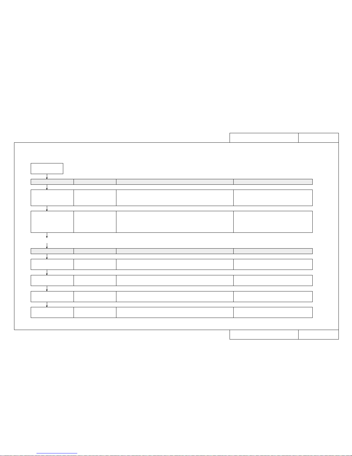
■ Fault maintenance work procedures and how to use the Maintenance Manual
When a user reports an equipment fault, use the following procedure to carry out fault recovery tasks.
A fault occurs
Task Page Details Reference materials
Check fault circumstances,
select fault details from
Trouble-Shooting Lists
Trouble-Shooting List
TRB❉❉❉❉
Check circumstances by “fax” or “telephone”. Check error
messages, check user usage conditions, retry after changing settings, output
diagnostic pattern, etc. Select fault symptoms produced by user from
the Trouble-Shooting List.
Conduct a consultation by “fax” or “telephone”.
Check possibility of user error or recovery by daily inspection. Check error
messages, check user usage conditions, output diagnostic pattern, output
setup list. Retry after changing settings, etc.
Primary Consultation
ENT❉❉❉❉
Operation Manual, basic
knowledge, daily care, periodic maintenance/
inspection/cleaning
Task Page Details Reference materials
Gather the necessary
maintenance parts
Matrix Map
MAP❉❉❉❉
Gather the necessary maintenance parts Maintenance Parts list, Maintenance Tools list,
Exploded views
Conduct a tracing inquiry Fault Tracing Procedures
EXA❉❉❉❉
Conduct an inquiry to trace the cause of the fault Basic knowledge
Replace parts and adjust Replacement and Adjustment
Procedures REP❉❉❉❉
Replace or readjust parts suspected to be faulty.
Carry out adjustments after replacing parts.
Basic knowledge
Final check Test Procedures
TST❉❉❉❉
Separate causes of faults and check operation after faults have been
rectified.
Conduct a primary
consultation with the user
• If you are unable to resolve the fault at this point, take the necessary maintenance parts and make an on-site visit.
Page 11
11
CON4020Model Name: RJ–4100
CON4020Model Name: RJ–4100
How to use the Trouble-Shooting Lists (TRB)
How to use the Trouble-Shooting Lists (TRB)
1. How to look up trouble-shooting tables
■ When a user has reported a fault, first select the applicable details from the trouble-shooting lists (TRB) and jump to the specified primary consultation (ENT).
• Faults are broadly classified as those which cause a message to appear in the printer LCD and those which do not.
• For troubles that cause a message to be displayed, select the message as it is.
• Troubles with no message display are classified into the 10 blocks shown below. First select the block then select the appropriate fault details from that block.
2. Definitions of groupings in the case of faults that produce no message display
When Message is Displayed TRB1000
• Printer Status Messages, Data Errors, Command Errors
• CPU System Faults, Mechanical System Faults
When Message is Not Displayed
TRB2000 to TRB2001
•
Trouble with Initialization: Troubles that occur when unpacking immediately after delivery are grouped here.
Check this group for a similar trouble occurring other than immediately after delivery.
Troubles concerning the series of operations up to the enabling of printing are grouped here.
•
Trouble with Plotting: This group concerns printing quality problems.
•
Trouble with Media Feed: This group concerns problems with the media path.
•
Trouble with Media Cutting: Cutter section problems are grouped here.
Plotting precision problems are grouped here.
•
Problem Involving Noise: Troubles that produce abnormal noise from the driving section.
• Online/Function Problems: Online plotting function problems.
Troubles involving driver software, consumable items, peripheral devices are grouped here.
• Other: Troubles concerning the series of operations up to the enabling of printing are grouped here.
Page 12
12
CON4030Model Name: RJ–4100
CON4030Model Name: RJ–4100
How to use Primary Consultation (ENT)
How to use Primary Consultation (ENT)
■ When a user has reported a fault, first select the applicable details from the trouble-shooting lists (TRB) and then check the conditions in detail by asking questions in
accordance with the primary consultation (ENT) shown below.
• Ask the questions in order, beginning with 1-1, and move to the next question if there is nothing abnormal. If an abnormality is revealed, carry out the task indicated by
the arrow [→].
• If all questions produce nothing abnormal, then jump to the specified matrix map (MAP).
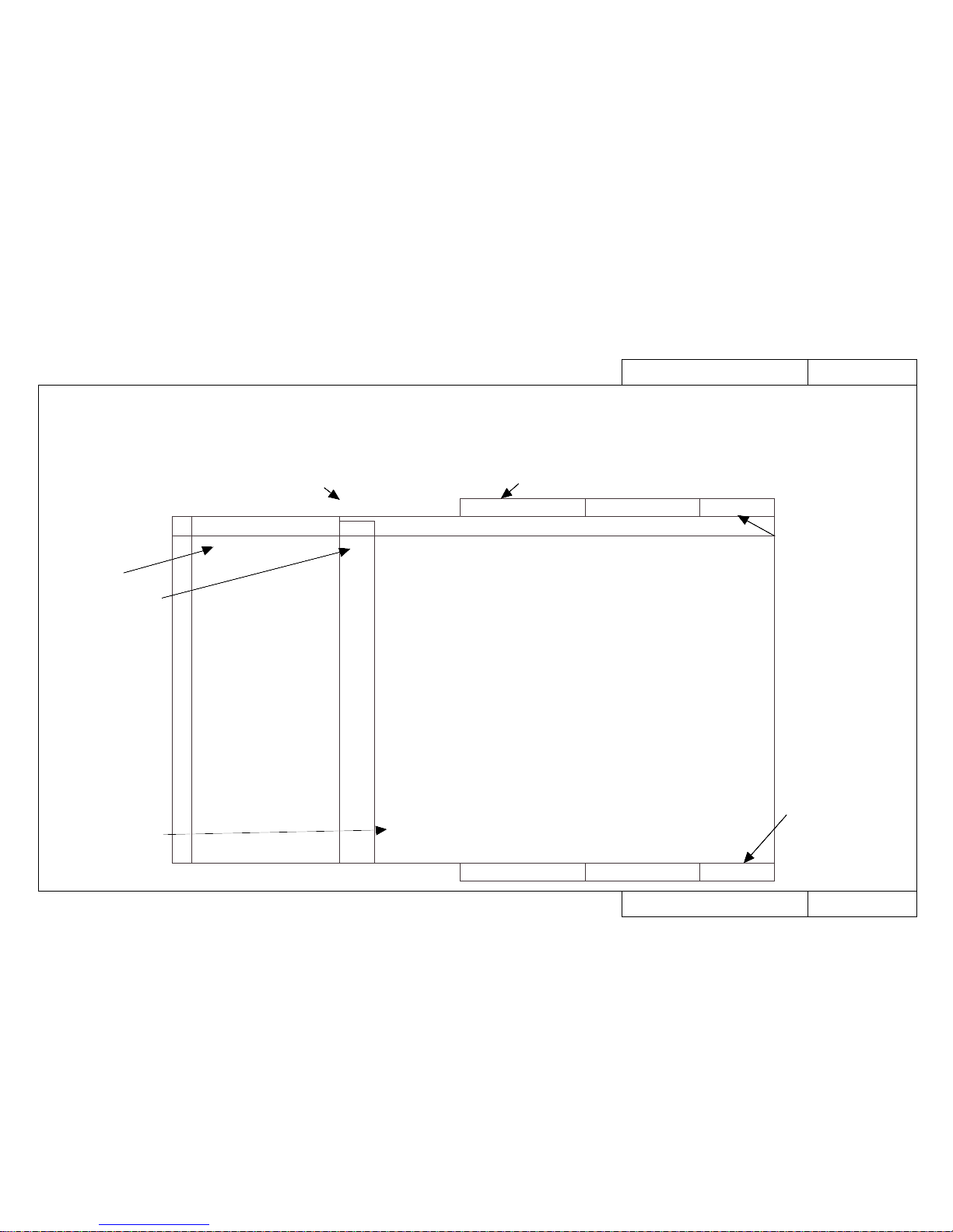
ENT2000Model Name: RJ–4100
ENT2000Model Name: RJ–4100
Trouble with Initialization
When No Error is Displayed on the Printer's Liquid Crystal Display
12• No power
• Faulty liquid crystal display (no display/unstable display)
1-1
1-2
1-3
1-4
1-5
1-5
1-6
1-7
1-8
1-9
• Has the power plug come away from the outlet?
→ Plug the cord all the way into the socket.
• Has the cord come away from the printer inlet?
→ Plug the cord all the way into the printer socket and try again.
• Is power available at the power outlet?
→ Check the power supply.
• Is the AC power supply securely earthed? (grounding)
→ Make sure it is connected to a 100 V or 200 V ground and confirm by testing the display again.
• With the cord inserted into the power outlet, is the prescribed voltage available at the end of the cord?
→ Switch off the printer, leave it for ten minutes then try switching on again.
• The overcurrent detector circuit in the printer's power supply may have tripped.
→ Leave it for 10 minutes then try switching on again.
• Are there any large power-consuming peripheral devices, such as a copier, on the same outlet?
→ Take power from a separate power source.
• Is there any equipment near the printer that is producing strong noise?
→ Separate the power supplies of nearby equipment and try increasing their distance from the printer.
• Is the power cable broken?
→ It's no good connecting a broken cable. Replace the power cable.
• Is the LCD unit damaged?
→ It needs to be repaired by the Serviceman.
Please request repair.
❈ If the above procedures do not improve the symptoms, the main unit has probably developed a fault for
some reason.
Go to MAP2000
No. Symptom
Sequence
Items to be Confirmed
When No Error is Displayed on the Printer's Liquid Crystal Display
Trouble with Initialization
Whether an error message is displayed
Fault details
Questioning sequence
If all questions
produce no
abnormality,
jump to the
specified matric
map (MAP)
Major classification of fault details
Page specified by
trouble-shooting
list (TRB)
Page specified by
trouble-shooting
list (TRB)
Page 13
13
CON4040Model Name: RJ–4100
CON4040Model Name: RJ–4100
How to use the Matrix Map (MAP)
How to use the Matrix Map (MAP)
■ When the primary consultation (ENT) has not revealed any anomaly, gather the necessary maintenance parts according to the matrix map (MAP) shown below and visit
the user.
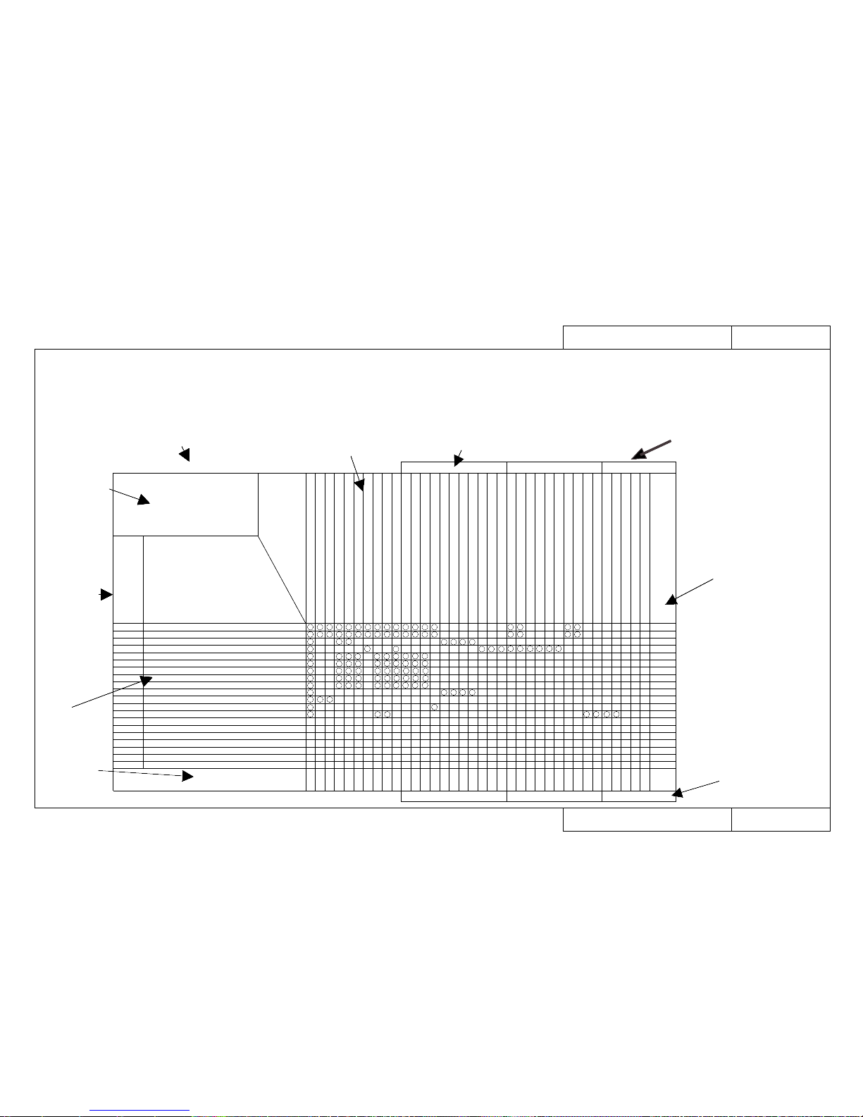
Major classification of fault details
ENT number
selected from
trouble-shooting
list (TRB)
Whether an error message is displayed
Major classification
of fault details and
range of ENT numbers
Fault
details
Replacement
and adjustment
procedure page
Names and drawing numbers of
required parts
Page specified
by primary
consultation (ENT)
Page specified
by primary
consultation (ENT)
Fault-tracing
procedure
(EXA) page
When Message is Not Displayed Trouble with Initialization Model Name: RJ-4100 MAP2000
Trouble with Initialization Model Name: RJ-4100 MAP2000
When Message is Not Displayed
Trouble with Initialization
ENT2000 to ENT2070
TroubleShooting
List
ENT. No.
Problem
- Power supply does not come on
- LCD faulty (no display/erratic display)
- Initial filling of inks failed
- Initial filling is completed but no ink comes out
- After power is switched on, nothing works
- When power is applied, “Initializing” appears and then a reset is executed.
- After mounting media, initial operation fails
- Printer does not work even with the cover closed
- Printer does not stop even with the cover opened
- Ink cartridges are installed but not recognized
- Can not make entries from the operating panel
- Data is received but not plotted
- Media is not suction
Replacement and Adjustment Procedure REP. No.
Name and Diagram Number of
Replacement Part
DF-41524 Main Board Assembly
DF-40097 Panel Board Assembly
DF-40114 Panel Cable
DF-40100 Cover Switch Assembly
DF-40099 Lever Sensor Assembly
DF-40108 Paper Sensor Y Assembly
DF-41525 Head Board Assembly
DF-40102 Paper Sensor F Assembly
DF-40103 Paper Sensor R Assembly
DF-40118 Y Cable (A0) x 1
DF-40115 Switch Cable Assembly
DF-40095 Power Board Assembly
DF-41535 DC Cable Assembly
RJ8-ETH13 Network Interface Board (Supply item)
DF-40106 Detector Assembly (Black)
DF-40107 Detector Assembly (Y)
DF-40146 Detector Assembly (M)
DF-40147 Detector Assembly (C)
DF-40123 Cap Assembly
DF-40124 Pump Assembly
DF-40126 Maintenance Station Assembly
DF-40119 Head Cable (Black)
DF-40120 Head Cable (Color)
DF-40121 Print Head Assembly (Black)
DF-40122 Print Head Assembly (Color)
DF-40488 O-rings (Large)
DF-40487 O-rings (Small)
DF-40101 Waste Fluid Box Detector Switch Assembly
SIM8M, SIM16M, SIM32M Extended Memory (32 MB)(Supply item)
DF-40173 Vacuum Fan Assembly
DF-40174 Fan Cable A Assembly
DF-40132 Fan Cable B Assembly
DF-40133 Fan Cable C Assembly
1140
1160
1170
1110
1100
1410
1420
1190
1200
1360
1130
1150
1130
1480
1350
1350
1350
1350
1240
1260
1270
1400
1400
1390
1390
1530
1530
1120
1490
1080
1080
1080
1080
Fault-Tracing Procedure EXA No.
2000
2000
2010
2020
2030
2030
2030
2030
2030
2040
2050
2060
2070
2000
2000
2010
2020
2030
2030
2030
2030
2030
2040
2050
2060
2070
Page 14
14
CON4050Model Name: RJ–4100
CON4050Model Name: RJ–4100
How to use the Fault-Tracing Procedure (EXA)
How to use the Fault-Tracing Procedure (EXA)
■ Gather the parts specified by the matrix map (MAP), visit the user and carry out the task of recovery in accordance with the fault-tracing procedure (EXA) shown below.
• First, check again on-site that there was no mistake about the primary consultation. (EXA and ENT page numbers are the same)
• Carry out the checking tasks in order, beginning with 1-1, and move to the next task if there is nothing abnormal. If an abnormality is revealed, carry out the task indi-
cated by the arrow [→].
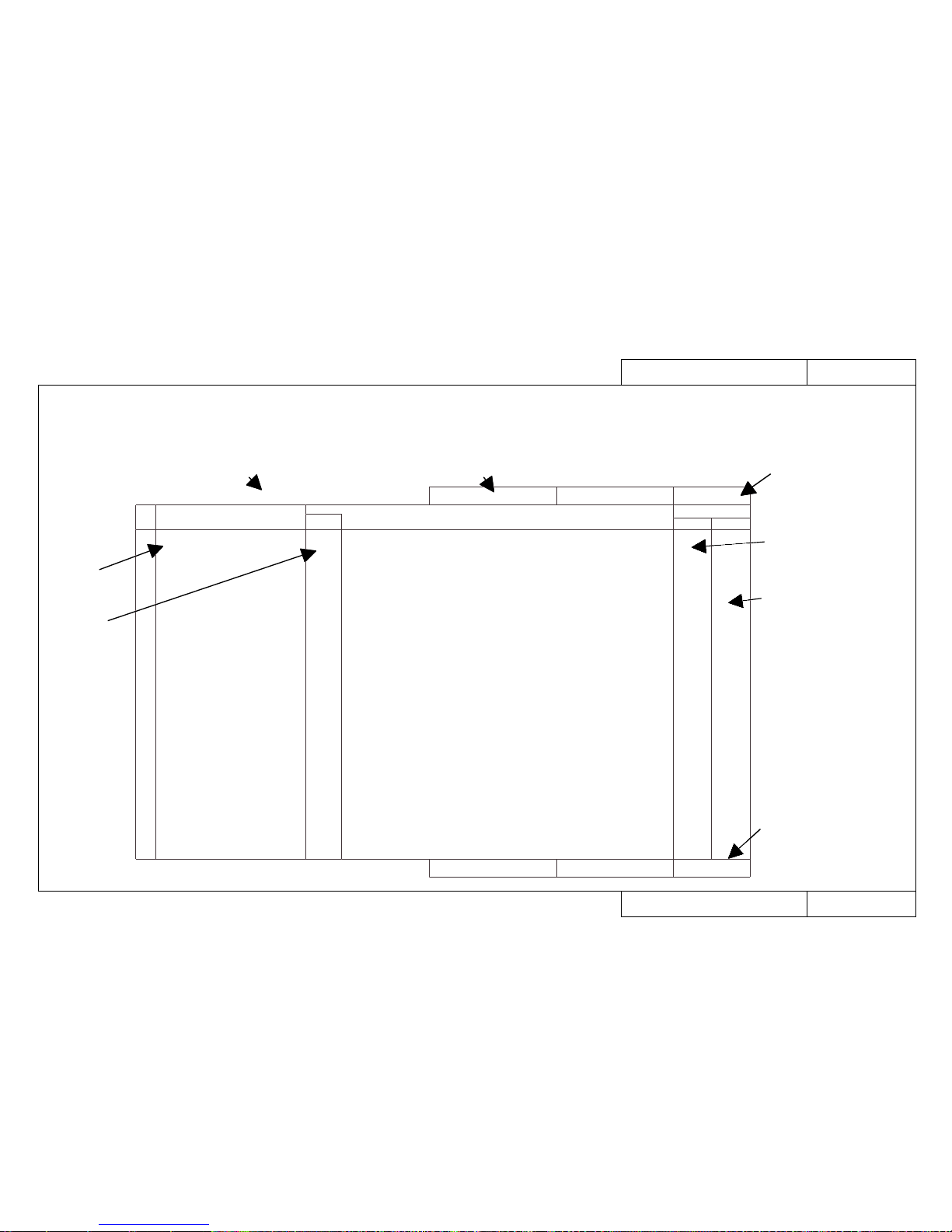
EXA2000Model Name: RJ–4100
EXA2000Model Name: RJ–4100
Trouble with Initialization
When No Error is Displayed on the Printer's Liquid Crystal Display
12• No power
• Faulty liquid crystal display (no display/unstable display)
1-1
1-2
1-3
1-4
1-5
1-6
1-7
1-8
• Is there a broken or shorted lead in the switch cable assembly (between the switch and
power supply board)?
Use a tester to check for broken or shorted leads.
→ Replace the switch cable assembly.
• Do the "Power supply voltage check 100 V AC"
• Do the "Power supply voltage check 5 V DC"
• Do the "Power supply voltage check 24, 42 V DC"
• Check the panel cable connectors on the panel board and main board.
Are they inserted obliquely? Are they securely locked?
Check Main board J113 (PANEL), panel board J301 (MAIN)
→ Reconnect the connectors.
• The panel cable may be faulty.
→ Replace it.
• Is there a fault in the panel board assembly liquid crystal display?
→ Replace the panel board assembly.
• The main board assembly may be damaged.
→ Replace it.
No. Symptom
Sequence
Items to be Confirmed
When No Error is Displayed on the Printer's Liquid Crystal Display
Trouble with Initialization
1130
1630
1640
1650
1170
1160
1140
REP BAC
GO TO Ref. Pages
Whether an error message is displayed
Fault details
Fault-tracing
sequence
Major classification of fault details
Page specified by
matrix map (MAP)
Page specified by
matrix map (MAP)
Replacement and
adjustment procedure
(REP) page reference
Hidden diagnostic
procedure page
reference
Page 15
15
CON4060Model Name: RJ–4100
CON4060Model Name: RJ–4100
How to use Replacement and Adjustment Procedure (REP)
How to use Replacement and Adjustment Procedure (REP)
■ If the fault-tracing procedure (EXA) has produced a replacement task, carry out the work of replacement and adjustment in accordance with the replacement and adjustment procedure (REP) shown below.
• If you don’t know how to go about the removal of covers involved in replacing a part, refer to REP1010 to REP1060.
• If there is a page listed in the top right “GO TO TEST No.” column, you must jump to the test page and carry out a final check.
Y Motor Assembly
Screws
Screw
REP1280Model Name: RJ–4100
REP1280Model Name: RJ–4100
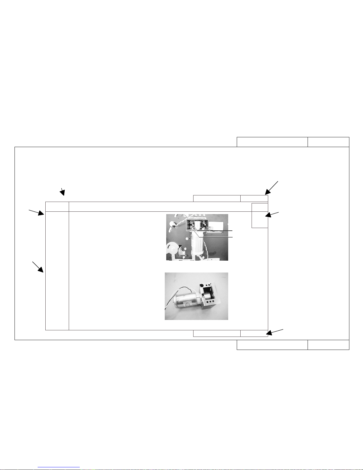
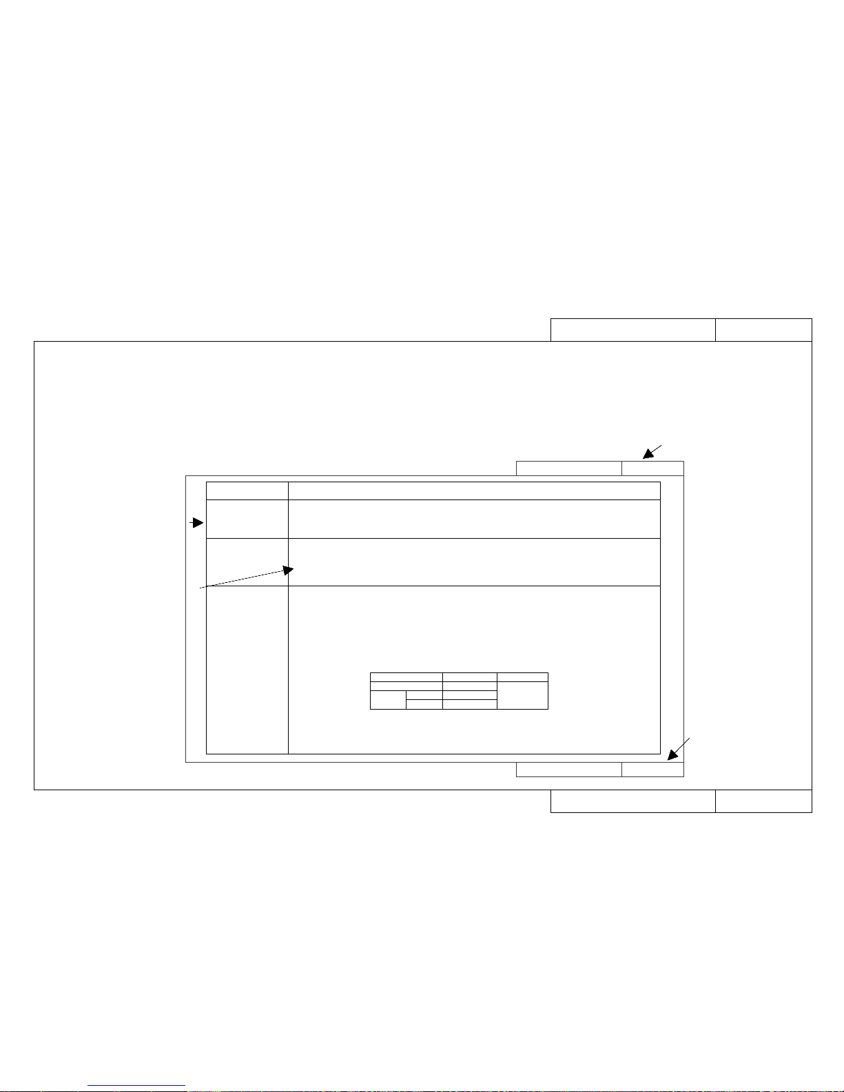
How to replace the Y Motor Assembly
How to replace the Y Motor Assembly
GO TO
TEST NO
1001
TEST4
Item Replacement and Adjustment Procedure
1. Replacement
Procedure
2. Adjustment
and
Examination
Procedure
Replace the Y Motor Assembly
1. Remove the Left and Right Covers. (Refer to REP1010)
2. Remove the Rear Paper Guide. (Refer to REP1040)
3. Remove the Steel Belt. (Refer to REP1290)
4. Open the Control Box. (Refer to REP1050)
5. Disconnect connector J119 (YMOT) from the Main Board
Assembly.
6. Remove the Y Motor Assembly (3 fastening screws).
7. Assembling is the reverse of the removal procedure.
Reference: Since the Y Motor Assembly Cable passes below
the Cartridge Unit, the work will be easier if you
remove the two Cartridge Base screws and push
it back.
1. Carry out the Steel Belt Tensioning Adjustment. (Refer to
REP1550)
Replacement and adjustment item
Replacement
procedure
Adjustment
procedure
and items to
be checked
Page specified by
the fault-tracing
procedure (EXA)
Page specified by
the fault-tracing
procedure (EXA)
Test procedure (TST) page.
You must go to this page
Page 16
16
CON4070Model Name: RJ–4100
CON4070Model Name: RJ–4100
How to use Test Procedure (TST)
How to use Test Procedure (TST)
■ After completing replacement and adjustment in accordance with the replacement and adjustment procedure (REP), if “GO TO TEST No.” is specified, carry out a final
check in accordance with the following test procedure.
• If you do not understand how to go about the testing operation, refer to the reference pages in the text.
TST1000Model Name: RJ–4100
TST1000Model Name: RJ–4100
Test Procedures (Test 1 to Test 3)
Test Procedures (Test 1 to Test 3)
Item Test Procedure
Test 1:
Printing from User's Host
Computer
Test 2 :
Print a Test Print
Test 3:
Skew Check
1. With the cooperation of the user/operator, have the user's data printed in the user's operating environment.
2. Check that the printing is normal.
1. Load A3 size media in the printer.
2. Print a “Test Print”. Press the [Resolution] key while you hold down the [Shift] key.
3. Check that the printing is normal. (Refer to PAT1000 for checking printing quality)
1. Load roll media in the printer (thick coated paper).
2. Select “Adjustments/Skew Verification” from the self-diagnostics menu. (Refer to BAC2030)
3. When “Please input paper feed length [m] (default 1.0 m)” is displayed, set the paper feed length
using the “Setting Value +” key to increase the setting or “Setting Value -” key to decrease the setting.
4. End if “Measurement result ± ✼.✼✼✼, ± ✼.✼✼✼” (skew values on left and right sides of the media) are both within
the standard values shown below.
5. Switch off the power when the test is completed.
Standard values
Within ±1.5 mm
Within ±2.5 mm
Within ±10 mm
Roll Media
Cut Media
Conditions
7m
50m
Standard values
Specified Media
Thick
coated
paper
Test number
and name of
test
Test procedure
and items to be
checked
Page specified by replacement
and adjustment procedure (REP)
Page specified by
replacement and
adjustment procedure
(REP)
Page 17
17
CON5000Model Name: RJ–4100
CON5000Model Name: RJ–4100
Daily Care
Daily Care
Daily Care
This section explains the details of daily maintenance (including cleaning, ink cartridge replacement, cutter replacement, etc.)
How to Clean the Printer Main Unit CON5010
How to Clean the Printer Main Unit CON5011
How to Replace Ink Cartridges CON5020
How to Replace the Cutter CON5030
How to Replace the Waste Fluid Box CON5040
Page 18

18
CON5010Model Name: RJ–4100
CON5010Model Name: RJ–4100
How to Clean the Printer Main Unit
How to Clean the Printer Main Unit
RJ-4100 printer should be wiped free of dirt with a dry
soft cloth.
Plotting Board
Cutting Groove
Use a soft damp cloth to wipe away
any paper fluff adhering to the printing board and cutting groove.
♦ The power switch of the RJ-4000 series printer should be switched off
during cleaning.
♦ Don’t use solvents such as thinners or benzene that will damage the finish.
♦ Covers that are fixed with screws contain electrical components and
must not be opened during cleaning.
♦ Paper dust which is produced when the printer is working should be
removed periodically. Make sure that it does not get blown around.
♦ Stubborn dirt that is difficult to remove may be removed with a lint-free
cloth dampened with alcohol.
CAUTION:
♦ Paper dust and fluff will accumulate with long term use and stick to
the plotting board and cutter groove and may cause printing quality and
cutting performance to deteriorate.
They must be cleaned periodically.
IMPORTANT:
Brush
Grid Roller
Use a soft damp cloth to wipe away
any paper dust sticking to the pressure roller.
Clean the grid roller with a nylon
brush.
♦ Paper fluff sticking to the pressure roller and movable roller may prevent
normal feeding of the media and produce a “Skew Check Error”.
They must be cleaned periodically.
IMPORTANT:
Page 19
19
CON5011Model Name: RJ–4100
CON5011Model Name: RJ–4100
How to Clean the Printer Main Unit
How to Clean the Printer Main Unit
Use a cotton bud to wipe away any dust and paper fluff from the front and back
paper sensor covers in two places.
Paper Sensor Cover
♦ Progressive soiling will affect the sensitivity of the sensors and faulty
detection of the media in the initial operation may cause a “Skew Check
Error”. They must be cleaned periodically.
IMPORTANT:
Page 20
20
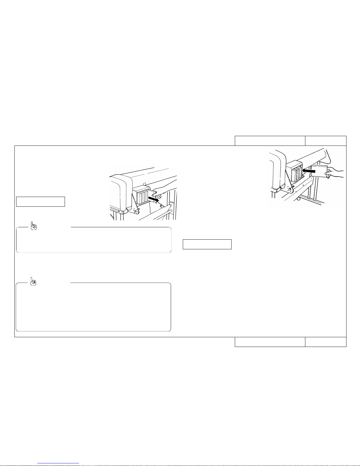
When a RJ-4100 Series printer is displaying “No ink” or “No cartridge”, the cartridge
should be replaced or filled without delay. Also, ink cartridges should be prepared
when “[YMCK] Ink Near End” is displayed.
Step 1
If “No ink” appears in the message display section, when there is no printing operation in
progress, from the back of the printer, pull out
the ink cartridge whose color is indicated.
Step 2
Open the new ink cartridge packet.
[YMCK] cartridge
♦ Each letter Y, M, C, K in the display indicates a color: “Y” (yellow),
“M” (magenta), “C” (cyan), “K” (black).
♦ Colors for “no ink” are expressed as colors 1 to 4.
Reference:
CON5020Model Name: RJ–4100
CON5020Model Name: RJ–4100
How to Replace Ink Cartridges
How to Replace Ink Cartridges
Step 3
Insert the new cartridge in the slot at the
back of the printer.
Step 4
Check that the display has reverted to its
permanent display.
Reference:
♦ Only specific cartridges can be used. They also have a particular place and
orientation. Be careful not to confuse the location and orientation.
♦ Don’t open the sealed package until you are ready to insert the cartridge in the slot.
If a cartridge is stored for a long period with the seal opened, the printing may be
patchy.
♦ Cartridges should be used within two years of the date printed on the package.
An ink cartridge that has been mounted in the printer for two years should be
replaced.
♦ A cartridge that has been mounted in the printer should be replaced within six months.
Plot OK
Page 21
21
CON5030Model Name: RJ–4100
CON5030Model Name: RJ–4100
How to Replace the Cutter
How to Replace the Cutter
Depending on the type of roll media, paper dust may build up in the cutter groove
and on the cutter blade causing poor cutting. In such cases, the cutter should be
cleaned or replaced or the cutter groove should be cleaned.
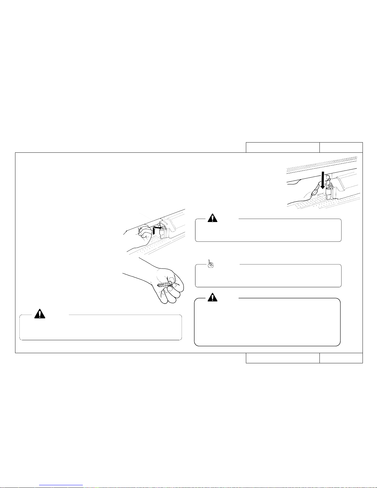
The cutter is a consumable item. It it cuts badly, replace it.
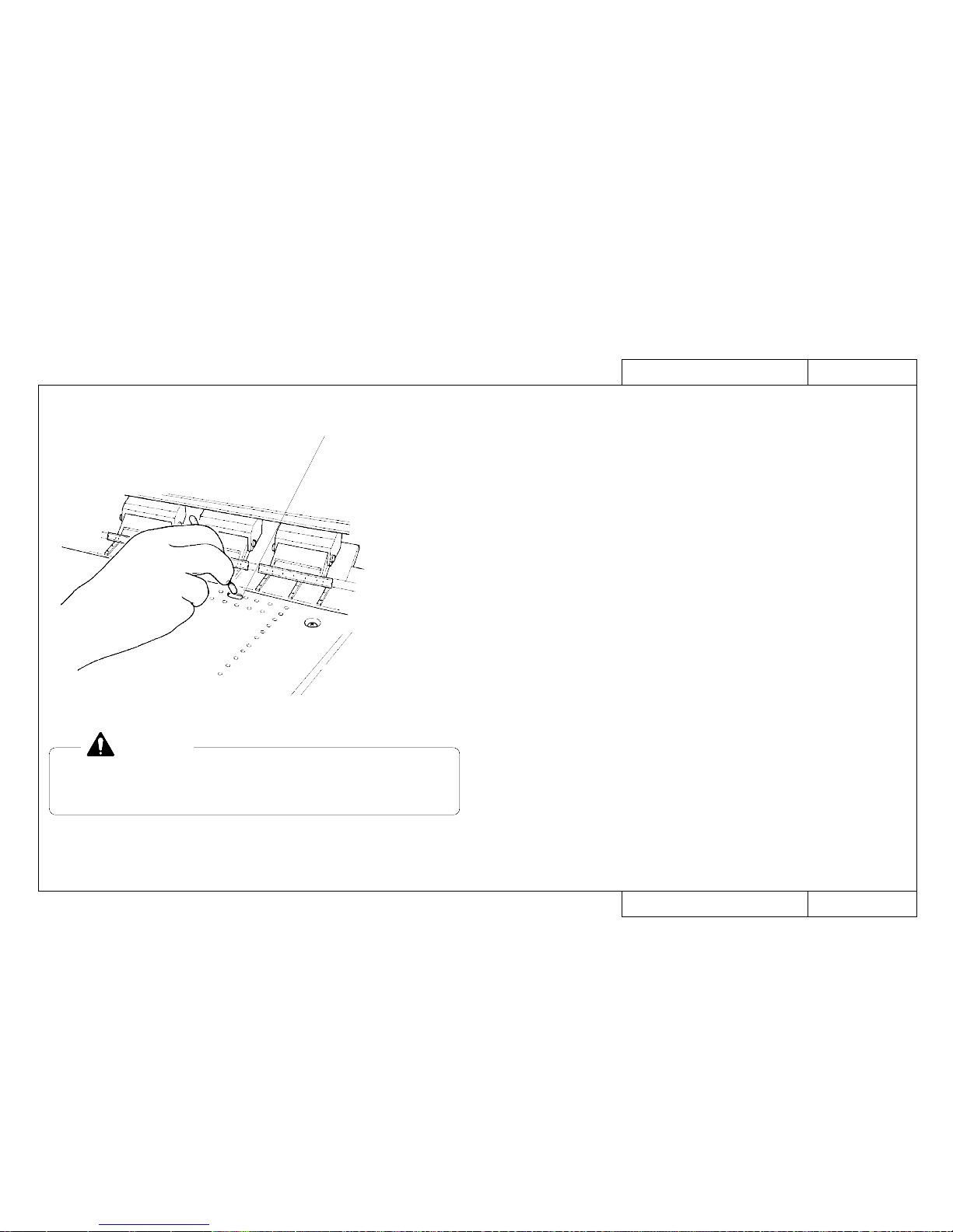
Step 1
Switch off the power and bring the head to the center.
Step 2
Press the cutter down with your finger and rotate
the arm to the front. Take out the cutter.
Wipe the cutter blade with a dry cloth or replace
the cutter.
Step 3
Insert a new cutter in the hole in the head. As
you push down on the cutter, restore the cutter arm over the cutter. The cutter will only go
in one way.
Cutter Arm
♦ There is a spring in the cutter mounting hole. Be careful not to lose it
when you replace the cutter.
CAUTION:
♦ The cutter blade is very hard and brittle. Be careful not to knock it or
drop it.
Step 4:
Return the head to the right end and switch on the power.
CAUTION:
♦ Since the life of the cutter depends on the type and thickness of the media
and the usage environment, it is recommended that a spare cutter be
procured.
Reference:
The auto-cut function cannot be used with some types of recommended
media.
If these types of media are used, a commercial cutter (such as OLFA 30B)
or scissors must be used for cutting.
The types of recommended media than cannot be cut by auto-cut are:
- Indoor cloth - Yupo tac film
- Fire-resistant cloth - Yupo film
- Outdoor cloth
CAUTION:
Page 22
22
CON5040Model Name: RJ–4100
CON5040Model Name: RJ–4100
How to Replace the Waste Fluid Box
How to Replace the Waste Fluid Box
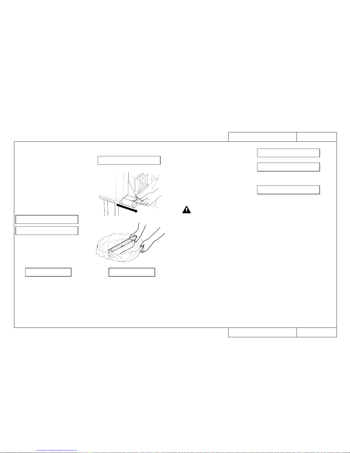
Waste ink is held in the waste fluid box at the back of the printer. Replace the waste
fluid box when it becomes full.
Step 1
When the printer is stopped and the message, “Chk Waste Ink Tank” appears,
order a waste fluid box to be supplied.
Step 2
When the message, “Waste Fluid Tank
Full” appears, pull out the waste fluid box.
When the waste fluid tank is removed, the
message, “No Waste-Ink Tank” will
appear.
Step 3
Without tipping it up, transfer the waste
fluid box to a plastic bag for disposal.
Chk Waste Ink Tank
No Waste-Ink Tank
Waste-Ink Tank Full
After has appeared, the Waste-Ink Tank Full display
will appear after printing about 20 pages of A1 media (with 20% printing) or cleaning
about 40 times.
Chk Waste Ink Tank
Step 4
Insert a new waste fluid box in the printer.
Step 5
Use the [VALUE +] or [VALUE -] keys on
the purple part of the operating panel to
change the display to “Yes”.
Step 6
Press the [Enter] key on the purple part of
the operating panel.
♦ The waste fluid box can be treated as non-combustible garbage.
♦ Don’t squeeze the absorbent sheet soaked with waste fluid or
the waste fluid may leak.
♦ Since it would be dangerous for children to lick or swallow the absorbent
sheet soaked with waste fluid, it should be disposed of promptly or kept
out of the reach. If the waste fluid is accidentally touched, wash immediately
with soap and water. If waste fluid gets into the eyes, wash with plenty of
water and consult a physician. If it is licked, immediately gargle and wash
with water. If any has been swallowed, as a matter of urgency, drink copious
quantities of water and be sure to consult a physician.
♦ If the waste fluid box has been pulled out by mistake, press the enter key
when “Change Tank?: No” is displayed.
Change Tank? No
Change Tank? Yes
Plot OK
CAUTION:
Page 23

23
CON6000Model Name: RJ–4100
CON6000Model Name: RJ–4100
How to Move the Printer Main Unit
How to Move the Printer Main Unit
This section explains the procedure for moving a printer which is in use to another
floor in the same building or to another building.
How to move on the same floor or by elevator to another floor
A serviceman need not be present but the following procedure should be explained
to the user.
CAUTION:
• Two people are required to move the printer.
• Cleaning is not necessary.
• Cartridges, cutter, waste fluid box may remain installed.
• Be careful to keep the printer level. If it is tilted, waste may spill from the fluid
box.
1. With power off, bring the head to the home position and attach head fastening fittings with wing screws.
2. Remove the power cable and interface cable.
3. Undo castor locks and move the printer by pushing it horizontally.
4. When the move is finished, lock the castors, turn the wing screws and remove
the head fastening fittings.
How to move to a different building by vehicle
A serviceman must bring the following items and follow the procedure set out
below.
• Main unit packing box
• Vinyl bag
• Head fastening plate (DF-40549) and wing bolt (DE-48262)
• Cable keeper (DF-40338) and lever keeper (DF-40337)
• Waste fluid box (Number RJ8-HEB)
• Head cleaning jig
• Packing tape, gum tape, bubble wrap
• PP strapping and stopper (for long distance transportation)
CAUTION:
• For safety, always have two people to dismantle and assemble the printer.
• Always have two people to transport the printer and load and unload it on the
vehicle.
• If the user wishes you to take away the waste fluid box that has been removed
and the packing used for transportation, remove them.
• After the move, carry out the initial filling and wait at least 30 minutes before printing otherwise printing quality can not be assured.
1. Remove the four cartridges.
2. Carry out head cleaning. (Refer to REP1620)
3. With power off, bring the head to the home position and attach the head fastening
plate with the wing bolt.
4. Remove the power cable and interface cable.
5. Remove the waste fluid box and install a new one.
6. Install the cable keeper and lever keeper and fasten them with packaging tape.
7. Attach packaging tape so the front cover will not open and the waste fluid box will
not come out.
8. Remove the main unit from the legs, place it in the packing box and apply gum
tape and PP strapping.
9. Don’t dismantle the legs. Wrap them in bubble wrap.
(Remove the tray assembly and wrap it separately)
(If it needs to be dismantled to fit in the vehicle, dismantle and wrap each piece
separately.)
10. Transport by vehicle and on arrival at the destination, refer to the basic “Printer
Preparation” in the operation manual and make sure it is printing correctly.
How to Move the Printer Main Unit
Page 24
24
TRB0000Model Name: RJ–4100
TRB0000Model Name: RJ–4100
Trouble-Shooting Lists
Trouble-Shooting Lists
Trouble-Shooting Lists
When Message is Displayed
How to Use LEDs to Check CPU System TRB1001
and Mechanical System Faults
Printer Status Messages TRB1000
Data Errors TRB1000
Command Errors TRB1000
CPU System Faults TRB1000
Mechanical System Faults TRB1000
When Message is Not Displayed
Trouble with Initialization TRB2000
Trouble with Printing TRB2000
Trouble with Media Feed TRB2000
Trouble with Media Cutting TRB2001
Problem Involving Noise TRB2001
Online/Function Problems TRB2001
Other TRB2001
Page 25
25
When Message is Displayed
When Message is Displayed
TRB1000Model Name: RJ–4100
TRB1000Model Name: RJ–4100
Trouble-Shooting 1/3 (List of Faults)
Trouble-Shooting 1/3 (List of Faults)
Cases where an error message is displayed on the liquid crystal display of the main printer unit
GO TO ENT No.Minor Faults CPU System/Mechanical System Faults GO TO ENT No.
Printer Status Messages
CPU System Faults
• Cover Open
• Lever Up
• Cover and Lever
• Undefined Media
• Media Skew Error
• [User 1] Media End
• Remove Media
• Roll Media End
• Media Cut Error
• Not enough memory SIMM 12 MB
• [KCMY] Ink Low
• [KCMY] No Ink
• [KCMY] No Cartridge
• Capping position not specified
• Not Filled
• No Waste Fluid Box
• Check Waste Fluid Box
• Waste Fluid Box Full
• Ink Type Change
• Wrong Ink Type
ENT1000
ENT1000
ENT1000
ENT1010
ENT1020
ENT1030
ENT1040
ENT1050
ENT1060
ENT1070
ENT1080
ENT1090
ENT1090
ENT1100
ENT1110
ENT1120
ENT1130
ENT1140
ENT1140
ENT1150
ENT1160
• E001 Error DRAM (Standard DRAM error)
• E002 Error Opt.DRAM (Optional DRAM error)
•E016CPUErr[00] (Interrupt exception error)
•E016CPUErr[02] (Command boundary exception error)
•E016CPUErr[03] (Data boundary exception error)
•E016CPUErr[04] (Address error exception)
(Load or command fetch)
•E016CPUErr[05] (Address error exception) (Store)
•E016CPUErr[06] (Bus error exception) (Command fetch)
•E016CPUErr[07] (Bus error exception) (Data load)
•E016CPUErr[08] (System call exception error)
•E016CPUErr[09] (Break point exception error)
•E016CPUErr[10] (Reserved command exception error)
•E016CPUErr[11] (Unable to use coprocessor exception error)
•E016CPUErr[12] (Operation overflow exception error)
•E016CPUErr[13] (Trap exception error)
•E016CPUErr[15] (Floating point exception error)
•E016CPUErr[22] (Watch exception error)
•E016CPUErr[32] (Watchdog timeout exception error)
•E016CPUErr[33] (Abort error)
• Error E237 Transfer memory (Transfer memory error/Transfer memory
access error)
• Error E129 NVRAM
ENT1500
ENT1500
ENT1510
ENT1510
ENT1510
ENT1510
ENT1510
ENT1510
ENT1510
ENT1510
ENT1510
ENT1520
ENT1520
ENT1520
ENT1520
ENT1520
ENT1520
ENT1520
ENT1520
ENT1520
ENT1530
Mechanical System Faults
• E065 Error X Motor
• E069 Error X Encoder
• E071 Error X Timeout
• E073 Error X Overcurrent
• E066 Error Y Motor
• E070 Error Y Encoder
• E072 Error Y Timeout
• E074 Error Y Overcurrent
• E075 Error Sensor Fault
ENT1700
ENT1700
ENT1700
ENT1700
ENT1710
ENT1710
ENT1710
ENT1710
ENT1720
Data Errors
• Network Detection Error
• Network Initialization Error
ENT1230
ENT1230
Command Errors
• MH01 Error (Undefined Command)
• MH02 Error (Parameter Error)
• MH03 Error (Numerical Error)
• MH04 Error (Undefined Character Set)
• MH07 Error (Buffer Overflow)
ENT1250
ENT1250
ENT1250
ENT1250
ENT1250
Page 26
26
TRB1001Model Name: RJ–4100
TRB1001Model Name: RJ–4100
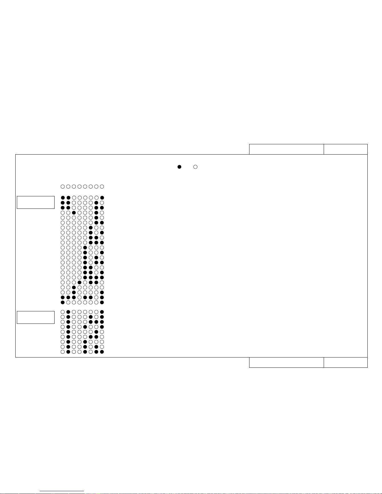
How to Use LEDs to Check CPU System and Mechanical System Faults
How to Use LEDs to Check CPU System and Mechanical System Faults
• When the printer stops working and nothing appears on the liquid crystal display (LCD),
a fault has probably occurred in the CPU system or the mechanical system.
In that case, open the control box and check the error by the LEDs on the main board. is on, is off.
LED display
12345678
• E001 Error DRAM
CPU System Faults
Details of Error
• E002 Error Opt.DRAM
• E002 Error Opt.DRAM
• E016CPUErr[00]
• E016CPUErr[02]
• E016CPUErr[03]
• E016CPUErr[04]
• E016CPUErr[05]
• E016CPUErr[06]
• E016CPUErr[07]
• E016CPUErr[08]
• E016CPUErr[09]
• E016CPUErr[10]
• E016CPUErr[11]
• E016CPUErr[12]
• E016CPUErr[13]
• E016CPUErr[15]
• E016CPUErr[22]
• E016CPUErr[32]
• E016CPUErr[33]
• E237 Error Transfer memory
• E129 Error NVRAM
(Standard DRAM error)
(Optional DRAM 1 error)
(Optional DRAM 2 error)
(Interrupt exception error)
(Command boundary exception error)
(Data boundary exception error)
(Address error exception) (Load or command fetch)
(Address error exception) (Store)
(Bus error exception) (Command fetch)
(Bus error exception) (Data load)
(System call exception error)
(Break point exception error)
(Reserved command exception error)
(Unable to use coprocessor exception error)
(Operation overflow exception error)
(Trap exception error)
(Floating point exception error)
(Watch exception error)
(Watchdog timeout exception error)
(Abort error)
(Transfer memory error/Transfer memory access error)
ENT1500
Primary Consultation page
ENT1500
ENT1500
ENT1510
ENT1510
ENT1510
ENT1510
ENT1510
ENT1510
ENT1510
ENT1510
ENT1510
ENT1520
ENT1520
ENT1520
ENT1520
ENT1520
ENT1520
ENT1520
ENT1520
ENT1520
ENT1530
• E065 Error X Motor
• E066 Error Y Motor
• E069 Error X Encoder
• E070 Error Y Encoder
• E071 Error X Timeout
• E072 Error Y Timeout
• E073 Error X Overcurrent
• E074 Error Y Overcurrent
• E075 Error Sensor Fault
ENT1700
ENT1700
ENT1700
ENT1700
ENT1710
ENT1710
ENT1710
ENT1710
ENT1720
Mechanical System
Faults
Page 27
27
TRB2000Model Name: RJ–4100
TRB2000Model Name: RJ–4100
Trouble-Shooting 2/3 (List of Faults)
Trouble-Shooting 2/3 (List of Faults)
When Message is Not Displayed
When Message is Not Displayed
GO TO
ENT No.
Cases where no error message is displayed
on the liquid crystal display of the main printer unit
GO TO
ENT No.
Cases where no error message is displayed
on the liquid crystal display of the main printer unit
Trouble with Initialization
Trouble with Printing
• No power
• Faulty liquid crystal display (no display/unstable display)
• Initial filling of inks failed
• Initial filling is completed but no ink comes out
• After power is switched on, nothing works
•
When power is applied, “Initializing” appears and then a reset is executed.
• Media is mounted but the initialization operation is not done
• Printer does not work even with the cover closed
• Printer does not stop even with the cover opened
• Ink cartridges are installed but not recognized
• Can not make entries from the operating panel
• Data is received but not printed
• Media is not suction
ENT2000
ENT2000
ENT2010
ENT2020
ENT2030
ENT2030
ENT2030
ENT2030
ENT2030
ENT2040
ENT2050
ENT2060
ENT2070
ENT3000
ENT3000
ENT3000
ENT3000
ENT3000
ENT3010
ENT3010
• Does not print continuously
• There is an extra feed after printing is finished
• Dots are missing from the printing
• Cleaning does not cure blockage
• Does not print at all
• Does not print a specific color
• The entire surface is printed black
• Printing becomes shaded
• The image contains blurs
• Transverse lines appear to be split
• Black and white lines appear in the printed image
• Edges of printing are blurred
• Many satellites (unwanted dots)
• The printing has whiskers
• Printed lines appear blurred (printing is dirty)
• Mixed color lines do not overlap
• Black and color positions are offset
•
Inaccurate line length in the direction of head movement (Main scanning direction)
• Inaccurate straight line in the direction of head movement (straightness)
•
Inaccurate line distance in the direction of media feed (Subsidiary scanning distance)
• Inaccurate straight line in the direction of media feed (joining precision Y)
• Bad right angle precision
ENT4000
ENT4010
ENT4020
ENT4020
ENT4030
ENT4030
ENT4040
ENT4050
ENT4050
ENT4050
ENT4050
ENT4060
ENT4070
ENT4070
ENT4070
ENT4080
ENT4080
ENT4090
ENT4100
ENT4110
ENT4120
ENT4130
Trouble with Media Feed
• The media comes off when it is initialized or during printing
• The media is skewed or meanders when it is initialized or during printing
• The media becomes wrinkled when it is initialized or during printing
• The media jams when it is initialized or during printing
• The media tears when it is initialized or during printing
• The media size is different after media mounting and initialization
• Tracing paper and thin media cannot be detected
Page 28
28
TRB2001Model Name: RJ–4100
TRB2001Model Name: RJ–4100
Trouble-Shooting 3/3 (List of Faults)
Trouble-Shooting 3/3 (List of Faults)
When Message is Not Displayed
When Message is Not Displayed
GO TO
ENT No.
Cases where no error message is displayed
on the liquid crystal display of the main printer unit
GO TO
ENT No.
Cases where no error message is displayed
on the liquid crystal display of the main printer unit
Problem Involving Noise
Online/Function ProblemsOther
• Abnormal noise when media is sucked down
• Abnormal noise when standing by ready to print
• Abnormal noise when head is moving left and right
• Abnormal noise when media is fed
• Abnormal noise when cutting
ENT5000
ENT5010
ENT5020
ENT5030
ENT5040
ENT6000
ENT6010
ENT6020
ENT6020
ENT6030
ENT6040
ENT6050
ENT6050
ENT7000
ENT7000
ENT7020
ENT7020
ENT7020
ENT7020
ENT7030
ENT7040
ENT7050
ENT7060
• The printer hangs up
• Power shutdown during printing
• The ink cartridges will not go in
• Mounting the media is difficult
• Inserting the scroller is difficult
• Ink has overflowed from the waste fluid box
• Ink overflows from flushing box
• Ink is split around the X-rail
• Trouble related to ink (consumable item)
• Trouble related to media (consumable item)
• Trouble related to cutters (consumable item)
• Trouble related to extended memory (optional item)
• Trouble related to the network board (optional item)
• Can not install the printer driver
• Cannot connect normally with Centronics
• Cannot connect normally with Network
• The scale function does not work correctly
• The rotate function does not work correctly
• The mirror function does not work correctly
• Other functions are not working correctly
• Printing position is offset
• Some data are not printed (omitted)
• Text and printing data are garbled (extra lines appear)
• There is an extra feed after printing is finished
ENT8000
ENT8010
ENT8020
ENT8030
ENT8040
ENT8050
ENT8050
ENT8050
ENT8060
ENT8060
ENT8060
ENT8070
ENT8070
ENT8070
Trouble with Media Cutting
• Does not cut normally
• Cutting occurs during printing
• The cutting operation is normal but the media is not cut
• The cutting is bad and the media jams
• The cutting operation is normal but the media does not fall out
• Inaccurate media cutting
• Cutting is delayed for some time after printing has ended
• White paper is cut
Page 29

29
ENT0000Model Name: RJ–4100
ENT0000Model Name: RJ–4100Primary Consultation
Primary Consultation
Primary Consultation
When Message is Displayed
Printer Status Messages ENT1000
Data Errors ENT1200
Command Errors ENT1250
CPU System Faults ENT1500
Mechanical System Faults ENT1700
When Message is Not Displayed
Trouble with Initialization ENT2000
Trouble with Printing ENT4000
Trouble with Media Feed ENT3000
Trouble with Media Cutting ENT6000
Problem Involving Noise ENT5000
Online/Function Problems ENT7000
Other ENT8000
Page 30
ENT1000Model Name: RJ–4100
ENT1000Model Name: RJ–4100
Printer Status Messages
When Message is Displayed
1
2
3
• Cover Open
This message means that the Front
Cover is open
• Lever Up
This message means that the
Pressure Lever is up.
• Cover and Lever
This message means that the Front
Cover and Pressure Lever are up.
1-1
1-2
1-3
1-4
1-5
1-6
• The front cover is open.
→ Please close the front cover securely.
• Is the pressure lever up?
→ Please lower the pressure lever securely.
• Is the Cover Shaft R fastening screw in place?
→ Maintenance by a Serviceman is required.
• Please open and close the front cover several times. Does the beeper sound when the cover is open?
→ If there is no noise when the cover is opened, the main unit has probably developed a fault for some reason.
Maintenance by a Serviceman is required.
• Please raise and lower the pressure lever several times. Does the beeper sound when the lever is raised?
→ If there is no noise when the pressure lever is raised, the main unit has probably developed a fault for some
reason. Maintenance by a Serviceman is required.
• The power supply may be unstable if several devices are connected to one power outlet.
→ Switch off the power temporarily and try again by connecting to a different outlet.
❈ If the above procedures do not improve the symptoms, the main unit has probably developed a fault for
some reason.
Go to MAP1000
No. Symptom
Sequence
Items to be Confirmed
When Message is Displayed
Printer Status Messages
30
Page 31

ENT1010Model Name: RJ–4100
ENT1010Model Name: RJ–4100
Printer Status Messages
When Message is Displayed
1 • Undefined Media
This message means that when
media was mounted, it was not able
to be recognized.
1-1
1-2
1-3
1-4
1-5
1-6
1-7
1-8
1-9
• Is the type of media that is not being recognized the type of media recommended for the printer?
→ Please change to a recommended media and try again.
• Is a breeze from the airconditioner blowing straight on to the media?
→ Please change the direction of the airstream and try again.
• Is there a scrap of paper or something else covering the paper sensor on the printer?
→ Please refer to "Daily Maintenance" in the Operation Manual and carry out the cleaning.
• Is the media that is not being recognized torn?
→ Replace it with new media.
• Has the media that is mounted already been printed?
→ It is possible that printed media may not be recognised correctly. Replace it with new media.
• Is the pressure lever down properly?
→ Lower the pressure lever securely.
• The media is mounted normally if, during the media detection operation, the media moves forward and backward parallel to
the marker line and the position is the same as before media detection. If the position is different, the mounting of the
media must be repeated.
→ Mount the media again so that the positions before and after media detection are the same.
For details, please refer to “Trouble Shooting” under “Daily Maintenance” in the Operation Manual.
• Is there ink or paper dust, etc. around the printing board and cutter groove?
→ Carry out cleaning with reference to “Trouble Shooting” under “Daily Maintenance” in the Operation Manual.
• Is there strong light falling on the area where the media is mounted?
→ Cover the Y Rail Cover and Front Cover with opaque paper and mount the media again. If the error display disappears,
move the printer to a location away from the strong light and try mounting the media once more.
❈ If the above procedures do not improve the symptoms, the main unit has probably developed a fault for some reason.
Go to MAP1000
No. Symptom
Sequence
Items to be Confirmed
When Message is Displayed
Printer Status Messages
31
Page 32

ENT1020Model Name: RJ–4100
ENT1020Model Name: RJ–4100
Printer Status Messages
When Message is Displayed
1 • Media Skew Error
This message appears when the right
(origin side) edge of the media has
been detected beyond the allowable
range of variation from the standard
position.
1-1
1-2
1-3
1-4
1-5
1-6
• Is recommended media being used?
→ Replace with recommended media and try again.
• Is the pressure lever lowered properly?
→ Lower the lever securely.
• Is there any foreign matter interfering with the media feed, such as paper cuttings sticking to the grid roller?
→ Remove them with a brush, etc.
• In the case of roll paper, is the roll shaft seated properly in both the left and right printer shaft support rollers?
→ Install the shaft properly.
• In the case of roll paper, the media is set correctly if it moves backward and forward parallel to the marker line during media
detection, and it is in the same position as it was prior to detection. However, if the position seems to be offset, it must be
remounted.
→ Mount the media again so that it is in the same position before and after media detection.
• Are you explaining what is meant by skew and meander?
Check this condition in detail during the primary consultation.
Explain that skew up to the figures shown below is within the acceptable limit.
Also, have the repeatability checked and explain that poor repeatability is probably caused by badly mounted media.
No. Symptom
Sequence
Items to be Confirmed
When Message is Displayed
Printer Status Messages
32
Cut sheet
Roll media
Within 1.5 mm
Within 2.5 mm
However, it should be explained that in the case of roll media, if the pressure is left down for a long period with the media
mounted, or in an environment with sudden changes of temperature and humidity, the whole roll may not necessarily feed
properly.
• In a case where the symptoms are not reproduced (no problem up to the fifth sheet then frequent skewing after remounting,
etc.) the method of mounting the media may be at fault and this should be checked with the Operation Manual.
→ Check "Loading the media" under "Installation procedures:" in the Operation Manual.
❈ If the above procedures do not improve the symptoms, the main unit has probably developed a fault for some reason.
Go to MAP1000
1-7
Page 33

ENT1030Model Name: RJ–4100
ENT1030Model Name: RJ–4100
Printer Status Messages
When Message is Displayed
1 • [User 1] Media End
This message is displayed when no
media is mounted or printing in cut
media mode has been completed.
1-1
1-2
• Is the lever down with no media mounted, or has printing in cut media mode been completed?
→ Mount new recommended media.
• When cut media is being mounted, is it placed so that it covers the sensor that detects the trailing edge of the
media?
→ When cut media is being mounted, push it right back until the media suction fan starts to turn and then try
again.
❈ If the above procedures do not improve the symptoms, the main unit has probably developed a fault for
some reason.
Go to MAP1000
No. Symptom
Sequence
Items to be Confirmed
When Message is Displayed
Printer Status Messages
33
Page 34

ENT1040Model Name: RJ–4100
ENT1040Model Name: RJ–4100
Printer Status Messages
When Message is Displayed
1 • Remove Media
This message is displayed, if after
raising the lever during printing and
cutting the media, the lever is lowered
without the media having been
removed.
1-1 • Does the error appear after raising the lever during printing and cutting the media and then removing the
media?
→ Switch on the power again.
❈ If the above procedures do not improve the symptoms, the main unit has probably developed a fault for
some reason.
Go to MAP1000
No. Symptom
Sequence
Items to be Confirmed
When Message is Displayed
Printer Status Messages
34
Page 35

ENT1050Model Name: RJ–4100
ENT1050Model Name: RJ–4100
Printer Status Messages
When Message is Displayed
1 • Roll Media End
This message is displayed when roll
media is being used and the trailing
edge of the media is detected. It will
be cancelled by raising the lever.
1-1 • Is the roll media finished?
→ Replace the roll.
• Have cut media been mounted while roll media is selected?
→ Mount roll media.
• Is the roll media floating?
→ Mount the media again.
• Does "Roll Media End" appear when the pressure lever is up?
→ If this is displayed, maintenance by a Serviceman is required.
❈ If the above procedures do not improve the symptoms, the main unit has probably developed a fault for
some reason.
Go to MAP1000
No. Symptom
Sequence
Items to be Confirmed
When Message is Displayed
Printer Status Messages
35
Page 36

ENT1060Model Name: RJ–4100
ENT1060Model Name: RJ–4100
Printer Status Messages
When Message is Displayed
1 • Media Cut Error
This message is displayed when the
media is not cut and does not fall out
despite the cutting operation having
been performed.
1-1
1-2
1-3
1-4
1-5
1-6
1-7
• Is the type of media that is not being cut the type of media recommended for the printer?
→ Since the message is cancelled when the lever is raised, please change to a recommended media and try
again.
• Is there paper dust or other matter in the cutter groove?
→ Please refer to "Daily Maintenance" in the Operation Manual and carry out the cleaning.
• Is the cutter and cutter spring mounted in the head mount?
→ Mount the cutter.
• Is the cutter cap fitted properly over the cutter blade?
→ Please refer to "Daily Maintenance" in the Operation Manual and refit it then try again.
• Does the usage environment conform to the recommended working environment?
→ Please refer to "Specifications" in the Operation Manual.
• Is dew condensed on the printer?
→ Wait until the printer has adjusted to the environment and the dew has disappeared and then try again.
• Had the tip of the cutter blade become blunt?
→ The cutter is a consumable item. Replace it with a new one and try again.
No. Symptom
Sequence
Items to be Confirmed
When Message is Displayed
Printer Status Messages
36
The auto-cut function cannot be used with some types of recommended
media.
If these types of media are used, a commercial cutter (such as OLFA 30B)
or scissors must be used for cutting.
The types of recommended media than cannot be cut by auto-cut are:
- Indoor cloth - Yupo tac film
- Fire-resistant cloth - Yupo film
- Outdoor cloth
CAUTION:
❈ If the above procedures do not improve the symptoms, the main unit has probably
developed a fault for some reason.
Go to MAP1000
Page 37

ENT1070Model Name: RJ–4100
ENT1070Model Name: RJ–4100
Printer Status Messages
When Message is Displayed
1 • Not enough memory SIMM✼✼MB
(Intermediate code buffer overflow)
When this printer has insufficient
memory for the amount of data sent
by the personal computer, this message indicates the required memory
size.
1-1
1-2
2-1
2-2
Check: Which of the following applies to the error?
No extended memory Go to Step 2-1
Extended memory fitted Go to Step 1-2
Check: In the memory capacity that is printed on the list of setting details, is it only the extended memory that is
increased?
Not increased → The printer will not be aware of extended memory if it is inserted in the
wrong slot.
Please check whether the extended memory is in the proper slot.
Increased Go to Step 2-2
Reference: For details on how to mount extended memory, please refer to "Installing Options" in
the Applications Operating Manual.
Treatment: When the printer was developed, printing data transmitted from HOST was sometimes too great to
be accommodated in memory.
Since the display shows the memory required to plot the data on the screen, advise the user to pro-
cure at least this amount of memory.
Reference: For details on how to mount extended memory, please refer to "Installing Options" in
the Applications Operating Manual.
Treatment: The extended memory that has been procured may be faulty.
❈ If the above procedures do not improve the symptoms, the main unit has probably developed a fault for
some reason.
Go to MAP1000
No. Symptom
Sequence
Items to be Confirmed
When Message is Displayed
Printer Status Messages
37
Page 38

ENT1090Model Name: RJ–4100
ENT1090Model Name: RJ–4100
Printer Status Messages
When Message is Displayed
12• [KCMY] Ink Low
This message is displayed when the
amount of ink shown on the operating
panel is low.
Printing can continue.
(Refer to GID2010 for details)
• [KCMY] No Ink
This message is displayed when the
ink shown on the operating panel has
been used up.
If this message appears while an
image is being printed, stop printing
immediately.
(Refer to GID2010 for details)
1-1
2-1
2-2
• This indicates that the amount of ink shown on the operating panel is low.
→ Advise the operator to complete the current printing output after “Ink Low” has appeared and then replace
the ink cartridge.
❈ If the above procedures do not improve the symptoms, the main unit has probably developed a fault for
some reason.
Go to MAP1000
• This indicates that the ink shown on the operating panel has been used up.
→ For example, if "[KY] No Ink" is displayed, insert new K (Black) and Y (Yellow) ink cartridges.
• Is "[KY] No Ink" displayed on the operating panel despite new ink cartridges having been inserted?
→ If this is displayed, maintenance by a Serviceman is required.
❈ If the above procedures do not improve the symptoms, the main unit has probably developed a fault for
some reason.
Go to MAP1000
No. Symptom
Sequence
Items to be Confirmed
When Message is Displayed
Printer Status Messages
38
Page 39

ENT1100Model Name: RJ–4100
ENT1100Model Name: RJ–4100
Printer Status Messages
When Message is Displayed
1 • [KCMY] No Cartridge
This message indicates that the ink
cartridge that is shown on the operating panel is missing.
1-1
1-2
1-3
1-4
• Is the ink cartridge that is shown on the operating panel inserted?
→ Insert an ink cartridge of the color shown on the operating panel.
• Are the recommended ink cartridges being used?
→ The K, C, M and Y positions in the printer for recommended ink cartridges are pre-determined and the types
should be aligned and inserted accordingly.
• Is the ink cartridge of the color shown on the operating panel properly inserted right to the back of the slot?
→ Insert the ink cartridge right to the back of the slot.
• Is there some foreign matter inside the slot where the ink cartridge of the color shown on the operating panel is
inserted?
→ Remove the ink cartridge of the color shown on the operating panel, check the slot and re-insert the car-
tridge.
❈ If the above procedures do not improve the symptoms, the main unit has probably developed a fault for
some reason.
Go to MAP1000
No. Symptom
Sequence
Items to be Confirmed
When Message is Displayed
Printer Status Messages
39
Page 40

ENT1110Model Name: RJ–4100
ENT1110Model Name: RJ–4100
Printer Status Messages
When Message is Displayed
1 • Capping position not specified
This appears when the capping position is initialized.
1-1 • The printer has developed a fault for some reason.
→ Maintenance by a Serviceman is required.
Go to MAP1000
No. Symptom
Sequence
Items to be Confirmed
When Message is Displayed
Printer Status Messages
40
Page 41

ENT1120Model Name: RJ–4100
ENT1120Model Name: RJ–4100
Printer Status Messages
When Message is Displayed
1 • Not Filled
This message means "Initial filling has
not been done"
1-1 • This message will be displayed when power is switched on at the time of delivery and after head cleaning.
→ Install the four ink cartridges.
At this time, if even one cartridge is not installed, "[KCMY] Cartridge" will appear.
Initial filling begins automatically when all four cartridges have been installed.
❈ If the above procedures do not improve the symptoms, the main unit has probably developed a fault for
some reason.
Go to MAP1000
No. Symptom
Sequence
Items to be Confirmed
When Message is Displayed
Printer Status Messages
41
Page 42

ENT1130Model Name: RJ–4100
ENT1130Model Name: RJ–4100
Printer Status Messages
When Message is Displayed
1 • No Waste Fluid Box
This message means that the waste
fluid box is not installed.
1-1
1-2
1-3
• Is the waste fluid box installed?
→ Check that the absorbent material is not full of waste fluid and install the waste fluid box.
• Check that there is no foreign matter in the waste fluid box slot.
→ Remove the foreign matter and re-install the waste fluid box.
• Is the waste fluid box cracked or split?
→ The waste fluid box is no good and must be replaced. Please contact the Customer Service Desk with
regard to the faulty waste fluid box.
❈ If the above procedures do not improve the symptoms, the main unit has probably developed a fault for
some reason.
Go to MAP1000
No. Symptom
Sequence
Items to be Confirmed
When Message is Displayed
Printer Status Messages
42
Page 43

ENT1140Model Name: RJ–4100
ENT1140Model Name: RJ–4100
Printer Status Messages
When Message is Displayed
12• Check Waste Fluid Box
These messages mean that the waste
fluid tank is filled with waste fluid.
• Waste Fluid Box Full
These messages mean that the waste
fluid tank is filled with waste fluid.
1-1 • Is the waste fluid tank filled with waste fluid?
→ Pull out the waste fluid box and replace it with a new one. Be careful not to soil your hands and clothes with
waste fluid.
CAUTION: Even if the absorbent material is not replaced, this warning message will be cancelled
when you answer [Yes] to the question "Has it been replaced?", so please answer [Yes]
whenever the waste fluid box is replaced.
❈ If the above procedures do not improve the symptoms, the main unit has probably developed a fault for
some reason.
Go to MAP1000
No. Symptom
Sequence
Items to be Confirmed
When Message is Displayed
Printer Status Messages
43
Page 44

ENT1150Model Name: RJ–4100
ENT1150Model Name: RJ–4100
Printer Status Messages
When Message is Displayed
1 • Ink type change
This message is displayed when
switching from dye ink to pigment ink
or from pigment ink to dye ink.
1-1 • Indicates that the ink type (dye or pigment) of the genuine Mutoh cartridges that have been in use up to now is
about to be changed.
If [ENTER] is pressed while "Changing ink" is displayed, the ink type will be switched from dye to pigment or
from pigment to dye.
No. Symptom
Sequence
Items to be Confirmed
When Message is Displayed
Printer Status Messages
44
REFERENCE:
• Ink type switching takes about 10 minutes.
CAUTION:
• If ink type is changed several times, the waste fluid box will become
full.
If several ink type changes are to be made, we recommend that
spare waste fluid boxes (sold separately) be obtained beforehand.
• When switching from pigment type to dye type ink, wait with the power
switched off for at least six hours for the composition of the inks to
stabilize before starting to print. To shorten the waiting time before
starting to print, we recommend that cleaning cartridges
(sold separately) be used to clean the head.
• If this message appears even though the same type of genuine Mutoh cartridges are installed, the ink cartridges should be reinstalled.
❈ If the above procedures do not improve the symptoms, the main unit has probably developed a fault for some
reason.
GO TO MAP1000
Page 45

ENT1160Model Name: RJ–4100
ENT1160Model Name: RJ–4100
Printer Status Messages
When Message is Displayed
1 • Wrong ink type
This message is displayed when ink
cartridges other than genuine Mutoh
cartridges are installed or a mixture of
cartridges of different types are
installed.
1-1
1-2
1-3
1-4
• Is a cartridge other than a genuine Mutoh cartridge installed?
→ Arrange for only genuine Mutoh cartridges to be used.
• Is there a mixture of dye type and pigment type ink cartridges?
→ Install genuine Mutoh ink cartridges of one type only.
• Has the silver label that is attached to the side of the ink cartridge come unstuck? Is it damaged? Has it been
applied crookedly?
→ The ink cartridge is no good and must be replaced.
Please contact your Mutoh local dealer with regard to the faulty ink cartridge.
• Reinstall a genuine Mutoh ink cartridge.
❈ If the above procedures do not improve the symptoms, the main unit has probably developed a fault for some
reason.
Go to MAP1000
No. Symptom
Sequence
Items to be Confirmed
When Message is Displayed
Printer Status Messages
45
Page 46

ENT1230Model Name: RJ–4100
ENT1230Model Name: RJ–4100
Data Errors
When Message is Displayed
12• Network Detection Error
The optional network board can not
be detected
• Network Initialization Error
An error has occurred during the
optional network board initialization
operation
1-1
1-2
• Is the network interface board that is being used the Mutoh special optional network board?
→ This error will occur if the Mutoh special optional network board is not installed. Use the specified network
board.
• Is the network board fully inserted, so that it does not rattle?
→ If it rattles, insert the board again so that it clicks into place and the rattling is completely removed. Then
switch on the power again.
❈ If the above procedures do not improve the symptoms, the main unit has probably developed a fault for
some reason.
Go to MAP1200
No. Symptom
Sequence
Items to be Confirmed
When Message is Displayed
Data Errors
46
Page 47

ENT1250Model Name: RJ–4100
ENT1250Model Name: RJ–4100
Command Errors
When Message is Displayed
1
2
3
4
5
• MH01 Error (Undefined Command)
A command that is not defined in any
command mode has been analysed
• MH02 Error (Parameter Error)
Wrong number of parameters following the command
• MH03 Error (Numerical Error)
Wrong number of parameters following the command
• MH04 Error (Undefined Character
Set)
A nonexistent character set is present
• MH07 Error (Buffer Overflow)
The polygon buffer or the downloadable character buffer has overflowed
1-1 • Are the command settings (except Mutoh driver) the same on both the printer and the host computer?
→ Three types of commands can be set on the printer.
The type should match the type of command sent from the host computer.
No. Symptom
Sequence
Items to be Confirmed
When Message is Displayed
Command Errors
47
• Is the printer cable (including switches) connected securely?
→ Communication problems may occur if the cable is loose.
Check the cable connections and try sending data again.
• Are you using a standard IEEE 1284 cable?
→ Change to a standard IEEE 1284 cable.
❈ If the above procedures do not improve the symptoms, the main unit has probably developed a fault for
some reason.
Go to MAP1200
Command : MH-GL, GL2
MH-GL
RTL-PASS
• Are the Centronics communication settings the same on both the printer and the host computer?
→ Two types of mode can be set on the printer.
The mode should match the communication settings on the host computer.
Centronics settings : Centronics
Bitronics
• Does the Centronics timing match that on the host computer?
→ Two types of mode can be set on the printer.
The mode should match the communication timing on the host computer.
Centronics timing : A-B
B-A
1-2
1-3
1-4
1-5
Page 48

ENT1500Model Name: RJ–4100
ENT1500Model Name: RJ–4100
CPU System Faults
When Message is Displayed
12• E001 Error DRAM (Standard DRAM
error)
This error display means that a fault
has occurred in the standard memory
of the Main Board that controls the
printer.
• E002 Error Opt. DRAM (Optional
DRAM error)
This error display means that a fault
has occurred in the optional memory
of the Main Board that controls the
printer.
1-1
2-1
2-2
2-3
• The main board memory is faulty.
→ It is possible that strong noise has been received from outside the printer. Check the AC power supply and
equipment around the printer then try again after switching the printer off and on.
• Extended memory is faulty.
→ It is possible that strong noise has been received from outside the printer. Check the AC power supply and
equipment around the printer then try again after switching the printer off and on.
• Is the optional memory installed securely?
→ Switch off the printer and install the optional memory board securely.
• It is possible that there is dirt and dust in the slot.
→ After cleaning extended memory Slot 1 (J125) and Slot 2 (J126) on the Main board, re-install and try again.
No. Symptom
Sequence
Items to be Confirmed
When Message is Displayed
CPU System Faults
48
CAUTION: If only one extended memory is added, it must be installed in Slot 1.
❈ If the above procedures do not improve the symptoms, the main unit has probably developed a fault for
some reason.
Go to MAP1500
Page 49

ENT1510Model Name: RJ–4100
ENT1510Model Name: RJ–4100
CPU System Faults
When Message is Displayed
1
2
3
4
5
6
7
8
9
• E016 CPU Err [00] (Interrupt exception
error)
Indicates that handling an interrupt has
generated an error .
• E016 CPU Err [02] (Command boundary
exception error)
Indicates that the boundary of a command
has caused an error.
• E016 CPU Err [03] (Data boundary exception error)
Indicates that the boundary of a command
has caused an error.
• E016 CPU Err [04] (Address error exception) (Load or command fetch)
Indicates that an address error has
occurred when fetching a load or command.
• E016 CPU Err [05] (Address error exception) (Store)
Indicates that an address error has
occurred when saving.
• E016 CPU Err [06] (Bus error exception)
(Command fetch)
Indicates that a bus error has occurred
when loading or storing a command.
• E016 CPU Err [07] (Bus error exception)
(Data load)
Indicates that a bus error has occurred
when loading or storing a command.
• E016 CPU Err [08] (System call exception
error)
Indicates that a system call has caused an
error.
• E016 CPU Err [09] (Break point exception
error)
Indicates that a break point has caused an
error.
1-1 • The CPU on the Main Board Assembly is faulty.
→ It is possible that strong noise has been received from outside the printer. Check the AC power supply and
equipment around the printer then try again after switching the printer off and on.
❈ If the above procedures do not improve the symptoms, the main unit has probably developed a fault for
some reason.
Go to MAP1500
No. Symptom
Sequence
Items to be Confirmed
When Message is Displayed
CPU System Faults
49
Page 50

ENT1520Model Name: RJ–4100
ENT1520Model Name: RJ–4100
CPU System Faults
When Message is Displayed
1
2
3
4
5
6
7
8
9
• E016 CPU Err [10] (Reserved command
exception error)
Indicates that a reserved command has
caused an error.
• E016 CPU Err [11] (Unable to use
coprocessor exception error)
Indicates that the coprocessor has caused
an error.
• E016 CPU Err [12] (Operation overflow
exception error)
Indicates that an overflow has occurred.
• E016 CPU Err [13] (Trap exception error)
Indicates that a trap has occurred.
• E016 CPU Err [15] (Floating point exception error)
Indicates that a floating point error has
occurred.
• E016 CPU Err [22] (Watch exception
error)
Indicates that the watch has caused an
error.
• E016 CPU Err [32] (Watchdog timeout
exception error)
Indicates that a watchdog timeout has
occurred.
• E016 CPU Err [33] (Abort error)
Indicates that an abort has occurred.
• E237 Err Transfer Memory (Transfer
memory error/Transfer memory access
error)
Indicates that a fault has occurred in
transferring printing data that has been
analysed.
1-1 • The CPU on the Main Board Assembly is faulty.
→ It is possible that strong noise has been received from outside the printer. Check the AC power supply and
equipment around the printer then try again after switching the printer off and on.
❈ If the above procedures do not improve the symptoms, the main unit has probably developed a fault for
some reason.
Go to MAP1500
No. Symptom
Sequence
Items to be Confirmed
When Message is Displayed
CPU System Faults
50
Page 51

ENT1530Model Name: RJ–4100
ENT1530Model Name: RJ–4100
CPU System Faults
When Message is Displayed
1 • E129 Error NVRAM
This message indicates that a fault
has occurred in the NVRAM on the
Main board that records printer settings.
1-1 • Printer settings are faulty.
→ It is possible that strong noise has been received from outside the printer. Check the AC power supply and
equipment around the printer then try again after switching the printer off and on.
❈ If the above procedures do not improve the symptoms, the main unit has probably developed a fault for
some reason.
Go to MAP1700
No. Symptom
Sequence
Items to be Confirmed
When Message is Displayed
CPU System Faults
51
Page 52

ENT1700Model Name: RJ–4100
ENT1700Model Name: RJ–4100
Mechanical System Faults
When Message is Displayed
1
2
3
4
• E065 Error X Motor
This message indicates that a fault
has occurred in the media feed motor
(X axis) while the printer was working.
This occurs when there is a large difference between the motor command
value and encoder feedback value.
• E069 Error X Encoder
This message indicates that a fault
has occurred in the amount of media
movement (X axis) while the printer
was working.
This occurs when there is no encoder
feedback.
• E071 Error X Timeout
This message indicates that a timeout
has occurred in the amount of media
movement (X axis) while the printer
was working.
This occurs when the pressure does
not reach its designated position.
• E073 Error X Overcurrent
This message indicates that a fault
has occurred due to an overload of
the media feed (X-axis) motor while
the printer was working.
1-1 • The media feed system is faulty.
Check that there is no paper dust or paper scraps near the pressure roller and grid roller.
→ Remove any paper dust or paper scraps sticking to the grid roller with a nylon brush.
(Refer to CON5010)
→ Use a damp soft cloth to wipe away any paper dust or paper scraps sticking to the pressure roller.
(Refer to CON5010)
❈ If the above procedures do not improve the symptoms, the main unit has probably developed a fault for
some reason.
Go to MAP1700
No. Symptom
Sequence
Items to be Confirmed
When Message is Displayed
Mechanical System Faults
52
Page 53

ENT1710Model Name: RJ–4100
ENT1710Model Name: RJ–4100
Mechanical System Faults
When Message is Displayed
1 • E066 Error Y Motor
This message indicates that a fault
has occurred in the head movement
motor (Y axis) while the printer was
working.
This occurs when there is a large difference between the motor command
value and encoder feedback value.
• E070 Error Y Encoder
This message indicates that a fault
has occurred in the amount of head
movement (Y axis) while the printer
was working.
This occurs when there is no encoder
feedback.
• E072 Error Y Time out
This message indicates that a timeout
has occurred in the amount of head
movement (Y axis) while the printer
was working.
This occurs when the carriage has not
reached its designated position.
• E074 Error Y Overcurrent
This message indicates that a fault
has occurred due to an overload of
the head movement (Y axis) motor
while the printer was working.
1-1
1-2
• When it is installed, are the head mounting and cable keeper removed?
→ Remove the head mount and cable keeper, then switching on and try again.
• The head movement system is faulty.
Check that there is no foreign matter in the head movement unit.
→ Switch off the printer, remove any foreign matter from the head movement unit, then switch on and try again.
❈ If the above procedures do not improve the symptoms, the main unit has probably developed a fault for
some reason.
Go to MAP1700
No. Symptom
Sequence
Items to be Confirmed
When Message is Displayed
Mechanical System Faults
53
Page 54

ENT1720Model Name: RJ–4100
ENT1720Model Name: RJ–4100
Mechanical System Faults
When Message is Displayed
1 • E075 Error Sensor Fault
This message indicates that condition
has occurred in which the origin cannot be detected.
1-1 • A sensor is faulty.
→ Check by turning the printer off and on again.
❈ If the above procedures do not improve the symptoms, the main unit has probably developed a fault for
some reason.
Go to MAP1700
No. Symptom
Sequence
Items to be Confirmed
When Message is Displayed
Mechanical System Faults
54
Page 55

ENT2000Model Name: RJ–4100
ENT2000Model Name: RJ–4100
Trouble with Initialization
When No Error is Displayed on the Printer's Liquid Crystal Display
12• No power
• Faulty liquid crystal display (no display/unstable display)
1-1
1-2
1-3
1-4
1-5
1-5
1-6
1-7
1-8
1-9
• Has the power plug come away from the outlet?
→ Plug the cord all the way into the socket.
• Has the cord come away from the printer inlet?
→ Plug the cord all the way into the printer socket and try again.
• Is power available at the power outlet?
→ Check the power supply.
• Is the AC power supply securely earthed? (grounding)
→ Make sure it is connected to a 100 V or 200 V ground and confirm by testing the display again.
• With the cord inserted into the power outlet, is the prescribed voltage available at the end of the cord?
→ Switch off the printer, leave it for ten minutes then try switching on again.
• The overcurrent detector circuit in the printer's power supply may have tripped.
→ Leave it for 10 minutes then try switching on again.
• Are there any large power-consuming peripheral devices, such as a copier, on the same outlet?
→ Take power from a separate power source.
• Is there any equipment near the printer that is producing strong noise?
→ Separate the power supplies of nearby equipment and try increasing their distance from the printer.
• Is the power cable broken?
→ It's no good connecting a broken cable. Replace the power cable.
• Is the LCD unit damaged?
→ It needs to be repaired by the Serviceman.
Please request repair.
❈ If the above procedures do not improve the symptoms, the main unit has probably developed a fault for
some reason.
Go to MAP2000
No. Symptom
Sequence
Items to be Confirmed
When No Error is Displayed on the Printer's Liquid Crystal Display
Trouble with Initialization
55
Page 56

ENT2010Model Name: RJ–4100
ENT2010Model Name: RJ–4100
Trouble with Initialization
When No Error is Displayed on the Printer's Liquid Crystal Display
12• Initial filling of inks failed
(Initial filling means to fill the head
with ink to enable it to print.)
❈ This symptom means that when
new cartridges are first installed, or
when a new cartridge is fitted as a
result of a "no ink" message, the
initial filling operation is not performed.
• Initial filling begins but the ink does
not reach the head or it reaches the
head but is not ejected.
Go to EXA2020
1-1
1-2
1-3
1-4
• Is "Cover open" or "Lever up" displayed?
→ Close the front cover.
→ Lower the pressure lever.
• Ink cartridges may contain dye inks or pigment inks. Each type of ink comes in four colors. Are they all genuine
Mutoh cartridges?
Is there a mixture of dye and pigment type ink cartridges installed?
→ Replace them with genuine Mutoh ink cartridges and check again.
• Cartridges must be inserted in the right direction. Are they mounted correctly?
→ Check the direction and mount them again correctly.
• Are the ink cartridges pushed right to the back?
→ Make sure they are inserted properly.
❈ If the above procedures do not improve the symptoms, the main unit has probably developed a fault for
some reason.
Go to MAP2000
No. Symptom
Sequence
Items to be Confirmed
When No Error is Displayed on the Printer's Liquid Crystal Display
Trouble with Initialization
56
Page 57

ENT2020Model Name: RJ–4100
ENT2020Model Name: RJ–4100
Trouble with Initialization
When No Error is Displayed on the Printer's Liquid Crystal Display
1 • Initial filling is completed but no ink
comes out
(Initial filling means to fill the head
with ink to enable it to print.)
1-1
1-2
1-3
1-4
1-5
• Ink cartridges may contain dye inks or pigment inks. Each type of ink comes in four colors. Are they all genuine
Mutoh cartridges?
→ Replace them with genuine Mutoh ink cartridges and check again.
• Immediately after unpacking, especially in winter, the ink may be frozen in the cartridges.
→ In this case, leave them to become acclimatized at room temperature (20°C) for at least hours and carry out
cleaning three or four times.
• In extremely rare cases, printing can not be done immediately after initial filling.
In such cases, confirm by carrying out the cleaning operation.
Two cleanings may be necessary in some cases.
→ Please check the circumstances by cleaning.
• Was the power off at any time during initial filling?
→ Switch on the power again and continue initial filling.
• Did you hear the sound of a motor turning from near the maintenance unit during initial filling?
→ If not, there may be a problem with the printer.
❈ If the above procedures do not improve the symptoms, the main unit has probably developed a fault for
some reason.
Go to MAP2000
No. Symptom
Sequence
Items to be Confirmed
When No Error is Displayed on the Printer's Liquid Crystal Display
Trouble with Initialization
57
Page 58

ENT2030Model Name: RJ–4100
ENT2030Model Name: RJ–4100
Trouble with Initialization
When No Error is Displayed on the Printer's Liquid Crystal Display
1
2
3
4
5
• After power is switched on, nothing
works
If nothing is displayed on the panel
liquid crystal display unit.
Go to ENT2000
• When power is applied, “Initializing”
appears and then a reset is executed.
• Media is mounted but the initialization
operation is not done
• Printer does not work even with the
cover closed
• Printer does not stop even with the
cover opened
1-1
1-2
1-3
1-4
1-5
1-6
1-7
1-8
1-9
1-10
1-11
• When power is switched on, do all LEDs light up (for about one second) and then does the liquid crystal display work?
→ If the LEDs do not light up, the main unit has probably developed a fault for some reason.
If nothing appears on the LCD unit, go to ENT2000.
• When power is switched on, do all LEDs light up (for about one second) and then does the liquid crystal display work?
→ If the LEDs do not light up, the main unit has probably developed a fault for some reason.
• Is a “Waste fluid box full”, or “Waste fluid box not fitted” message displayed?
→ If “Waste fluid box not fitted” appears, install a waste fluid box.
→ If “Waste fluid box full” appears, replace the waste fluid box with a new one.
→ If “No ink” or “No cartridge” appears, replace the ink cartridge with a new one.
• Does “Initial filling” or “Cleaning” appear?
→ Since the initialization operation will not be done during initial filling or cleaning, please wait until these processes are completed.
• Is the liquid crystal display showing cover open or pressure lever up?
→ Close the front cover and lower the pressure lever.
• Is the media that is loaded a type of media recommended by Mutoh?
→ Since media that is not recommended by Mutoh can not be guaranteed, load recommended media and try again.
• Is the media loaded correctly?
→ Load the media properly. If the fans are not turning after the media has been loaded, go to ENT2070.
• the printer in a place where it is in direct sunlight?
→ Extraneous light may cause the paper sensor to malfunction be unable to detect correctly. Move the printer away from direct sunlight and try again.
• When the media was loaded, did it tend to curl up?
→ If media is loaded with a tendency to curl up, the media initialization process may fail.
Load the media so that it does not curl and try again.
• Open and close the front cover several times.
Does the buzzer beep when the cover is open?
→ If there is no beep when the cover is open, there is probably a mechanical fault in the main unit.
It needs to be repaired by the Serviceman.
• Raise and lower the pressure lever several times. Does the buzzer beep when the pressure lever is raised?
→ If there is no beep when the pressure lever is raised, there is probably a mechanical fault in the main unit.
It needs to be repaired by the Serviceman.
❈ If the above procedures do not improve the symptoms, the main unit has probably developed a fault for some reason.
Go to MAP2000
No. Symptom
Sequence
Items to be Confirmed
When No Error is Displayed on the Printer's Liquid Crystal Display
Trouble with Initialization
58
Page 59

ENT2040Model Name: RJ–4100
ENT2040Model Name: RJ–4100
Trouble with Initialization
When No Error is Displayed on the Printer's Liquid Crystal Display
1 • Ink cartridges are installed but not
recognized
1-1
1-2
1-3
1-4
• Is the liquid crystal display showing cover open or pressure lever up?
→ Close the front cover and lower the pressure lever.
• Ink cartridges may contain dye inks or pigment inks. Each type of ink comes in four colors. Are they all genuine
Mutoh cartridges?
→ Replace them with genuine Mutoh ink cartridges and check again.
• Cartridges must be inserted in the right direction. Are they mounted correctly?
→ Check the direction and mount them again correctly.
• Are the ink cartridges pushed right to the back?
→ Make sure they are inserted properly.
❈ If the above procedures do not improve the symptoms, the main unit has probably developed a fault for
some reason.
Go to MAP2000
No. Symptom
Sequence
Items to be Confirmed
When No Error is Displayed on the Printer's Liquid Crystal Display
Trouble with Initialization
59
Page 60

ENT2050Model Name: RJ–4100
ENT2050Model Name: RJ–4100
Trouble with Initialization
When No Error is Displayed on the Printer's Liquid Crystal Display
1 • Can not make entries from the operat-
ing panel
1-1
1-2
1-3
1-4
1-5
• Is "Initial filling" displayed?
→ The initial filling operation takes about four minutes. Since entry from the operating panel is inhibited during
this period, please wait until initial filling is completed.
• Did "Cover open" or "Lever Up" appear when power was switched on?
→ Even with no media, unless the lever is down and the cover closed, the origin detection operation will not be
performed, the printer will not go to standby mode and all key entries will be ignored. For key operation, it
must first be initialized and go into standby mode.
• Is "Cleaning" displayed?
→ The normal and strong cleaning operations take about one minute.
Entry from the operating panel is inhibited during this period. Please wait until cleaning is finished.
• Is a CPU system error or a mechanical system error displayed?
→ If so, refer to TRB1000 and proceed to the relevant ENT page showing remedial action.
• When cut media is mounted on the printer, selecting cut media with "Shift + Media Feed" will have no effect
and even if it is entered, the operation will not be performed.
The same applies to the media cutting operation with the "CANCEL" key before data reception.
→ Change the setting to roll media.
❈ If the above procedures do not improve the symptoms, the main unit has probably developed a fault for
some reason.
Go to MAP2000
No. Symptom
Sequence
Items to be Confirmed
When No Error is Displayed on the Printer's Liquid Crystal Display
Trouble with Initialization
60
Page 61

ENT2060Model Name: RJ–4100
ENT2060Model Name: RJ–4100
Trouble with Initialization
When No Error is Displayed on the Printer's Liquid Crystal Display
1 • Data is received but not printed
1-1
1-2
1-3
1-4
1-5
1-6
1-7
1-8
1-9
1-10
1-11
• Is the front cover closed securely?
→ Close the front cover securely.
• Is there any problem with the media detection operation?
→ Try removing the media and mounting it again.
• Are the ink cartridges inserted fully?
→ Insert the ink cartridges right to the back.
• Is "Initial filling" displayed?
→ Even if plotting data is received, it cannot be printed during initial filling
Check that the operation has completely finished, then start the printing again.
• Is "Cleaning" displayed?
→ Even if data is received, it will not be printed during cleaning.
Check that the operation has completely finished, then start the printing again.
• Is the interface cable loose?
→ Connect the interface securely so that there is no looseness.
• Are the interface cable connections correct?
→ Point out the need to use a cable that is appropriate to the computer and printer interface environment.
• Is the liquid crystal display indicating that data analysis is in progress?
→ The printer is analysing the data that has been received in order for that data to be printed. Please wait.
• Is the type of commands in the current setup the same as the commands on the driver side?
→ Set up correctly in accordance with the settings on the driver side.
• After the reception of data for printing has been completed, can it be printed if the reception timeout time has been exceeded?
→ Yes: when the reception timeout time is long, it will take a long time for the data to be printed.
Set the reception timeout time to any time you want.
Reference: Refer to "User settings: Online timeout" item in the Functions and Operations section of the Operation Manual
for details on how the reception timeout operates.
• The interface setting may be faulty.
→ Go to ENT7000
→ Go to next page
No. Symptom
Sequence
Items to be Confirmed
When No Error is Displayed on the Printer's Liquid Crystal Display
Trouble with Initialization
61
Page 62

ENT2061Model Name: RJ–4100
ENT2061Model Name: RJ–4100
Trouble with Initialization
When No Error is Displayed on the Printer's Liquid Crystal Display
2 • Data is received but not printed 2-1 • Investigate the current printer connection environment and report a printout of the setting details, together with
printing data that will enable the symptoms to be verified, to your local dealer.
• For how to take a print of the setting details, refer to "Test and setup printing" under "Printer settings and special functions" in the Operation Manual.
• Data for printing should be able to be analysed by the printer.
If it can not be dumped to a file by CAD and the driver, a data dump list from a comparatively simple diagram
will be satisfactory.
However, the data should enable the symptoms to be verified.
• Please include in the printer connection environment: the host computer, name of CAD, type of driver, the interface being used, length of cable, whether or not there is a switching unit.
❈ If the above procedures do not improve the symptoms, the main unit has probably developed a fault for
some reason.
Go to MAP2000
No. Symptom
Sequence
Items to be Confirmed
When No Error is Displayed on the Printer's Liquid Crystal Display
Trouble with Initialization
62
Page 63

ENT2070Model Name: RJ–4100
ENT2070Model Name: RJ–4100
Trouble with Initialization
When No Error is Displayed on the Printer's Liquid Crystal Display
1 • Media is not suction 1-1
1-2
1-3
1-4
• Do the suction fans turn when the media has been mounted?
→ Carefully realign the media with the marker line so that it covers the front and rear paper sensors properly.
• Is the media that is mounted media recommended by Mutoh?
If it is not media recommended by Mutoh (especially thin tracing paper, etc.), the paper sensors may read
incorrectly and be unable to recognize the media.
→ Mount recommended media and try again.
• Is there some foreign matter on the printing board which is preventing the suction?
→ Remove the foreign matter
• Is the pressure assembly plate or pressure roller about to be dislodged or out of place?
→ Refer to the exploded drawings and replace it and try again.
❈ If the above procedures do not improve the symptoms, the main unit has probably developed a fault for
some reason.
Go to MAP2000
No. Symptom
Sequence
Items to be Confirmed
When No Error is Displayed on the Printer's Liquid Crystal Display
Trouble with Initialization
63
Page 64

ENT3000Model Name: RJ–4100
ENT3000Model Name: RJ–4100
Trouble with Media Feed
When No Error is Displayed on the Printer's Liquid Crystal Display
1
2
3
4
5
• The media comes off when it is initialized or during printing
• The media is skewed or meanders
when it is initialized or during printing
• The media becomes wrinkled when it
is initialized or during printing
• The media jams when it is initialized
or during printing
• The media tears when it is initialized
or during printing
1-1
1-2
1-3
1-4
1-5
1-6
1-7
1-8
1-9
1-10
• Is the media that is loaded a type of media recommended by Mutoh?
→ Since media that is not recommended by Mutoh can not be guaranteed, be sure to use recommended media.
• Has the media been loaded obliquely?
→ Realign the media precisely with the marker line and try again.
→ In the case of roll media, when mounting the scroller, adjust the position of the media with the scroller adjusting screws.
→ Check “Loading the media” under “Installation procedures” in the Operation Manual.
• In the case of roll media, is the roll shaft housed securely in both left and right printer shaft support rollers?
→ Install the shaft securely.
• Has the pressure lever been lowered to the bottom?
→ Lower the pressure lever to the bottom.
• Is there any foreign matter interfering with the media feed, such as paper cuttings sticking to the grid roller or pressure
roller?
→ Remove any paper sticking to the grid roller with a nylon brush.
→ Use a damp soft cloth to wipe away any paper sticking to the pressure roller.
• Are the front and rear paper sensors dirty?
→ Clean them with a cotton bud.
• Is the printer installed in a place where it is in direct sunlight?
→ Extraneous light may cause the paper sensor to malfunction be unable to detect correctly. Move the printer away from
direct sunlight and try again.
• Is the printer installed near the air outlet of an air conditioner?
→ Move the printer out of the direct draft and try again.
• Is the media becoming wrinkled due to insufficient time for newly unwrapped media to become adjusted to the working environment?
→ Before loading the media, leave it for 20-30 minutes to become seasoned to the environment at the site where the print-
er is installed.
• When the media was loaded, did it tend to curl up?
→ If media is loaded with a tendency to curl up, the media initialization process may fail. Load the media so that it does not
curl and try again.
→ Go to next page
No. Symptom
Sequence
Items to be Confirmed
When No Error is Displayed on the Printer's Liquid Crystal Display
Trouble with Media Feed
64
Page 65

65
ENT3001Model Name: RJ–4000
ENT3001Model Name: RJ–4000
Trouble with Media Feed
When No Error is Displayed on the Printer's Liquid Crystal Display
1
2
3
4
5
• The media comes off when it is initialized or during printing
• The media is skewed or meanders
when it is initialized or during printing
• The media becomes wrinkled when it
is initialized or during printing
• The media jams when it is initialized
or during printing
• The media tears when it is initialized
or during printing
1-11
1-12
1-13
1-14
• The absolute dimensions of printing media change with changes of temperature and humidity. Therefore, if media such as tracing papers
and high grade papers that are easily affected by environmental changes are left mounted for long periods of time, they may tend to wrinkle and warp, causing jams.
→ If the printer is not going to be used for a long period, raise the hold lever and remove the media.
→ If the tension is high, re-mount the roll media and try again.
→ Check that the usage environment is within the range shown in the Operation Manual.
→ It is recommended that media be mounted just before it is to be printed.
• In view of expansion and contraction caused by the environment when thin media is being used, the environment should be checked.
→ If the usage environment is outside the range shown in the Operation Manual, try again when the environment has been brought within
the recommended range.
• Are the suction fans working normally during initialization?
→ If the suction fans are not turning normally, there may be a fault in the main printer unit.
• How are you explaining what is meant by skew and meander?
Check this condition in detail during the primary consultation.
Explain that skew up to the figures shown below is within the acceptable limit.
Also, have the repeatability checked and explain that poor repeatability is probably caused by badly loaded media.
No. Symptom
Sequence
Items to be Confirmed
When No Error is Displayed on the Printer's Liquid Crystal Display
Trouble with Media Feed
Cut sheet
Roll media
Within 1.5 mm
Within 2.5 mm
However, it should be explained that in the case of roll media, if the pressure is left down for a long period with the media loaded, or in an
environment with sudden changes of temperature and humidity, the whole roll may not necessarily feed properly.
• In a case where the symptoms are not reproduced (no problem up to the fifth sheet then frequent skewing after reloading, etc.) the
method of loading the media may be at fault and this should be checked with the Operating Manual.
→ Check “Loading the media” under “Installation procedures” in the Operation Manual.
❈ If the above procedures do not improve the symptoms, the main unit has probably developed a fault for some reason.
Go to MAP3000
1-15
Page 66

ENT3010Model Name: RJ–4100
ENT3010Model Name: RJ–4100
Trouble with Media Feed
When No Error is Displayed on the Printer's Liquid Crystal Display
12• The media size is different after
media mounting and initialization
• Tracing paper and thin media cannot
be detected
1-1
1-2
1-3
1-4
1-5
1-6
1-7
• Is the media that is mounted media recommended by Mutoh?
If it is not media recommended by Mutoh (especially thin tracing paper, etc.), the paper sensors may read
incorrectly and be unable to recognize the media.
→ Mount recommended media and try again.
• Is the media skewed?
→ The media will wrinkle if it is skewed so it should be mounted parallel to the front edge of the printing board.
• When the media was mounted, did it tend to curl up?
→ If media is mounted with a tendency to curl up, it may obstruct the right and left movement of the head and
the media may be torn. Mount the media so that it does not curl and try again.
• Is the printer in a place where it is in direct sunlight?
→ Extraneous light may cause the paper sensor to malfunction be unable to detect correctly. Move the printer
away from direct sunlight and try again.
• Is the printer installed near an airconditioner outlet?
→ Arrange that the printer is not in a direct draft and try again.
• Are the paper sensors F/R dirty?
→ Clean the dirt from the paper sensors with a cotton swab.
• Has the media that is mounted already been printed?
→ It is possible that printed media may not be recognised correctly. Replace it with new media.
❈ If the above procedures do not improve the symptoms, the main unit has probably developed a fault for
some reason.
Go to MAP3000
No. Symptom
Sequence
Items to be Confirmed
When No Error is Displayed on the Printer's Liquid Crystal Display
Trouble with Media Feed
66
Page 67

ENT4000Model Name: RJ–4100
ENT4000Model Name: RJ–4100
Trouble with Printing
When No Error is Displayed on the Printer's Liquid Crystal Display
1 • Does not print continuously
1-1
1-2
1-3
2-1
Confirm: Is the panel data LED lit when data for the second and subsequent prints is being sent?
No: Is the number of copies set to 1 on the driver side?
Is the driver stopped at the transmission confirmation screen?
Yes: Go to 1-2
Confirm: After the reception of data for printing has been completed, can it be printed if the reception timeout time has been
exceeded?
Yes: When the reception timeout time is long, it will take a long time for the data to be printed.
Change the reception timeout setting to any time you wish.
No: Go to 1-3
Reference: Refer to "Menu” in “Printer settings and special functions” of the Operation Manual for details on
how the reception timeout operates.
Confirm: Are the panel and remote panel utility operating between the end of the current plot and the sending of the next
printing data?
Yes: Investigate the function that operated and if it affects the printing, try restoring its former setting.
No: Go to 2-1
Treatment: Investigate the current printer connection environment and report a printout of the setting details, together with
printing data that will enable the symptoms to be verified, to your local dealer using the prescribed format.
• For how to take a print of the setting details, refer to "Control panel” in the Operation Manual.
• Data for printing should be able to be analysed by the printer. If it can not be dumped to a file by CAD
and the driver, a data dump list from a comparatively simple diagram will be satisfactory. (However, the
data should enable the symptoms to be verified.)
• Please include in the printer connection environment: the host computer, the application, type of driver,
the interface being used, length of cable, whether or not there is a switching unit.
❈ If the above procedures do not improve the symptoms, the power supply section connections may be faulty or the power
board etc. may have developed a fault.
Go to MAP4000
No. Symptom
Sequence
Items to be Confirmed
When No Error is Displayed on the Printer's Liquid Crystal Display
Trouble with Printing
67
Page 68

ENT4010Model Name: RJ–4100
ENT4010Model Name: RJ–4100
Trouble with Printing
When No Error is Displayed on the Printer's Liquid Crystal Display
1 • There is an extra feed after printing is
finished
1-1
1-2
2-1
Confirm: Is the media size setting on the CAD and driver side the same as the page size set in the printer?
No: Set the same media size (page size) in CAD/driver and printer.
Yes: Go to 1-2
Reference: For details concerning how to control page size setting, refer to the item on
“Menu” in “Printer settings and special functions” of the Operation Manual.
Confirm: Try changing the media supply method in the driver to cut sheet. Does that solve the problem?
Yes: If the printing result is satisfactory, advise the use of cut media.
No: Go to 2-1
Reference: For details on how to operate the Mutoh driver, refer to the Driver Section of the
Operation Manual.
Procedure: Investigate the current printer connection environment and report a printout of the setting details,
together with printing data that will enable the symptoms to be verified, to your local dealer using the
prescribed format.
• For how to take a print of the setting details, refer to "Control panel" in the Operation
Manual.
• Data for printing should be able to be analysed by the printer. If it can not be dumped to
a file by the application and the driver, a data dump list from a comparatively simple diagram will be satisfactory. (However, the data should enable the symptoms to be verified.)
• Please include in the printer connection environment: the host computer, the application,
type of driver, the interface being used, length of cable, whether or not there is a switching unit.
❈ If the above procedures do not improve the symptoms, the power supply section connections may be faulty
or the power board etc. may have developed a fault.
Go to MAP4000
No. Symptom
Sequence
Items to be Confirmed
When No Error is Displayed on the Printer's Liquid Crystal Display
Trouble with Printing
68
Page 69

69
ENT4020Model Name: RJ–4100
ENT4020Model Name: RJ–4100
Trouble with Printing
When No Error is Displayed on the Printer's Liquid Crystal Display
1
1-1
1-2
1-3
1-4
1-5
1-6
1-7
1-8
• Ink cartridges may contain dye inks or pigment inks. Each type of ink comes in four colors. Are they all genuine Mutoh cartridges?
→ Replace them with genuine Mutoh ink cartridges.
• Are the ink cartridges past their effective limit?
→ The effective life of an ink cartridge is two years after manufacture if unopened, or six months after opening.
The use of out-of-date ink cartridges leads to head blockages.
❈ Replace with new cartridges.
• Cartridges must be inserted in the right direction. Are they mounted correctly?
→ Check the direction and mount them correctly.
• Are the ink cartridges pushed right to the back?
→ Make sure they are inserted properly.
• Is media recommended by Mutoh being used?
→ No guarantee can be given if the media is causing the problem and it is not media recommended by Mutoh. Please use
media recommended by Mutoh.
• Does cleaning restore normal operation?
→ Carry out two successive cleanings.
• Is printing being done immediately after initial filling?
→ On rare occasions, printing immediately after initial filling may produce unstable printing quality.
In that case, wait for at least 30 minutes with the power switched off before printing again.
• If the symptoms occur after cartridges have been replaced or after cartridges have been removed and reinstalled, check
whether any of the following circumstances apply:
1. Ink cartridges are kept in a cool dark place but they will freeze if they are stored for a long time below -18°C. Avoid stor-
age below freezing point.
If the ink has frozen, leave it for at least three hours at room temperature (25°C) and use it after it has thawed.
2. The seal should not be opened until just before the ink cartridge is inserted in the slot. If an ink cartridge has been left
unsealed for a long time, the printing will be faint and cleaning will be required.
3. An ink cartridge should not be removed from the slot and reinserted until "No Ink" appears and it is to be replaced.
Otherwise normal printing may become impossible even though there is ink remaining in the cartridge.
If a cartridge has been removed and reinstalled, cleaning will be needed and for recovery it may be necessary to replace
the cartridge with a new one.
4. If dew has condensed on a cartridge that has been brought into a warm place from a cold place, leave the cartridge for
at least one hour at room temperature until the dew has disappeared before using it.
→ Go to next page
No. Symptom
Sequence
Items to be Confirmed
When No Error is Displayed on the Printer's Liquid Crystal Display
Trouble with Printing
• Dots are missing from the printing
• Cleaning does not cure clogging or
deflection
Bad example
Good example
Clogging: There is a discontinuity in line G of
the “Test Print”.
Page 70

70
ENT4021Model Name: RJ–4100
ENT4021Model Name: RJ–4100
Trouble with Printing
When No Error is Displayed on the Printer's Liquid Crystal Display
1
1-9
1-10
1-11
• Is the printer installed "within the guaranteed working temperature range for the print head" as mentioned in the Operation
Manual and has that environment been stabilized for two hours?
→ It may not be possible to obtain good printing results outside the guaranteed working temperature range or if there is a
sudden increase or decrease in temperature.
Check the working environment and try again when it is within the proper range.
• Has the fine adjustment of image quality been made?
→ The fine adjustment of image quality should be made if printed horizontal lines are slipping in the direction of the media
feed, or there is a gap between black and other colors.
• If good image quality cannot be obtained even after successive cleanings, the cleaning may be soiled.
→ Wet the accessory cloth for cleaning the cleaning wiper with clean water and wipe it over the surface of the cleaning
wiper. Carry out two cleanings after the cleaning wiper has been cleaned.
No. Symptom
Sequence
Items to be Confirmed
When No Error is Displayed on the Printer's Liquid Crystal Display
Trouble with Printing
• Dots are missing from the printing
• Cleaning does not cure clogging or
deflection
Bad example
Good example
Clogging: There is a discontinuity in line G of
the “Test Print”.
REFERENCE:
For details of how to clean the cleaning wiper, refer to "Cleaning the cleaning wiper" in the basic edition of
the Operation Manual.
❈ If the above procedures do not improve the symptoms, the main unit has probably developed a fault for some reason.
Go to MAP4000
Page 71

ENT4030Model Name: RJ–4100
ENT4030Model Name: RJ–4100
Trouble with Printing
When No Error is Displayed on the Printer's Liquid Crystal Display
12• Does not print at all
• Does not print a specific color
1-1
1-2
1-3
• When a printing fault has occurred, first carry out two cleanings in succession.
→ This should be done with reference to "Explanation of the Direct Key" in the basic edition of the Operation
Manual.
• Can the sound of the pump motor turning be confirmed during cleaning?
→ If the sound cannot be confirmed, a fault has occurred in the pump motor or a peripheral electrical circuit.
• If the test pattern is normal, there may be a fault in the interface settings. (Refer to PAT1000)
→ Go to ENT7000
❈ If the above procedures do not improve the symptoms, the power supply section connections may be faulty
or the power board etc. may have developed a fault.
Go to MAP4000
No. Symptom
Sequence
Items to be Confirmed
When No Error is Displayed on the Printer's Liquid Crystal Display
Trouble with Printing
71
Bad example
Good example
Page 72

ENT4040Model Name: RJ–4100
ENT4040Model Name: RJ–4100
Trouble with Printing
When No Error is Displayed on the Printer's Liquid Crystal Display
1 • The entire surface is printed black 1-1 • If the test pattern can be printed normally, it is possible that the interface settings are faulty.
(Refer to PAT1000)
→ Go to ENT7000
❈ If the above procedures do not improve the symptoms, the power supply section connections may be faulty
or the power board etc. may have developed a fault.
Go to MAP4000
No. Symptom
Sequence
Items to be Confirmed
When No Error is Displayed on the Printer's Liquid Crystal Display
Trouble with Printing
72
Bad example
Good example
Page 73

73
ENT4050Model Name: RJ–4100
ENT4050Model Name: RJ–4100
Trouble with Printing
When No Error is Displayed on the Printer's Liquid Crystal Display
1-1
1-2
1-3
1-4
1-5
1-6
1-7
1-8
1-9
• Is media recommended by Mutoh being used?
→ No guarantee can be given if the media is causing the problem and it is not media recommended by Mutoh. Please use
media recommended by Mutoh.
• Are the ink cartridges past their effective limit?
→ The effective life of an ink cartridge is two years after manufacture if unopened, or six months after opening.
The use of out-of-date ink cartridges leads to head blockages.
❈ Replace with new cartridges.
• Is printing being done immediately after initial filling?
→ On rare occasions, printing immediately after initial filling may produce unstable printing quality.
In that case, wait for at least 30 minutes with the power switched off before printing again.
• Are there fingerprints on the printing surface?
→ If oil from the skin is transferred to the printing surface, especially when cut media is being mounted, this may cause
poor adhesion of ink when printing at those places. Care is needed when mounting the media.
• To which printing mode, high quality/normal/high speed, and to which resolution, 360/720 dpi, does this apply?
→ Since image quality will be inferior at high speed and 360 dpi due to their relationship with the plotting pass, please try a
different mode.
• Is the pressure lever fully down?
→ Lower the pressure lever completely.
• In the case of roll media, is the roll shaft housed properly in both the left and right printer shaft support rollers on the main
unit?
→ If it not housed properly, the media will not be fed normally, causing the media to float up and white and black lines to
appear.
• Has the fine adjustment of image quality been made?
→ The fine adjustment of image quality should be made if printed horizontal lines are slipping in the direction of the media
feed, or there is a gap between black and other colors.
• Is the type of media that is being used the same as the type of media that was specified with the printer driver?
→ The printing quality will be affected if the type of media that was specified with the printer driver is not the same as the
type of media that is being used.
Make sure the specification agrees with the type of media that is actually being used.
→ Go to next page
No. Symptom
Sequence
Items to be Confirmed
When No Error is Displayed on the Printer's Liquid Crystal Display
Trouble with Printing
1
2
3
• Printing becomes shaded.
• The image contains blurs.
• Transverse lines appear to be split.
• Black and white lines appear in the
printed image
(Not including gaps in the step patterns in locations 1G to 7G of the test
pattern)
If dots are missing, go to EXA4020
4
Split line
Direction of
media feed
Shading and
blurring
Direction of
media feed
Good example
Bad example
Page 74

74
ENT4051Model Name: RJ–4100
ENT4051Model Name: RJ–4100
Trouble with Printing
When No Error is Displayed on the Printer's Liquid Crystal Display
1-10
1-11
• Is the printing bidirectional?
Because it prints whether the head is moving to the left or to the right, this printer can print faster in standard or high speed
mode at 360 dpi and in high speed mode at 720 dpi. However, there is more or less of a trade-off between speed and printing quality. For better quality, we recommend high quality mode for 360 dpi and standard or high quality mode in the case
of 720 dpi.
→ Please check after changing the mode.
• Have color adjustment settings been made with the printer driver?
Output color tones will differ slightly because of differences between the output devices (display and printer).
A color adjustment function has been provided in order to faithfully reproduce the display color in such cases.
Try using the function to adjust the color.
→ Please check after adjusting the color.
❈ If the above procedures do not improve the symptoms, the main unit has probably developed a fault for some reason.
Go to MAP4000
No. Symptom
Sequence
Items to be Confirmed
When No Error is Displayed on the Printer's Liquid Crystal Display
Trouble with Printing
1
2
3
• Printing becomes shaded.
• The image contains blurs.
• Transverse lines appear to be split.
• Black and white lines appear in the
printed image
(Not including gaps in the step patterns in locations 1G to 7G of the test
pattern)
If dots are missing, go to EXA4020
4
Split line
Direction of
media feed
Shading and
blurring
Direction of
media feed
Good example
Bad example
Page 75

ENT4060Model Name: RJ–4100
ENT4060Model Name: RJ–4100
Trouble with Printing
When No Error is Displayed on the Printer's Liquid Crystal Display
1 • Edges of printing are blurred 1-1
1-2
1-3
1-4
1-5
1-6
• Is media recommended by Mutoh being used?
→ If the media is the cause of the symptoms and it is not media recommended by Mutoh, no guarantee can be
given so please use recommended media.
• Is media thickness within specification? Not too thick or too thin?
→ Media that matches the specification should be used.
• Is the proper side of the media being used.
→ Check that the printing side of the media is mounted correctly and try again.
• Are printing settings compounded?
→ If compound settings such as panel/user setting/overprint/etc. are made, priority should be given to post-
script.
(Refer to “Menu” in “Printer settings and special functions” of the Operation Manual)
• Does cleaning restore normal operation?
→ Carry out two successive cleanings.
• If good image quality cannot be obtained even after successive cleanings, the cleaning may be soiled.
→ Wet the accessory cloth for cleaning the cleaning wiper with clean water and wipe it over the surface of the
cleaning wiper. Carry out two cleanings after the cleaning wiper has been cleaned.
No. Symptom
Sequence
Items to be Confirmed
When No Error is Displayed on the Printer's Liquid Crystal Display
Trouble with Printing
75
Bad example
Good example
REFERENCE:
For details of how to clean the cleaning wiper, refer to "Cleaning the cleaning wiper" in the basic edition of
the Operation Manual.
❈ If the above procedures do not improve the symptoms, the main unit has probably developed a fault for
some reason.
Go to MAP4000
Page 76

ENT4070Model Name: RJ–4100
ENT4070Model Name: RJ–4100
Trouble with Printing
When No Error is Displayed on the Printer's Liquid Crystal Display
1
2
3
• Many satellites (unwanted dots)
• The printing has whiskers
• Printed lines appear blurred (printing
is dirty)
1-1
1-2
1-3
1-4
1-5
1-6
1-7
• Are there fingerprints on the printing surface?
→ Especially when cut media is being mounted, oil from the skin may be transferred to the printing surface causing poor adhesion of ink
printed at such places. Care is needed when mounting the media.
• Are the ink cartridges past their effective limit?
→ The shelf life of an ink cartridge is two years after manufacture if unopened, six months after opening. Using out-of-date cartridges leads
to head blockages.
❈ Replace with new cartridges.
• Is media recommended by Mutoh being used?
→ If the media is causing the symptoms, and it is not recommended media, the results cannot be guaranteed. Please use recommended
media.
• Was the printing done immediately after initial filling?
→ Wait at least 30 minutes after initial filling before printing. Otherwise printing quality can not be guaranteed.
• When there are satellites, whiskers, blurring, etc. in the printing, first check the following two points:
1. Is the test pattern printed normally? (Refer to PAT1000)
→ Carry out a cleaning if there are breaks in the printing of the nozzle check pattern.
2. Was cleaning done three times in succession?
→ For details of how to clean, refer to “Direct Key Explanation” in the Operation Manual.
• If the symptoms occur after cartridges have been replaced or after cartridges have been removed and re-installed, check whether any of
the following items apply:
1. Ink cartridges are kept in a cool, dark place but they will freeze if they are stored for a long time below -18°C. Avoid storage below
freezing point.
If the ink has frozen, leave it for at least three hours at room temperature (25°C) and use it after it has thawed.
2. The seal should not be opened until just before the ink cartridge in inserted in the slot. If an ink cartridge has been left unsealed for a
long time, the printing will be faint and cleaning will be required.
3. An ink cartridge should be removed and reinserted until "No Ink" is displayed otherwise normal printing may not be possible even
though there is ink remaining in the cartridge.
If it is removed and re-installed, cleaning will be needed and for recovery it may be necessary to replace the cartridge with a new one.
4. If a cartridge has been brought from a cold place into a warm place, dew may condense on the cartridge and it will need to left for at
least one hour until the dew has disappeared before it is used.
• Is the printer installed within the guaranteed working temperature range for the print head, as stated in the Operation Manual and has that
environment been maintained in a stable condition for two hours?
→ It may not be possible to obtain good printing results in an environment which is outside the guaranteed working temperature range or
where there is a sudden rise or fall of temperature.
Check the environmental conditions and try again within the specified range.
→ Go to next page
No. Symptom
Sequence
Items to be Confirmed
When No Error is Displayed on the Printer's Liquid Crystal Display
Trouble with Printing
76
[ Good sample ]
[ Bad sample ]
1. Satellites
2. Whisker
3. Blurring
Page 77

77
ENT4071Model Name: RJ–4100
ENT4071Model Name: RJ–4100
Trouble with Printing
When No Error is Displayed on the Printer's Liquid Crystal Display
1-8 • If good image quality cannot be obtained even after successive cleanings, the cleaning may be soiled.
→ Wet the accessory cloth for cleaning the cleaning wiper with clean water and wipe it over the surface of the cleaning wiper. Carry out
two cleanings after the cleaning wiper has been cleaned.
No. Symptom
Sequence
Items to be Confirmed
When No Error is Displayed on the Printer's Liquid Crystal Display
Trouble with Printing
1
2
3
• Many satellites (unwanted dots)
• The printing has whiskers
• Printed lines appear blurred (printing
is dirty)
[ Good sample ]
[ Bad sample ]
1. Satellites
2. Whisker
3. Blurring
REFERENCE:
For details of how to clean the cleaning wiper, refer to "Cleaning the cleaning wiper" in the basic edition of
the Operation Manual.
❈ If the above procedures do not improve the symptoms, the main unit has probably developed a fault for some reason.
Go to MAP4000
Page 78

ENT4080Model Name: RJ–4100
ENT4080Model Name: RJ–4100
Trouble with Printing
When No Error is Displayed on the Printer's Liquid Crystal Display
1 • Mixed color lines do not overlap 1-1 • Has image quality fine adjustment been made?
→ Carry out the fine adjustment of the image quality.
Check color head tilt: BAC2070
CW adjustment: BAC2090
❈ If the above procedures do not improve the symptoms, the main unit has probably developed a fault for
some reason.
Go to MAP4000
No. Symptom
Sequence
Items to be Confirmed
When No Error is Displayed on the Printer's Liquid Crystal Display
Trouble with Printing
78
Bad example
Good example
• Black and color positions are offset2
Bad example
Good example
Page 79

ENT4090Model Name: RJ–4100
ENT4090Model Name: RJ–4100
Trouble with Printing
When No Error is Displayed on the Printer's Liquid Crystal Display
1 • Inaccurate line length in the direction
of head movement (Main scanning
direction)
1-1 • Are the environmental conditions within the recommended range for guaranteed working (Temperature: 16°C to
25°C, Humidity 50% to 60%, no condensation)?
→ Bring environmental conditions with the guaranteed range.
❈ If the above procedures do not improve the symptoms, the main unit has probably developed a fault for
some reason.
Go to MAP4000
No. Symptom
Sequence
Items to be Confirmed
When No Error is Displayed on the Printer's Liquid Crystal Display
Trouble with Printing
79
Direction of media feed
Page 80

ENT4100Model Name: RJ–4100
ENT4100Model Name: RJ–4100
Trouble with Printing
When No Error is Displayed on the Printer's Liquid Crystal Display
1 • Inaccurate straight line in the direction
of head movement (straightness)
1-1
1-2
• Is the media that is mounted a type that is recommended by Mutoh?
→ Replace it with recommended media and try again.
• Does the media that is mounted have a peculiar tendency to bend?
→ Either curb this tendency or replace it with new media and try again.
❈ If the above procedures do not improve the symptoms, the main unit has probably developed a fault for
some reason.
Go to MAP4000
No. Symptom
Sequence
Items to be Confirmed
When No Error is Displayed on the Printer's Liquid Crystal Display
Trouble with Printing
80
Direction of media feed
Page 81

ENT4110Model Name: RJ–4100
ENT4110Model Name: RJ–4100
Trouble with Printing
When No Error is Displayed on the Printer's Liquid Crystal Display
1 • Inaccurate line distance in the direc-
tion of media feed
(Subsidiary scanning distance)
1-1
1-2
1-3
• Are the environmental conditions within the recommended range for guaranteed working (Temperature: 16°C to
25°C, Humidity 50% to 60%, no condensation)?
→ Bring environmental conditions with the guaranteed range.
• Has the distance compensation operation been done?
→ Carry out distance compensation.
• Is the media that is mounted a type that is recommended by Mutoh?
→ Replace it with recommended media and try again.
❈ If the above procedures do not improve the symptoms, the main unit has probably developed a fault for
some reason.
Go to MAP4000
No. Symptom
Sequence
Items to be Confirmed
When No Error is Displayed on the Printer's Liquid Crystal Display
Trouble with Printing
81
Direction of media feed
Page 82

ENT4120Model Name: RJ–4100
ENT4120Model Name: RJ–4100
Trouble with Printing
When No Error is Displayed on the Printer's Liquid Crystal Display
1 • Inaccurate straight line in the direction
of media feed (joining precision Y)
1-1 • Has an image fine adjustment been done?
→ Do the image fine adjustment.
❈ If the above procedures do not improve the symptoms, the main unit has probably developed a fault for
some reason.
Go to MAP4000
No. Symptom
Sequence
Items to be Confirmed
When No Error is Displayed on the Printer's Liquid Crystal Display
Trouble with Printing
82
Direction of media feed
Page 83

ENT4130Model Name: RJ–4100
ENT4130Model Name: RJ–4100
Trouble with Printing
When No Error is Displayed on the Printer's Liquid Crystal Display
1 • Bad right angle precision 1-1
1-2
1-3
1-4
• Is the media that is mounted a type that is recommended by Mutoh?
→ No guarantee can be given if the media is not media recommended by Mutoh. Please confirm after replacing
with media recommended by Mutoh.
• Does the media that is mounted have a peculiar tendency to bend?
→ Either curb this tendency or replace it with new media and try again.
• Is the media mounted properly in the main unit? Is there any "skew" or "meander"?
→ Skew and meander are caused by wrongly mounted media and this is probably affecting accuracy. Please
confirm after remounting the media properly.
• Are paper scraps or foreign matter adhering to the pressure roller and grid roller?
→ Wipe the pressure roller with a soft damp cloth. (Refer to CON5010)
→ Clean the grid roller with a nylon brush. (Refer to CON5010)
❈ If the above procedures do not improve the symptoms, the main unit has probably developed a fault for
some reason.
Go to MAP4000
No. Symptom
Sequence
Items to be Confirmed
When No Error is Displayed on the Printer's Liquid Crystal Display
Trouble with Printing
83
Page 84

ENT5000Model Name: RJ–4100
ENT5000Model Name: RJ–4100
Problem Involving Noise
When No Error is Displayed on the Printer's Liquid Crystal Display
1 • Abnormal noise when media is
sucked down
1-1 • After media is mounted and the paper sensors are on, the fans begin to turn in order to hold down the media.
→ In cases where the rotation of the fans is seen to be the problem, explain the circumstances.
❈ If the above procedures do not improve the symptoms, the main unit has probably developed a fault for
some reason.
Go to MAP5000
No. Symptom
Sequence
Items to be Confirmed
When No Error is Displayed on the Printer's Liquid Crystal Display
Problem Involving Noise
84
Page 85

ENT5010Model Name: RJ–4100
ENT5010Model Name: RJ–4100
Problem Involving Noise
When No Error is Displayed on the Printer's Liquid Crystal Display
1 • Abnormal noise when standing by
ready to print
1-1 • Is this a high frequency noise?
→ There are power switching control circuits on the power board assembly and X and Y DC motor switching
control circuits on the main board assembly. Each of these produces a prescribed voltage and this is the
sound produced at that time.
It does not affect the operations. Please explain.
❈ If the above procedures do not improve the symptoms, the main unit has probably developed a fault for
some reason.
Go to MAP5000
No. Symptom
Sequence
Items to be Confirmed
When No Error is Displayed on the Printer's Liquid Crystal Display
Problem Involving Noise
85
Page 86

ENT5020Model Name: RJ–4100
ENT5020Model Name: RJ–4100
Problem Involving Noise
When No Error is Displayed on the Printer's Liquid Crystal Display
1 • Abnormal noise when head is moving
left and right
1-1 • Does the noise occur at the same time as the print head is printing?
The head of this ink jet printer uses piezo electric elements and it is the vibration of the piezo electric elements
that ejects the inks.
When a particularly large number of nozzles are ejecting at the same time and when the printing ratio is high,
the piezo vibration increases accordingly.
The vibration emits a noise like oscillation but this does not affect performance.
→ Explain these circumstances.
❈ If the above procedures do not improve the symptoms, the main unit has probably developed a fault for
some reason.
Go to MAP5000
No. Symptom
Sequence
Items to be Confirmed
When No Error is Displayed on the Printer's Liquid Crystal Display
Problem Involving Noise
86
Page 87

ENT5030Model Name: RJ–4100
ENT5030Model Name: RJ–4100
Problem Involving Noise
When No Error is Displayed on the Printer's Liquid Crystal Display
1 • Abnormal noise when media is fed 1-1
1-2
• Are paper scraps or foreign matter adhering to the pressure roller and grid roller?
→ Wipe the pressure roller with a soft damp cloth. (Refer to CON5010)
→ Clean the grid roller with a nylon brush. (Refer to CON5010)
• Is there any dirt or foreign matter obstructing the printing board and media transport path?
→ Remove any dirt and foreign matter.
❈ If the above procedures do not improve the symptoms, the main unit has probably developed a fault for
some reason.
Go to MAP5000
No. Symptom
Sequence
Items to be Confirmed
When No Error is Displayed on the Printer's Liquid Crystal Display
Problem Involving Noise
87
Page 88

ENT5040Model Name: RJ–4100
ENT5040Model Name: RJ–4100
Problem Involving Noise
When No Error is Displayed on the Printer's Liquid Crystal Display
1 • Abnormal noise when cutting 1-1
1-2
1-3
• Is the cutter cap fitted securely over the cutter holder.
→ Fit the cutter cap securely.
• Does the cutter holder move up and down smoothly?
→ If it does not move up and down smoothly it will need to be serviced as there may be foreign matter imped-
ing the movement.
• Is there foreign matter stuck to the platen unit (printing board) or the cutting groove and surface?
→ Remove the foreign matter.
❈ If the above procedures do not improve the symptoms, the main unit has probably developed a fault for
some reason.
Go to MAP5000
No. Symptom
Sequence
Items to be Confirmed
When No Error is Displayed on the Printer's Liquid Crystal Display
Problem Involving Noise
88
Page 89

ENT6000Model Name: RJ–4100
ENT6000Model Name: RJ–4100
Trouble with Media Cutting
When No Error is Displayed on the Printer's Liquid Crystal Display
1 • Does not cut normally
(Since there is no cutting of cut sheet
media, this item applies only to roll
media)
1-1
1-2
1-3
1-4
• Are there objects or paper scraps around the mechanism or cutter that are preventing the cutting action?
→ Remove the foreign matter and try again.
• Is the cutter fitted properly at the cutter site?
→ Fit the cutter properly, making sure it is turned in the correct direction.
• During cutting, does the cutter arm come away from the cutter?
→ Insert the cutter securely in the cutter arm.
• Is the cutter spring missing from the cutter holder?
→ The cutting action is failing due to a broken component. A new part must be requested.
❈ If the above procedures do not improve the symptoms, the main unit has probably developed a fault for
some reason.
Go to MAP6000
No. Symptom
Sequence
Items to be Confirmed
When No Error is Displayed on the Printer's Liquid Crystal Display
Trouble with Media Cutting
89
Page 90

ENT6010Model Name: RJ–4100
ENT6010Model Name: RJ–4100
Trouble with Media Cutting
When No Error is Displayed on the Printer's Liquid Crystal Display
1 • Cutting occurs during printing
(Since there is no cutting of cut sheet
media, this item applies only to roll
media)
1-1
1-2
2-1
Confirm: Is there more than one software application running on the host computer?
Yes: First terminate all applications except one, then send the data again and check whether
the symptoms are still being generated.
If so, set a longer reception timeout period.
No: Go to 1-2
(For details on setting reception timeout please refer to the item on “How to set parameters” in
the Operation Manual.)
Confirm: Try changing the terminator in the command setup. Do the symptoms still reappear during printing?
No: Advise that this terminator be used.
Yes: Go to 2-1
(For details on how to set terminator please refer to the item on “How to set parameters” in the
Operation Manual.)
Procedure: Investigate the current printer connection environment and report to your local dealer using the pre-
scribed format with a print-out of the setting details and printing data that will enable the symptoms to
be verified.
• For how to take a print of the setting details, refer to “Control panel” in the Operation
Manual.
• Data for printing should be able to be analysed by the printer. If it can not be dumped to
a file by the application or the driver, a data dump list from a comparatively simple dia-
gram will be satisfactory. (However, the data should enable the symptoms to be verified.
• Please include in the printer connection environment: the host computer, the application,
type of driver, the interface being used, length of cable, whether or not there is a switch-
ing unit.
❈ If the above procedures do not improve the symptoms, the main unit has probably developed a fault for
some reason.
Go to MAP6000
No. Symptom
Sequence
Items to be Confirmed
When No Error is Displayed on the Printer's Liquid Crystal Display
Trouble with Media Cutting
90
Cut
Page 91

ENT6020Model Name: RJ–4100
ENT6020Model Name: RJ–4100
Trouble with Media Cutting
When No Error is Displayed on the Printer's Liquid Crystal Display
12• The cutting operation is normal but
the media is not cut
• The cutting is bad and the media jams
(Since there is no cutting of cut sheet
media, this item applies only to roll
media)
1-1
1-2
1-3
1-4
1-5
• Is the media that is being used a type of media recommended by Mutoh?
(When it is wet with condensed dew, the media may stick and not fall out)
→ Replace with recommended media and try again.
• Is the cutter fitted properly at the cutter site?
→ Fit the cutter properly, making sure it is turned in the correct direction.
• During cutting, does the cutter arm come away from the cutter?
→ Insert the cutter securely in the cutter arm.
• There may be some dirt on the tip of the cutter blade. Wipe it with a dry cloth.
→ Refer to the item on cleaning under "Daily Maintenance" in the Operation Manual.
• When checking item 1-3, the cutter should be replaced if the blade is worn or chipped.
→ In replacing the cutter, refer to "Daily Maintenance" in the Operation Manual.
❈ If the above procedures do not improve the symptoms, the main unit has probably developed a fault for
some reason.
Go to MAP6000
No. Symptom
Sequence
Items to be Confirmed
When No Error is Displayed on the Printer's Liquid Crystal Display
Trouble with Media Cutting
91
Page 92

ENT6030Model Name: RJ–4100
ENT6030Model Name: RJ–4100
Trouble with Media Cutting
When No Error is Displayed on the Printer's Liquid Crystal Display
1 • The cutting operation is normal but
the media does not fall out
(Since there is no cutting of cut sheet
media, this item applies only to roll
media)
1-1
1-2
1-3
1-4
1-5
• Are the media guide surfaces being maintained every day?
→ Refer to the item on "Daily Maintenance" in the Operation Manual and carry out daily maintenance, then try
again.
• What is happening when the media does not fall out?
Check the type of media, environment and frequency of occurrence.
• Is the media that is being used a type that is recommended by Mutoh?
→ Replace it with recommended media and try again.
• If the environment is outside the recommended working environmental range, or the frequency of occurrence
seems to change at a particular time or day, the cause may be an electrostatic charge due to humidity.
→ Try again after the external environment has been acclimatized within the working environmental range.
→ If static electricity is still a problem within the working environmental range, connect power supply FG.
(For details, refer to “Connecting the Power Cable” in the Operation Manual.)
• Is the media that has been cut failing to drop because it is caught in the cutter groove?
→ Clean the cutter in accordance with the item on "Daily Maintenance" in the Operation Manual and try again.
❈ If the above procedures do not improve the symptoms, the main unit has probably developed a fault for
some reason.
Go to MAP6000
No. Symptom
Sequence
Items to be Confirmed
When No Error is Displayed on the Printer's Liquid Crystal Display
Trouble with Media Cutting
92
Page 93

ENT6040Model Name: RJ–4100
ENT6040Model Name: RJ–4100
Trouble with Media Cutting
When No Error is Displayed on the Printer's Liquid Crystal Display
1 • Inaccurate media cutting 1-1
1-2
1-3
1-4
• Is the cutter blade chipped or deteriorated as checked in the primary consultation?
→ Refer to the item on "Daily Maintenance" in the Operation Manual and carry out daily maintenance, then try
again.
• Has the cutter cap been fixed securely on the top of the cutter as a result of checking in the primary consultation?
→ Fit the cutter cap securely.
• Does the cutter move up and down smoothly?
→ If it does not move up and down smoothly it will need to be serviced as there may be foreign matter imped-
ing the movement.
• Is there foreign matter in the cutter groove and front surface of the printing board section?
→ Remove the foreign matter.
❈ If the above procedures do not improve the symptoms, the main unit has probably developed a fault for
some reason.
Go to MAP6000
No. Symptom
Sequence
Items to be Confirmed
When No Error is Displayed on the Printer's Liquid Crystal Display
Trouble with Media Cutting
93
X
The media cutting accuracy
for this plotter is x ≤ 0.3 mm.
Page 94

ENT6050Model Name: RJ–4100
ENT6050Model Name: RJ–4100
Trouble with Media Cutting
When No Error is Displayed on the Printer's Liquid Crystal Display
12• Cutting is delayed for some time after
printing has ended
• White paper is cut
1-1
1-2
2-1
Confirm: Has an ink drying time been set?
Yes: Ink drying time is basically the period required for the ink to dry and if necessary the ink
must be given time to dry. If the time is only for cutting, try changing it.
However, the ink may be smudged if cutting occurs before the ink is completely dry.
No: Go to 2-1
Reference: For details concerning how to control ink drying time, refer to the item on “Menu”
in “Printer settings and special functions” of the Operation Manual.
Confirm: Are there any extra lines or points on the output from the application?
Yes: Delete the extra lines or points from the application output
No: Go to 2-1
Procedure: Investigate the current printer connection environment and report a printout of the setting details,
together with printing data that will enable the symptoms to be verified, to your local dealer using the
prescribed format.
• For how to take a print of the setting details, refer to “Control panel” in the Operation
Manual.
• Data for printing should be able to be analysed by the printer. If it can not be dumped to a
file by the application and the driver, a data dump list from a comparatively simple diagram
will be satisfactory. (However, the data should enable the symptoms to be verified.)
• Please include in the printer connection environment: the host computer, the application,
type of driver, the interface being used, length of cable, whether or not there is a switching
unit.
• If possible, obtain a sample printout.
❈ If the above procedures do not improve the symptoms, the main unit has probably developed a fault for
some reason.
Go to MAP6000
No. Symptom
Sequence
Items to be Confirmed
When No Error is Displayed on the Printer's Liquid Crystal Display
Trouble with Media Cutting
94
Page 95

ENT7000Model Name: RJ–4100
ENT7000Model Name: RJ–4100
Online/Function problems
When No Error is Displayed on the Printer's Liquid Crystal Display
12• Cannot connect normally with
Centronics
• Cannot connect normally with
Network
1-1
1-2
1-3
1-4
2-1
• Is the cable connected securely?
For network connections, make sure of the type of cable that is to be used for the connection environment.
For direct connection of one host and one printer → Use a cross cable (10Base-T)
For connection of several hosts and one printer through a hub → Use a straight cable (10Base-T)
Reference: This does not apply when 10Base-2 is used.
Confirm: Does the data LED on the panel light up when printing data have been sent from the application (driver)?
No: It is possible that printing data are not being sent from the OS and driver. Advise contact with the computer manufac-
ture and the application/driver manufacturer.
Yes: Go to 1-3
Reference: Note that, depending on the OS settings, printing data may be collected in a device called the spooler before
transmission and it may take a little time for the data to be transmitted to the printer.
Confirm: Does the Centronics online setup match the communication conditions of the host computer or driver?
No: Reset to match the communication conditions of the host computer or driver.
Yes: Go to 1-4
Reference: For details of Centronics online setup, refer to the item on "Menu" in “Printer settings and special functions” of
the Operation Manual.
Confirm: Does the currently set type of commands match the commands on the driver side?
No: Set up correctly to match the driver side.
Yes: Go to 2-1
Reference: For details command setup, refer to the item on "Menu" iin “Printer settings and special functions” of the
Operation Manual.
Procedure: Investigate the current printer connection environment and report a printout of the setting details, together with printing data
that will enable the symptoms to be verified, to your local dealer using the prescribed format.
• For how to take a print of the setting details, refer to "Control panel" in the Operation Manual.
• Data for printing should be able to be analysed by the printer. If it can not be dumped to a file by CAD and the driver, a data dump list from a comparatively simple diagram will be satisfactory. (However, the data should enable
the symptoms to be verified.)
• Confirm network setup the printer connection environment such as host computer, application, type of driver,
cable length, switching device present or not, peripheral devices (Hub, etc.), IP address, AppleTalk, etc.
❈ The option board accessory setup utilities and the PING command are available for checking the IP address and connections. Try using
them to check the connections.
❈ If the above procedures do not improve the symptoms, the main unit has probably developed a fault for some reason.
Go to MAP7000
No. Symptom
Sequence
Items to be Confirmed
When No Error is Displayed on the Printer's Liquid Crystal Display
Online/Function problems
95
Page 96

ENT7020Model Name: RJ–4100
ENT7020Model Name: RJ–4100
Online/Function problems
When No Error is Displayed on the Printer's Liquid Crystal Display
1
2
3
4
• The scale function does not work correctly
• The rotate function does not work correctly
• The mirror function does not work correctly
• Other functions are not working correctly
1-1
1-2
2-1
Confirm: Are scale, rotate, mirror and other function settings made from the panel or the driver?
(There is no rotation function setting on the panel)
No: Make each setting correctly
Yes: Go to 1-2
(Refer to “How to set parameters” in the Operation Manual for details of how to each function.)
Confirm: Are settings made on the application (driver) side?
Yes: If the settings are made on the application (driver) side and the same settings are being
made on the driver and panel side, it is possible that both will be combined and the
result may not be what was expected. Therefore in this case you should advise that the
settings on the driver and panel side be restored to the initial values.
No: Go to Step 2-1
Procedure: Investigate the current printer connection environment and report a printout of the setting details,
together with printing data that will enable the symptoms to be verified, to your local dealer using the
prescribed format.
• For how to take a print of the setting details, refer to “Control panel” in the Operation
Manual.
• Data for printing should be able to be analysed by the printer. If it can not be dumped to a
file by the application and the driver, a data dump list from a comparatively simple diagram
will be satisfactory. (However, the data should enable the symptoms to be verified.
• Please include in the printer connection environment: the host computer, the application,
type of driver, the interface being used, length of cable, whether or not there is a switching
unit.
• If possible, obtain a sample printout.
❈ If the above procedures do not improve the symptoms, the main unit has probably developed a fault for
some reason.
Go to MAP7000
No. Symptom
Sequence
Items to be Confirmed
When No Error is Displayed on the Printer's Liquid Crystal Display
Online/Function problems
96
Page 97

ENT7030Model Name: RJ–4100
ENT7030Model Name: RJ–4100
Online/Function problems
When No Error is Displayed on the Printer's Liquid Crystal Display
1 • Printing position is offset 1-1
1-2
1-3
1-4
2-1
• Was the media recognized correctly?
→ Proper recognition is impossible if the media is mounted incorrectly. Please confirm after remounting the
media correctly.
Confirm: Is the application (driver) media size set to a value that suits the printing range setting in the printer?
No: Specify a value that suits the printing range setting in the printer.
Yes: Go to 1-3
Confirm: Are the application drawing and driver origin aligned?
No: Align the origin to a suitable position.
Yes: Go to 1-4
Confirm: Change the printing position and location method settings. Does this solve the problem?
Yes: Advise the use of a setting that solves the problem.
No: Go to 2-1
Reference: For details concerning setting the origin, refer to the item on “Menu” in “Printer
settings and special functions” of the Operation Manual.
Procedure: Investigate the current printer connection environment and report a printout of the setting details,
together with printing data that will enable the symptoms to be verified, to your local dealer using the
prescribed format.
• For how to take a print of the setting details, refer to “Control panel” in the Operation
Manual.
• Data for printing should be able to be analysed by the printer. If it can not be dumped to a
file by the application and the driver, a data dump list from a comparatively simple diagram
will be satisfactory. (However, the data should enable the symptoms to be verified.)
• Please include in the printer connection environment: the host computer, the application,
type of driver, the interface being used, length of cable, whether or not there is a switching
unit.
• If possible, obtain a sample printout.
❈ If the above procedures do not improve the symptoms, the main unit has probably developed a fault for
some reason.
Go to MAP7000
No. Symptom
Sequence
Items to be Confirmed
When No Error is Displayed on the Printer's Liquid Crystal Display
Online/Function problems
97
Page 98

ENT7040Model Name: RJ–4100
ENT7040Model Name: RJ–4100
Online/Function problems
When No Error is Displayed on the Printer's Liquid Crystal Display
1 • Some data are not printed (omitted) 1-1
1-2
1-3
2-1
• Was the media recognized correctly?
→ Mount the media correctly.
• Is the media recommended by Mutoh?
→ Make sure media is the recommended type.
Confirm: Which of the following symptoms applies?
Printing position is offset → Go to ENT7030
Printing position is correct but some lines are missing → Go to 2-1
Procedure: Investigate the current printer connection environment and report a printout of the setting details,
together with printing data that will enable the symptoms to be verified, to the your local dealer using
the prescribed format.
• For how to take a print of the setting details, refer to “Control panel” in the Operation
Manual.
• Data for printing should be able to be analysed by the printer. If it can not be dumped to a
file by the application and the driver, a data dump list from a comparatively simple diagram
will be satisfactory. (However, the data should enable the symptoms to be verified.)
• Please include in the printer connection environment: the host computer, the application,
type of driver, the interface being used, length of cable, whether or not there is a switching
unit.
• If possible, obtain a sample printout.
❈ If the above procedures do not improve the symptoms, the main unit has probably developed a fault for
some reason.
Go to MAP7000
No. Symptom
Sequence
Items to be Confirmed
When No Error is Displayed on the Printer's Liquid Crystal Display
Online/Function problems
98
Page 99

ENT7050Model Name: RJ–4100
ENT7050Model Name: RJ–4100
Online/Function problems
When No Error is Displayed on the Printer's Liquid Crystal Display
1 • Text and printing data are garbled
(extra lines appear)
1-1
1-2
1-3
2-1
• Check whether reciprocal printing positions were able to be aligned.
→ Misalignment will produce printing that appears to be garbled.
Confirm: Are the interface setups aligned?
No: Align the printer communication setup with the communication setups on the computer
and driver side.
Yes: Go to 1-3
Reference: For details of the communication setup please refer to the item on “How to set
parameters” in the Operation Manual.
Confirm: Is the current type of command setup the same as the commands on the driver side?
No: Set up correctly to match the commands on the driver side.
Yes: Go to 2-1
Reference: For details of command setup please refer to the item on “How to set parameters”
in the Operation Manual.
Procedure: Investigate the current printer connection environment and report a printout of the setting details,
together with printing data that will enable the symptoms to be verified, to the your local dealer using
the prescribed format.
• For how to take a print of the setting details, refer to “Control panel” in the Operation
Manual.
• Data for printing should be able to be analysed by the printer. If it can not be dumped to a
file by the application and the driver, a data dump list from a comparatively simple diagram
will be satisfactory. (However, the data should enable the symptoms to be verified.)
• Please include in the printer connection environment: the host computer, the application,
type of driver, the interface being used, length of cable, whether or not there is a switching
unit.
• If possible, obtain a sample printout.
❈ If the above procedures do not improve the symptoms, the main unit has probably developed a fault for
some reason.
Go to MAP7000
No. Symptom
Sequence
Items to be Confirmed
When No Error is Displayed on the Printer's Liquid Crystal Display
Online/Function problems
99
Page 100

ENT7060Model Name: RJ–4100
ENT7060Model Name: RJ–4100
Online/Function problems
When No Error is Displayed on the Printer's Liquid Crystal Display
1 • There is an extra feed after printing is
finished
1-1
2-1
Confirm: Do the application drawing size and driver media size agree?
No: Make the media size agree with the drawing size.
Yes: Go to 2-1
Procedure: Investigate the current printer connection environment and report a printout of the setting details,
together with printing data that will enable the symptoms to be verified, to your local dealer using the
prescribed format.
• For how to take a print of the setting details, refer to “Control panel” in the Operation
Manual.
• Data for printing should be able to be analysed by the printer. If it can not be dumped to a
file by the application and the driver, a data dump list from a comparatively simple diagram
will be satisfactory. (However, the data should enable the symptoms to be verified.)
• Please include in the printer connection environment: the host computer, the application,
type of driver, the interface being used, length of cable, whether or not there is a switching
unit.
• If possible, obtain a sample printout.
❈ If the above procedures do not improve the symptoms, the main unit has probably developed a fault for
some reason.
Go to MAP7000
No. Symptom
Sequence
Items to be Confirmed
When No Error is Displayed on the Printer's Liquid Crystal Display
Online/Function problems
100
 Loading...