

Page 1
Mutoh America
Inc.
Falcon
Outdoor Jr.
Operation Instructions
MUTOH AMERICA INC. PN: MAI-75039
Rev. 1.A – 07/26/05
Page 2

Falcon Outdoor Jr. – Operation Instructions
Page 2
PN: MAI-75039
Rev. 1.A – 07/26/05
Page 3

Falcon Outdoor Jr. – Operation Instructions
Page 3
PN: MAI-75039
Rev. 1.A – 07/26/05
COPYRIGHT NOTICE
COPYRIGHT © 2004 Mutoh Europe N.V. All rights reserved.
This document may not be reproduced by any means, in whole or in part, without written permission of the
copyright owner.
This document is furnished to support the Mutoh Falcon Outdoor Jr. printer Series. In consideration of the
furnishing of the information contained in this document, the party to whom it is given assumes its custody
and control and agrees to the following:
The information herein contained is given in confidence, and any part thereof shall not be copied or
reproduced without written consent of Mutoh Europe N.V.
This document or the contents herein under no circumstances, shall be used in the manufacture or
reproduction of the article shown and the delivery of this document shall not constitute any right or license to
do so.
FCC-WARNING
This equipment complies with the requirements for a Class A computing device in the FCC rules, part 15,
subpart J.
Operation of this device in a residential area may interfere with television reception or operation of utilities.
Printers generate weak radio signals and may interfere with television reception and utilities. If the printer
does interfere with radio or TV reception, try the following:
¾ Change the direction of your radio and TV reception antenna or feeder.
¾ Change the direction of the printer.
¾ Move either the printer or the receiving antenna so there is more distance between them.
¾ Be sure the printer and the receiving antenna are on separate power lines.
Page 4

Falcon Outdoor Jr. – Operation Instructions
Page 4
PN: MAI-75039
Rev. 1.A – 07/26/05
Page 5

Falcon Outdoor Jr. – Operation Instructions
Page 5
PN: MAI-75039
Rev. 1.A – 07/26/05
Dear Customer,
As you know, Mutoh Europe’s core business is outdoor printing and sign m aking.
Developed at Mutoh Europe, the Falcon Outdoor Jr. is specifically targeted at smaller sign shops looking for
an affordable and versatile printer able to produce indoor and outdoor durable graphics on a selected range
of inexpensive uncoated PVC and banner media as well as on coated substrates such as paper, tyvek,
backlit/frontprint film.
Offering a media width of 954 mm (37.55”) and a maximum print width of 934 mm (36.77”), Falcon Outdoor
Jr. incorporates Mutoh’s proven Eco-Solvent Plus ink concept to produce high quality, bright, vivid outdoor
durable images.
Falcon Outdoor Jr. integrates two heating elements, one fixer and one dryer. These heating elements will
promote durability (chemical, abrasion), dot gain as well as drying and will offer a wide media compatibility.
The heating elements are digitally controllable via a separate temperature control LCD.
Please find detailed information on how to handle the Mutoh’s Falcon Outdoor Jr. in this manual.
Happy printing !
Mutoh America Inc.
Page 6

Falcon Outdoor Jr. – Operation Instructions
Page 6
PN: MAI-75039
Rev. 1.A – 07/26/05
Page 7

Falcon Outdoor Jr. – Operation Instructions
Page 7
PN: MAI-75039
Rev. 1.A – 07/26/05
TABLE OF CONTENTS
QUICK START
SEH
PRINTSERVER AND INTERCON NETTOOLS SETUP AND DIAGNOSTIC FEATURE (FILE DOWNLOAD) ...............10
1. SAFETY INSTRUCTIONS..................................................................................................................................... 103
1.1. INTRODUCTION ......................................................................................................................................................13
1.2. WARNINGS, CAUTIONS AND NOTES .......................................................................................................................13
1.3. IMPORTANT SAFETY INSTRUCTIONS ....................................................................................................................... 13
1.4. WARNING LABELS..................................................................................................................................................16
2. PRODUCT OVERVIEW...........................................................................................................................................17
2.1. GETTING TO KNOW THE PRINTER PARTS AND COMPONENTS .................................................................................. 17
2.1.1 Explanation of fixer and dryer........................................................................................................................18
3. SETTING UP THE UNIT......................................................................................................... ................................. 20
3.1. INSTALLATION REQUIREMENTS: SELECTING AN ADEQUATE PLACE FOR SETTING UP YOUR EQUIPMENT .................20
3.2. WHAT’S IN THE BOX?............................................................................................................................................21
3.3. UNPACKING YOUR FALCON OUTDOOR JR. PRINTER ............................................................................................... 22
3.4. PARTS LIST ............................................................................................................................................................24
3.4.1. Contents of the stand box:............................................................................................................................. 24
3.4.2. Contents of the printer box:...........................................................................................................................24
3.4.3. Contents of the accessories box: ...................................................................................................................25
3.5. ASSEMBLING THE PRINTER..................................................................................................................................... 26
3.6. INSTALLATION OF THE WASTE BOTTLE................................................................................................................... 29
4. PREPARING FOR A JOB.........................................................................................................................................31
4.1. CONNECTING THE POWER CABLE ...........................................................................................................................31
4.2. CONNECTING THE INTERFACE CABLE..................................................................................................................... 32
4.2.1. Tips to use high-speed ECP parallel communication.................................................................................... 32
INSTALLATION OF SEH NETWORK INTERFACE BOX..........................................................................................................
D
IAGNOSTIC ASSISTANCE USING ‘FILE Download’ FEATURE OF THE SEH BOX
S
TEP ADJUSTMENT ‘MICRO-BANDING ELIMINATION ON FALCON OUTDOOR’
4.3. LOADING ECO-SOLVENT PLUS INK CASSETTES (FIRST TIME) .................................................................................36
4.4. LOADING MEDIA .................................................................................................................................................... 38
4.4.1. General recommendations with regard to printer media ...............................................................................38
4.4.2. Loading cut sheet media................................................................................................................................38
4.4.3. Loading roll media........................................................................................................................................ 41
4.4.4 Loading media in combination with the Roll Take-Up System.....................................................................46
4.4.5. Eco-Solvent Plus Media List......................................................................................................................... 52
4.5. ADJUSTING HEAD HEIGHT.....................................................................................................................................53
5. HANDLING THE PRINTER....................................................................................................................................55
5.1. GUIDED TOUR AROUND THE OPERATION PANEL ..................................................................................................... 55
5.1.1. Keyboard Concept.........................................................................................................................................59
5.1.2. Menu Structure - overview............................................................................................................................60
5.2. HEATER SYSTEM OPERATION PANEL ......................................................................................................................61
6. DAILY MAINTENANCE & TROUBLESHOOTING............................................................................................63
6.1. CLEANING THE PRINTER ......................................................................................................................................... 63
6.2. REPLACING THE ECO-SOLVENT PLUS INK CASSETTES........................................................................................... 65
6.3. REPLACING THE CUTTING BLADE ...........................................................................................................................66
6.4 CLEANING THE WIPERS...........................................................................................................................................68
6.5. EMPTYING THE WASTE BOTTLE ..............................................................................................................................69
7. APPENDIX..................................................................................................................................................................71
7.1. PRINTER SPECIFICATIONS ......................................................................................................................................71
Page 8

Falcon Outdoor Jr. – Operation Instructions
Page 8
PN: MAI-75039
Rev. 1.A – 07/26/05
Page 9

Falcon Outdoor Jr. – Operation Instructions
Page 9
PN: MAI-75039
Rev. 1.A – 07/26/05
Page 10

Falcon Outdoor Jr. – Operation Instructions
Page 10
PN: MAI-75039
Rev. 1.A – 07/26/05
QUICK START FOR SEH AND FALCON OUTDOOR PRINTERS
SEH PRINTSERVER AND INTERCON NETTOOLS SETUP AND DIAGNOSTIC
FEATURE (FILE DOWNLOAD)
TO INSTALL AN SEH BOX FOR ANY OF THE FALCON OUTDOOR SERIES
PRINTERS FOLLOW THESE STEPS.
1. DO NOT connect the SEH box to the printer at this time.
2. Put the CD in the computer, if ‘autorun’ starts then follow the info to install “English” and choose ‘Intercon
NetTools’ then Go to 9. If ‘autorun’ does not start then proceed.
3. Click – My Computer
4. Right click on the CD icon
5. Select “Explore” from menu
6. Double click on the “NetTool” folder
7. Double click on “Windows” folder
8. Double click “NetTool” Setup
9. Follow prompts to complete installation
• Connect the SEH box ONLY to the network cable, DO NOT attach to the printer at this time. Use a
crossover cable if you are connecting directly to a computer. Use a standard cable if you are connecting
using a ‘switch’, ‘router’ or ‘hub’. Crossover direct connection should not be used for production work.
• After completing 1 – 9 above, launch “InterCon – NetTools” from the desktop icon or find InterConTools
in your Programs folder.
• Double click on the IP address (most likely all zeros). (Loading properties menu should open).
• Select TCP/IP tab on the left.
• Remove the ‘checks’ in the boxes from all items except ARP/Ping. Specifically DHCP.
• ‘Check’ the TCP/IP box and Enter your IP address and submask then click OK. A Gateway is not
required.
CAUTION: The IP address must match all three of the first 3 triads (sets of three numbers) and the only
difference is the last ‘triad’ where the printer is usually ‘1’ number different from the computer. All four triads
of the SUB NET mask must match exactly as well.
• Select ‘rebuild’ on the Intercon NetTools menu. Verify the IP address line changes to your entered
address. The printer icon should show a red X through it.
• Connect the SEH box to the printer LPT port. The red X should come off when the printer is powered
ON. Click the Refresh or Rebuild buttons to make it change if it doesn’t automatically refresh itself.
Notice that the SEH utility now shows the name of the printer.
Print server is now configured for your network and IP address.
• Setup up your RIP software for the IP address of the SEH box.
Page 11

Falcon Outdoor Jr. – Operation Instructions
Page 11
PN: MAI-75039
Rev. 1.A – 07/26/05
DIAGNOSTIC ASSISTANCE USING ‘FILE DOWNLOAD’ FEATURE OF THE SEH BOX.
Both the WEB interface (IP address in browser) or Intercon Nettools have the ability to transfer a file directly
to the IP address. This is important as sometimes the problem in the print is RIP related and if the RIP is
used to create a ‘test’ file then it could have the problem in it.
Mutoh provides a ‘test print’ file for each model of printer. For the Falcon Outdoor or Falcon Outdoor Junior
these files are a low ink density Diagonal nozzle check pattern designed to show whether ‘Step Adjustment’
is correct or not. (ignore the Distance Adjustment feature on the FO series). Once the ‘Step Adjust’ is dialed
in then images printed with the correct profile should be able to be printed.
Each of the SEH options have a ‘Download / file’ section where you will be prompted for a file. Locate the
‘testprint’ file that is appropriate
Please realize that a ‘light band’ can be either missing / misdirected nozzles or that Step Adjust is too high.
Confirm that nozzles are firing and then start this procedure for Micro Banding.
A ‘dark band’ can be from either Step Adjust being too low or it can be from the platen heater not being hot
enough. For this reason it is suggested that if no light band is showing then change the Step adjust higher to
create a light band. Then reduce the number in small steps until either you have no band or a slight dark
band remains. Once you reach this point adding ‘heat’ to the platen should then minimize the banding to an
acceptable amount for solvent printing.
Remember
1. Check nozzles first. Clean as required.
2. Dial out the light and first. Create a light band if necessary.
3. For the bark band that remains after dialing out the light band, start by increasing the platen heat in
small steps.
4. If a small dark band remains after step 3 then Adjust the ‘Step Adjust’ a little lower.
If increasing the platen heat does not remove the dark band then it may be that there is too much ink being
laid down so the RIP profile may need to be adjusted. Call your dealer for assistance with this RIP profile
possibility.
STEP ADJUSTMENT ‘MICRO-BANDING ELIMINATION ON FALCON OUTDOOR’
The nominal paper movement accuracy is ± 0.1 percent, or ±1 mm per meter of moving distance. Different
media types may show different behavior and when the paper movement error exceeds the target
specification, banding can occur. This banding can take the form of either thin dark or light horizontal bands.
If the above happens, these bands will occur in both bi-directional and unidirectional print modes. Thin da rk
bands indicate that the printer firmware is under-compensating and that print swaths are overlapping.
Alternatively, thin light lines indicate that the printer firmware is over-compensating, and that print swaths are
not far apart.
The media feed micro ‘step adjustment’ feature gives the user the ability to set the step compensation
algorithm. To eliminate micro-banding, you can enter a positive or negative percentage of compensation, (±
3.00 percent), in 0.01 percent increments.
A positive value will extend the step and compensate for overlapping print swaths; a negative value will
shorten the step and compensate for non-butting print swaths. Some trial and error testing is typically
required to find the optimum value for any given media type.
Page 12
Falcon Outdoor Jr. – Operation Instructions
Page 12
PN: MAI-75039
Rev. 1.A – 07/26/05
Plot OK
Step 1:
To enter the Menu system, press the [MENU] key.
* Menu * Command >
Step 2:
The key contents change to the yellow section on the outside of the
control panel. Bring up the “Function” menu by pressing the [Menu
up] key or [Menu Down] key.
* Menu * Function >
Step 3:
Press the [ENTER] key to enter the “Function” menu and shift to the
next level.
Step Adjustment : Change
Step 4:
Bring up the “Step Adjustment” item by pressing the [Menu up] key
or [Menu Down] key.
Step Adjustment : Clear
Step 5:
Press the [Value/+] or [Value/-] key to select “Change” or “Clear” and
press ENTER.
Step Adjustment : 0.00%
Step 6:
When pressing “Change”, enter the new value using the [VALUE/+] /
[VALUE/-] keys. Using the [MENU UP] / [MENU DOWN] keys,
you can select which digit you want to change. The value can be
changed in 0.01% increments.
Press [ENTER] to confirm the new value.
Step Adjustment : Change
Step 7:
If no other items are to be changed, press the [BACK] key.
* Menu * Function >
Step 8:
Do not press any other keys for 3 minutes or press [BACK] key
Plot OK
Step 9:
The permanent ONLINE-status display is restored.
Note:
To find the optimum correction value for a certain media, you will need to go through
a series of test cycles. Preferably send to the plotter a small test image such as a
neutral grey square (between 50% and 70% Grey) and check the micro-banding as
described above. Make a note of your correction value for a certain media type, as
the required value will always be the same for this media type.
Note:
Before using this function, always perform a nozzle-check to see if all nozzles are firing
correctly. Nozzles which are not firing or misfiring might mislead you when entering
correction values.
Page 13
Falcon Outdoor Jr. – Operation Instructions
Page 13
PN: MAI-75039
Rev. 1.A – 07/26/05
1. SAFETY INSTRUCTIONS
1.1. INTRODUCTION
This chapter explains the meaning of safety terms for personnel who operate this equipment, important
safety instructions and the positions of the warning labels.
Important :
Be sure to follow all instructions and warnings on this manual when using the
equipment.
1.2. WARNINGS, CAUTIONS AND NOTES
Safety terms in this manual and the contents of warning labels attached to the printer are categorized into
the following three types depending on the degree of risk (or the scale of accident).
Read the following explanations carefully and follow the instructions in this manual.
Safety terms Details
Important Must be followed carefully to avoid death or serious bodily injury
Caution Must be observed to avoid bodily injury (moderately or lightly) or damage to your
equipment
Notes Contains important information and useful tips on the operation of your printer
1.3. IMPORTANT SAFETY INSTRUCTIONS
General safety instructions that must be observed to use the equipment safely are explained below.
¾ Do not place the printer in the following areas. Doing so may result in the printer tipping or falling over
and causing injury.
o Unstable surfaces
o Angled place
o Areas subject to vibration by other equipment
¾ Do not stand on or place heavy objects on your printer. Doing so may result in the printer tipping or
falling over and causing injury.
¾ Do not cover the ventilation hole of your printer with cloth, such as a blanket or table cloth. Doing so
could obstruct ventilation and cause fire.
Page 14

Falcon Outdoor Jr. – Operation Instructions
Page 14
PN: MAI-75039
Rev. 1.A – 07/26/05
¾ Do not place the printer in humid and dusty areas. Doing so may result in electrical shock or fire.
¾ Do not use a damaged power cable. Doing so may result in electrical shock.
¾ Do not attempt to plug in electrical plugs with wet hands. Doing so may result in electrical shock.
¾ Do not connect earth cables in the following areas.
• Gas pipes → Doing so may cause fire or an explosion.
• Earth terminals for telephone line or lightening rod → Doing so may cause a large flow of voltage if
lightening occurs.
• Water pipes or faucets → If there is a plastic part in the pipe, the earth will not work properly.
¾ Do not insert or drop metal or inflammable objects into openings, such as ventilation outlets. Doing so
may result in electrical shock and fire.
¾ Stop using your printer if a liquid is spilled into it. This may cause electrical shock or fire. Turn the
printer off as soon as possible, unplug the power cord, contact your local MUTOH dealer.
¾ Be sure to use the attached cable. Otherwise, electrical shock or fire may occur.
¾ Be sure to use the specified voltage (AC 100 V to 120V, or AC 220V to 240V). Otherwise, electrical
shock or fire may occur.
¾ Use electricity directly from a power outlet (AC 100 V to 120V, or AC 220V to 240V). Do not put many
loads on one electrical output. Otherwise, heat may be generated and cause fire.
¾ Be sure to use an outlet with an earth terminal and use the terminal correctly. Otherwise, electrical
shock or fire may occur.
¾ Follow the instructions below when handling the power cable.
o Do not modify the cable.
o Do not put heavy objects on the cable.
o Do not bend, twist or pull the cable.
o Do not wire the cable near equipment that generates heat.
¾ Follow the instructions below when handling the power plug. Otherwise, fire may occur.
o Wipe away dust and any other residue before inserting the plug.
o Ensure that the plug is firmly inserted as far as it will go.
¾ When handling ink cassettes, be careful that ink does not get in your eyes or on your skin. However, if
this happens, flush immediately with water. Otherwise, your eyes may become congested or inflamed
slightly. If you feel discomfort, consult a doctor immediately.
¾ Do not disassemble ink cassettes. Otherwise, ink may get in your eyes or on your skin.
¾ Be careful not to pinch your fingers when opening and closing the front cover.
¾ Follow the instructions below when connecting the network interface cable. Otherwise, electrical shock
or fire may occur.
o Do not touch the connector.
o Do not connect the network cable connector that is not the same specification to the interface board.
¾ When cutting the roll media, be careful of the following. Incorrect handling can result in injury to the
hands and fingers from the razor blade.
o When holding the media, do not place fingers over the media cut groove.
o Move the razor blade slowly along the media cutting groove.
¾ Do not use thinner, benzene, alcohol or other active agents. Doing so may result in damage or paint
peeling from the casing.
¾ Be careful not to spill water inside the printer. Doing so may result in a short circuit.
¾ Be careful not to touch the heaters during or after operation. Doing so may result in burns.
Page 15

Falcon Outdoor Jr. – Operation Instructions
Page 15
PN: MAI-75039
Rev. 1.A – 07/26/05
¾ Only use Eco-Solvent Plus ink and appropriate Eco-Solvent Plus cleaning liquid. Using other ink (e.g.
dye or pigment) will cause permanent damage to the printer.
¾ Never open the covers fixed with screws. Doing so may result in electrical shock or a malfunctioning in
the printer.
¾ Do not touch the cutter blade. Doing so may result in bodily injury.
¾ Do not cut hard objects or drop the cutter. Doing so may damage or chip the cutter blade.
¾ Do not bend or pull the waste fluid tube. Doing so may cause that the waste fluid will leak out and
malfunction in the product.
¾ Do not touch the cleaning wiper or the head cap unit while cleaning the cleaning wiper. Doing so may
result in poor head cleaning because of oil on your hands.
¾ Do not tilt the printer, stand it against a wall or turn it upside down. Doing so may cause ink to leak
inside the printer. Movement after transport is also not covered by the warranty.
¾ When installing options, do not touch the elements on the circuit board. The elements on the boards
can be very hot and can cause burns.
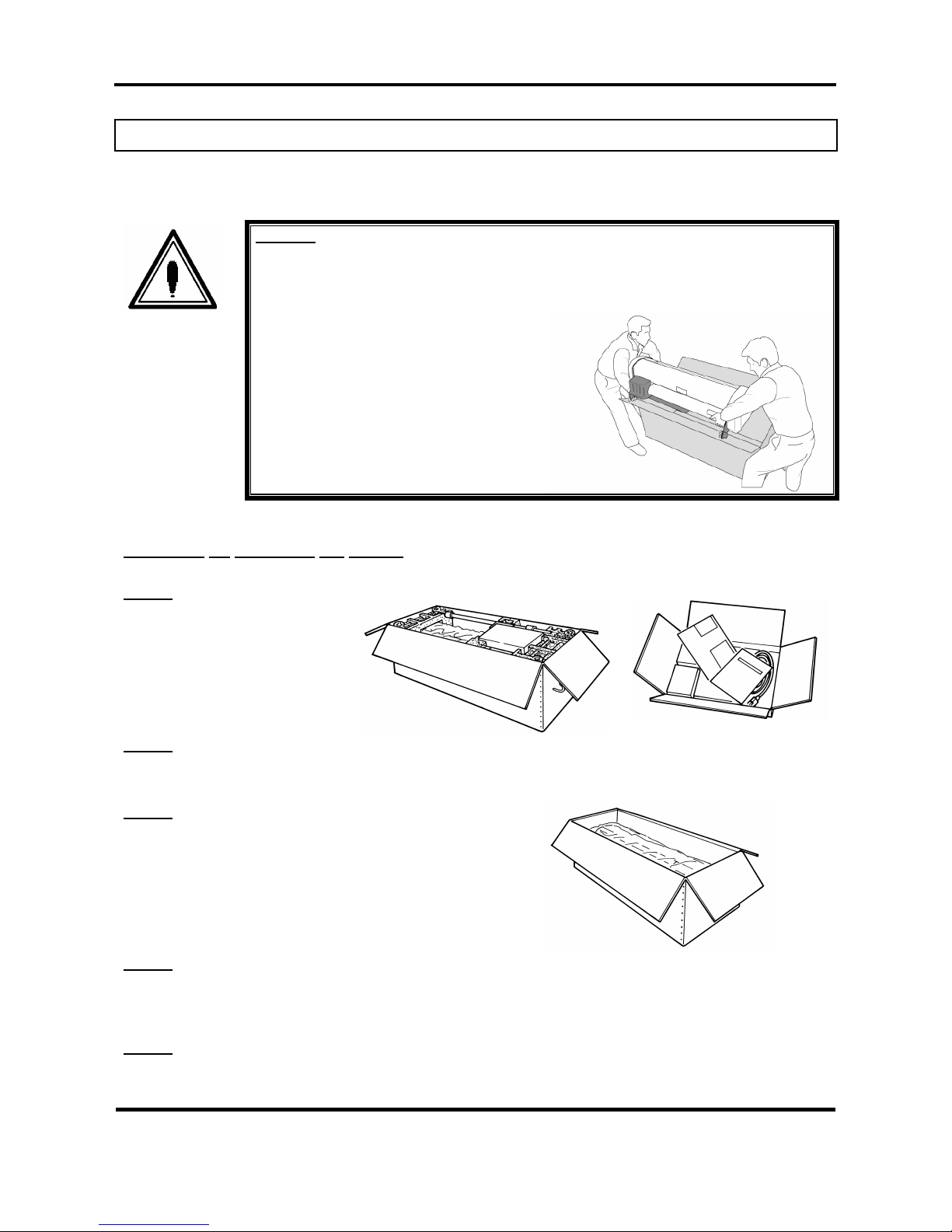
¾ Have two or more people unpack and assemble the printer.
¾ When lifting the printer out of the packing box, be sure to remove the vinyl cover first, then grab the
holding grips on the sides of the printer. Lifting the printer with the vinyl cover on may cause your
hands to slip and drop or damage the printer.
¾ Have two or more people transport the printer.
¾ Ensure that the plug has been disconnected from the power socket when it is not to be used for a long
time.
¾ Earth wires must be connected to wires or terminals that fulfil the conditions below.
o Earth terminals of power sockets
o Earth wires with copper morsel that is at least 650 mm under the ground
¾ Earth wires must be connected to wires or terminals that fulfil the conditions below.
¾ When setting roll media, place it on top of a desk or other flat surface. Setting roll media with the
scroller standing up may damage them.
¾ Keep the printer horizontal during transportation.
¾ Be sure to do the following before attaching options.
o Turn the printer off.
o Unplug the power cord from the socket.
o Unplug cables connected to the printer. Otherwise, damage to the printer or your computer may
occur.
o Remove electrostatic charge from your clothes and body by touching the metal parts of the printer.
o Electronic components such as the memory may malfunction if exposed to an electrostatic charge.
Page 16
Falcon Outdoor Jr. – Operation Instructions
Page 16
PN: MAI-75039
Rev. 1.A – 07/26/05
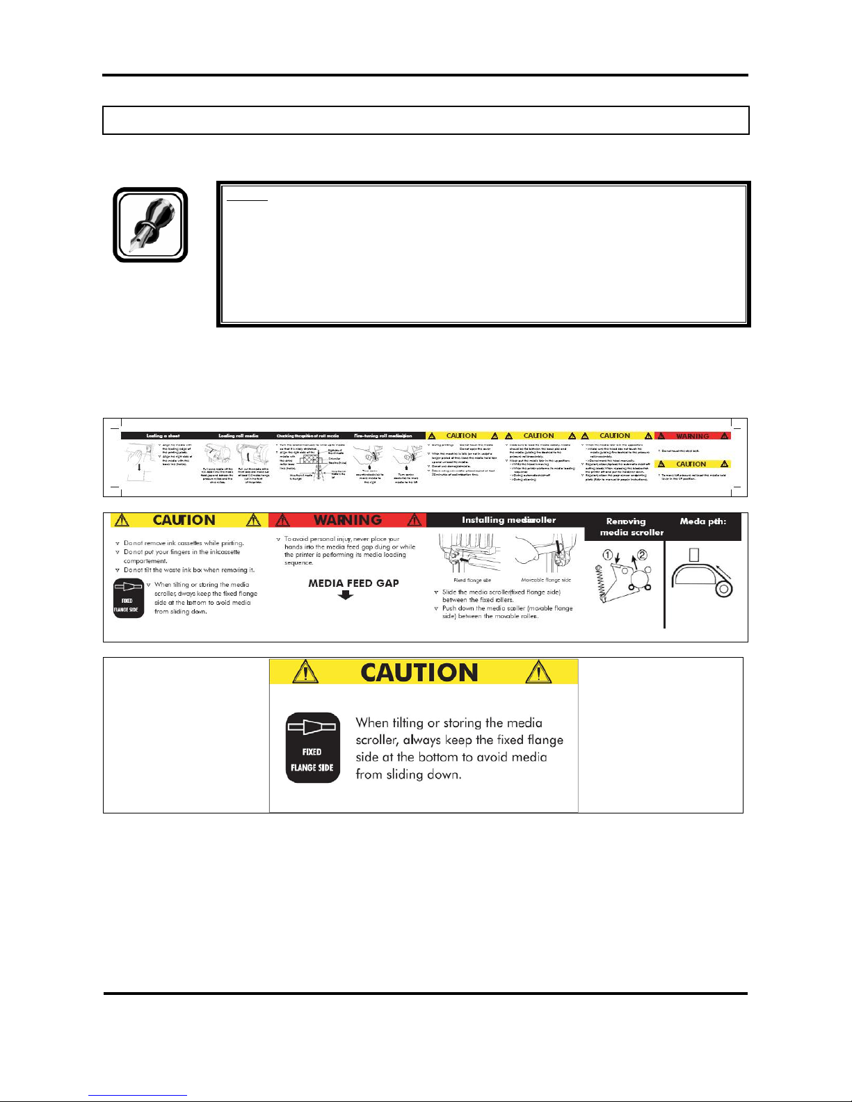
1.4. WARNING LABELS
Be sure to note the following when handling the labels.
Notes :
Make sure that all labels can be recognized. If text or illustrations cannot be seen
clearly, either clean or replace the label.
When cleaning labels, use a cloth with water or neutral detergent. Do not use a solvent
or gasoline.
If a warning label is damaged, lost or cannot be recognized, replace the label. When
replacing warning labels, contact your local MUTOH dealer.
Safety Labels are attached to the internal and external area of the printer to alert you to potentially
hazardous situations or conditions. The following safety labels are used in and on the printer:
Page 17
Falcon Outdoor Jr. – Operation Instructions
Page 17
PN: MAI-75039
Rev. 1.A – 07/26/05
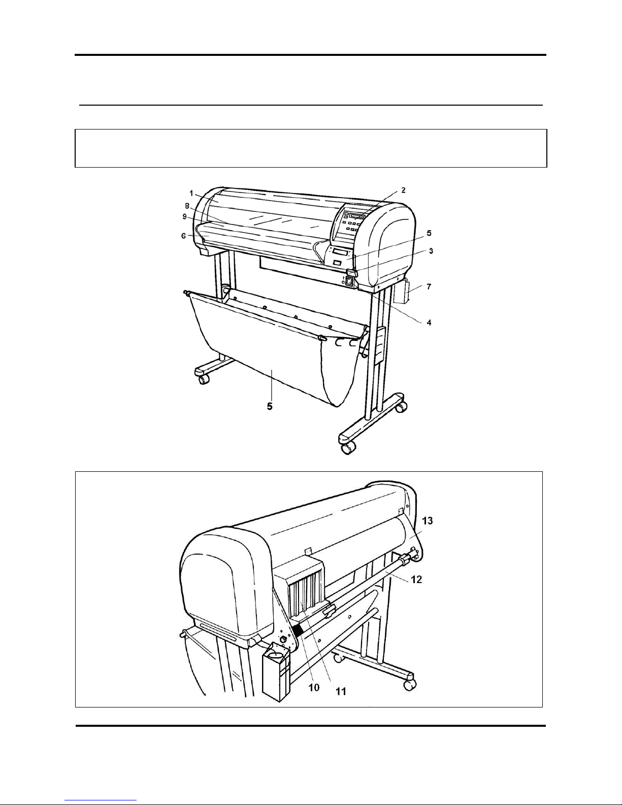
2. PRODUCT OVERVIEW
2.1. GETTING TO KNOW THE PRINTER PARTS AND
COMPONENTS
Page 18
Falcon Outdoor Jr. – Operation Instructions
Page 18
PN: MAI-75039
Rev. 1.A – 07/26/05
N° Part Description
1 Cover
The protective cover protects the action environment. Opening the
cover immediately pauses printing which resumes when the cover is
closed.
2 Operation Panel
Positive touch keyboard with integrated LCD-Display.
3 Media Hold Lever
Lowers / releases pressure rolls to load / unload media.
4 Power switch
ON / OFF Power Switch.
Full shut down takes about 5 seconds.
5 Paper Basket
Media collecting basket prevents finished prints to fall on the floor
when they are sheet-off.
6 Print Plate
The print plate is a firm, flat base which supports the media during
printing.
7 Waste bottle
Collects Eco-Solvent Plus ink flow resulting from: purging, cleaning.
8
9
Paper Guide
The Paper Guide supports the media and incorporates the fixer (8;
heater element below printhead) and dryer (9; heater element)
10 Slip Ring
Prevent that Scroller to slip.
11 Eco-Solvent Plus ink
cassette slots
Hold / detect the Eco-Solvent Plus ink cassettes which are in use.
12 Scroller
Feeds through the roll media core to hold the media.
13 Scroller receiver
Set of 4 wheels which keeps the scroller into place.
Caution:
Do not put anything on the cover.
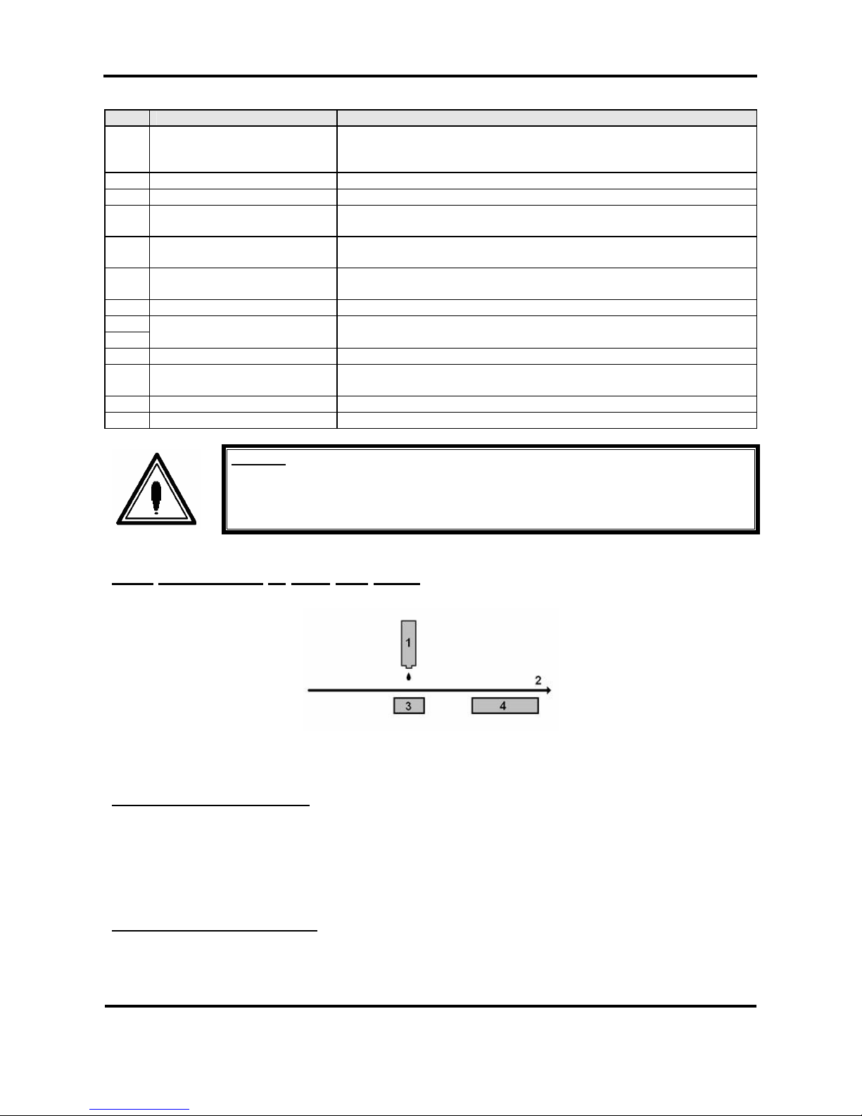
2.1.1
Explanation of fixer and dryer
Print Head
Media Direction
Fixer (Direct Heater)
Post Heater (dryer)
The FIXER will make it possible :
• To overcome the temperature gap between the room and the target printing temperature.
• To establish fast and immediate anchorage of the Eco-Solvent Plus inks onto/into the uncoated
substrate
• To optimize dot gain control on a wide media range
• To limit ink coalescence effect
The DRYER will make it possible
:
• To finalize the fixation process.
• Helps to make the prints touch-dry.
Page 19

Falcon Outdoor Jr. – Operation Instructions
Page 19
PN: MAI-75039
Rev. 1.A – 07/26/05
Page 20
Falcon Outdoor Jr. – Operation Instructions
Page 20
PN: MAI-75039
Rev. 1.A – 07/26/05
3. SETTING UP THE UNIT
3.1. INSTALLATION REQUIREMENTS: SELECTING AN
ADEQUATE PLACE FOR SETTING UP YOUR EQUIPMENT
The location where you set up your equipment is very important. Please see to it that it meets following
conditions:
Power supply:
- Voltage: 200 to 240 VAC or 100 to 120 VAC
- Frequency: 50/60 Hz ± 1 Hz
- Current: < 10 A (110 V)
< 5 A (220 V)
Ambient conditions:
Operating environment
- Temperature: 18°C to 35°C
- Humidity: 20% - 60% non-condensing
- Recommended working environment
Temperature: 22-30°C
Humidity: 40-60%
Storage environment
- Temperature: -10°C to 60°C
- Humidity: 20% - 85% non-condensing
Variation rate
- Temperature: 2°C per hour
- Humidity: 5% per hour
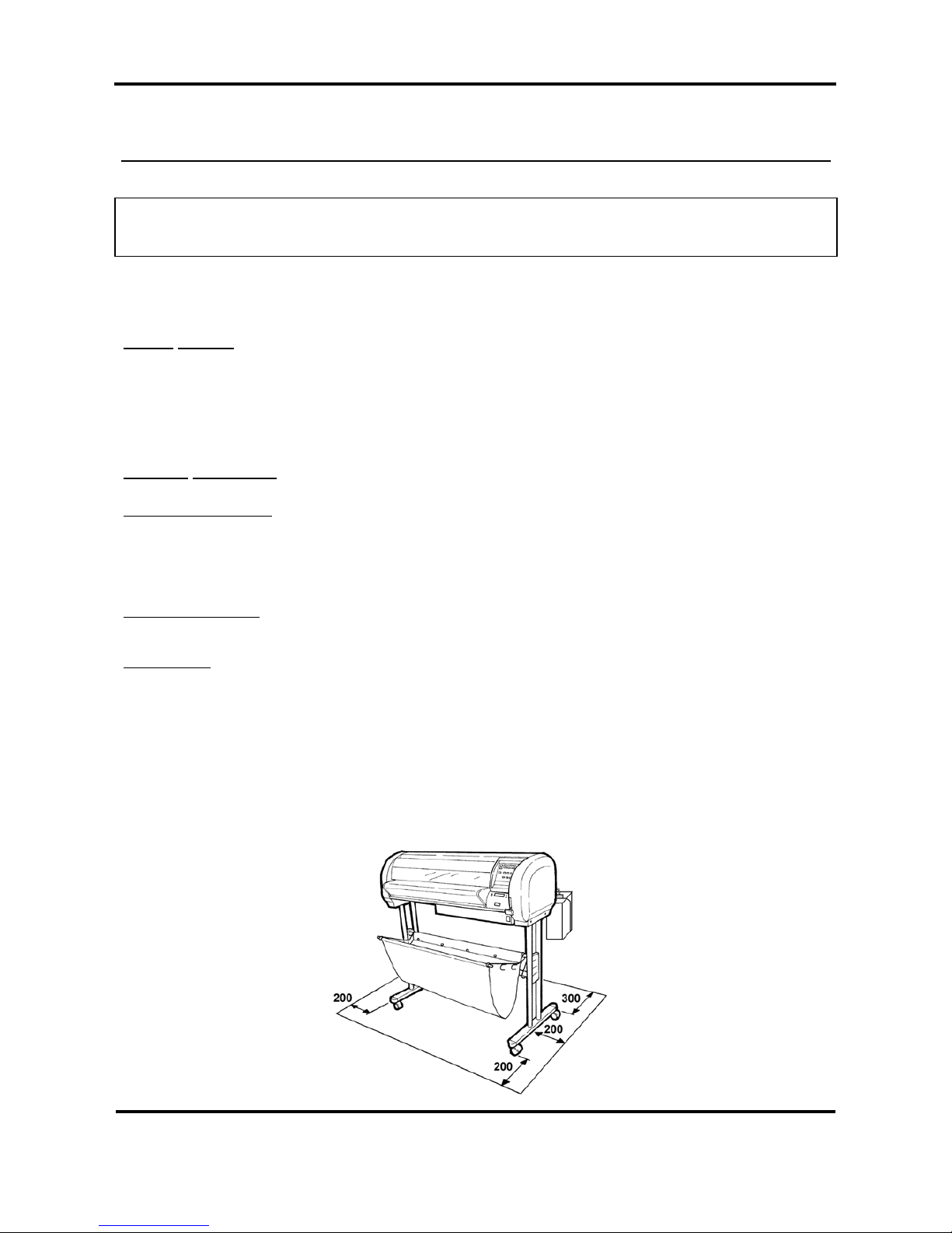
¾ Avoid using your Falcon Outdoor Jr. printer near heating system s, such as stoves or heaters.
¾ Avoid using your printer under strong lighting, such as halogen lamps, light bulbs or direct sun light.
When selecting a place for your printer, leave at least 200 mm in front and at the sides, and 300 mm at the
rear, as shown in the illustration below.
Page 21
Falcon Outdoor Jr. – Operation Instructions
Page 21
PN: MAI-75039
Rev. 1.A – 07/26/05
3.2. WHAT’S IN THE BOX?
What’s in the box ?
¾ Falcon Outdoor Jr. printer unit
¾ Printer stand (packed separately)
¾ 1 Paper scroller (3”) including plastic flanges
¾ 1 Sheet-off knife, pre-installed in head
¾ Media Collection Basket
¾ Starter Software Kit
¾ Scroller Slip Ring
Accessories kit consisting of:
¾ Power cable
¾ Set of Eco-Solvent Plus ink cassettes (CMYK)
¾ User’s guide
¾ Waste bottle
¾ Extra Box with Roll Take-Up System (optional)
¾ Cleaning cartridges
Page 22
Falcon Outdoor Jr. – Operation Instructions
Page 22
PN: MAI-75039
Rev. 1.A – 07/26/05
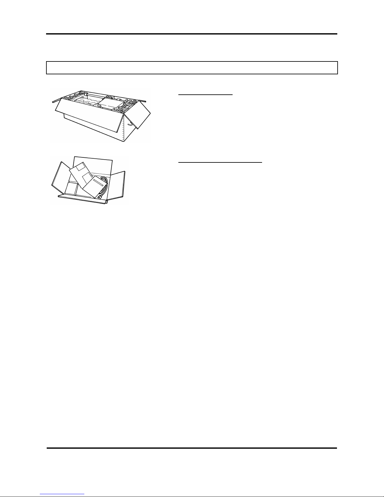
3.3. UNPACKING YOUR FALCON OUTDOOR JR. PRINTER
The printer body and printer stand are packed in two separate boxes. Unpack the printer body first.
Caution:
When unpacking the printer, check whether all parts described in the parts list are
included in the box. Consult your dealer if anything seems to be missing.
Lifting the machine out of the box should
be done by two people.
Protect the printer from shocks.
Do not dismantle the unit.
Procedure for unpacking the printer:
Step 1:
Open the printer body box.
Take out the accessories box and
scroller.
Step 2:
Open the accessories box and take out the User’s guide.
Step 3:
Remove the pieces of foam protecting the printer body during
transportation.
Step 4:
Remove all plastic materials wrapped around the printer.
Step 5:
Open the printer stand box. Check whether all parts described in the parts list are included in the box.
Consult your dealer if anything seems to be missing.
Page 23

Falcon Outdoor Jr. – Operation Instructions
Page 23
PN: MAI-75039
Rev. 1.A – 07/26/05
Page 24

Falcon Outdoor Jr. – Operation Instructions
Page 24
PN: MAI-75039
Rev. 1.A – 07/26/05
3.4. PARTS LIST
3.4.1. Contents of the stand box:
Stand leg (left)
(1 pc)
Stand leg (right)
(1 pc)
Cross bar (2 pcs)
Plastic cover
(2 pcs)
Hexagon wrench
(1 large & 1 small)
Hexagon bolt (long) (4
pcs)
Hexagon bolt (short) (2
pcs)
+ premounted washers
Paper basket
assembly
(1 set)
3.4.2. Contents of the printer box:
Printer unit (1 pc)
3” Scroller (flange on
both sides) (1 set)
Accessories box
Slipring (1 pc)
Page 25

Falcon Outdoor Jr. – Operation Instructions
Page 25
PN: MAI-75039
Rev. 1.A – 07/26/05
3.4.3. Contents of the accessories box:
Cleaning cartridges (4
pc)
Eco-Solvent Plus ink
Cassettes
(C,M,Y,K)
(1 each colour)
Power cable (1 pc)
User’s Guide
Waste bottle + waste
bottle bracket
Page 26

Falcon Outdoor Jr. – Operation Instructions
Page 26
PN: MAI-75039
Rev. 1.A – 07/26/05
3.5. ASSEMBLING THE PRINTER
Caution:
Before lifting the printer body out of the box, make sure to remove all plastic wrapping
materials first, in order to avoid that the machine slips from your hands.
Step 1:
Unpack the stand and assemble it by screwing the left and right stand legs to the cross bars. To do this, use
the 4 long hexagon bolts and the large hex wrench provided. Make sure the leg welding points outwards and
the caster wheels are on the front. After securing the bolts permanently, put on the two plastic side covers.
(See 1 on figure below).
Step 2:
Place the printer onto the stand. The bottom part of the printer body has 4 spherical knobs that exactly fit
into the stand holes. Note that the front side of the stand is the side where the lockable caster wheels are
located. (See 2 on figure below).
Step 3:
Secure the printer body onto the printer stand using the 2 short bolts and the small hexagon wrench
provided. (See 3 on figure below).
Page 27

Falcon Outdoor Jr. – Operation Instructions
Page 27
PN: MAI-75039
Rev. 1.A – 07/26/05
Step 4:
Loosen the wing screw which is fixed to the printing table (4) and remove the metal fixing plate (5) protecting
the printer head during transportation. (See 4 & 5 on figure below). Keep the metal fixing plate and wing
screw, since the printing head needs to be blocked during any transportation of your printer.
Caution:
Take care not to drop the wing screw inside the printer body. Should it fall in, do not
boot up your printer until the wing screw has been safely removed.
Remove the white tape that locks the sheet-off mechanism during transportation
(See 6 on figure below).
Step 5:
Remove the cable block between rail and cover (7).
Remove the lever block (8).
Page 28

Falcon Outdoor Jr. – Operation Instructions
Page 28
PN: MAI-75039
Rev. 1.A – 07/26/05
Step 6:
Assemble the paper basket as follows :
Insert the metal bar into the small sleeve of the cloth basket. Then put on the two metal basket supports to
the left and the right side. Next insert the end caps onto the metal bar. (See 9 on the figure below).
Attach the cloth basket around the lower cross bar of the stand by way of the push buttons. (See 10 on the
figure below).
Secure the paper basket to the printer stand. Fix the front hook of the metal basket supports over the upper
cross bar of the stand, then in-between the two cross bars and finally under the lower cross bar. (See 1 1 on
the figure below).
The extra hooks provided on the metal basket supports are meant to stack your paper basket vertically along
the legs of the printer.
Step 7:
After setting up the printer, wheel it to the desired location and lock the caster wheels.
Page 29

Falcon Outdoor Jr. – Operation Instructions
Page 29
PN: MAI-75039
Rev. 1.A – 07/26/05
3.6. INSTALLATION OF THE WASTE BOTTLE
In the accessories box, you will find the Waste Bottle Bracket together with the Waste Bottle.
After unpacking and assembling the Falcon Outdoor Jr. printer, you must install the Waste Bottle Bracket
with the Waste Bottle.
Important :
Do NOT power on the unit before installation of the Waste Bottle.
Please follow the instructions below to install the Waste Bottle.
Step 1 : Screw the Waste Bottle Bracket onto the Scroller System on the left side standing at the rear of
the unit. (2 screws) (Please refer to picture A on the following page.)
Step 2 : Remove the adhesive tape holding the Waste Tubes to the unit.
Step 3 : Push the big Waste Tube in the hole in the middle of the top of the bracket. Check if the tube is
fixed securely. (Please refer to picture A on the following page.)
Step 4 : For the 2 smaller tubes, do as follows :
¾ Slide the upper plastic ring upwards.
¾ Loosen the lowest plastic ring.
¾ Insert the waste tube in one of the two remaining holes.
¾ Fix the tube by sliding the plastic ring back to the tube.
¾ If necessary lower the upper plastic ring.
¾ Check if the tube is locked securely.
¾ Repeat point 1 to 7 for the other small tube.
1 : plastic rings on small tube 3 : Top Waste Bottle Bracket
2 : big waste tube 4 : Top Waste Bottle
(Please refer to picture A mentioned below.)
Step 5 : Connect the connector of the Waste Bottle Sensor. (Please refer to picture A mentioned below.)
Page 30

Falcon Outdoor Jr. – Operation Instructions
Page 30
PN: MAI-75039
Rev. 1.A – 07/26/05
Picture A :
1. Big waste tube
2. 2 thin waste tubes
3. Screws to mount Waste Bottle Bracket
4. Top Waste Bottle Bracket
1 2 3 4
Page 31

Falcon Outdoor Jr. – Operation Instructions
Page 31
PN: MAI-75039
Rev. 1.A – 07/26/05
4. PREPARING FOR A JOB
4.1. CONNECTING THE POWER CABLE
Step 1 : Make sure the printer’s power switch is turned OFF.
Step 2 : Plug the printer-end of the power cable into the connector at the back of the printer.
Step 3 : Plug the other end of the power cable into an electrical outlet of the correct voltage and with a
proper grounding.
Power supply:
• Voltage:
100-120V 200-240V
• Frequency:
50/60 Hz 50/60 Hz
• Current:
6.8A 3.4A
Note:
When you turn off the power, please note that your printer needs about five seconds to
perform its shut down sequence.
To this end, wait for at least five seconds to switch the printer on again.
The disconnect device is the plug on the power supply.
Page 32

Falcon Outdoor Jr. – Operation Instructions
Page 32
PN: MAI-75039
Rev. 1.A – 07/26/05
4.2. CONNECTING THE INTERFACE CABLE
Caution:
When connecting the printer to your computer, make sure that both your printer and
your computer are switched OFF.
Note:
For optimum output, please use a cable recommended by Mutoh.
The printer can use the Centronics interface (IEEE1284 compatible, Nibble, ECP). Connect to the printer as
shown in the following diagram with an interface cable (option) for the connection system you will use.
Connect to the host computer with another interface cable.
Note:
The use of an unnecessary long cable may influence your data transmission. Therefore,
keep your interface cable as short as possible.
An Ethernet board RJ-ETH14TX (for networking) is available as an optional extra.
4.2.1. Tips to use high-speed ECP parallel communication
¾ If the parallel port setting on the printer is set to BI CENTRO (See Menu Mode Operation – Menu
Structure Overview) your printer is ready for high-speed bi-directional communication.
¾ In order to be able to use this high-speed mode without problems please note:
Computer Bios for parallel port should be set to ECP
Only use a shielded and balanced parallel cable, which is IEEE 1284 compliant.
If your RIP software is protected with a hardware lock (dongle), which needs to be placed on the
parallel port, it is best to have available 2 parallel ports.
• One port to connect: hardware lock, scanner, external drive or CD-ROM,…
• One port (ECP) directly connected to the printer.
In case either of the above mentioned topics is not respected you may encounter all kinds of printer artefacts
such as: unexplainable error messages, sheet-off during printing, unexpected media feed during printing,
etc…
If this occurs, switch your system to unidirectional parallel communication.
Set print parallel port to Mode > CENTRO
Set computer parallel port Bios to SPP or EPP
The data transfer will then slow down and the artefacts will disappear. Before switching back to the highspeed bi-directional parallel mode, have your computer system examined closely by a trained computer
technician.
Page 33

Falcon Outdoor Jr. – Operation Instructions
Page 33
PN: MAI-75039
Rev. 1.A – 07/26/05
QUICK START FOR SEH AND FALCON OUTDOOR PRINTERS
SEH PRINTSERVER AND INTERCON NETTOOLS SETUP AND DIAGNOSTIC
FEATURE (FILE DOWNLOAD)
TO INSTALL AN SEH BOX FOR ANY OF THE FALCON OUTDOOR SERIES
PRINTERS FOLLOW THESE STEPS.
10. DO NOT connect the SEH box to the printer at this time.
11. Put the CD in the computer, if ‘autorun’ starts then follow the info to install “English” and choose ‘Intercon
NetTools’ then Go to 9. If ‘autorun’ does not start then proceed.
12. Click – My Computer
13. Right click on the CD icon
14. Select “Explore” from menu
15. Double click on the “NetTool” folder
16. Double click on “Windows” folder
17. Double click “NetTool” Setup
18. Follow prompts to complete installation
• Connect the SEH box ONLY to the network cable, DO NOT attach to the printer at this time. Use a
crossover cable if you are connecting directly to a computer. Use a standard cable if you are connecting
using a ‘switch’, ‘router’ or ‘hub’. Crossover direct connection should not be used for production work.
• After completing 1 – 9 above, launch “InterCon – NetTools” from the desktop icon or find InterConTools
in your Programs folder.
• Double click on the IP address (most likely all zeros). (Loading properties menu should open).
• Select TCP/IP tab on the left.
• Remove the ‘checks’ in the boxes from all items except ARP/Ping. Specifically DHCP.
• ‘Check’ the TCP/IP box and Enter your IP address and submask then click OK. A Gateway is not
required.
CAUTION: The IP address must match all three of the first 3 triads (sets of three numbers) and the only
difference is the last ‘triad’ where the printer is usually ‘1’ number different from the computer. All four triads
of the SUB NET mask must match exactly as well.
• Select ‘rebuild’ on the Intercon NetTools menu. Verify the IP address line changes to your entered
address. The printer icon should show a red X through it.
• Connect the SEH box to the printer LPT port. The red X should come off when the printer is powered
ON. Click the Refresh or Rebuild buttons to make it change if it doesn’t automatically refresh itself.
Notice that the SEH utility now shows the name of the printer.
Print server is now configured for your network and IP address.
• Setup up your RIP software for the IP address of the SEH box.
Page 34

Falcon Outdoor Jr. – Operation Instructions
Page 34
PN: MAI-75039
Rev. 1.A – 07/26/05
DIAGNOSTIC ASSISTANCE USING ‘FILE DOWNLOAD’ FEATURE OF THE SEH BOX.
Both the WEB interface (IP address in browser) or Intercon Nettools have the ability to transfer a file directly
to the IP address. This is important as sometimes the problem in the print is RIP related and if the RIP is
used to create a ‘test’ file then it could have the problem in it.
Mutoh provides a ‘test print’ file for each model of printer. For the Falcon Outdoor or Falcon Outdoor Junior
these files are a low ink density Diagonal nozzle check pattern designed to show whether ‘Step Adjustment’
is correct or not. (ignore the Distance Adjustment feature on the FO series). Once the ‘Step Adjust’ is dialed
in then images printed with the correct profile should be able to be printed.
Each of the SEH options have a ‘Download / file’ section where you will be prompted for a file. Locate the
‘testprint’ file that is appropriate
Please realize that a ‘light band’ can be either missing / misdirected nozzles or that Step Adjust is too high.
Confirm that nozzles are firing and then start this procedure for Micro Banding.
A ‘dark band’ can be from either Step Adjust being too low or it can be from the platen heater not being hot
enough. For this reason it is suggested that if no light band is showing then change the Step adjust higher to
create a light band. Then reduce the number in small steps until either you have no band or a slight dark
band remains. Once you reach this point adding ‘heat’ to the platen should then minimize the banding to an
acceptable amount for solvent printing.
Remember
5. Check nozzles first. Clean as required.
6. Dial out the light and first. Create a light band if necessary.
7. For the bark band that remains after dialing out the light band, start by increasing the platen heat in
small steps.
8. If a small dark band remains after step 3 then Adjust the ‘Step Adjust’ a little lower.
If increasing the platen heat does not remove the dark band then it may be that there is too much ink being
laid down so the RIP profile may need to be adjusted. Call your dealer for assistance with this RIP profile
possibility.
STEP ADJUSTMENT ‘MICRO-BANDING ELIMINATION ON FALCON OUTDOOR’
The nominal paper movement accuracy is ± 0.1 percent, or ±1 mm per meter of moving distance. Different
media types may show different behavior and when the paper movement error exceeds the target
specification, banding can occur. This banding can take the form of either thin dark or light horizontal bands.
If the above happens, these bands will occur in both bi-directional and unidirectional print modes. Thin da rk
bands indicate that the printer firmware is under-compensating and that print swaths are overlapping.
Alternatively, thin light lines indicate that the printer firmware is over-compensating, and that print swaths are
not far apart.
The media feed micro ‘step adjustment’ feature gives the user the ability to set the step compensation
algorithm. To eliminate micro-banding, you can enter a positive or negative percentage of compensation, (±
3.00 percent), in 0.01 percent increments.
A positive value will extend the step and compensate for overlapping print swaths; a negative value will
shorten the step and compensate for non-butting print swaths. Some trial and error testing is typically
required to find the optimum value for any given media type.
Page 35

Falcon Outdoor Jr. – Operation Instructions
Page 35
PN: MAI-75039
Rev. 1.A – 07/26/05
Plot OK
Step 1:
To enter the Menu system, press the [MENU] key.
* Menu * Command >
Step 2:
The key contents change to the yellow section on the outside of the
control panel. Bring up the “Function” menu by pressing the [Menu
up] key or [Menu Down] key.
* Menu * Function >
Step 3:
Press the [ENTER] key to enter the “Function” menu and shift to the
next level.
Step Adjustment : Change
Step 4:
Bring up the “Step Adjustment” item by pressing the [Menu up] key
or [Menu Down] key.
Step Adjustment : Clear
Step 5:
Press the [Value/+] or [Value/-] key to select “Change” or “Clear” and
press ENTER.
Step Adjustment : 0.00%
Step 6:
When pressing “Change”, enter the new value using the [VALUE/+] /
[VALUE/-] keys. Using the [MENU UP] / [MENU DOWN] keys,
you can select which digit you want to change. The value can be
changed in 0.01% increments.
Press [ENTER] to confirm the new value.
Step Adjustment : Change
Step 7:
If no other items are to be changed, press the [BACK] key.
* Menu * Function >
Step 8:
Do not press any other keys for 3 minutes or press [BACK] key
Plot OK
Step 9:
The permanent ONLINE-status display is restored.
Note:
To find the optimum correction value for a certain media, you will need to go through
a series of test cycles. Preferably send to the plotter a small test image such as a
neutral grey square (between 50% and 70% Grey) and check the micro-banding as
described above. Make a note of your correction value for a certain media type, as
the required value will always be the same for this media type.
Note:
Before using this function, always perform a nozzle-check to see if all nozzles are firing
correctly. Nozzles which are not firing or misfiring might mislead you when entering
correction values.
Page 36

Falcon Outdoor Jr. – Operation Instructions
Page 36
PN: MAI-75039
Rev. 1.A – 07/26/05
4.3. LOADING ECO-SOLVENT PLUS INK CASSETTES (FIRST
TIME)
Important :
Before installing Eco-Solvent Plus ink cassettes in your new Falcon Outdoor Jr.
printer, it is necessary to clean the Falcon Outdoor Jr. with special Eco-Solvent
Plus Cleaning Liquid.
Before transportation (e.g. service) it is necessary to clean the Falcon Outdoor
Jr. (which used Eco-Solvent Plus ink) with special Eco-Solvent Plus Cleaning
Liquid.
When the machine returns or is installed at another place, perform again a
cleaning with the special Eco-Solvent Plus Cleaning Liquid.
Please only use the Eco-Solvent Plus Cleaning liquid. Using other cleaning
cassettes will result in clogging of ink in the machine. As a result all internal
ink-passages must be replaced.
Note :
When loading Eco-Solvent Plus ink for the first time, please make sure to have four
Eco-Solvent Plus Cleaning liquid cassettes.
Before installing Eco-Solvent Plus ink cassettes in your new Falcon Outdoor Jr. printer, it is necessary to
clean the Falcon Outdoor Jr. with special Eco-Solvent Plus Clean ing Liquid.
To do so, please follow the instructions mentioned below.
Step 1:
Power ON the unit.
Step 2:
Slide the four Eco-Solvent Plus Cleaning liquid cassettes into their cassette
position. Automatic detection of cleaning cassettes occurs due to label
recognition.
Step 3:
Press the [VALUE +] key or [VALUE -] key to select “Yes” and pre ss
ENTER.
Note :
Please note that the Falcon Outdoor Jr. printer has two print heads (K, CMY). A head
wash cycle is done per print head. This means that the first head wash cycle is
performed for the K print head only, and then a head wash cycle is performed for the
CMY print head.
[YMCK] discharge
Wash: Black&Colour
Page 37

Falcon Outdoor Jr. – Operation Instructions
Page 37
PN: MAI-75039
Rev. 1.A – 07/26/05
Step 4:
The unit is cleaning the K print head.
.
Step 5:
Remove the Black (K) Eco-Solvent Plus Cleaning Liquid cassette.
Note :
Only remove the Black (K) Eco-Solvent Plus cleaning liquid cassette (Not all four Eco-
Solvent Plus cleaning liquid cassettes). Removing all Eco-Solvent Plus cleaning liquid
cassettes could cause the printer to lock-up. If this is the case, please re-insert the
Eco-Solvent Plus cleaning liquid cassettes into the CMY cassette slots to recover the
ink load procedure.
Step 6:
The unit is cleaning the CMY print heads.
Step 7:
Remove the Eco-Solvent Plus Cleaning Liquid cassette from the CMY
slots.
Step 8:
The rest of the cleaning fluid in the printer unit is discharged when cleaning
cassette is removed.
Step 9:
Empty the waste ink box from the printer.
Step 10:
Insert the four Eco-Solvent Plus ink cassettes one by one in the correct
slot.
Step 11:
Eco-Solvent Plus ink is being loaded into the ink supply system (tubing +
heads).
Note :
Please wait after loading Eco-Solvent Plus Ink for about 1 hour before start printing.
The printer is now ready to print.
Head Wash
Remove Bk Wash Cart
Head Wash
Remove Co Wash Cart
Head Wash
Change Waste ink
[CMYK] discharge
Ink refill 4M
Page 38

Falcon Outdoor Jr. – Operation Instructions
Page 38
PN: MAI-75039
Rev. 1.A – 07/26/05
4.4. LOADING MEDIA
4.4.1. General recommendations with regard to printer media
¾ For best quality output and printing results on your Mutoh Falcon Outdoor Jr. Eco-Solvent Plus printer, it
is recommended to use MUTOH media.
¾ For printing onto uncoated media, the temperature that can be reached on top of the media is important
to obtain the right output quality and ink fixation. Note that the temperature reached on top of the media
depends on the heater settings, the heat capacity of the media which is used and the exposure time (=
time the media is exposed to heat), which is influenced by the output mode, printing width and ink setup.
¾ Lower cost self-adhesive PVC media are produced with a normal clay coated paper backing. This
backing paper tends to dry out because of the heating and may start to cockle. This phenomenon can
be overcome by reducing the heating temperature or by selecting a media with a PE-coated backing
paper.
¾ It is strongly recommended to acclimatize your media before printing on it. Ideally, bring the media rolls
in the neighbourhood of the printer 24 hours on beforehand. Bringing in cold media and printing on it
usually results in inferior output quality because of the big temperature gap that needs to be overcome.
We recommend a working environment with a temperature between 22° C and 30° C and a humidity
between 40% - 60% (without condensation).
¾ We recommend you to wear cotton gloves to avoid fingerprints on the media.
¾ Always make sure that you are printing on the correct side (printable side) of the media.
4.4.2. Loading cut sheet media
Step 1:
Open the cover and verify that the hold lever is in the UP position.
Step 2: Selecting the media
Press the Media-key to select media loading sequence with roll
take-up system (Both LEDs ON).
By pressing the key you will see the LEDs alternate between three
choices (sheet, roll and take-up). Now select roll take-up loadi ng
sequence (both LEDs ON).
Now select sheet
Note:
When making the wrong media selection choice by selecting roll when a cut-sheet is
being loaded, the printer will give the roll media end warning when the end of the cutsheet is reached, and printing will not be finished normally.
Step 3: Installing the media
Insert the media, which has already been acclimatized, between the pressure roller system and the drive
Page 39

Falcon Outdoor Jr. – Operation Instructions
Page 39
PN: MAI-75039
Rev. 1.A – 07/26/05
roller.
Step 4:
Align the right side of the media with the base line (holes), as shown in the figures.
Align the media with the leading edge of the printing plate.
Align the right side of the media with the baseline holes. You are
allowed about 5 mm of play to the right and left of the centre of
the base line holes.
Please examine the position of the left side of the media and compare it with the illustrations below.
There is not enough clearance between the media edge and the
pressure roll (less than 5 mm), which may cause a media jam or
damage if the media slightly shifts during printing.
Media is set correctly, it is held down completely by the pressure
roll. Even slight shifting will not cause media damage or a
media jam.
Media is set correctly. There is at least 5 mm clearance
between the pressure roller and the media edge.
Important:
The base line is just a guideline. You are allowed about 5 mm of play to the left
and right of the centre of the base line holes. This play allows you to correctly
load the media as described under step 4.
Page 40

Falcon Outdoor Jr. – Operation Instructions
Page 40
PN: MAI-75039
Rev. 1.A – 07/26/05
Step 5:
Lower the media hold lever by tilting it down(wards).
Notes:
Always remove the roll media and scroller from the scroller receiver before loading a cut
sheet.
Install your media straight. If you do not do this, the printer might misread the actual
media size, resulting in abnormal printing.
When the roll media indicator is ON while a cutsheet is loaded, this indicates a media
selection error
and printing will not be finished normally.
You can install a cut sheet both in the horizontal and in the vertical direction, except for
A0 size cut sheets. This size can only be installed in the vertical direction.
The media has a printing side and a non-printing side.
If you print on the non-printing side, this may influence the quality.
The printable side is normally whiter.
Step 6:
Close the cover. The head starts moving automatically to detect the media size.
Step 7:
When media is loaded correctly and the printer is ready to receive data, the display shows the message:
Step 8:
Removing the media
Open the cover, tilt the media hold lever UP, and remove the media.
Note:
During plotting, media detection, cutting and cleaning always keep the media hold lever
down.
If the print head is not situated at the maintenance position, the media hold lever cannot
be lifted UP.
Do not move the print head while the hold lever is UP.
Roll Media End
Media Initialization
Plot OK
Page 41

Falcon Outdoor Jr. – Operation Instructions
Page 41
PN: MAI-75039
Rev. 1.A – 07/26/05
4.4.3. Loading roll media
Step 1 : Open the cover, check that the head is in a position where it will not touch the media keeper
blade and put the hold lever up.
Step 2 : Selecting the media
Press the Media-key to select media loading sequence with roll
take-up system (Both LEDs ON).
By pressing the key you will see the LEDs alternate between three
choices (sheet, roll and take-up). Now select roll take-up loadi ng
sequence (both LEDs ON).
Now select roll
Note :
When making the wrong choice by selecting cut-sheet when a roll is loaded, the printer
will pull off the maximum cut-sheet length, searching the back edge. Finally the printer
will report a media search error.
Step 3 : Take your roll of media.
Step 4 : Remove the movable flange from the scroller by
pulling it off.
Step 5 : Load the media over the scroller
Turn the roll media as shown in the diagram and pass it over the scroller until the media tube fits
firmly over the fixed flange. Replace the movable flange on the scroller and fit it firmly into the
media tube.
Page 42

Falcon Outdoor Jr. – Operation Instructions
Page 42
PN: MAI-75039
Rev. 1.A – 07/26/05
Note:
Do not drop the media roll over the scroller as this might damage the scroller end caps.
All Mutoh recommended roll media are rolled up with the printable side facing the
outside, so that you can load the roll media easily.
When the cut sheet indicator light is ON when loading a roll, the printer will display a
media search error after feeding the media for about 3m.
Step 6 : Installing the scroller slip ring
Install the scroller slip ring onto the scroller. Slide the scroller slip ring on the left side of the
scroller (side with fixed flange).
Step 7 : Installing the scroller
Install the scroller as follows:
Stand at the back side of the printer, holding the scroller with the fixed flange side in your left
hand. Slide the scroller (left side) into the scroller receiver, as shown in the illustration. Push the
scroller (Right side - movable flange side) down into the right scroller receiver. You will noti ce it
dropping nicely into place.
Step 8 : Locking the scroller slip ring
Lock the scroller by sliding the scroller slip ring onto the scroller rollers. The scroller slip ring will
prevent unwinding of the roll media from the scroller when roll media is still not loaded in the
machine.
Page 43

Falcon Outdoor Jr. – Operation Instructions
Page 43
PN: MAI-75039
Rev. 1.A – 07/26/05
Step 9 : Loading roll media
Pull some media off the roll, feed it into the media feed gap and
between the pressure rollers and the drive roller.
Pull out the media at the front side and make sure at least 0.5
meters hangs out in front of the printer.
Caution:
When you load roll media from the back, be careful not to hurt yourself by touching the
pressure roll system.
Step 10 : Checking the position of roll media
Turn the scroller by hand and wind up several turns of roll media. As you wind up the media, check the
relative positions of the drive roller on the right and the right hand edge of the roll media. It is normal if with
the roll media pulled tight, the portion that is being wound and the portion that was unwound are straight and
the right hand side edge of the media is on the guide line. If this is not the case, adjust the position of the roll
media in accordance with step 9.
Guide line (holes) can be seen Guide line (holes) is hidden
Step 11 : Fine-tuning the roll media position
If the guide line (holes) can be seen, the roll media must be moved to the right.
If the guide line (holes) is hidden, the roll media must be moved to the left.
Turn the scroller receiver screw counter -clockwise to move
the roll media to the right (when standing in front of the
printer).
Page 44

Falcon Outdoor Jr. – Operation Instructions
Page 44
PN: MAI-75039
Rev. 1.A – 07/26/05
Turn the scroller receiver screw clockwise to move the roll
media to the left (when standing in front of the printer).
Important:
The guide line (holes) is a guide.
There is a possibility of a jam if the pressure roller is not holding the left edge of
the media and the pressure roller is near the right edge. Either hold the left edge
of the media completely with the pressure roller or slide it so that the pressure
roller is about 5 mm away from the right edge of the media and the right edge of
the media within 5 mm to the left or right of the guide line (holes).
Step 12 : Check if the roll media has been installed correctly.
Lower the media hold lever and close the cover.
The head moves automatically and detects the media size.
The display will show the following message during loading:
After performing its media loading sequence (± 30 seconds) the printer displays the following message:
Important:
If the roll media has not been fed straight or incorrectly, messages such as,
“media error” or “media jam error” are shown on the display. If this is the case,
reload the media following the instructions above.
ConfirmPaperKind
Plot OK
Page 45

Falcon Outdoor Jr. – Operation Instructions
Page 45
PN: MAI-75039
Rev. 1.A – 07/26/05
Step 13 : During the media detection sequence, check if the media runs straight. After media detection,
check the position of the right side of the roll media. If the position is almost on the same line as
it was before closing the cover, media loading was performed successfully. If after the media
detection sequence, the roll media position is not on the same position as it was before closin g
the cover, repeat the instructions from steps 8 and 9 for installing the media.
Note:
Removing roll media
Step 1:
After printing, open the cover, tilt the media hold lever UP and wind up the roll media.
Step 2:
Stand behind the printer. Unlock the scroller receiver
by pressing the lock lever down. You can now lift the
right side of the scroller and remove it from the printer.
Step 3:
Remove the roll media by gently pushing the roll media off the scroller via the moveable
flange side.
At no times drop the scroller end-caps on the floor as this might damage the scroller
end-caps and reduce media tracking or loading problems.
Important:
• Please make sure not to load media that is wider than 954 mm (37,55”).
The maximum width that you can load is indicated with a sticker on left
most side of the printing table.
• Loading wider media may cause the head carriage to bump against the left
end plate and cause an error. In this case you will need to power cycle the
printer before you can continue.
Page 46

Falcon Outdoor Jr. – Operation Instructions
Page 46
PN: MAI-75039
Rev. 1.A – 07/26/05
4.4.4 Loading media in combination with the Roll Take-Up System.
Step 1 : Open the cover and put the hold lever in the UP position by tilting it up(wards).
Step 2 : Selecting roll take-up system
Press the Media-key to select media loading sequence with roll
take-up system (Both LEDs ON).
By pressing the key you will see the LEDs alternate between
three choices (sheet, roll and take-up). Now select roll take-up
loading sequence (both LEDs ON).
Step 3 : Take an empty cardboard core. Slide the empty cardboard roll over the scroller of the roll take-
up system.
Note :
Notice that one flange is fixed. A warning sticker is attached near the flange. Do not
remove this flange.
Step 4 : Take your roll of media.
Step 5 : Remove the moveable flange from the
scroller by pulling it off.
Movable Flange
Step 6 : Load the media onto the scroller.
Feed the scroller through the media core.
Gently but firmly press the roll media over the fixed flange.
Slide the moveable flange over the scroller and firmly press the flange inside the roll media core.
Page 47

Falcon Outdoor Jr. – Operation Instructions
Page 47
PN: MAI-75039
Rev. 1.A – 07/26/05
1 = Fixed flange
2 = Media winding direction
Note :
Do not drop the media roll over the scroller as this might damage the scroller end caps.
Damaged end caps may cause media tracking problems.
All Mutoh recommended roll media are rolled up with the printable side facing the
outside, so that you can load the roll media easily.
Step 7 : Installing the scroller slip ring
Install the scroller slip ring onto the scroller. Slide the scroller slip ring on the left side of the
scroller (side with fixed flange).
Step 8 : Installation of the scroller.
Install the scroller as follows :
¾ Stand at the back side of the printer, holding the scroller with the fixed flange side in your left hand.
¾ Slide the scroller (left side) into the scroller receiver, as shown in the illustration.
¾ Push the scroller (Right side – movable flange side) down into the right scroller receiver. You will
notice it dropping nicely into place.
Step 9 : Locking the scroller slip ring
Lock the scroller by sliding the scroller slip ring onto the scroller rollers. The scroller slip ring will prevent
unwinding of the roll media from the scroller when roll media is still not loaded in the machine.
Page 48

Falcon Outdoor Jr. – Operation Instructions
Page 48
PN: MAI-75039
Rev. 1.A – 07/26/05
Page 49

Falcon Outdoor Jr. – Operation Instructions
Page 49
PN: MAI-75039
Rev. 1.A – 07/26/05
Step 10 : Loading roll media.
Pull some media off the roll, feed it into the media feed gap and between
the pressure rollers and the drive roller.
Pull out the media at the front side and make sure at least 0.5 meters
hangs out in front of the printer.
Caution :
When you load roll media from the back, be careful not to hurt yourself by touching the
pressure roller system.
Step 11 : Checking the position of roll media.
Turn the scroller by hand and wind up several turns of roll media. As you wind up the media, check the
relative positions of the drive roller on the right and the right hand edge of the roll media. It is normal if with
the roll media pulled tight, the portion that is being wound and the portion that was unwound are straight and
the right hand side edge of the media is on the guide line. If this is not the case, adjust the position of the roll
media in accordance with step 9.
Guide line (holes) can be seen Guide line (holes) is hidden
Step 12 : Fine-tuning the roll media position.
If the guide line (holes) can be seen, the roll media must be moved to the right.
If the guide line (holes) is hidden, the roll media must be moved to the left.
Turn the scroller receiver screw counter -clockwise to move
the roll media to the right (when standing in front of the
printer).
Page 50

Falcon Outdoor Jr. – Operation Instructions
Page 50
PN: MAI-75039
Rev. 1.A – 07/26/05
Turn the scroller receiver screw clockwise to move the roll
media to the left (when standing in front of the printer).
Important:
The guide line (holes) is a guide.
There is a possibility of a jam if the pressure roller is not holding the left edge of
the media and the pressure roller is near the right edge. Either hold the left edge
of the media completely with the pressure roller or slide it so that the pressure
roller is about 5 mm away from the right edge of the media and the right edge of
the media within 5 mm to the left or right of the guide line (holes).
Step 13 : Before lowering the media hold lever, hold the media on the front side and turn the media feeding
scroller slightly backward, making sure that there is an even tension across the f ull media width.
Lower the media hold lever and close the cover. The head moves automatically and will search
for the left and right edge of the media being loaded.
Important :
If the roll media has not been fed straight or incorrectly, messages such as “Stuck
Media error” or “Take out paper” are shown on the display. If this is the case,
reload the media following the instructions mentioned above.
Step 14 : In the MENU “Function” of your printer, set media cut to OFF.
Page 51

Falcon Outdoor Jr. – Operation Instructions
Page 51
PN: MAI-75039
Rev. 1.A – 07/26/05
Step 15 : Feed the media forward by pressing the SHIFT &
ADVANCE keys simultaneously until the media
reaches the cardboard core on the take-up system.
Step 16 : Fix the media on the cardboard core by means of self-adhesive tape strips in the middle and on
the left and right side.
Note :
First attach the middle of the media on the cardboard core to avoid slipping of the media.
Step 17 : Feed the media slightly forward (using SHIFT & ADVANCE) and wind it up on the take-up
system.
Now you are ready to start printing.
Once the printer has printed as much as shown on the figure below, the senso r s will be activated and the
take-up system will start winding up the media.
Once your print is finished and dry you can wind up your print via a manual feed button.
If you want to sheet off the print push the cancel button for 2 seconds and confirm the sheet-off request.
If you want to wind up or wind off your print you can do this via the forward / reverse button.
Page 52

Falcon Outdoor Jr. – Operation Instructions
Page 52
PN: MAI-75039
Rev. 1.A – 07/26/05
4.4.5. Eco-Solvent Plus Media List
Mutoh offers media specially targeted for outdoor applications, media aimed for indoor applications where
long-term indoor lifetime of the output is required and media specially engineered for makin g colourful
banners.
Together with your Falcon Outdoor Jr. series printer, you will receive a sample roll of one of the Mutoh EcoSolvent or Eco-Solvent Plus media and a CD-ROM containing pre-ripped data, allowing you to test the EcoSolvent and Eco-Solvent Plus media.
On the CD-rom you will find more information on how to correctly use the Eco-Solvent media or Eco-Solvent
Plus media.
More media information, media specification sheets and free of charge media profiles for Mutoh’s in-the-bo x
software are at all times accessible via Mutoh’s website under
http://www.mutoh.be
For pricing and availability details, please contact your Mutoh reseller.
Page 53

Falcon Outdoor Jr. – Operation Instructions
Page 53
PN: MAI-75039
Rev. 1.A – 07/26/05
4.5. ADJUSTING HEAD HEIGHT.
Depending on the media type and media thickness used, it is possible to adjust the printer’s printhead height
accordingly 1.5 mm to 2.0 mm (± 0.15 mm).
The head height can be adjusted using the lever on the left side of the head (please refer to the picture
mentioned above).
When the lever is put in horizontal position (turn counter clockwise) the head is in his highe st positio n : 2.0
mm
When the lever is turned clockwise, the head is in his lowest position : 1.5 mm.
The lever can only be put in two positions, there are no intermediates.
Typical use :
LOW HIGH
Photo quality output on photo paper type media
(Mutoh Photo Great Piezo Media, Paper, Vinyl,
Synthetic paper,…)
Thick media or media with fibres (Fabrics) which may
touch the printhead during printing.
(Canvas, Art Paper, Cardboard,…)
Page 54

Falcon Outdoor Jr. – Operation Instructions
Page 54
PN: MAI-75039
Rev. 1.A – 07/26/05
Page 55

Falcon Outdoor Jr. – Operation Instructions
Page 55
PN: MAI-75039
Rev. 1.A – 07/26/05
5. HANDLING THE PRINTER
5.1. GUIDED TOUR AROUND THE OPERATION PANEL
Your printer is equipped with a direct access operation panel, meaning that all frequently use d functions can
be addressed directly from the keyboard.
Nr. Key Description
1. Data LED :
The DATA LED monitors DATA status :
¾ LED ON
indicates data is being received.
¾ LED FLASHING
means data is being processed.
2. Error LED :
The ERROR LED is ON
after an ERROR has occurred, to indicate
a possible hazardous situation. The LED will go out if the error is
corrected or after pressing the [CANCEL] key.
3. Cancel Key :
The [CANCEL] key is a special key, controlling both the CANCEL
FUNCTION as well as the ROLL MEDIA sheet-off function.
Printer Condition
Result by pressing CANCEL
Idle Status Roll media is cut at the current position
Receiving Status Process stops
Page 56

Falcon Outdoor Jr. – Operation Instructions
Page 56
PN: MAI-75039
Rev. 1.A – 07/26/05
Process Status Buffer is cleared
Printing Status Print is cancelled, buffer is cleared,
printed part is cut-off.
To request a sheet-off, press cancel for 2 seconds and confirm
with [ENTER].
4. Cleaning :
¾ Pressing for 2 seconds initiates the cleaning
procedure.
¾ When pressed together with the [SHIFT] key
, (9) it
initiates the head adjustment procedure.
¾ Go to the Previous Menu, when in menu-mode
operation.
¾ For advanced Cleaning Control, enter the menu
system and select submenu [Utility] – option
[Clean].
5. Quality / Speed :
Pressing QUALITY / SPEED
will change the output quality and
speed. Each time the key is pressed you will notice the LED
indicator showing the current status : High quality, Normal and
High Speed.
¾ The set-up can only be changed in idle status.
¾ When pressed together with [SHIFT] key
(9)
outputs the Test Print.
¾ Go to the Next menu option, or increase a
parameter value when in menu-mode
operation.
¾ The LED indication is also influenced by data
coming from the RIP/driver software.
6. Resolution :
¾ Pressing RESOLUTION
will change the output
resolution between 360 DPI, 720 DPI or 1440 DPI.
The set-up can only be changed in idle status.
¾ When pressed together with the [shift] key
(9) it
allows reverse manual roll feed.
¾ Select the previous menu option and decrease a
parameter value when in menu mode
operation.
¾ If both LEDs are ON simultaneously the plotter
operates in one of the 3 available 1440 dpi modes
(horizontal, vertical or diagonal).
¾ The LED indication is also changed by data
coming from the RIP software.
Page 57

Falcon Outdoor Jr. – Operation Instructions
Page 57
PN: MAI-75039
Rev. 1.A – 07/26/05
7. Media:
¾ Allows selection among roll, cut-sheet or media
take-up system support.
¾ When pressed together with the [shift] key
(9),
generates a nozzle check print.
¾ Accept a new setting when in menu mode
or enter
a lower menu level.
8. Menu Mode Operation : The Menu Mode Operation is used to change printer settings and
parameters. Menu Mode related buttons are enclosed in the
yellow area.
9. Shift-button :
¾ Shift button
to activate Head Adjustment, manual
roll feed (forward or reverse), Nozzle check print,
Test print or Set-Up List.
¾ Back out of menu levels or switch back to ONLINE
level from top level (Menu mode operation).
10. Menu :
¾ The Menu Mode Operation is used to change
printer settings and parameters.
¾ Press the [MENU] key to switch from ONLINE
status to menu mode operation.
¾ When pressed together with the [shift] key
(9) it
allows forward manual roll feed.
11. Liquid Crystal Display :
16 characters LCD display which displays messages, shows
settings / values and allows menu-wise control.
Page 58

Falcon Outdoor Jr. – Operation Instructions
Page 58
PN: MAI-75039
Rev. 1.A – 07/26/05
12. Vacuum :
¾ The Vacuum key allows you to reduce the fan
power when using very light media such as
synthetic paper or uncoated paper lighter than 70
g/m².
¾ When pressed together with the [SHIFT] key
, (9) it
initiates a Set-up List and an adjustment
parameter plot.
Note :
When the data light is ON (receiving) or blinking (processing), all the keys are disabled,
except the head cleaning key.
The keys will be operational in case of receiving data while you are in the setup menu.
The setting changes, however, will then only be valid for the next printing job.
Panel set up from the printer is only possible when no printing data or processing data is
sent through the printer.
In menu mode operation, the shift key functions are not usable.
Page 59

Falcon Outdoor Jr. – Operation Instructions
Page 59
PN: MAI-75039
Rev. 1.A – 07/26/05
5.1.1. Keyboard Concept
The Menu Mode Operation is used to access settings which cannot be controlled via the direct access ke ys.
As soon as media is loaded, the printer is ONLINE and ready to receive data.
The display shows:
In case no media is loaded, the printer is OFFLINE. To enter the MENU MODE, however, you have to make
sure that the media hold lever is down.
1 Menu:
Press the Menu Key
to switch from ONLINE status to menu mode
operation.
2 Menu Down À:
Press the Menu Key
to go to the NEXT menu.
3 Menu Up ¿:
Press the Cleaning Key
to go to the Previous menu
4 Back ½½:
Press the Shift Key
to back out of menu levels or to switch back to
online when in top menu level.
5 Value +:
Press the Quality / Speed Key
to select the next menu option or to
increase a parameter value.
6 Value -:
Press the Resolution Key
to select the previous menu option or to
decrease a parameter value.
7
ENTER
↵:
Press the Media Key
to ACCEPT a new setting or ENTER a next MENU
LEVEL.
Plot OK
Page 60

Falcon Outdoor Jr. – Operation Instructions
Page 60
PN: MAI-75039
Rev. 1.A – 07/26/05
5.1.2. Menu Structure - overview
Command MH-GL2 / MHGL, GL2 /
RTL-PASS
Printer command language
selection
PlotArea Normal / Expend Set-up hard clip area
depending of media size.
Position P1 / Full / LL Set-up initial pen position in
MH-GL, GL2 and MH-GL2.
Terminat Special / Normal Command Language
terminator selection.
Resolut 720dpi / 360dpi / 300dpi Select logical resolution.
OnlineTimer Off / 10s / 20s / 30s /
40s / 50s / 60s / 90s / …
/ 780s / 800s
In case of intermittent data
flow, determines time-out to
finalize plot.
Overwrite Last / Mix Set-up control of overlapping
areas.
Command
OriginReset No / Yes Allows manual nesting when
combined with backward feed.
InkDryTime 0 sec to 5 sec to 30 sec
to 60 min.
Set-up ink drying time before
sheet-off occurs.
Halftone Quality / Speed / Thin Select method of pseudo-tone
processing.
KCMY→KMY
Yes / No Reserved for future use.
CMY→Black
Yes / No Allow mixed black (CMY) or
not.
KYCMYK No / Yes Reserved for future use.
Scale 25% to 100 % to 400% Expand or reduce print data.
Mirror Off / Y On Reverse printing set-up.
Direct. Command / MAX-MIN Media size determined by
Page size Command or by
plot data.
Cut Position Data / Standard Specify cutting position on roll
media following data or
standard media size.
MediaCut Auto / Off / Manual Automatic sheet-off set-up.
Copy 1 to 99 Set-up number of copies.
InkDensity Normal / Micro Select Normal or Micro dot
drop size in function of media
& ink type.
Dist.Adj No / Clear / Change /
Confirm
Plot distance adjustment.
Function
StepAdj Change / Clear Micro-banding elimination via
microstep adjustment.
Mode Bi Centro / Centro Select between uni-directional
and ECP high speed.
Centro
Timing A – B / B – A Select ACK timing for BUSY
state.
Network IP Address 000.000.000.000 to
192.034.041.015 to
255.255.255.255
ErrorDisplay Off / On Show or hide simple error.
No Initialize printer set-up.
Yes InitialAll No / OK Initialize printer set-up.
InitialCommand No / OK Initialize printer set-up.
InitialFunct No / OK Initialize printer set-up.
InitialCentro No / OK Initialize printer set-up.
Initialize
InitialNetwork No / OK Initialize printer set-up.
Dump Start – End / All (Cancel
with CANCEL-key)
Set-up data dump mode.
Wash Starts manual head wash
before ink type switching.
Normal Starts a NORMAL cleaning Clean
Powerful Starts a POWERFUL cleaning
No Fill
Yes Starts a Ink Fill Sequence
Ink Change No / Yes Starts ink Change Procedure
Online
Utility
Maintenance
Rec.
Prints maintenance record.
Page 61

Falcon Outdoor Jr. – Operation Instructions
Page 61
PN: MAI-75039
Rev. 1.A – 07/26/05
5.2. HEATER SYSTEM OPERATION PANEL
1 = Controls Direct Heater / Fixer
2 = Controls Post Heater / Dryer
Controls Direct Heater / Fixer:
Set temperature for the direct heater / fixer. Real (RT) and set (ST) temperature are displayed on the LCD
screen.
The maximum temperature is 70 °C. By pushing the buttons you can select an appropriate temperature.
Controls Post Heater / Dryer:
Set temperature for the post heater / dryer. Real (RT) and set (ST) temperature are displayed on the LCD
screen.
The maximum temperature is 50 °C. By pushing the buttons you can select an appropriate temperature.
Page 62

Falcon Outdoor Jr. – Operation Instructions
Page 62
PN: MAI-75039
Rev. 1.A – 07/26/05
Page 63

Falcon Outdoor Jr. – Operation Instructions
Page 63
PN: MAI-75039
Rev. 1.A – 07/26/05
6. DAILY MAINTENANCE &
TROUBLESHOOTING
This chapter describes routine maintenance such as cleaning, exchanging Eco-Solvent Plus ink cassettes,
etc.; and offers solutions for minor problems that may occur during printer operat i on.
6.1. CLEANING THE PRINTER
¾ Use a soft cloth for cleaning off Eco-Solvent Plus ink stains.
Caution:
Power should be switched OFF when cleaning the printer.
Do not use thinner or benzene, as these liquids may damage the printer’s exterior
coating.
Do not clean those parts of the printer connected to a power source.
The printer creates paper dust while operating. Therefore, regularly wipe the pap er du st
off your machine. Do not blow it off.
For large Eco-Solvent Plus ink stains, use a dust-free cloth, dampened with Eco-Solvent
Plus cleaning liquid.
¾ Wipe off paper dust with a soft cloth dampened with Eco-Solvent Plus cleaning liquid from
right to left on the printing board and the cutter slot.
Important:
The printing board and the cutter slot are the locations where paper dust easily
accumulates. This may cause bad printing quality or bad sheeting-off quality.
Use a soft cloth dampened with Eco-Solvent Plus cleaning liquid to wipe off paper
dust from the pressure roller.
Clean the drive roller with a plastic brush.
Page 64

Falcon Outdoor Jr. – Operation Instructions
Page 64
PN: MAI-75039
Rev. 1.A – 07/26/05
Important:
If there is too much paper dust on the pressure roller or the driver roller, media
feed will not be activated and the following error will be displayed:
¾ Clean the paper sensor with a cotton swab.
Important:
Stains on the paper sensor may influence the sensor’s sensitivity. In this case, a
might occur during the media initialisation procedure.
Jam check error
Media Error
Page 65

Falcon Outdoor Jr. – Operation Instructions
Page 65
PN: MAI-75039
Rev. 1.A – 07/26/05
6.2. REPLACING THE ECO-SOLVENT PLUS INK CASSETTES
When the Falcon Outdoor Jr. printer indicates or insert or replace the EcoSolvent Plus ink cassette(s) as soon as possible.
When the indication is , prepare to have new Eco-Solvent Plus ink cassettes available.
Step 1:
If the display shows , pull
out the empty or inoperational Eco-Solvent
Plus ink cassette.
Note:
Each sign [Y] [M] [C] [K] indicates:
Y : Yellow, M : Magenta, C : Cyan, K : Black.
Step 2:
Unpack a new Eco-Solvent Plus ink cassette.
Note:
Only use original Mutoh Eco-Solvent Plus ink cassettes.
For each cassette, there is a correct place and a correct inserting direction.
Open the Eco-Solvent Plus ink cassette just before inserting it into the slot.
Use Eco-Solvent Plus ink cassettes within two years from the date printed on the
package.
Replace your Eco-Solvent Plus ink cassettes at least every 6 months.
Step 3:
Insert a new Eco-Solvent Plus ink cassette into the slot.
Step 4:
When insertion / replacement of Eco-Solvent Plus ink cassettes has been performed well, the display will
show the following message if media is loaded and the printer is ONLINE:
No ink
No cartridge
Ink Low
No Ink
Plot OK
Page 66

Falcon Outdoor Jr. – Operation Instructions
Page 66
PN: MAI-75039
Rev. 1.A – 07/26/05
6.3. REPLACING THE CUTTING BLADE
Depending on the kind of roll media used, paper dust gathers in the cutter slot and on the cutter blade edge.
This may cause bad sheet off quality. In this case, replace or clean the cutting blade or/and clean the cutter
slot.
The cutting blade is a consumable item so if the blade loses sharpness, replace it.
We recommend replacing the cutting blade regularly.
Step 1:
Switch off the printer and pull the printing head to the centre of the printer.
Step 2:
Take out the cutting blade by pushing the cutter head down and rotating the cutter arm towards you.
Either clean the cutting blade with a dry cloth or replace it.
Caution:
There is a spring fitted in the hole of the cutter head. Be careful not to loose it while
replacing the cutting blade.
Step 3:
Insert a new cutting blade in the hole of the cutter head. While pushing the cutting blade down, put the cutter
arm back over the cutting blade. A cutting blade can only be inserted in one direction.
Page 67

Falcon Outdoor Jr. – Operation Instructions
Page 67
PN: MAI-75039
Rev. 1.A – 07/26/05
Caution:
The edge of the cutting blade is very fragile, while replacing it, handle it with care.
Step 4:
Put the head manually back into its capping position, and turn the power switch ON.
Note:
Durability of the cutting blade may differ depending on the kind or thickness of the media
and used environment. We recommend purchasing a spare cutting blade so that you
always have a spare blade at hand.
Important:
If you don’t have a new sheet-off blade available to replace your blade, you can
temporarily switch off the automatic sheet-off.
Press menu À until you see Function.
Press Enter Function Eco-Solvent Plus ink Dry Time.
Press menu À until you see “Media Cut : ON”
Press value + or value -: “Media Cut : OFF”
Press Enter
Press Back ½½ 2 times to go back to ONLINE Level.
Page 68

Falcon Outdoor Jr. – Operation Instructions
Page 68
PN: MAI-75039
Rev. 1.A – 07/26/05
6.4 CLEANING THE WIPERS
When the head is cleaned and the type of ink is changed frequently, waste matter clinging to the cleaning
wiper may cause the printing to become faint or blemished. In such cases, you should clean the cleaning
wiper.
Step 1 : Switch off the power, lower the hold lever and bring the head to the middle.
Caution:
• Don't move the head with the hold lever up. The head and media keeper blade may
touch, causing damage and poor printing quality.
Step 2 : Clean the cleaning wiper backwards and forwards two or three times with a polynit wiper.
Caution:
• Clean without your hand coming into direct contact with the head cap unit, which is
near the cleaning wiper. Otherwise oil may get on the cleaning wiper and it will be
unable to clean the head properly.
• Don't lift up the cleaning wiper when you are cleaning it. Otherwise it be unable to
clean the head properly.
• The cleaning wiper and its surroundings will be soiled with waste liquid. Be careful not
to dirty your hands and clothes.
Step 3 : Return the head to its former position at the right hand end of the printer.
Caution:
• The head may be damaged by drying ink, etc. if it is not returned to the right hand end
of the printer.
Note:
• After the cleaning wiper has been cleaned, if head cleaning does not make the
faintness or blemishing in the printing disappear, contact your local Mutoh dealer.
Page 69

Falcon Outdoor Jr. – Operation Instructions
Page 69
PN: MAI-75039
Rev. 1.A – 07/26/05
6.5. EMPTYING THE WASTE BOTTLE
When printing A0 size or larger widths, very small amounts of ink will be ejected on the left edge for stable
printing quality. The waste ink ejected on the left side in that way is collected in a translucent bottle under the
main unit (the waste ink bottle).
Step 1 : Since there is no panel display or lamp display when the waste liquid absorbent sheet in the
waste ink bottle is to be replaced, you should prepare to replace the waste liquid absorbent sheet
when you see that the bottle is about half full. Have a new absorbent sheet, a thick vinyl bag and
a pair of forceps ready.
Note:
Conditions vary for the waste ink bottle to become half full but it will be after printing
about 2000 A0 pages.
Step 2 : Remove the waste ink bottle by opening the lid.
Step 3 : Empty the waste bottle.
Step 4 : Replace the empty waste bottle and close the lid.
Caution:
If you accidentally touch the waste liquid, wash with soap and water at once.
If it should enter your eye, wash with plenty of water and see a doctor. If it is licked,
gargle with water and wash out straight away. If it is swallowed, immediately drink plenty
of water and consult a doctor without delay.
Page 70

Falcon Outdoor Jr. – Operation Instructions
Page 70
PN: MAI-75039
Rev. 1.A – 07/26/05
Page 71

Falcon Outdoor Jr. – Operation Instructions
Page 71
PN: MAI-75039
Rev. 1.A – 07/26/05
7. APPENDIX
This chapter describes the specifications of the Falcon Outdoor Jr. printer, the RS-232C, Centronics and
network specifications.
7.1. PRINTER SPECIFICATIONS
Model type Falcon Outdoor Jr.
Printing Technology
Drop-on-demand piezo electric – Microdot™ Technology
Print Speed
High Speed : 7.2 m²/h / Production : 3.6 m²/h / High Quality : 0.68 m²/h
Resolutions
360 x 360 dpi; 720 x 720 dpi; 1440 x 1440 dpi
Maximum media width
954 mm (37.55”)
Maximum print width
934 mm (36.77”)
Maximum media thickness
0.2 mm
Ink configuration
220 ml Eco-Solvent Plus ink : C, M, Y, K
Ink consumption
Low ink consumption 360 dpi : 4.66 ml/m² - 720 dpi : 7.98 ml/m²
Media drying system
Fixer (under print head) and dryer (post heater) / Digitally controllable via
temperature control LCD 4 x 16 characters.
Media cutter
Horizontal auto-cutting + standard media collection basket
Media core
2” & 3” – Max. 11.5 kg – roll media diameter : 150 mm
Automatic take-up system
Optional
Media handling
Front feed with front exit sheet / Rear feed with front exit roll
LCD display
4 x 16 characters with LED backlight
Measurements
H : 1264 mm x W : 1520 mm x D : 580 mm
Weight
57 kg
 Loading...