

MUTOH Falcon II Outdoor Maintance Manual
Falcon II Outdoor
Maintenance Manual
Mutoh America Inc.

COPYRIGHT NOTICE
COPYRIGHT © 2003 Mutoh America Inc. All rights reserved.
This document may not be reproduced by any means, in whole or in part, without written permission of the copyright owner.
This document is furnished to support the Mutoh’s Falcon II Outdoor series Printer. In consideration of the furnishing of the
information contained in this document, the party to whom it is given, assumes its custody and control and agrees to the
following:
The information herein contained is given in confidence, and any part thereof shall not be copied or reproduced without
written consent of Mutoh America Inc.
This document or the contents herein under no circumstances shall be used in the manufacture or reproduction of the
article shown and the delivery of this document shall not constitute any right or license to do so.
November 2003
Republished: Mutoh America Inc.,
Falcon II Outdoor series printers – Maintenance Manual
2
AP-74065, Rev. 1.0, 21/11/03

Important Notice
This product has been tested and found to comply with the limits for a Class A digital device, pursuant to Part 15 of FCC
Rules. These limits are designed to provide reasonable protection against harmful interference when the product is
operated in a commercial environment.
This product generates, uses, and can radiate radio frequency energy and if not installed and used in accordance with this
manual, may cause harmful interference to radio communications. Operation of this product in a residential area is likely to
cause harmful interference in which case the user will be required to correct the interference at his expense.
1. Radio interfere
Product generates weak radio signals and may interfere with television reception and utilities. If a
product does interfere with radio or TV reception, try following:
¾ Change the direction of your radio and TV reception antenna or feeder.
¾ Change the direction of the product.
¾ Move either the product or the receiving antenna so there is more distance between them.
¾ Be sure the product and the receiving antenna are on separate power lines.
2. Trademark mentioned in this manual.
¾ MUTOH, Falcon II Outdoor, Eco-Solvent Plus, MH-GL, MH-GL2, MH-RTL are registered trademarks
or product names of MUTOH INDUSTRIES LTD.
¾ Centronics and Bitronics are registered trademarks or product names of Centronics Data Computer
Corporation.
¾ Windows 95, Windows 98, Windows Me, Windows XP, Windows NT4.0, Windows2000, and
MSDOS are registered trademarks or product names of Microsoft Corporation.
¾ DOS/V is registered trademark and product name of International Business Machine Corporation
(IBM).
¾ Other company and product names may be registered trademarks or product names.
No part of this product or publication may be reproduced, copied or transmitted in any form or by any means, except for
personal use, without the permission of Mutoh America Inc.
The product and the contents of this publication may be changed without prior notification.
Mutoh America Inc. has made the best efforts to keep this publication free from error, but if you find any uncertainties or
misprints, please call us or the shop where you bought this equipment.
Mutoh America Inc. shall not be liable for any damages or troubles resulting from the use of this equipment or this manual.
Falcon II Outdoor series printers – Maintenance Manual
3
AP-74065, Rev. 1.0, 21/11/03

Falcon II Outdoor series printers – Maintenance Manual
TABLE OF CONTENTS
1. Safety Instructions .........................................................................................................................11
1.1. Introduction............................................................................................................................. 11
1.2. Warnings, Cautions and Note .................................................................................................11
1.3. Important safety instructions...................................................................................................11
1.3.1. Warning............................................................................................................................11
1.3.2. Caution.............................................................................................................................12
1.4. Warning labels ........................................................................................................................ 13
1.4.1. Handling the operation procedure labels .........................................................................13
1.4.2. Locations and types of operation procedure labels..........................................................13
1.5. Operation procedure labels ..................................................................................................... 16
2. Product Overview .......................................................................................................................... 17
2.1. Introduction............................................................................................................................. 17
2.2. Features................................................................................................................................... 17
2.3. Part names and functions ........................................................................................................18
2.3.1. Front.................................................................................................................................18
2.3.2. Back .................................................................................................................................19
2.3.3. Operation panel................................................................................................................20
2.4. Printer status............................................................................................................................ 21
2.4.1. Normal .............................................................................................................................21
2.4.2. Setup menu display.......................................................................................................... 22
2.4.3. Self-diagnosis Function Display...................................................................................... 22
2.4.4. Maintenance Mode Display ............................................................................................. 22
2.4.5. Selecting Language..........................................................................................................22
2.5. Position and function of the heating elements ........................................................................ 24
2.5.1. Falcon II Outdoor 2 heater printers.................................................................................. 24
2.5.2. Falcon II Outdoor 4 heater printers.................................................................................. 24
2.5.3. 2 or 4 heater .....................................................................................................................25
3. Specifications.................................................................................................................................26
3.1. Introduction............................................................................................................................. 26
3.2. Product Specifications ............................................................................................................26
3.3. Interface Specifications........................................................................................................... 28
3.3.1. Centronics Bidirection Parallel Interface:IEEE1284)...................................................... 28
3.3.2. Network Interface (Optional) Specifications ................................................................... 29
3.4. Installation............................................................................................................................... 30
3.4.1. Conditions of the installation environment...................................................................... 30
4. Parts Replacement.......................................................................................................................... 32
4.1. Introduction............................................................................................................................. 32
4.2. Removing the cover ................................................................................................................ 33
4.2.1. Removing the I/H cover...................................................................................................34
4.2.2. Removing side cover R.................................................................................................... 35
4.2.3. Removing side cover L ....................................................................................................38
4
AP-74065, Rev. 1.0, 21/11/03

Falcon II Outdoor series printers – Maintenance Manual
4.2.4. Removing the front cover ................................................................................................41
4.2.5. Removing the carriage cover ........................................................................................... 43
4.2.6. Removing the panel unit assembly .................................................................................. 44
4.2.7. Removing the Y rail cover...............................................................................................46
4.2.8. Removing front paper guide ............................................................................................48
4.2.9. Removing rear paper guide..............................................................................................50
4.2.10. Removing the head cover............................................................................................... 52
4.2.11. Removing the maintenance cover..................................................................................54
4.3. Replacement of the heater element......................................................................................... 55
4.3.1. Falcon II Outdoor 2 heaters : Heater elements ................................................................55
4.3.2. Falcon II Outdoor 4 heaters : Heater elements ................................................................58
4.4. Replacing Board Bases ........................................................................................................... 67
4.4.1 Replacing the Mainboard assembly, HDD_Extension board assembly, HEAD_DRV board assembly,
PCI_Linux board assembly and cooling fan assembly.............................................................. 67
4.4.2. Replacing the power source board assembly................................................................... 72
4.4.3. Replacing the inlet assembly, inlet board assembly and lever foot SW cable assembly. 74
4.4.4. Replacing the JUNCTION board assembly.....................................................................75
4.5. Replacing the PF Actuator...................................................................................................... 76
4.5.1. Replacing the PF motor assembly....................................................................................76
4.5.2. Replacing the PF_ENC assembly and PF scale assembly............................................... 78
4.5.3. Replacing the PF deceleration pulley assembly............................................................... 80
4.5.4. Replacing the PF deceleration belt ..................................................................................81
4.5.5. Replacing the P_REAR_R sensor assembly and P_REAR_L sensor assembly..............82
4.5.6. Replacing the suction fan assembly................................................................................. 83
4.5.7. Replacing the lever motor assembly and the arm motor installation board..................... 84
4.5.8. Replacing the transmission photosensor..........................................................................86
4.5.9. Replacing the flushing box assembly ..............................................................................89
4.6. Replacing the CR Actuator ..................................................................................................... 90
4.6.1. Replacing the CR motor assembly................................................................................... 90
4.6.2. Replacing the steel belt ....................................................................................................91
4.6.3. Replacing the SLIDE motor assembly, HD_SLIDE sensor assembly, and slide motor installation
board ..........................................................................................................................................93
4.6.4. Replacing the T fence ......................................................................................................95
4.6.5. Replacing the CR slave pulley assembly......................................................................... 98
4.6.6. Replacing the CR actuator pulley and the CR deceleration belt...................................... 99
4.6.7. Replacing the steel bearer, tube guide, CR tape power cable and ink tube ................... 100
4.6.8. Replace the cover R sensor assembly and the cover L sensor assembly....................... 103
4.7. Replacing the Cursor............................................................................................................. 105
4.7.1. Replacing the cutter holder, cutter spring, cutter cap, solenoid assembly and solenoid spring 105
4.7.2. Replacing the print head assembly and head tape power cable ..................................... 108
4.7.3. Replacing the H ink tube, tube branch and damper assembly ....................................... 110
4.7.4. Replacing the CR board assembly ................................................................................. 112
4.7.5. Replacing the CR_ENC assembly ................................................................................. 114
4.7.6. Replacing the P_EDGE sensor assembly ......................................................................115
4.7.7. Replacing the CR cursor assembly ................................................................................ 116
5
AP-74065, Rev. 1.0, 21/11/03

Falcon II Outdoor series printers – Maintenance Manual
4.7.8. Replacing the cursor roller assembly.............................................................................118
4.8. Replacing the Maintenance Area.......................................................................................... 122
4.8.1. Replacing the maintenance assembly ............................................................................ 122
4.8.2. Replacing the cleaner.....................................................................................................126
4.8.3. Replacing the SLIDE motor assembly (wiper arm)....................................................... 127
4.8.4. Replacing the transmission photosensor (wiper home position and maintenance home position)
.................................................................................................................................................. 128
4.9. Replacing the Pump Area ..................................................................................................... 129
4.9.1. Replacing the pump assembly .......................................................................................129
4.9.2. Replacing the pump assembly .......................................................................................131
4.9.3. Replacing the pump motor assembly.............................................................................132
4.10. Replacing the Cartridge Area..............................................................................................133
4.10.1. Replacing the I/H (ink holder) assembly ..................................................................... 133
4.11. Replacing Supports and Scroller......................................................................................... 137
4.11.1. Replacing the waste fluid bottle assembly (Falcon II Outdoor 2H) ............................ 137
4.11.2. Replacing the waste fluid bottle assembly (Falcon II Outdoor 4H) ............................ 138
4.11.3. Replacing the waste bottle box sensor assembly (F2O 2H) ........................................139
4.11.4. Replacing the waste bottle box sensor assembly (F2O 4H) ........................................141
4.11.5. Replacing the scroller R assembly...............................................................................143
4.10.6. Replacing the scroller L assembly ............................................................................... 145
5. Self-Diagnosis Function............................................................................................................... 147
5.1. Introduction........................................................................................................................... 147
5.2. Preparation ............................................................................................................................ 147
5.2.1. Preparations on Machine................................................................................................ 147
5.2.2. Starting Up ..................................................................................................................... 148
5.3. Operations in Self-Diagnosis Mode......................................................................................149
5.3.1. Operating Self-Diagnosis Mode ....................................................................................149
5.3.2. Diagnosis Items in Self-Diagnosis Menu ......................................................................151
5.4. Test / Inspection Menu..........................................................................................................152
5.4.1. Memory Size Menu........................................................................................................ 153
5.4.2. Version Menu................................................................................................................. 154
5.4.3. Operation Panel Menu ...................................................................................................155
5.4.4. Sensor Menu .................................................................................................................. 156
5.4.5. Encoder Menu................................................................................................................158
5.4.6. Fan Menu ....................................................................................................................... 159
5.4.7. History Menu ................................................................................................................. 160
5.4.8. Head Signal Menu.......................................................................................................... 162
5.5. Adjustment Menu..................................................................................................................163
5.5.1. Skew Check Menu ......................................................................................................... 164
5.5.2. Head rank input menu....................................................................................................165
5.5.3 Head Nozzle Check Menu .............................................................................................. 167
5.5.4. Head Slant Check Menu ................................................................................................169
5.5.5. Repeatability Adjustment Menu ....................................................................................173
5.5.6. CW Adjustment Menu ................................................................................................... 174
6
AP-74065, Rev. 1.0, 21/11/03

Falcon II Outdoor series printers – Maintenance Manual
5.5.7. Band Feed Correction Menu (X Length) ....................................................................... 175
5.5.8. Top & bottom adjustment menu ....................................................................................177
5.5.9. P_REAR sensor position adjustment menu ................................................................... 179
5.5.10. Test print menu ............................................................................................................ 181
5.5.11. Head wash menu.......................................................................................................... 182
5.5.12. Software Counter Initialization Menu .........................................................................184
5.5.13. Feed Pitch Check Menu............................................................................................... 185
5.5.14. Fill printing menu ........................................................................................................186
5.6. Purge Menu...........................................................................................................................187
5.7. Sample Printing Menu ..........................................................................................................188
5.8. Parameter Menu.................................................................................................................... 189
5.8.1. Parameter Initialization Menu........................................................................................ 189
5.8.2. Parameter Update Menu ................................................................................................190
5.9. Endurance Running Menu ....................................................................................................197
5.9.1. CR Motor Endurance Menu...........................................................................................198
5.9.2. PF Motor Endurance Menu............................................................................................ 199
5.9.3. Cutter Endurance menu.................................................................................................. 200
5.9.4. Head Up/Down Endurance Menu..................................................................................202
5.9.5. Head Lock Endurance menu..........................................................................................203
5.9.6. Pump Endurance menu .................................................................................................. 204
5.9.7. Lever Motor Endurance Menu.......................................................................................205
5.9.8. Sequential Printing Endurance Menu ............................................................................206
5.9.9. General Endurance Menu ..............................................................................................208
5.9.10. Endurance Running Check Menu ................................................................................ 210
5.10. Head Lock Menu................................................................................................................. 211
5.11. Heater System menu ...........................................................................................................212
5.11.1. Heater Status Menu......................................................................................................212
5.11.2. Heater Temperature Menu ........................................................................................... 212
5.11.3. Heater Test 30 Menu.................................................................................................... 213
5.11.4. Heater Test 50 Menu.................................................................................................... 213
5.11.5. Heater Test Max Menu ................................................................................................213
5.11.6. Heater Version Menu...................................................................................................214
5.11.7. Heater Adjust Menu.....................................................................................................214
5.12. Eco Prepare menu ...............................................................................................................214
5.13. Machine size select menu ...................................................................................................215
6. Maintenance Mode....................................................................................................................... 216
6.1. Introduction........................................................................................................................... 216
6.2. Operating Maintenance Mode............................................................................................... 216
6.2.1. Starting Up Maintenance Mode ..................................................................................... 216
6.2.2. Operating Maintenance Mode........................................................................................ 217
6.3. Maintenance Menu................................................................................................................ 218
6.3.1. Counter Display Menu...................................................................................................218
6.3.2. Counter Initialization Menu...........................................................................................221
7
AP-74065, Rev. 1.0, 21/11/03

Falcon II Outdoor series printers – Maintenance Manual
6.3.3. MAC address write enable menu...................................................................................222
7. Adjustments ................................................................................................................................. 224
7.1. Introduction........................................................................................................................... 224
7.2. Adjustment............................................................................................................................225
7.3. Parameter backup.................................................................................................................. 228
7.3.1. Tools required for work ................................................................................................. 228
7.3.2. Procedure for creating backup parameters..................................................................... 229
7.3.3. Backup parameter installation procedure.......................................................................230
7.4. Firmware installation ............................................................................................................ 231
7.4.1. Tools required for work ................................................................................................. 232
7.4.2. Installation procedure..................................................................................................... 232
7.5. Steel belt tension adjustment ................................................................................................236
7.5.1. Tools required for work ................................................................................................. 236
7.6. PF deceleration belt tension adjustment ...............................................................................238
7.6.1. Tools required for work ................................................................................................. 238
7.6.2. Adjustment Procedure.................................................................................................... 238
7.7. Head precision adjustment....................................................................................................239
7.7.1. Head angle adjustment...................................................................................................239
7.7.2. Front and back of head adjustment ................................................................................240
7.8. Repeatability Adjustment...................................................................................................... 243
7.9. CW adjustment......................................................................................................................245
7.10. CR deceleration belt tension adjustment............................................................................. 246
7.10.1. Tools required for work ............................................................................................... 246
7.10.2. Adjustment Procedure.................................................................................................. 246
7.11. Cover sensor adjustment..................................................................................................... 247
7.12. Head height adjustment....................................................................................................... 249
7.12.1. Tools required for work ............................................................................................... 249
7.12.2. Adjustment Procedure.................................................................................................. 249
7.13. Media sensor sensitivity adjustment ................................................................................... 251
7.13.1. Tools required for work ............................................................................................... 251
7.13.2. Adjustment Procedure.................................................................................................. 251
7.14. Cutter adjustment................................................................................................................ 254
7.15. Pump tubing layout for pump assembly ............................................................................. 256
7.15.1. Replacing the pump assembly (Rockhopper 4 heater) ................................................256
7.15.2. Replacing the pump assembly (Rockhopper 2 heater) ................................................259
8. Maintenance.................................................................................................................................266
8.1. Introduction........................................................................................................................... 266
8.2. Cleaning ................................................................................................................................ 267
8.3. Periodical Services................................................................................................................267
8.3.1. Service by end-user........................................................................................................268
8.3.2. Service by authorised Mutoh technician........................................................................ 268
8.4. Part Life Information ............................................................................................................ 269
8
AP-74065, Rev. 1.0, 21/11/03

Falcon II Outdoor series printers – Maintenance Manual
8.5. Jig and Tool List ................................................................................................................... 269
8.5.1. Required Tools...............................................................................................................269
8.6. Lubrication/Bonding............................................................................................................. 271
8.7. Transportation of Machine.................................................................................................... 274
9. Troubleshooting ........................................................................................................................... 276
9.1. Introduction........................................................................................................................... 276
9.2. Troubleshooting procedures when a message has been displayed ....................................... 276
9.2.1. Operating condition display...........................................................................................277
9.2.2. Message type errors .......................................................................................................279
9.2.3. Heating system error...................................................................................................... 286
9.2.4. Data error ....................................................................................................................... 288
9.2.5. Command errors.............................................................................................................289
9.2.6. Errors requiring restart...................................................................................................290
9.3. Troubleshooting procedures when errors are not displayed ................................................. 302
9.3.1. Problems relating to initial operation............................................................................. 302
9.3.2. Problems relating to paper feed ..................................................................................... 308
9.3.3. Problems relating to the printing operation ...................................................................310
9.3.4. Problems relating to noise.............................................................................................. 323
9.3.5. Problems relating to the paper cutting operation ........................................................... 326
9.3.6. Problems relating to online and functions .....................................................................330
9.3.7. Other problems...............................................................................................................333
10. Appendix.................................................................................................................................... 334
10.1. Introduction......................................................................................................................... 334
10.2. Wiring Diagram Falcon II Outdoor 2H............................................................................... 334
10.3. Wiring Diagram Falcon II Outdoor 4H............................................................................... 336
10.4. Falcon II Outdoor : Service Parts List/Exploded Views/Configuration Diagrams............. 338
10.4.1. Board Components....................................................................................................... 338
10.4.2. Cartridge Components ................................................................................................. 339
10.4.3. Cover Components.......................................................................................................340
10.4.4. Cursor Components .....................................................................................................341
10.4.5. CR Driving components ..............................................................................................342
10.4.6. Maintenance Components............................................................................................ 343
10.4.7. PF Driving Components ..............................................................................................344
10.4.8. Paper Guide Front Components................................................................................... 345
10.4.9. Paper Guide Rear components..................................................................................... 346
10.4.10. Panel components ...................................................................................................... 346
10.4.11. Leg Section ................................................................................................................346
10.4.12. Pump Components..................................................................................................... 347
10.4.13. Scroller L Components .............................................................................................. 347
10.4.14. Scroller R Components.............................................................................................. 347
10.4.15. Take-up.......................................................................................................................348
10.4.16. Fan Part Plate PCB.....................................................................................................348
10.4.17. Print Platform............................................................................................................. 349
9
AP-74065, Rev. 1.0, 21/11/03

10.4.18. Waste bottle................................................................................................................349
Falcon II Outdoor series printers – Maintenance Manual
10
AP-74065, Rev. 1.0, 21/11/03

Falcon II Outdoor series printers – Maintenance Manual
1. SAFETY INSTRUCTIONS
1.1. INTRODUCTION
This chapter explains the meaning of safety terms for personnel who operate this equipment, important safety instructions
and the positions of the warning labels.
Important :
• Be sure to follow all instructions and warnings in this manual when using the
1.2. WARNINGS, CAUTIONS AND NOTE
equipment.
Safety terms in this manual and the contents of warning labels attached to the printer are categorized into the following
three types depending on the degree of risk (or the scale of accident).
Read the following explanations carefully, and follow the instructions in this manual.
Safety terms Details
Important Must be followed carefully to avoid death or serious bodily injury.
Caution Must be observed to avoid bodily injury (moderately or lightly) or damage to your equipment.
Note Contains important information and useful tips on the operation of your printer.
1.3. IMPORTANT SAFETY INSTRUCTIONS
General safety instructions that must be observed to use the equipment safely are explained below.
1.3.1. Warning
¾ Do not place the printer in following areas. Doing so may result in the printer falling over and causing injury.
Angled place.
Areas subject to vibration by other equipment.
Do not stand on the printer or place heavy objects on the printer.
¾ Do not sit on the printer. Doing so may cause the printer to fall and injure people.
¾ Do not cover the ventilation hole of the printer with cloth, such as a blanket or table cloth. Doing so could obstruct
ventilation and cause fire.
¾ Do not place the printer in humid and dusty areas. Doing so may result in electrical shock or fire.
11
AP-74065, Rev. 1.0, 21/11/03

¾ Be sure that the following is performed before replacing parts.
Turn the printer off.
Disconnect the power cable from the electric outlet. Not doing so may cause electric shock or damage to the
electric circuit.
Unplug the cables connected to the printer.
1.3.2. Caution
¾ Assembling and disassembling the printer are possible only for the parts shown in the operation manual. Do not
disassemble any frame parts or parts of which disassembling procedures are not shown in the manual. Doing so may
cause trouble that cannot be restored, as the printer is originally assembled in the factory with a high accuracy of 1/100
mm.
¾ Do not touch the elements on the circuit board with bare hands. Doing so may cause static electricity and break the
elements.
¾ Do not press down the transparent film on the sides of the damper assembly with your hands. The damper assembly is
filled with ink and pressing on the film will make the ink spurt out.
¾ Be careful not to scratch the transparent film on the sides of the damper assembly.
¾ Be careful not to touch the surface of the print head’s nozzles or to let dirt adhere to them.
¾ There is some remaining ink in the tubes. Be careful that the ink is not spilled from the tube onto the printer or objects
close to the printer.
¾ If you need to operate the printer with the cover removed for maintenance, be careful not to get hurt by the moving
parts.
¾ Do not oil the printer mechanism with oil other than the oil designated by MUTOH. Doing so may damage the parts or
shorten the lifetime.
¾ If the power substrate assembly needs to be removed, disconnect the power cable and wait for at least 5 minutes
before taking it out. This will discharge the residual electrical charge of the electrolytic capacitor. Touching the
substrate before the capacitor discharges may cause electric shock.
¾ When connecting or disconnecting the FFC type cable from the connector of the main substrate assembly, be sure to
connect or disconnect the cable straight out from the connector. Connecting or disconnecting at a slant angle may
damage, break or short-circuit the inner terminal of the connector. That may damage the elements on the substrate.
¾ When connecting or disconnecting the FFC type cable from the connector of the CR substrate, be sure to connect or
disconnect the cable straight out from the connector. Connecting or disconnecting at a slant angle may damage, break
or short-circuit the inner terminal of the connector. That may damage the elements on the substrate.
¾ Before replacing parts, be sure to adjust the capping position. When the capping position adjustment has not been
implemented, the cleaning position and other operational positions can exit the alignment and normal operations
become impossible.
¾ Pay attention to the following points when performing the cutter endurance operation.
Install an available ink cartridge.
Make sure that media initialization has been completed.
¾ Make sure that the power of the printer is OFF before performing the parameter backup. Performing the parameter
backup with the power ON may damage the main substrate or data may not be properly installed.
Falcon II Outdoor series printers – Maintenance Manual
12
AP-74065, Rev. 1.0, 21/11/03
¾ Make sure that the power of the printer is OFF before installing the firmware. Installing the firmware with the power ON
may damage the main substrate assembly or data may not be properly installed.
¾ Ensure there is sufficient space around the printer when performing maintenance work.
¾ Maintenance must be done by more than one person for :
detaching the printer from the stand or attaching it.
packing the printer for transportation.
Falcon II Outdoor series printers – Maintenance Manual
1.4. WARNING LABELS
The handling, attachment locations, and types of warning labels are explained below.
Warning labels are attached to areas to which attention should be paid. Read and understand the positions and contents
thoroughly.
1.4.1. Handling the operation procedure labels
Notes :
¾ Make sure that all labels can be recognized. If text or illustrations are invisible,
¾ When cleaning labels, use a cloth with water or neutral detergent. Do not use a
¾ If a warning label has been damaged, lost or cannot be recognized, replace the
clean or replace the label.
solvent or gasoline.
label.
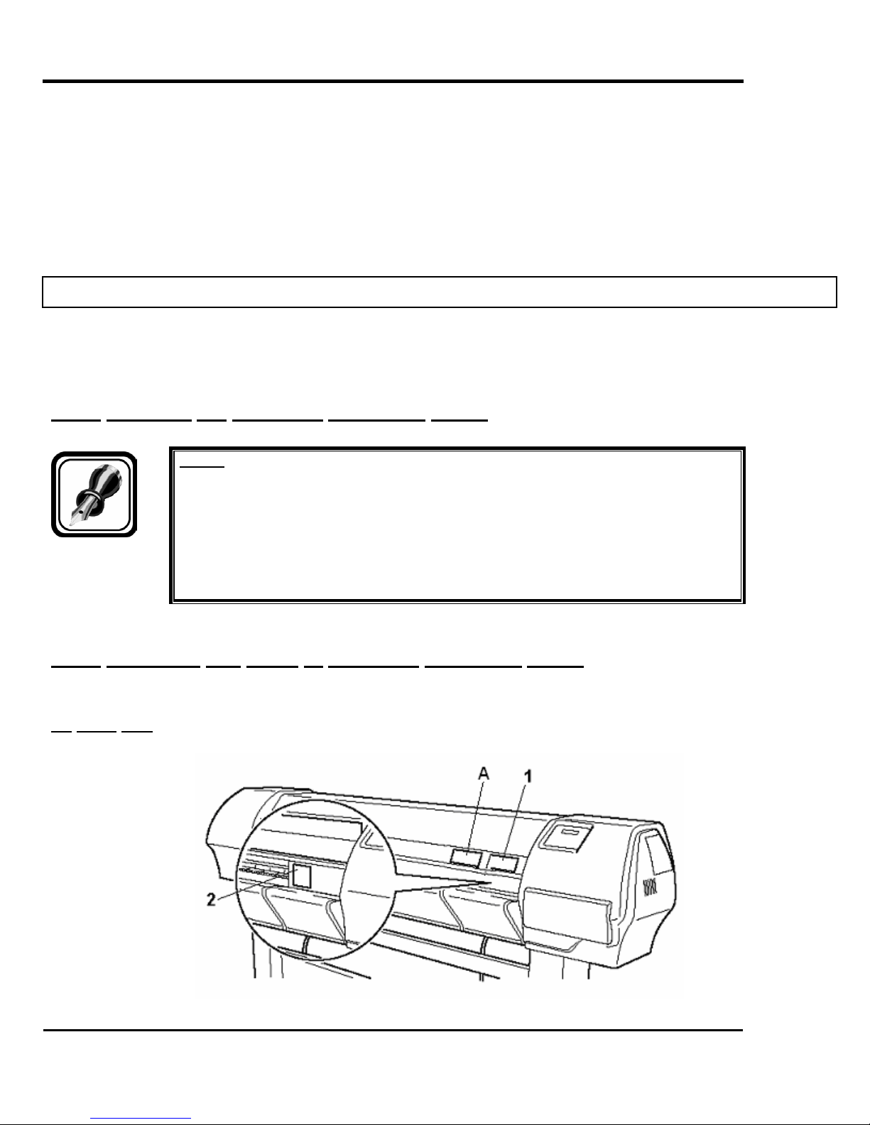
1.4.2. Locations and types of operation procedure labels
The locations of warning labels are shown below.
(1) Front Part
13
AP-74065, Rev. 1.0, 21/11/03
No. Type
1
CAUTION VORSICHT ATTENTION
Falcon II Outdoor series printers – Maintenance Manual
> Do not open the front cover or touch the media during printing.This will result in poor image quality.
> If no printing is to be done for some time, remove the media and put the hold lever in the up
position. Otherwise the media may lift up and become wrinkled and you will not be able to obtain
good printing results.
> Öffnen Sie wärhend des Druckens die Frontabdeckung nicht und berühren Sie das
Druckmaterial nicht.
> Wenn Sie wärhend längere Zeit den Drucker nicht benutzen, nehmen Sie das Druckmaterial
heraus und stellen Sie den Halthebel in die obersten Position. Sonst kann sich das Druckmaterial
aufheben und zerknittern und demzufolge erzielen Sie keine gute Druckergebnisse mehr.
> N'ouvrez pas le couvercle quand l'imprimante est en train d'imprimer. Ne touchez pas non plus
le papier afin d'éviter que la qualité s'aggrave.
> Si vous ne comptez pas imprimer pendant un certain temps, retirez le papier et mettez le levier
en position levée. Sinon, le support risque de se soulever et de se froisser et vous n'obtiendrez
pas de bonne qualité d'impression.
2 Only on a Falcon II Outdoor 2H printer
CAUTION VORSICHT ATTENTION
> To avoid injury, keep fingers away from the
cutter blade.
> Um Verletzungen zu vermeiden, berürhen Sie das
Schneidemesser nicht.
> Ne touchez pas la lame afin d'éviter des blessures.
> To avoid injury, do not touch the edge of the
steel belt.
> Um Verletzungen zu vermeiden, berühren Sie den
Stahl-Antriebsriemen nicht .
> Ne touchez pas la courroie de transmission en
acier afin d'éviter des blessures.
A Only on a Falcon II Outdoor 4H printer
14
AP-74065, Rev. 1.0, 21/11/03
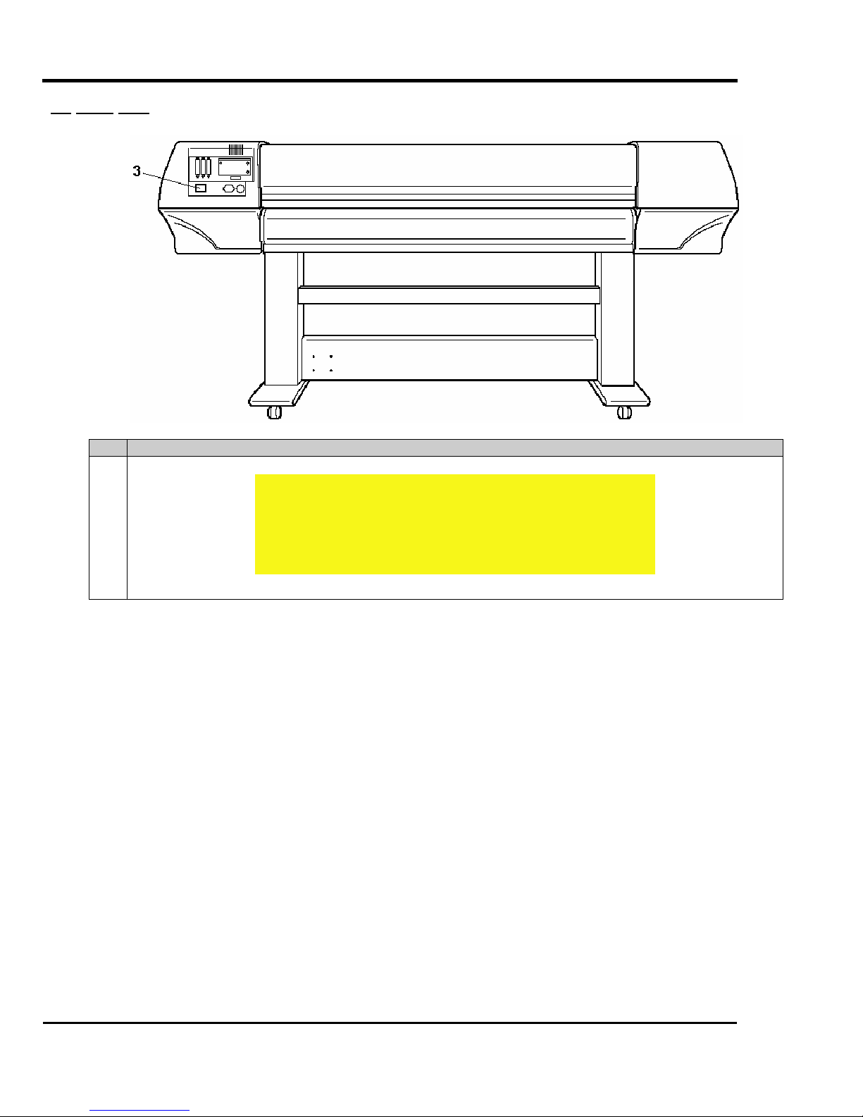
(2) Back Part
Falcon II Outdoor series printers – Maintenance Manual
No. Type
3
CAUTION
THIS UNIT HAS TWO POWER SUPPLY CORDS, WHEN WiNDING
UNIT IS PROVIDED. TO REDUCE THE RISK OF ELECTRICAL
SHOCK, DISCONNECT ALL POWER SUPPLY CORDS
BEFORE SERVICING.
15
AP-74065, Rev. 1.0, 21/11/03
1.5. OPERATION PROCEDURE LABELS
The handling, attachment locations and types of operation procedure labels are explained below.
Your printer has labels, which give simple explanations of operations that require particular care. Read and understand the
locations and contents of these labels thoroughly before performing your work.
Falcon II Outdoor series printers – Maintenance Manual
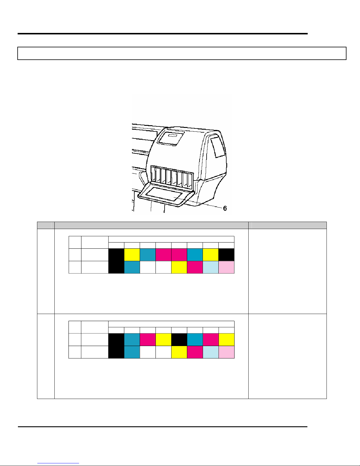
No. Type Refer to
6
Number
of the
Colours
4
6
Ink Type
Eco Solvent
2x4 colours
Eco Solvent
1x6 colours
1
Black
Black
Slot Number of Ink Cartridge
2
3
Cyan
Yellow
Cyan
Transition
Liquid
Magenta
Transition
4
Liquid
56
Yellow
Cyan
Magenta
Magenta
7
Yellow
Light
Cyan
8
Black
Light
Magenta
Æ Refer to the User’s
Guide “Installing ink
cartridges”
Please note that ink
cassettes order is different
for 87” printers versus 50”
and 64” printers.
(Label 50” and 64” printer)
6
Number
of the
Colours
4
6
Ink Type
Eco Solvent
2x4 colours
Eco Solvent
1x6 colours
1
Black
Black
Slot Number of Ink Cartridge
2
3
Magenta
Cyan
Transition
Liquid
Transition
Cyan
4
Yellow
Liquid
56
Black
Cyan
Magenta
Yellow
7
Magenta
Light
Cyan
8
Yellow
Light
Magenta
Æ Refer to the User’s
Guide “Installing ink
cartridges”
Please note that ink
cassettes order is different
for 87” printers versus 50”
and 64” printers.
(Label 87” printer)
16
AP-74065, Rev. 1.0, 21/11/03

Falcon II Outdoor series printers – Maintenance Manual
2. PRODUCT OVERVIEW
2.1. INTRODUCTION
This chapter explains the features, part names, and functions of the printer.
2.2. FEATURES
The features of the printer are explained below.
(1) High speed output
Both models feature new print heads and achieve high speed printing.
They also offer printing widths up to 1263 mm in 50-inch, 1643 mm in 64-inch and 2230 mm in 87-inch spec possible.
(2) Wide variety of compatible media
Adjustable head height can adapt to various media thickness from 0.08 up to 1.1 mm.
(3) Vibrant Colour Reproduction
To reproduce sharp and vivid colour, 4, 6 and 8 ink colours are used for printing. The 220ml large capacity ink
tank is equipped with an IC chip. This unit can automatically detect the ink quantity, significantly improving
productivity.
(4) Effective usage of media
A JOG feature is provided to allow setting of the printing position as required. Because printing can be
performed on media on which was already printed, excess space can be used effectively.
(5) RIP
Software Starter Pack included in-the-box. (To be defined with the order.)
17
AP-74065, Rev. 1.0, 21/11/03
2.3. PART NAMES AND FUNCTIONS
Part names and functions are explained below.
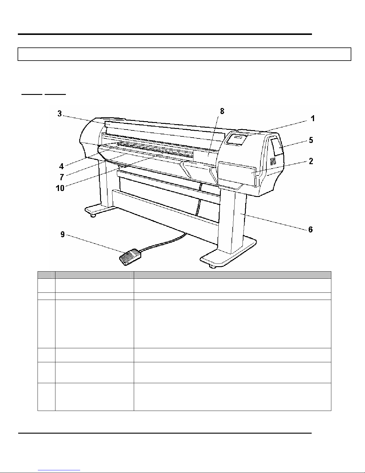
2.3.1. Front
Falcon II Outdoor series printers – Maintenance Manual
No. Name Function
1 Operation panel This panel is used to set operational conditions, the status of the printer,
and other functions.
2 Ink compartment This is the place for installing ink cartridges.
3 Front cover This cover keeps the operator safe from the drive parts of the printer
while it is operating. Only open and/or close the cover to perform
following operations:
¾ Media setting and replacement
¾ Cutter blade replacement
¾ Cleaning the cleaning wiper
¾ In case of media jam.
4 Pressure rollers This roller is used to press the media from above and keep it flat when
printing.
5 Maintenance cover This protects users from electric shocks caused by touching the internal
electrical parts. The cover is opened when expansion memory
(optional) has to be installed, and is closed for normal use.
6 Stand This stand is used to install the printer on a surface flat floor.
The following options are available for installation.
¾ Take-up system + scroller receiver
¾ Motorized roll-off / roll-up system
18
AP-74065, Rev. 1.0, 21/11/03
7 Media cut groove Only onto the Falcon II Outdoor 4H printer !
8 Carriage cover Only onto the Falcon II Outdoor printer !
9 Foot switch This switch is used to raise and lower the pressure rollers.
10 Paper Guide Support the media during printing
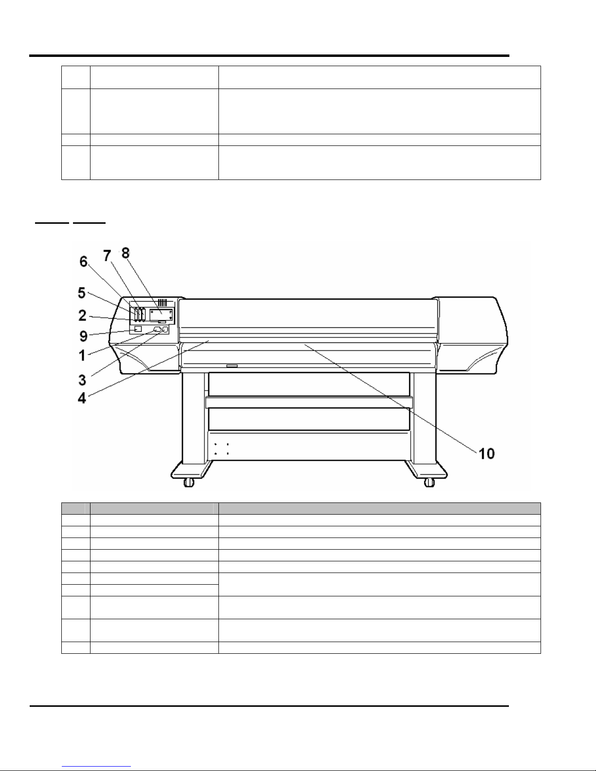
2.3.2. Back
Falcon II Outdoor series printers – Maintenance Manual
Used to cut the media straight when it is cut manually.
This is a cover to protect the user from the internal components of the
unit. This is opened during following operation :
¾ When cleaning the cleaning wiper
In the Falcon II Outdoor it houses post-heater (dryer).
In the Falcon II Outdoor 4H it houses the fixer, post-fixer and dryer.
No. Name Function
1 AC inlet This is the inlet interface to which the power plug is connected.
2 Interface connector This is the connector to which the interface cable is connected.
3 Foot switch connector This is the connector to which the foot switch cable is attached.
4 Insertion slot This is the slot for inserting media when loading it.
5 Interface slot 1 The network interface board attaches here.
6 Interface slot 2
7 Interface slot 3
8 Hard disk slot The hard disk attaches here. When not using a hard disk, keep the
9 Nameplate rating The type, name, serial number, rating and other details of the printer are
10 Rear Heater Supports the media during printing and houses the pre-heaters.
19
This is not used for this printer.
Close it with the cover.
cover closed.
labelled here.
AP-74065, Rev. 1.0, 21/11/03
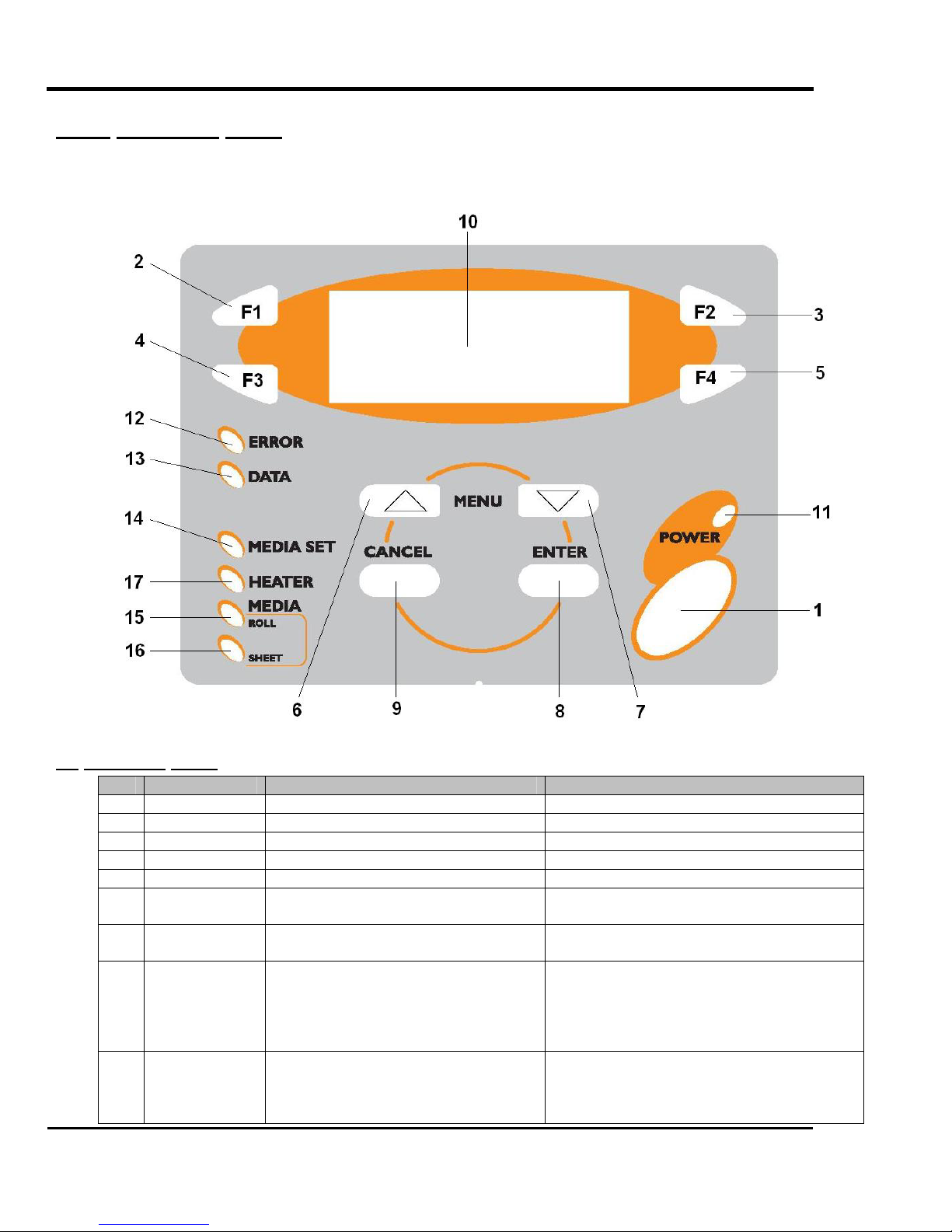
2.3.3. Operation panel
The operation panel is used to set operation conditions, display the status of the printer and set other functions.
The names and functions of the operation keys and status lamps are explained below.
Falcon II Outdoor series printers – Maintenance Manual
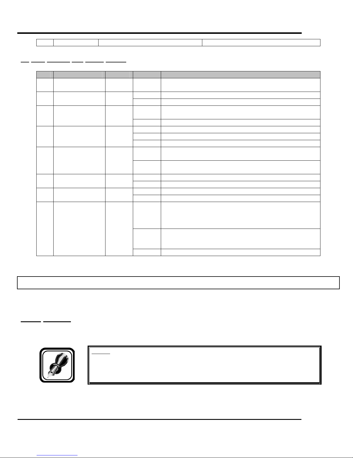
(1) Operation Keys.
No. Name Normal Setup menu display
1 [POWER] key Turns the printer on and off. Turns the printer on and off.
2 [F1] key Executes the function assigned to F1. Executes the function assigned to F1.
3 [F2] key Executes the function assigned to F2. Executes the function assigned to F2.
4 [F3] key Executes the function assigned to F3. Executes the function assigned to F3.
5 [F4] key Executes the function assigned to F4. Executes the function assigned to F4.
6
[MENU ↑] key
7
[MENU ↓] key
8 [ENTER] key Displays the print mode currently set. Determines the new parameter value and
9 [CANCEL] key - Cancels the new parameter value and
20
Changes the LCD monitor display to
setup menu status.
Changes the LCD monitor display to
setup menu status.
Changes the menu in reverse order.
Changes the menu in forward order.
changes the LCD monitor display to the
next menu. Sets the parameter value and
changes the LCD monitor display to the
next menu.
changes the LCD monitor display to the
next menu. Clears the parameter value
and changes the LCD monitor display to
AP-74065, Rev. 1.0, 21/11/03
(2) LCD monitor and status lamps.
No. Name Colour Status Function
10 LCD monitor - - The monitor displays the operation status and error
12 ERROR lamp Red
13 DATA lamp Orange
14 MEDIA SET lamp Orange
17 HEATER lamp Orange
Falcon II Outdoor series printers – Maintenance Manual
the next menu.
messages of the printer.
ON The printer is on. 11 POWER lamp Green
OFF The printer is off.
Flashing An error has occurred. The contents will be displayed on
the LCD monitor.
OFF Either there is no error or the power is off.
ON The printer is receiving print data.
Flashing The printer is analysing receiving data.
OFF The printer is waiting to receive print data.
ON ¾ The pressure rollers are in the release position.
¾ Media is not set.
OFF ¾ The pressure rollers are in secured position.
¾ The media is set.
ON The media type is set to roll media. 15 ROLL lamp Orange
OFF The media type is set to sheet media.
ON The media type is set to sheet media. 16 SHEET lamp Orange
OFF The media type is set to roll media.
ON The temperature of the heating elements is the requested
temperature.
The real temperature is the same as the requested
temperature.
Flashing The heating elements are warming up.
The real temperature is different as the requested
temperature.
OFF The heating elements are powered OFF.
2.4. PRINTER STATUS
The status of the printer is explained below.
2.4.1. Normal
Indicates that the printer can print when media is loaded.
You can also make settings using the operation panel.
Notes :
¾ Refer to the User’s Guide.
21
AP-74065, Rev. 1.0, 21/11/03

Falcon II Outdoor series printers – Maintenance Manual
2.4.2. Setup menu display
Indicates that you can make settings using the operation panel.
Operations for printing can be conducted with the operation panel.
Notes :
¾ Refer to the User’s Guide.
2.4.3. Self-diagnosis Function Display
Indicates that you can make settings concerning adjusting the printer using the operation panel. Keys of the operation
panel have the same names and functions as the display status of the setup menu.
Notes :
¾ Refer to the chapter “Self-Diagnosis function”.
2.4.4. Maintenance Mode Display
Indicates that you can make settings concerning the life of the printer. Keys of the operation panel have the same names
and functions as the display status of the setup menu.
Notes :
¾ Refer to the chapter “Maintenance mode”.
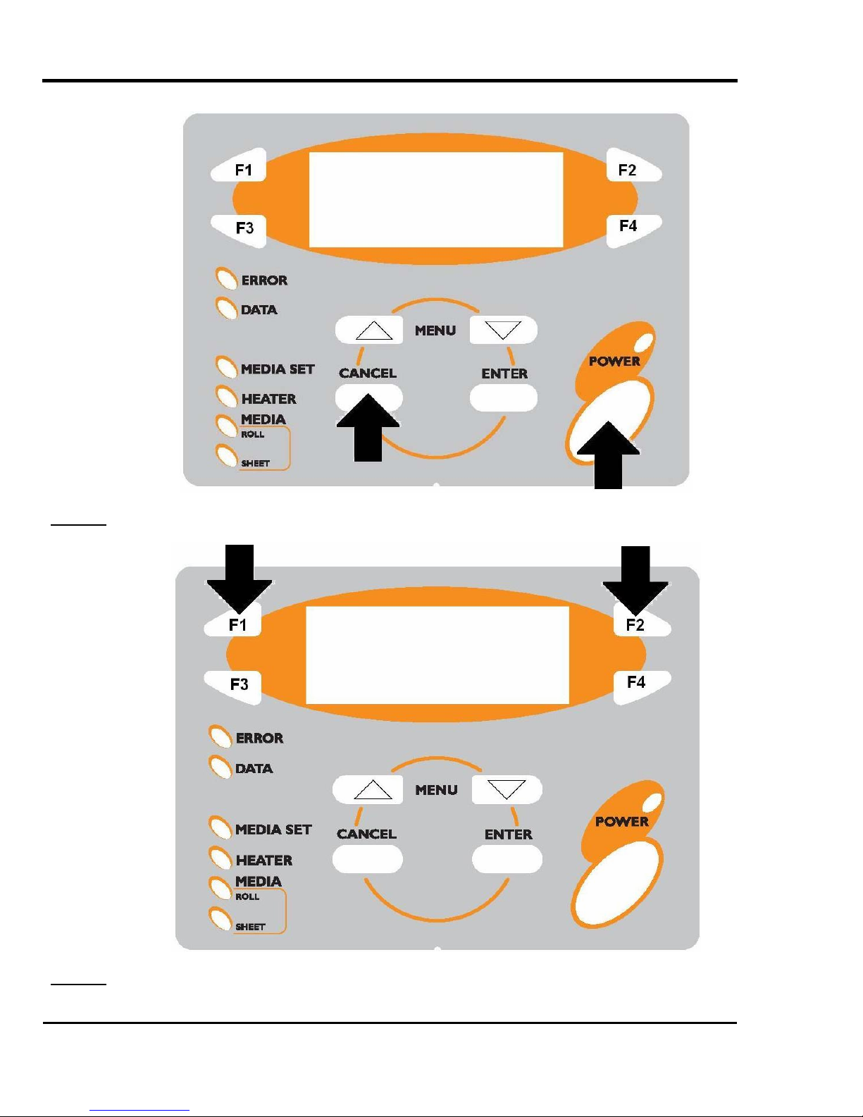
2.4.5. Selecting Language
This chapter explains how to select the language on the display.
Japanese or English is selectable for the display language of the printer.
Follow the steps below to select the display language.
Step 1 : Press the [POWER] key while pressing the [CANCEL] key on the operation panel.
22
AP-74065, Rev. 1.0, 21/11/03
Falcon II Outdoor series printers – Maintenance Manual
Step 2 : Press the [F1] key or [F2] key on the operation panel to change the parameter.
Step 3 : Press the [POWER] key, and then press the [POWER] key again.
23
AP-74065, Rev. 1.0, 21/11/03
Falcon II Outdoor series printers – Maintenance Manual
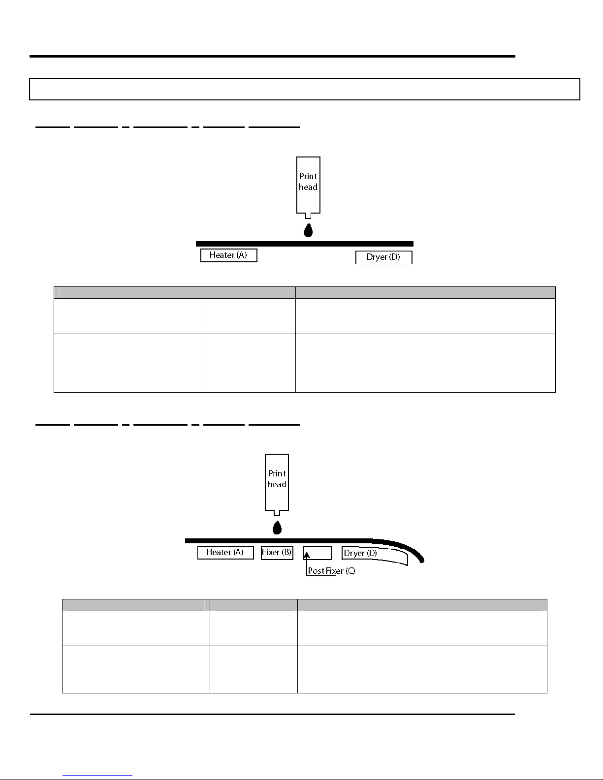
2.5. POSITION AND FUNCTION OF THE HEATING ELEMENTS
2.5.1. Falcon II Outdoor 2 heater printers
Heater element Temperature Function
Pre-heater (Heater A) 20 – 50°C
Dryer (Heater D) 20 – 50°C
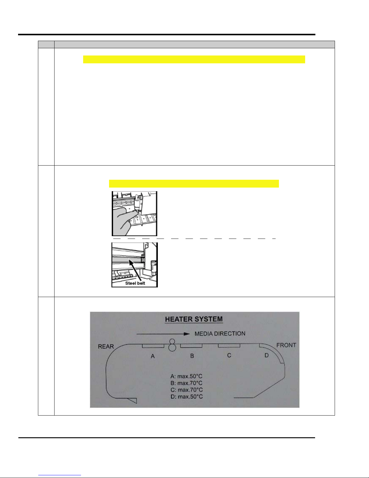
2.5.2. Falcon II Outdoor 4 heater printers
→ Open the pores to make the media more receptive for
eco-solvent or eco-solvent plus™ ink.
→ Applying heating immediately after printing improves
ink/media anchorage.
→ The dryer helps to make the media touch-dry before it
reaches the automatic take-up system.
Heater element Temperature Function
Pre-heater (Heater A) 20 – 50°C
Fixer (Heater B) 20 – 70°C
24
→ Open the pores to make the media more receptive
for eco-solvent or eco-solvent plus™ ink.
→ To establish optimum fixation onto the media
(coated and uncoated).
→ Optimizes the dot gain control.
AP-74065, Rev. 1.0, 21/11/03

Post-Fixer (Heater C) 20 – 70°C
→ The post-fixer finalizes the fixation process and
helps to make the prints touch-dry.
Falcon II Outdoor series printers – Maintenance Manual
Dryer (Heater D) 20 – 50°C
→ The dryer completes the drying for compatibility
with the take-up in combination with higher output
speeds.
→ Stickiness of printed banner materials is improved.
2.5.3. 2 or 4 heater
To verify if your printer is equipped with 2 or 4 heaters, please refer to the photo’s mentioned below.
Falcon II Outdoor 2 heater printer
Falcon II Outdoor 4 heater printer
25
AP-74065, Rev. 1.0, 21/11/03

Falcon II Outdoor series printers – Maintenance Manual
3. SPECIFICATIONS
3.1. INTRODUCTION
This section explains the specifications, optional parts and supplies, installation procedures for optional
parts, and user support for this printer.
3.2. PRODUCT SPECIFICATIONS
Printers 50”- model 64”- model 87”- model
Technology Drop-on-demand Micro Piezo Inkjet Technology.
Variable drop mass output between 5.4 ng and 41.5 ng
Media Thickness Compensation Automatic media thickness compensation.
Variable – RIP controlled – Head Height
Maximum Media Widths 1273 mm 1653 mm 2240 mm
Maximum Print Widths 1263 mm 1643 mm 2230 mm
Media Thickness
Diameter / Core
Weight
Colour Channels 8 colour channels – 4 or 6 process colour output
Inks
Ink Cassette Capacity / Type 220 ml / smart chip ink type & order sensing
Print Modes & Panel Control Options Uni & Bi-directional output, Interweaving, Mirror Output, Multi
Speed Overview Table ( * )
914mm (36”) wide output
Ink Set-Up 2 x 4 Colours 6 Colours 2 x 4 Colours 6 Colours
360 x 360
{{{ {
720 x 360
{
720 x 720
{{{ {
1440 x 720
{
1440 x 1440
{
Output speeds are given for 914 mm (36”) output.
50” output is 7 % faster, 64” output is 12 % faster and 87” output is 18 % faster.
For each mode, the minimum (Super High Quality) and maximum speed (Super Draft) are given.
Mode dependent, there are between 2 and 6 speed levels per mode, accessible via print direction selection
and interweave control from the RIP software.
Top speeds indicated are super draft modes and do not guarantee production output quality on all media
types.
{{{ Variable Drop Compatible { Fixed Drop Compatible
LCD Display Backlight LED – 4 lines x 20 characters
Take-up System (standard) Automated
Roll Media Core 2” & 3”
26
Range: 0.08 mm – 1.1 mm
Maximum: 150 mm / 2” or 3”
Maximum: 50 kg
Eco-Solvent (Plus) 2xCMYK speed set-up
Eco-Solvent (Plus) CMYKLcLm photo tone rendering set-up
Copy, Ink Status, Origin Control
50 & 64 87
5.7 – 37.7 2.9 – 19.6 5.7 – 37.7 3.9 – 27.7
5.8 – 22.8 2.9 – 11.5 5.9 – 23.1 5.3 – 20.6
2.9 – 11.4 1.4 – 5.6 2.9 – 11.5 2.6 – 10.2
2.9 – 5.9 1.4 – 2.8 3.0 – 6.0 2.6 – 5.2
1.4 – 2.9 0.7 – 1.5 1.5 – 3.0 1.3 – 2.6
AP-74065, Rev. 1.0, 21/11/03

Interface Centronics, IEEE 1284 compatible / Network, High Speed
Interface (standard high-speed interface card – 4 Mb/s).
Graphics Command Language RTL-PASS, MH-GL, MH-GL/2
Falcon II Outdoor series printers – Maintenance Manual
Printers 50”- model 64”- model 87”- model
Power Consumption 1100 VA
80 VA in stand-by
mode
External Dimensions in mm (W x D x H)
Weight
2700 x 750 x 1250
170 kg
1300 VA
80 VA in stand-by
mode
3100 x 750 x 1250
195 kg
1400 VA
100 VA in stand-by
mode
3700 x 750 x 1250
215 kg
Noise Level Operating: 54 dB or less
Standard VCCI (Class A), FCC (Class A), UL, CE, CCIB
Standard Items Hard Disk: 20.3 GB – Stores 16 jobs – Up to 99 copies/job –
PostScript RIP included
Optional Item Extra Scroller Bars – Take-up System – Roll-off / roll-up system
Area
Floor loading capability 2490Pa (300kg/m²) or over
Electrical
Environmental
50” model 11.7 m² or larger. Frontage of 4.3 m or greater.
64” model 12.7 m² or larger. Frontage of 4.7 m or greater.
87” model 14.3 m² or larger. Frontage of 5.3 m or greater.
Voltage AC100V - 120V or AC220V – 240V
Frequency 50/60Hz±1Hz
Capacity AC100V - 120V: 3A or more
AC220V - 240V: 1.5A or more
Recommended
working environment
Operational
conditions
Temperature: 25°C
Humidity: 40% to 60%, without condensation
Temperature: 18°C to 35°C
Humidity: 40% to 60%, without condensation
Rate of change Temperature: No more than 2°C per hour
Humidity: No more than 5% per hour
Storage environment Temperature: -20°C to 60°C
Humidity: 5 to 85%, without condensation (When ink has been
discharged.)
Specifications are liable to changes without prior notice. All trademarks mentioned are property of their respective owners.
27
AP-74065, Rev. 1.0, 21/11/03
Falcon II Outdoor series printers – Maintenance Manual
3.3. INTERFACE SPECIFICATIONS
This section explains the specifications for the interfaces supported by this product.
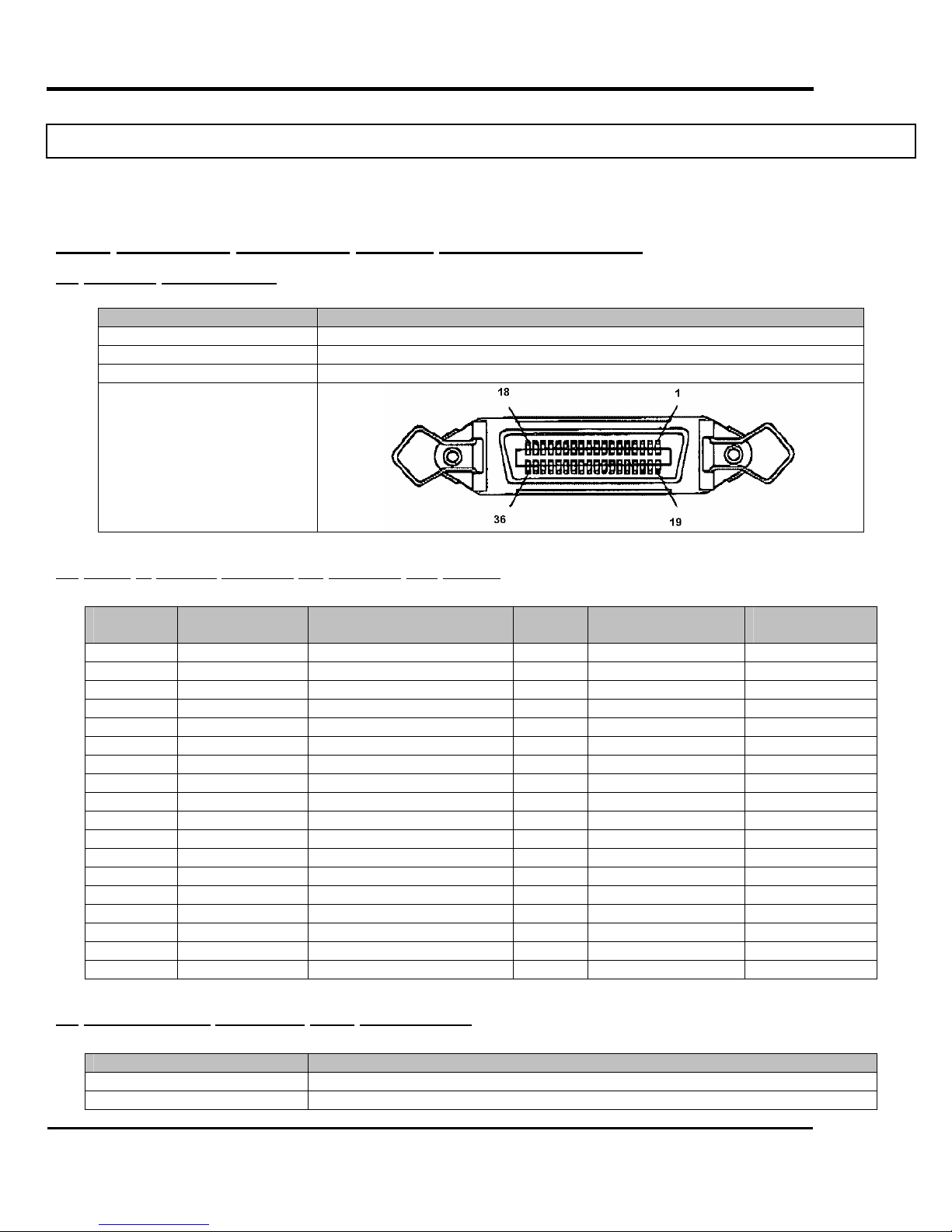
3.3.1. Centronics Bidirection Parallel Interface:IEEE1284)
(1) Interface Specifications
AP-74065, Rev : 1.0, 21/11/2003
Item Specifications
Transmission modes Compatible , Nibble , ECP Mode
Data length 8 bits
Transmission direction Unidirectional (receiving only), Bidirectional
Connector pin number
(2) Table of parallel interface pin numbers and signals
Pin
number
1 STROBE To printer Å 19 SG
2 DATA1 To and from printer Å Æ 20 SG
3 DATA2 To and from printer Å Æ 21 SG
4 DATA3 To and from printer Å Æ 22 SG
5 DATA4 To and from printer Å Æ 23 SG
6 DATA5 To and from printer Å Æ 24 SG
7 DATA6 To and from printer Å Æ 25 SG
8 DATA7 To and from printer Å Æ 26 SG
9 DATA8 To and from printer Å Æ 27 SG
10 ACK From printer Æ 28 SG
11 BUSY From printer Æ 29 SG
12 P ERROR From printer Æ 30 SG
13 SELECTED From printer Æ 31 INIT To printer Å
14 AUTOFD To printer Å 32 FAULT From printer Æ
15 Not connected 33 Not connected
16 SG 34 Not connected
17 FG 35 Not connected
18 +5V 36 SELECTIN To printer Å
Connection
signal
Signal direction Pin
number
Connection signal Signal
direction
(3)
Recommended Centronics cable specifications
Item Specifications
Interface Dual-direction Parallel Interface:IEEE1284
Structure AWG28×18 (twisted pair wiring)
28
AP-74065, Rev. 1.0, 21/11/03

Shield construction Metallic tape + weaving (double shielded cable)
Falcon II Outdoor series printers – Maintenance Manual
Characteristic impedance
62 Ω
3.3.2. Network Interface (Optional) Specifications
Item Specifications
NetWork Type Ethernet IEEE802.3
NetWork I/F 10 Base-T,100 Base-TX
(RJ-45 connector, twisted pair cable)
* Automatic switching
Protocol TCP/IP
Mode
Functions
• ftp
• lpr
• socket
• Automatic protocol recognition
• Transmission speed up to 4 MB/s
• Network environment setting by Web.
29
AP-74065, Rev. 1.0, 21/11/03
Falcon II Outdoor series printers – Maintenance Manual
3.4. INSTALLATION
The Installation of the unit is explained below.
3.4.1. Conditions of the installation environment
Important :
¾ Do not place the printer in following areas. Doing so may result
in the printer falling over and causing injury.
¾ Do not sit on the printer or put heavy things on the printer.
Doing so may cause the printer to fall and injure people.
¾ Do not cover the ventilation hole of the printer with cloth, such
as a blanket or table cloth. Doing so could obstruct ventilation
and cause fire.
¾ Do not place the printer in humid and dusty areas. Doing so may
result in electrical shock or fire.
Unstable surfaces
Slanted place
Where vibration of other machines is transmitted.
(1) Conditions of the installation environment
Select the place to install this unit according to the environmental condition in the table below.
Area
Floor loading capability 2490Pa (300kg/m²) or over
Electrical
Environmental
50” model 11.7 m² or larger. Frontage of 4.3 m or greater.
64” model 12.7 m² or larger. Frontage of 4.7 m or greater.
87” model 14.3 m² or larger. Frontage of 5.3 m or greater.
Voltage AC100V - 120V or AC220V – 240V
Frequency 50/60Hz±1Hz
Capacity AC100V - 120V: 3A or more
AC220V - 240V: 1.5A or more
Recommended
working environment
Operational conditions Temperature: 18°C to 35°C
Rate of change Temperature: No more than 2°C per hour
Storage environment Temperature: -20°C to 60°C
Temperature: 25°C
Humidity: 40% to 60%, without condensation
Humidity: 40% to 60%, without condensation
Humidity: No more than 5% per hour
Humidity: 5 to 85%, without condensation (When ink has been
discharged.)
30
AP-74065, Rev. 1.0, 21/11/03
 Loading...