

Page 1
Mutoh’s Digital
Transfer Printer
DT-Series Printers
Operation Instructions
MUTOH EUROPE N.V. AP-75171, Rev : 1.1, 25/06/2004
Page 2

Mutoh’s DT-Series Printers – Operation Instructions
2
AP-75171, Rev. 1.1, 25/06/04
Page 3

Mutoh’s DT-Series Printers – Operation Instructions
3
AP-75171, Rev. 1.1, 25/06/04
COPYRIGHT NOTICE
COPYRIGHT © 2004 Mutoh Europe N.V. All rights reserved.
This document may not be reproduced by any means, in whole or in part, without written permission of the
copyright owner.
This document is furnished to support the Mutoh’s DT-Series Printers. In consideration of the furnishing of
the information contained in this document, the party to whom it is given, assumes its custody and control
and agrees to the following:
The information herein contained is given in confidence, and any part thereof shall not be copied or
reproduced without written consent of Mutoh Europe N.V.
This document or the contents herein under no circumstances, shall be used in the manufact ure or
reproduction of the article shown and the delivery of this document shall not constitute any right or license to
do so.
June 2004
Published: Mutoh Europe N.V., Archimedesstraat 13, B-8400 Oostende, BELGIUM
Page 4

Mutoh’s DT-Series Printers – Operation Instructions
4
AP-75171, Rev. 1.1, 25/06/04
Page 5

Mutoh’s DT-Series Printers – Operation Instructions
5
AP-75171, Rev. 1.1, 25/06/04
Dear Customer,
As you know, Mutoh Europe’s core business is outdoor printing and signmaking .
A very interesting niche market is digital textile printing. Digital printing can play an important role in the
world of textile printing. Thanks to lots of new developments and the technological possibilities of digital
printing, (such as increasing output speeds, inks offering wider colour gamuts, new ink formulations to
provide durable prints, new coating technologies, etc…,) the gap between traditional machinery (e.g. rotary
screen printers) and drop on demand inkjet narrows considerably.
One application possibility in the field of digital textile printing is heat transfer apparel.
Mutoh’s DT-Series Printers are offered in two different models, i.e. 65” (1653 mm) media width and 90”
(2280 mm) media width.
The Mutoh’s DT-Series Printers are specifically suited to print on transfer paper using water-based dispe rse
dye inks. They incorporates heavy-duty motorized unwinding/winding system for perfect me dia handling and
tracking, 8 drop on demand micro piezo inkjet heads (360 nozzles per colour channel), pre-heater and dryer
and a variable head height from 1.2 mm to 4.0 mm to neutralise media cockling (maximum media thickness
1.1 mm).
This manual provides you all required information to set-up and start the Mutoh machine.
Happy printing !
Mutoh Europe N.V.
Page 6

Mutoh’s DT-Series Printers – Operation Instructions
6
AP-75171, Rev. 1.1, 25/06/04
Page 7

Mutoh’s DT-Series Printers – Operation Instructions
7
AP-75171, Rev. 1.1, 25/06/04
TABLE OF CONTENTS
1. Safety Instructions............................................................................................................................9
1.1. Introduction...............................................................................................................................9
1.2. Warnings, Cautions and Notes..................................................................................................9
1.3. Important safety instructions.....................................................................................................9
1.4. Warning labels ........................................................................................................................12
1.4.1. Handling the warning labels ............................................................................................12
1.4.2. Warning and operation procedure labels on front side....................................................13
1.4.3. Warning labels on rear side..............................................................................................14
1.4.4. Warning labels involving the special shipping liquid......................................................15
1.5 Perfect Media Handling...........................................................................................................16
1.5.1. Measurements to prevent media cockling........................................................................16
1.5.2. Measurements to minimize head touching cockling media.............................................18
2. Installation Procedures...................................................................................................................21
2.1. Installation environment requirements....................................................................................21
2.2. Unpacking...............................................................................................................................23
2.2.1. Unpacking packaging box of the main unit.....................................................................23
2.2.2. Unpacking stand packaging box + KIT ...........................................................................24
2.2.3. Unpacking unwinder / winder 100 box............................................................................25
2.3. Verification of packaged items...............................................................................................26
2.3.1. Packaging box of the main unit .......................................................................................26
2.3.2. Accessories box ...............................................................................................................27
2.3.3. Stand packaging box + KIT.............................................................................................28
2.3.4. Unwinder / Winder 100 Box............................................................................................28
2.4. Part names and functions........................................................................................................29
2.4.1. Front.................................................................................................................................29
2.4.2. Back .................................................................................................................................30
2.4.3. Position and function of the heating elements.................................................................31
2.5. Assembling the unit ................................................................................................................32
2.5.1. Assembling the stand.......................................................................................................32
2.5.2. Installing the stand...........................................................................................................33
2.5.3. Fixing the printer body onto the stand.............................................................................34
2.5.4. Removal of protective packaging material ......................................................................35
2.5.5. Installing the printer.........................................................................................................37
2.6. Installing Unwinder / winder 100 and waste bottle ................................................................38
3. Preparing for a job .........................................................................................................................39
3.1. Introduction.............................................................................................................................39
3.2. Connecting the power cable....................................................................................................39
3.3. Connecting the foot switch .....................................................................................................42
3.4. Connecting the printer to your PC ..........................................................................................44
3.4.1. System requirements........................................................................................................44
3.4.2. Selecting cables................................................................................................................44
3.4.3. Connecting the Centronics interface................................................................................44
3.4.4. Connecting the network interface....................................................................................45
3.5. Turning the power ON/OFF....................................................................................................47
3.5.1. Turning the power ON.....................................................................................................47
3.5.2. Turning the power OFF....................................................................................................48
3.6. Installing ink cassettes ............................................................................................................50
3.7. Media handling .......................................................................................................................53
Page 8

Mutoh’s DT-Series Printers – Operation Instructions
8
AP-75171, Rev. 1.1, 25/06/04
3.7.1. Loading roll media...........................................................................................................53
3.7.2. Setting media type............................................................................................................57
3.8. Media retainers (media holder)...............................................................................................59
3.9. Using the ETT system.............................................................................................................62
3.10. Pressure rollers disabler tool.................................................................................................65
3.11. Controlling the heater elements ............................................................................................68
4. Daily Maintenance.........................................................................................................................71
4.1. Replacing ink cassettes ...........................................................................................................71
4.2. Replacing the cutting blade.....................................................................................................74
4.3. Replacing the waste liquid tank..............................................................................................79
4.4. Cleaning..................................................................................................................................81
4.4.1. Cleaning the outer case....................................................................................................81
4.4.2. Cleaning the inside of the printer.....................................................................................82
4.4.3. Head cleaning...................................................................................................................83
4.4.4. Cleaning the cleaning wiper.............................................................................................85
5. Understanding the Operation Panel & Printer Controls.................................................................87
5.1. Operation panel.......................................................................................................................87
5.2. Printer status............................................................................................................................89
5.2.1. Normal .............................................................................................................................89
5.2.2. Setting menu display........................................................................................................89
5.2.3. Changing the printer status ..............................................................................................90
5.2.4. Details of the setup items.................................................................................................91
Page 9
Mutoh’s DT-Series Printers – Operation Instructions
9
AP-75171, Rev. 1.1, 25/06/04
1. SAFETY INSTRUCTIONS
1.1. INTRODUCTION
This chapter explains the meaning of safety terms for personnel who operate this equipment, important
safety instructions and the positions of the warning labels.
Important :
• Be sure to follow all instructions and warnings on this manual when using
the equipment.
1.2. WARNINGS, CAUTIONS AND NOTES
Safety terms in this manual and the contents of warning labels attached to the printer are categorized into
the following three types depending on the degree of risk (or the scale of accident ).
Read the following explanations carefully and follow the instructions in this manual.
Safety terms Details
Important Must be followed carefully to avoid death or serious bodily injury
Caution Must be observed to avoid bodily injury (moderately or lightly) or damage to your
equipment
Notes Contains important information and useful tips on the operation of your printer
1.3. IMPORTANT SAFETY INSTRUCTIONS
General safety instructions that must be observed to use the equipment safely are explained below.
¾ Do not place the printer in the following areas. Doing so may result in the printer tipping or falling
over and causing injury.
• Unstable surfaces
• Angled place
• Areas subject to vibration by other equipment
¾ Do not stand on or place heavy objects on your printer. Doing so may result in the printer tipping
or falling over and causing injury.
¾ Do not cover the ventilation hole of your printer with cloth, such as a blanket or table cloth. Doing
so could obstruct ventilation and cause fire.
¾ Do not place the printer in humid and dusty areas. Doing so may result in electrical shock or fire.
¾ Do not use a damaged power cable. Doing so may result in electrical shock.
¾ Do not attempt to plug in electrical plugs with wet hands. Doing so may result in electrical shock.
Page 10

Mutoh’s DT-Series Printers – Operation Instructions
10
AP-75171, Rev. 1.1, 25/06/04
¾ Do not connect earth cables in the following areas.
• Gas pipes → Doing so may cause fire or an explosion.
• Earth terminals for telephone line or lightening rod → Doing so may cause a large flow of
voltage if lightening occurs.
• Water pipes or faucets → If there is a plastic part in the pipe, the earth will not work
properly.
¾ Do not insert or drop metal or inflammable objects into openings, such as ventilation outlets.
Doing so may result in electrical shock and fire.
¾ Stop using your printer if a liquid is spilled into it. This may cause electrical shock or fire. Turn the
printer off as soon as possible, unplug the power cord, contact your local MUTOH dealer.
¾ Be sure to use the attached cable. Otherwise, electrical shock or fire may occur.
¾ Be sure to use the specified voltage (AC 100 V to 120V, or AC 220V to 240V). Otherwise,
electrical shock or fire may occur.
¾ Use electricity directly from a power outlet (AC 100 V to 120V, or AC 220V to 240V). Do not put
many loads on one electrical output. Otherwise, heat may be generated and cause fire.
¾ Be sure to use an outlet with an earth terminal and use the terminal correctly. Otherwise,
electrical shock or fire may occur.
¾ Follow the instructions below when handling the power cable.
o Do not modify the cable.
o Do not put heavy objects on the cable.
o Do not bend, twist or pull the cable.
o Do not wire the cable near equipment that generates heat.
¾ Follow the instructions below when handling the power plug. Otherwise, fire may occur.
o Wipe away dust and any other residue before inserting the plug.
o Ensure that the plug is firmly inserted as far as it will go.
¾ When handling the foot switch, be aware of the following:
o Do not place anything heavy on the foot switch.
o Do not bend the cable of the foot switch with force and do not pull.
o Do not place the foot switch near thermal devices.
¾ When handling ink cassettes, be careful that ink does not get in your eyes or on your skin.
However, if this happens, flush immediately with water. Otherwise, your eyes may become
congested or inflamed slightly. If you feel discomfort, consult a doctor immediately.
¾ Do not disassemble ink cassettes. Otherwise, ink may get in your eyes or on your skin.
¾ Be careful not to pinch your fingers when opening and closing the cover of the ink compartment.
¾ Be careful not to pinch your fingers when opening and closing the front cover.
¾ Follow the instructions below when connecting the network interface cable. Otherwise, electrical
shock or fire may occur.
o Do not touch the connector.
o Do not connect the network cable connector that is not the same specification to the
interface board.
Page 11

Mutoh’s DT-Series Printers – Operation Instructions
11
AP-75171, Rev. 1.1, 25/06/04
¾ When cutting the roll media, be careful of the following. Incorrect handling can result in injury to
the hands and fingers from the razor blade.
o When holding the media, do not place fingers over the media cut groove.
o Move the razor blade slowly along the media cutting groove.
¾ Do not use thinner, benzene, alcohol or other active agents. Doing so may result in damage or
paint peeling from the casing.
¾ Be careful not to spill water inside the printer. Doing so may result in a short circuit.
¾ Be careful not to touch the heaters during or after operation. Doing so may result in burns.
¾ Never open the covers fixed with screws. Doing so may result in electrical shock or a
malfunctioning in the printer.
¾ Do not touch the cutter blade. Doing so may result in bodily injury.
¾ Do not cut hard objects or drop the cutter. Doing so may damage or chip the cutter blade.
¾ Do not bend or pull the waste fluid tube. Doing so may cause that the waste fluid will leak out and
malfunction in the product.
¾ Do not touch the cleaning wiper or the head cap unit while cleaning the cleaning wiper. Doin g so
may result in poor head cleaning because of oil on your hands.
¾ Do not tilt the printer, stand it against a wall or turn it upside down. Doing so may cause ink to
leak inside the printer. Movement after transport is also not covered by the warranty.
¾ When installing options, do not touch the elements on the circuit board. The elements on the
boards can be very hot and can cause burns.
¾ Have four or more people unpack and assemble the printer.
¾ When lifting the printer out of the packing box, be sure to remove the vinyl cover first, then grab
the holding grips on the sides of the printer. Lifting the printer with the vinyl cover on may cause
your hands to slip and drop or damage the printer.
¾ Have two or more people transport the printer.
¾ Ensure that the plug has been disconnected from the power socket when it is not to be used for a
long time.
¾ Earth wires must be connected to wires or terminals that fulfill the conditions below.
o Earth terminals of power sockets
o Earth wires with copper morsel that is at least 650 mm under the ground
¾ Earth wires must be connected to wires or terminals that fulfill the conditions below.
¾ Keep the printer horizontal during transportation.
Page 12
Mutoh’s DT-Series Printers – Operation Instructions
12
AP-75171, Rev. 1.1, 25/06/04
¾ Be sure to do the following before attaching options.
o Turn the printer off.
o Unplug the power cord from the socket.
o Unplug cables connected to the printer. Otherwise, damage to the printer or your computer
may occur.
o Remove electrostatic charge from your clothes and body by touching the metal parts of the
printer.
o Electronic components such as the memory may malfunction if exposed to an electrostatic
charge.
¾ The unit is delivered / shipped with special shipping liquid. This to prevent air coming into the ink
supply system. Make sure that air never comes into the ink supply system.
1.4. WARNING LABELS
The handling, attachment locations, and types of warning labels are explained below.
Warning labels are attached on areas which require attention. Read and understand the po sitions and
contents thoroughly before performing your work.
1.4.1. Handling the warning labels
Be sure to note the following when handling the labels.
Notes :
• Make sure that all labels can be recognized. If text or illustrations cannot be seen
clearly, either clean or replace the label.
• When cleaning labels, use a cloth with water or neutral detergent. Do not use a
solvent or gasoline.
• If a warning label is damaged, lost or cannot be recognized, replace the label.
When replacing warning labels, contact your local MUTOH dealer.
Page 13
Mutoh’s DT-Series Printers – Operation Instructions
13
AP-75171, Rev. 1.1, 25/06/04
1.4.2. Warning and operation procedure labels on front side.
No. Type
1
2
Page 14
Mutoh’s DT-Series Printers – Operation Instructions
14
AP-75171, Rev. 1.1, 25/06/04
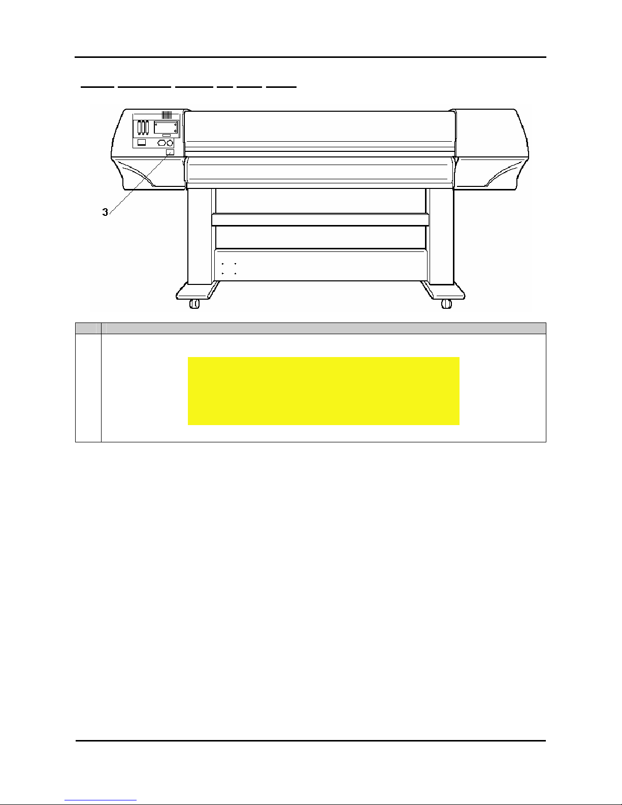
1.4.3. Warning labels on rear side.
No. Type
3
CAUTION
THIS UNIT HAS TWO POWER SUPPLY CORDS, WHEN WiNDING
UNIT IS PROVIDED. TO REDUCE THE RISK OF ELECTRICAL
SHOCK, DISCONNECT ALL POWER SUPPLY CORDS
BEFORE SERVICING.
Page 15

Mutoh’s DT-Series Printers – Operation Instructions
15
AP-75171, Rev. 1.1, 25/06/04
1.4.4. Warning labels involving the special shipping liquid.
Nr. Description
1
BEFORE powering on printer,
REMOVE clamp from waste tubes:
On right bottom side of machine!
Remove dummy cassettes before powering on the printer.
2
BEFORE powering on printer;
REMOVE clamps from waste tubes
3
You can also find a label on each of the 8 dummy cassettes:
Dummy cassette, please remove before powering on the printer.
4
BEFORE powering on printer,
REMOVE dummy cassettes.
5
Plastic bag with the 8 waste tubes and clamps
Page 16

Mutoh’s DT-Series Printers – Operation Instructions
16
AP-75171, Rev. 1.1, 25/06/04
1.5 PERFECT MEDIA HANDLING
The DT-series printer prints on transfer paper with water-based disperse dye inks. An annoying effect of
transfer paper when coming into contact with ink is expansion of the media.
Notes :
The transfer papers with a low g/m², the thinnest, are most sensitive to expanding. This
expansion results in media coming up from the print platform between the different
pressure rollers.
Therefore, the DT-series printer has been specially developed to avoid the media cockling to occur and to
minimize the print heads to touch the media when minimal media cockling occurs.
1.5.1. Measurements to prevent media cockling
Media cockling is prevented to avoid the print heads to touch the media (protect heads and print result) and
to avoid the cockling structure to become apparent in the print result.
1.5.1.1. Unwinder / winder 100
The unwinder / winder 100 system always provides an equal tension on the media when printing.
It is important that the unwinder / winder 100 is perfectly lined out to prevent cockling. To line out the
unwinder / winder 100, please refer to the user’s guide “Handling Roll Media”.
Caution :
• Before installation and alignment of the unwinder / winder 100, please make sure
the printer is placed level!
1.5.1.2. Print environment of transfer paper
Environmental Recommended
working environment
Temperature: 19℃ - 26℃
Humidity: 30% to 60%, without condensation
Notes :
Please note that some inks require a humidity of more than 50%, other inks can be used
at 30% humidity. Please contact your ink supplier for optimum printing conditions.
Page 17
Mutoh’s DT-Series Printers – Operation Instructions
17
AP-75171, Rev. 1.1, 25/06/04
Caution :
• The size of the recommended media can change at a fixed ratio according to the
temperature changes of the working environment. Before using media, place the
media roll in the working environment for at least 24 hours, to have it match to the
temperature of the working area.
• Printing before the media could accommodate to the printing environment may
cause media jams due to slippage or creases. This also adversely effects the
quality of printing.
1.5.1.3. Pre-heating of the transfer paper
The DT-series printer is equipped with a pre-heater. (Range up to 50°C.)
Caution :
• We recommend you to set the pre-heater temperature at 50°C. This to be sure that
transfer paper is already expanded a little before reaching the pressure rollers.
1.5.1.4. Extra fans
The DT-series printer is equipped with extra fans to keep the transfer paper flat on the print platform.
Caution :
• We recommend you to select “HIGH” in the vacuum menu. Only use “Low” or
“Medium” when using sheet media.
1.5.1.5. Pressure rollers disabler tool
The pressure roller disabler tool allows a pressure roller to be lifted while printing, thus providing the
necessary space for media to expand.
Caution :
• When using roll media, we recommend you to use two pressure rollers disabler
tools on both side of the media, as well as two on 1/3 and two on 2/3 of the media.
• It is not necessary to use pressure rollers disabler tools when using sheet media.
Page 18
Mutoh’s DT-Series Printers – Operation Instructions
18
AP-75171, Rev. 1.1, 25/06/04
1.5.1.6. Media Retainers (holders)
The media cockling causes the transfer paper edges to curl. Media retainers keep the media edges pushed
down.
Caution :
• When using roll media, we recommend you to always use the media retainers.
Caution :
• When using the media retainers, do not use the cut function.
Notes :
• When using sheet media, media retainers are not necessary used. If used, please
make sure the media is loaded correctly straight. Otherwise, media can slant and
the media retainers could tear the transfer paper.
1.5.2. Measurements to minimize head touching cockling media
In case of media cockling following tools are available to avoid the print heads to touch the media (protect
heads and print result).
1.5.2.1. ETT (patent pending)
The ETT Extra Tension Tool pulls the media in line with the print platform. The tension on the sides is
always bigger than in the middle. As a result possible curls are straightened.
Notes :
• Always make sure that the edges of the media are supported by the edges of the
ETT.
• Only use the middle part of the ETT if media with is larger than 51”.
Page 19
Mutoh’s DT-Series Printers – Operation Instructions
19
AP-75171, Rev. 1.1, 25/06/04
1.5.2.2. Head Height
The DT-series printer can be set at the following head heights : 1.2 mm (LOW), 2.2 mm (MIDDLE) and 4 mm
(HIGH).
Caution :
• We recommend you to use the lowest possible head height. This to obtain the best
printing quality.
Caution :
• At all head heights, be sure that the correct media thickness is set!
Page 20

Mutoh’s DT-Series Printers – Operation Instructions
20
AP-75171, Rev. 1.1, 25/06/04
Page 21
Mutoh’s DT-Series Printers – Operation Instructions
21
AP-75171, Rev. 1.1, 25/06/04
2. INSTALLATION PROCEDURES
2.1. INSTALLATION ENVIRONMENT REQUIREMENTS
Install the unit on a proper location referring to the following.
Important :
• Do not place the printer on a location under the following conditions. Doing
so may cause the product to fall, become damaged, or cause injury.
o Unstable surfaces
o Slanted surfaces
o Locations that are subject to vibration from other product
• Do not stand on the printer or place any heavy objects on it. Doing so may
cause it to fall over, become damaged, or cause injury.
• Do not cover the ventilation hole of the printer with cloth, such as a blanket
or table cloth. Doing so could prevent the printer from ventilating and cause
fire.
• Keep the printer away from humid and dusty areas. Humidity may result in
electrical shock or fire.
Choose a place for printer installation following the requirements in the table below.
65” model 12.7m² (144ft²) or larger. Frontage of 4.7m (15.7ft) or greater.
Area
90” model 14.3m² (162ft²) or larger. Frontage of 5.3m (17.7ft) or greater.
Floor loading capability 2490Pa (300kg/m²) or over
Voltage AC100V - 120V or AC220V – 240V
Frequency
50/60Hz±1Hz
Electrical
Capacity AC100V - 120V: 12A or more
AC220V - 240V: 6A or more
Recommended
working environment
Temperature: 25℃
Humidity: 30% to 60%, without condensation
Operational conditions
Temperature: 19℃ to 26℃
Humidity: 30% to 60%, without condensation
Rate of change
Temperature: No more than 2℃per hour
Humidity: No more than 5% per hour
Environmental
Storage environment
Temperature: -20℃ to 60℃
Humidity: 5% to 85%, without condensation (When ink has
been discharged.)
Page 22
Mutoh’s DT-Series Printers – Operation Instructions
22
AP-75171, Rev. 1.1, 25/06/04
Notes :
• Avoid the following temperature and humidity conditions. Otherwise, printed
images may appear differently from what you expect:
o Places where sudden changes in temperature and humidity are expected,
even though the condition is within the range written above.
o Places where direct sunlight or excessive lighting are expected.
o Places where air conditioners blow directly.
• MUTOH recommends that the printer should be installed where air conditioning can
be adjusted easily.
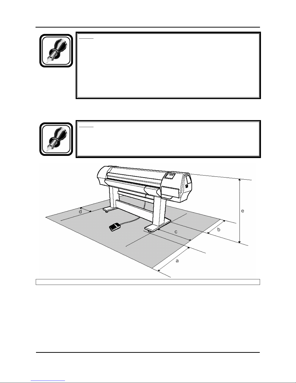
Install the product on a flat surface that fulfills the following conditions.
Notes :
• Refer to “Product Specifications” of the User's Guide for the information of the
product.
a=1000mm b=1000mm c=1500mm d=600mm e=1250mm
Page 23
Mutoh’s DT-Series Printers – Operation Instructions
23
AP-75171, Rev. 1.1, 25/06/04
2.2. UNPACKING
The unpacking procedure is described below.
The product is sent to the user in 3 boxes, 1 for the main unit, a second for the stand and one for the
unwinder / winder 100 system.
Caution :
• When unpacking this product, always work with at least 4 people.
• When removing this product from the packaging box, always remove the vinyl
plastic, and hold on the side of the product. Holding the unit over the vinyl plastic
wrapping can result in slippage and dropping the unit, resulting in damage.
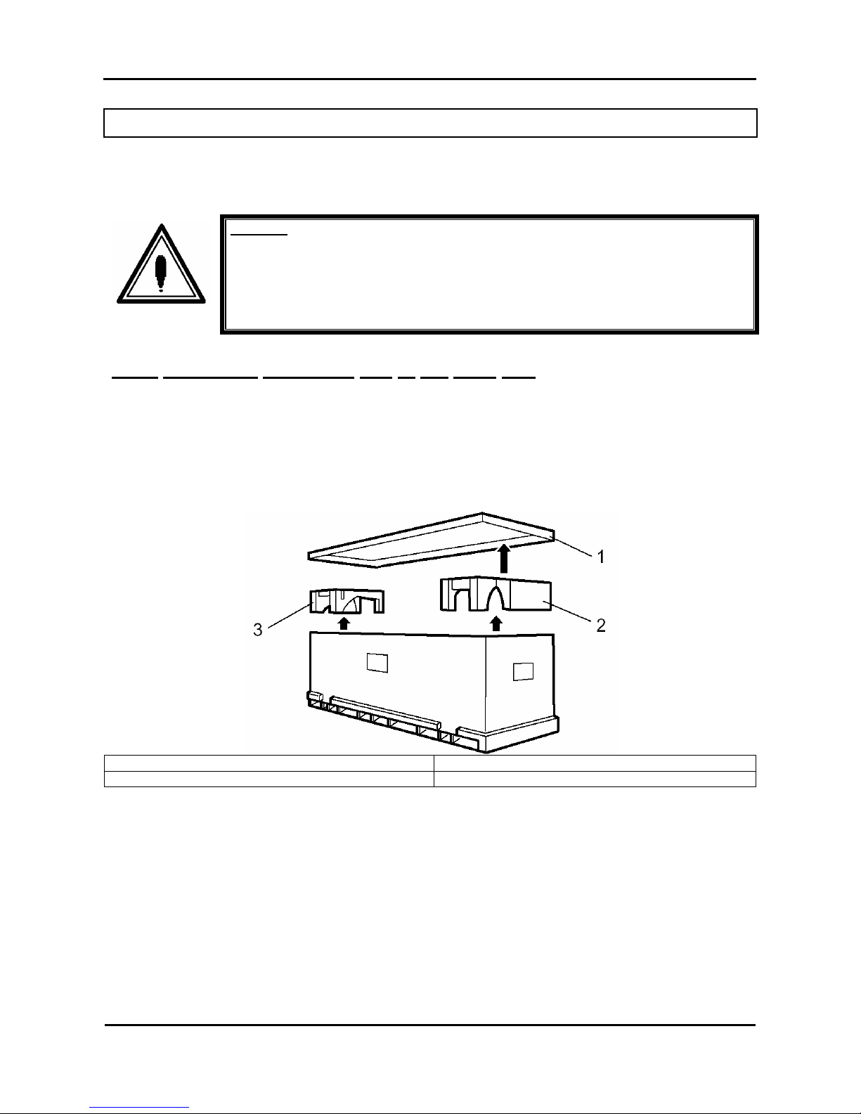
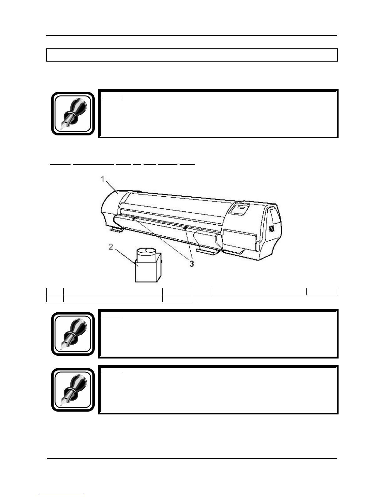
2.2.1. Unpacking packaging box of the main unit
Unpack the package of the main unit according to the following procedure.
Step 1 : Move the packaging of the main unit to the location to unpack.
Step 2 : Remove the restraining bands.
Step 3 : Remove the top board and take out the packaging material (right upper side and left upper side).
1. Top board 2. Packaging material (right upper side)
3. Packaging material (left upper side)
Page 24
Mutoh’s DT-Series Printers – Operation Instructions
24
AP-75171, Rev. 1.1, 25/06/04
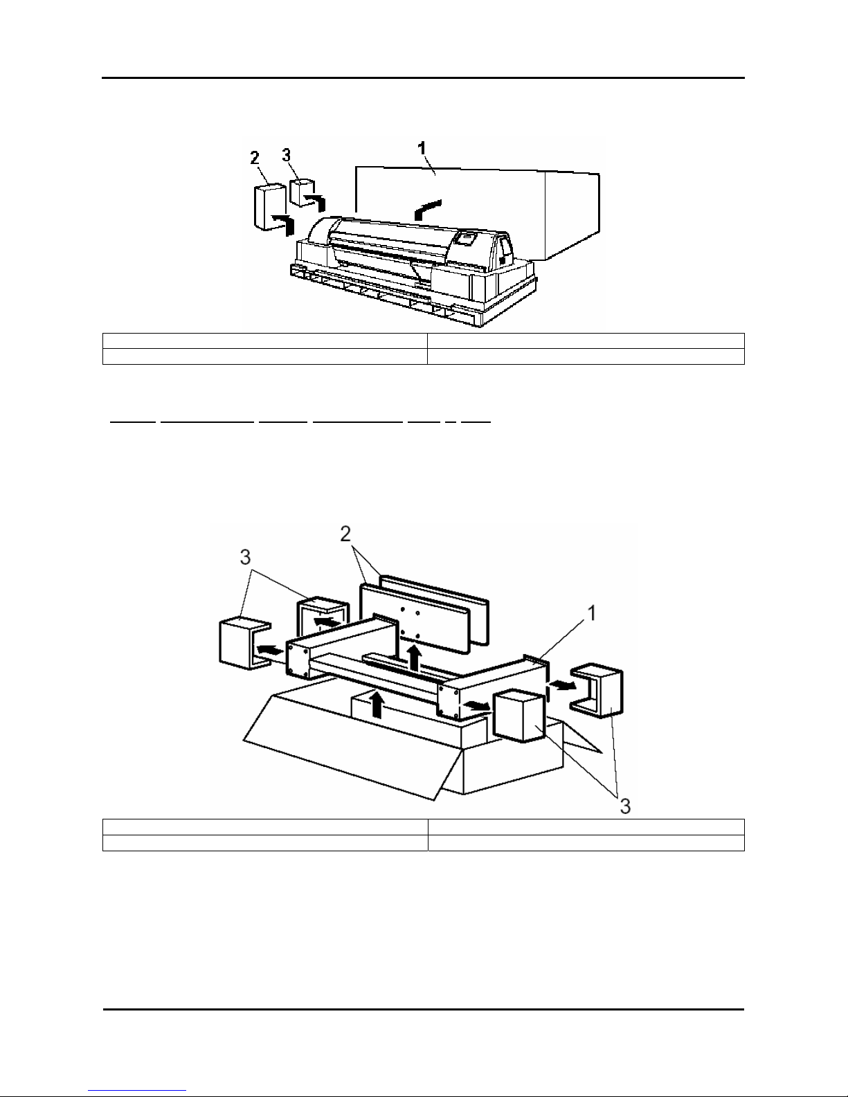
Step 4 : Remove the outer boards and take out the accessory box and the packaging box of the waste
fluid tank.
1. Outer board 2. Accessory box
3. Packaging box of the waste fluid tank
2.2.2. Unpacking stand packaging box + KIT
Unpack the package of the stand according to the following procedure.
Step 1 : Move the packaging of the stand to the location to unpack.
Step 2 : Open the package and take out the foot, stay and the four packaging materials.
1. Stay 2. Foot
3. Packaging material 4 = KIT
Page 25
Mutoh’s DT-Series Printers – Operation Instructions
25
AP-75171, Rev. 1.1, 25/06/04
2.2.3. Unpacking unwinder / winder 100 box
Notes :
For further information about the unwinder / winder 100, please refer to the user’s guide
“Handling roll media”.
Page 26
Mutoh’s DT-Series Printers – Operation Instructions
26
AP-75171, Rev. 1.1, 25/06/04
2.3. VERIFICATION OF PACKAGED ITEMS
After unpacking the packaging box, inspect if the unit is not damaged and that all necessary parts are
present.
Notes :
• If any part is missing or broken, contact either of the following:
o The shop where you bought your MUTOH printer.
o Your local MUTOH dealer.
2.3.1. Packaging box of the main unit
1 Main unit 1 set 3 Media retainers 2
2 Waste fluid tank 1 set
Notes :
The unit is delivered / shipped with special shipping liquid. This to prevent air coming
into the ink supply system. Make sure that air never comes into the ink supply system.
Notes :
The two media retainers are taped (in bag) onto the print platform.
Page 27
Mutoh’s DT-Series Printers – Operation Instructions
27
AP-75171, Rev. 1.1, 25/06/04
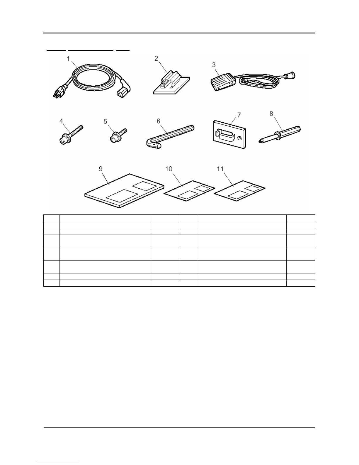
2.3.2. Accessories box
1 Power cable 1 9 User's Guide 1
2 Tube clamp 2 10 Quick Start Manual 1
3 Foot switch 1 11 Installation sheets
4 Hexagon socket head cap screw
(M6 x 30)
8
5 Hexagon socket head cap screw
(M6 x 16)
8
6 Assembly tool (Hexagon wrench:
diagonal diameter 5mm)
1
7 Cable clamp 3
8 Screw driver 1
Page 28
Mutoh’s DT-Series Printers – Operation Instructions
28
AP-75171, Rev. 1.1, 25/06/04
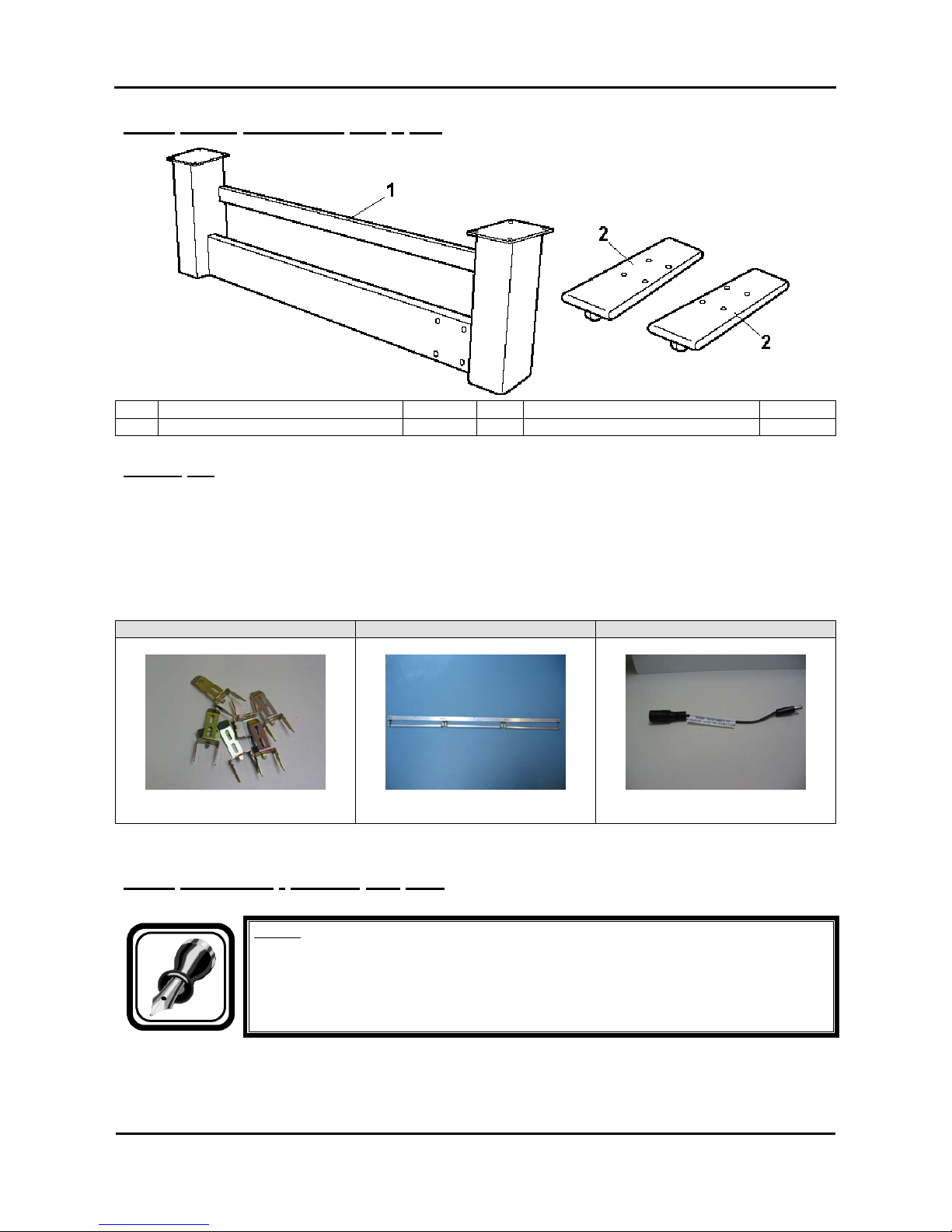
2.3.3. Stand packaging box + KIT
1 Stand 1 set 2 Foot 2
3 KIT 1
3.2.3.1. KIT
The DT-series printer has some unique items delivered with the printer. These items are all special
measurements to prevent media cockling and / or head strikes.
→ 10 x Pressure roller disabler tool
→ 1 x Extra tensioning Tool (3 pieces)
→ 1 x wire to turn the winding side of the winder 100
Pressure roller disabler tool Extra tensioning Tool wire to turn the winding side
2.3.4. Unwinder / Winder 100 Box
Notes :
For further information about the unwinder / winder 100, please refer to the user’s guide
“Handling roll media”.
Page 29
Mutoh’s DT-Series Printers – Operation Instructions
29
AP-75171, Rev. 1.1, 25/06/04
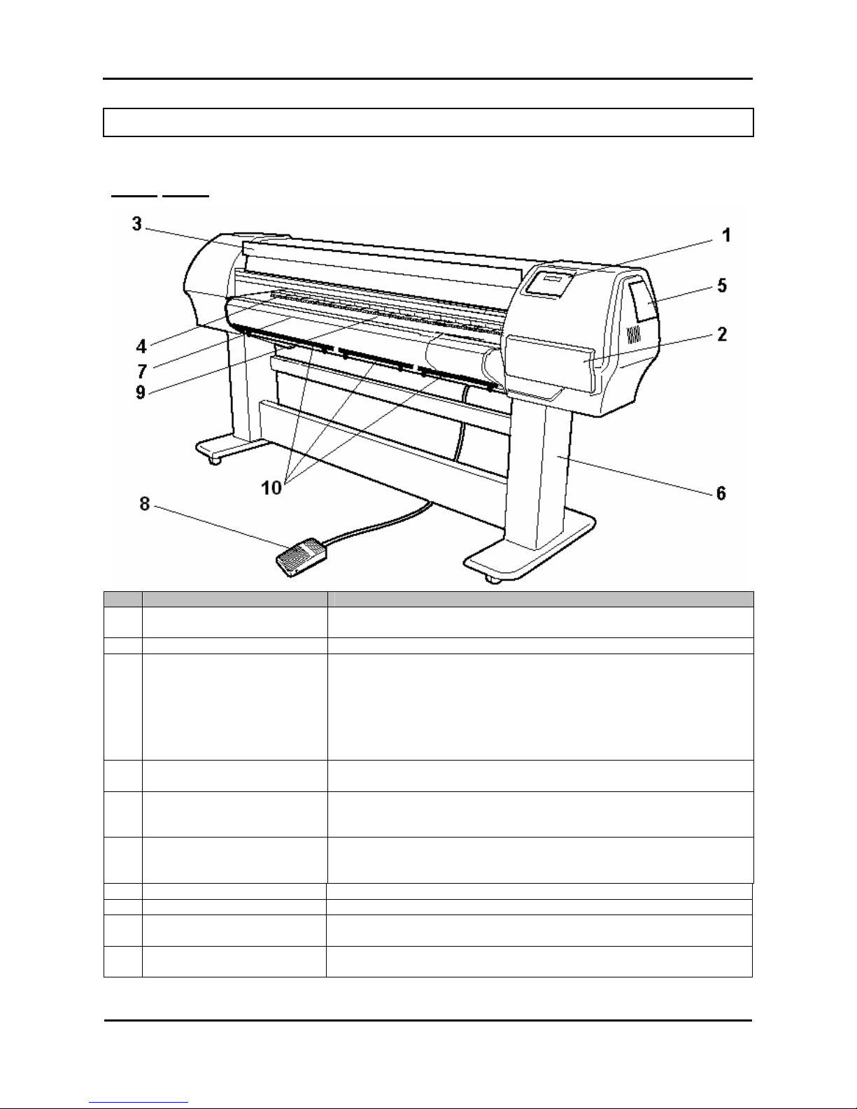
2.4. PART NAMES AND FUNCTIONS
Part names and functions are explained below.
2.4.1. Front
No. Name Function
1 Operation panel This panel is used to set operational conditions, the status of the
printer, and other functions.
2 Ink compartment This is the place for installing ink cassettes.
3 Front cover This cover keeps the operator safe from the drive parts of the printer
while it is operating. Only open and/or close the cover to perform
following operations:
¾ Media setting and replacement
¾ Cutter blade replacement
¾ Cleaning the cleaning wiper
¾ In case of media jam.
4 Pressure rollers This roller is used to press the media from above and keep it flat when
printing.
5 Maintenance cover This protects users from electric shocks caused by touching the
internal electrical parts. The cover is opened when expansion memory
(optional) has to be installed, and is closed for normal use.
6 Stand This stand is used to install the printer on a surface flat floor.
¾ Standard with the unit is the unwinder / winder 100 system. This
system should be mounted onto the stand.
7 Media cut groove Used to cut the media straight when it is cut manually.
8 Foot switch This switch is used to raise and lower the pressure rollers.
9 Paper Guide Support the media during printing
It houses post-heater (dryer).
10 ETT The ETT Extra Tension Tool pulls the media in line wi th the print
platform.
Page 30

Mutoh’s DT-Series Printers – Operation Instructions
30
AP-75171, Rev. 1.1, 25/06/04
2.4.2. Back
No. Name Function
1 AC inlet This is the inlet interface to which the power plug is connected.
2 Interface connector This is the connector to which the interface cable is connected.
3 Foot switch connector This is the connector to which the foot switch cable is attached.
4 Insertion slot This is the slot for inserting media when loading it.
5 Interface slot 1 The network interface board attaches here.
6 Interface slot 2
7 Interface slot 3
This is not used for this printer.
Close it with the cover.
8 Hard disk slot The hard disk attaches here. When not using a hard disk, keep the
cover closed.
9 Nameplate rating The type, name, serial number, rating and other details of the printer are
labelled here.
10 Rear Heater Supports the media during printing and houses the pre-heaters.
11 Interface slot 4 This is not used. (It is for future expansion.)
Page 31

Mutoh’s DT-Series Printers – Operation Instructions
31
AP-75171, Rev. 1.1, 25/06/04
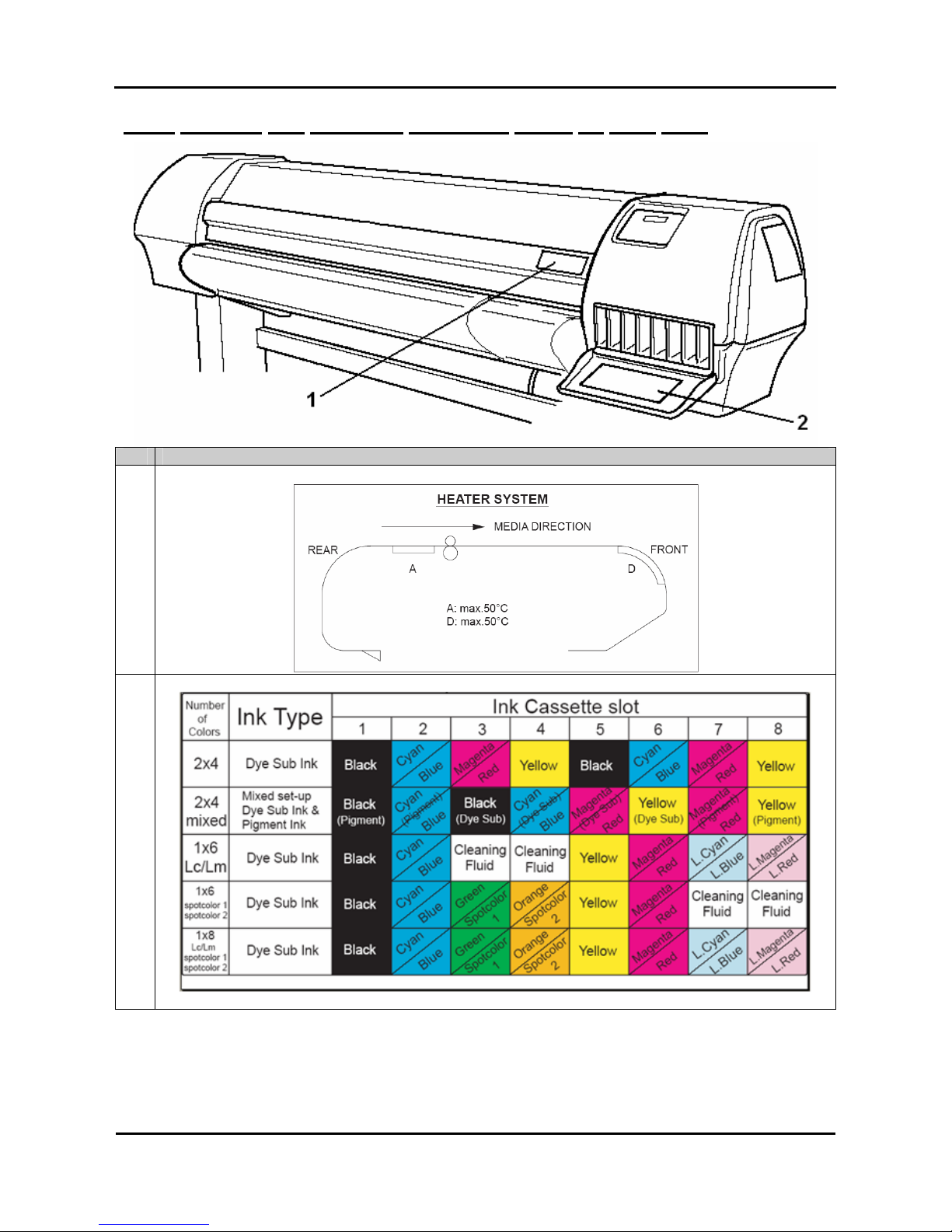
2.4.3. Position and function of the heating elements
Heater element Temperature Function
Pre-heater (Heater A) 20 – 50°C
→ The pre heater expands the transfer paper before it hits
the pinch rollers.
Dryer (Heater D) 20 – 50°C
→ The dryer helps to make the media touch-dry before it
reaches the automatic take-up system.
Page 32

Mutoh’s DT-Series Printers – Operation Instructions
32
AP-75171, Rev. 1.1, 25/06/04
2.5. ASSEMBLING THE UNIT
The assembly of this product is described below.
Caution :
When assembling this product, always work with at least 4 people or more.
2.5.1. Assembling the stand
Assemble the stand according to the following procedure.
Step 1 : Place the stand upside down as shown in the figure.
Step 2 : 2. Install the foot to the stay according to the following procedure.
A ) : Attach two feet on the bottom of the stay as shown.
B ) : Attach the hexagon socket head cap screws (M6 x 30: each 4) to each foot.
C ) : Using the assembly tool, tighten the hexagon socket head cap screws to install the feet.
1. Stay 2. Foot
3. Hexagon socket head cap screw (M6 x 30)
Step 3 : Assembling the stand has been completed.
Page 33

Mutoh’s DT-Series Printers – Operation Instructions
33
AP-75171, Rev. 1.1, 25/06/04
2.5.2. Installing the stand
Install the stand to the main unit according to the following procedure.
Step 1 : Place the stand with its feet on the floor.
Step 2 : Lift up the main unit with at least four persons by holding it by the handles.
Step 3 : Place the main unit on the stand.
1. Stand 2. Main unit
3. Handle
Step 4 : Attach the hexagon socket head cap screws (M6 x 16: 8) to the stand.
Step 5 : Tighten the hexagon socket head cap screws to install the stand using the assembly tool.
1. Hexagon socket head cap screw (M6 x 16) 2. Stand
3. Main unit
Step 6 : Installing the stand has been completed.
Page 34

Mutoh’s DT-Series Printers – Operation Instructions
34
AP-75171, Rev. 1.1, 25/06/04
2.5.3. Fixing the printer body onto the stand
After installation of the unit onto the stand, please check if there is no gap between the printer body and the
stand.
When you notice that there is a gap between the printer body and the stand, please follow the instructions
mentioned below to minimize this gap.
Notes :
Please find enclosed three types of spacers.
• 5 pieces : 0.3 mm spacer
• 5 pieces : 0.5 mm spacer
• 5 pieces : 1.0 mm spacer
Step 1 : In case there is a gap between the stand and the printer body, loosen the screw fixing the stand
to the unit.
Step 2 : Insert a spacer in-between the stand and the printer body.
Step 3 : Fully insert the spacer between the stand and the printer body.
Step 4 : Tighten the screw.
Page 35

Mutoh’s DT-Series Printers – Operation Instructions
35
AP-75171, Rev. 1.1, 25/06/04
2.5.4. Removal of protective packaging material
Protective packaging material is attached on following locations of this product.
Remove all protective packaging material according to the following procedure.
Step 1 : Remove tape from all parts of the product.
Step 2 : Remove the two anti-rubbing materials on the top of the main unit.
1. Anti-rubbing material
Step 3 : Remove the head unit fixture material from inside the front cover according to the following
procedure.
A ) : Open the front cover.
Caution :
Be careful not to pinch your fingers when opening and closing the front cover.
1. Front cover
Page 36

Mutoh’s DT-Series Printers – Operation Instructions
36
AP-75171, Rev. 1.1, 25/06/04
B ) : Remove the two wing bolts.
C ) : Remove the head unit fixture material.
1. Wing bolt 2. Head unit fixture material
D ) : Close the front cover.
1. Front cover
Step 4 : Remove the bag with media retainers taped onto the print platform.
Step 5 : Remove the dummy cassettes, the waste tube clamps and the bag enclosing the waste tub es.
Step 6 : Connect the waste tubes.
Step 7 : Removal of protective packaging material is completed.
Page 37

Mutoh’s DT-Series Printers – Operation Instructions
37
AP-75171, Rev. 1.1, 25/06/04
2.5.5. Installing the printer
To install the product, follow the steps below.
Step 1 : Move the product to where it will be installed.
Step 2 : Lock the casters.
Step 3 : Rotate the four adjusters in the direction shown in the figure to make the printer stable.
Step 4 : Jiggle the printer to make sure that it stable.
1. Adjuster 2. Caster
Caution :
¾ Make sure the unit is positioned stable and horizontal. Use a level.
Page 38

Mutoh’s DT-Series Printers – Operation Instructions
38
AP-75171, Rev. 1.1, 25/06/04
2.6. INSTALLING UNWINDER / WINDER 100 AND WASTE
BOTTLE
To install accessories, such as the unwinder / winder 100 and waste fluid bottle, please refer to the User’s
Guide “Handling roll media”.
Caution :
• Before installation and alignment of the unwinder / winder 100, please make sure
the printer is placed level!
It is important that the unwinder / winder 100 is perfectly lined out to prevent
cockling.
Caution :
• Before powering ON the unit, make sure the waste bottle is installed.
Page 39

Mutoh’s DT-Series Printers – Operation Instructions
39
AP-75171, Rev. 1.1, 25/06/04
3. PREPARING FOR A JOB
3.1. INTRODUCTION
The procedures needed before using the printer are explained below.
3.2. CONNECTING THE POWER CABLE
The connection procedure for the power cable is explained below.
Important :
• Make sure that the distributed power cable is used. Use of a different cable
may result in electric shock or fire.
• Do not use a damaged power cable. Doing so may result in electric shock or
fire.
• The disconnect device is the plug on the power supply cord.
Caution :
• Be careful of the following when handling the power cable.
o Do not make any modifications to the power cable.
o Do not place anything heavy on the power cable.
o Do not bend, twist, or pull the cable.
o Do not wire the cable near equipment that generates heat.
Notes :
• If the power cable is damaged, contact one of the following :
o The shop where you bought your MUTOH printer.
o Your local MUTOH dealer.
Page 40

Mutoh’s DT-Series Printers – Operation Instructions
40
AP-75171, Rev. 1.1, 25/06/04
To connect the power cable, follow the steps below.
Step 1 : Plug the power cable to the AC inlet on the back of the printer.
1. AC inlet 2. Power cable
Step 2 : Plug the cable correctly to the outlet.
Important :
• Do not attempt to plug in electrical plugs with wet hands. Doing so may
result in electrical shock.
• Be sure to use the specified voltage (AC 100V-120V/220V-240V). Otherwise,
electrical shock or fire may occur.
• Use electricity directly from a power outlet (AC 100V-120V/220V-240V). Do not
put many loads on one electrical output. Otherwise, heat may be generated
and cause fire.
• Be sure to use an outlet with an earth terminal, and use the terminal
correctly. Otherwise, electrical shock or fire may occur.
• Do not connect earth cables in the following areas :
o Gas pipes. Doing so may cause fire or an explosion.
o Earth terminals for telephone lines or lightening rods. Doing so may
cause a large flow of voltage if lightening occurs.
o Water pipes or faucets. If there is a plastic part in the pipe, the earth
will not work correctly.
Caution :
• Follow the instructions below when handling the power plug. Otherwise, fire may
occur.
o Wipe away dust and any other residue before inserting the plug.
o Ensure that the plug is firmly inserted as far as it will go.
• Ensure that the plug has been disconnected from the power socket when it is not
used for a long time.
• Earth wires must be connected to wires or terminals that fulfill the conditions :
o Earth terminals of power socket
o Earth wires with copper morsel that is at least 650 mm under ground
Page 41

Mutoh’s DT-Series Printers – Operation Instructions
41
AP-75171, Rev. 1.1, 25/06/04
Notes :
• If you cannot use earth terminals or find any of them, contact the shop where you
bought your printer.
• Do not unplug the power cable when the printer is on. If the power cable has been
unplugged, leave the printer for at least 1 minute before plugging the cable in
again.
1. Power cable
Page 42

Mutoh’s DT-Series Printers – Operation Instructions
42
AP-75171, Rev. 1.1, 25/06/04
3.3. CONNECTING THE FOOT SWITCH
The connection procedure for the foot switch is described below.
If the pressure roller needs to be raised or lowered, it is possible to control this motion from the foot switch,
instead of doing so at the operation panel.
Caution :
• When handling the foot switch, be aware of the following:
o Do not place anything heavy on the foot switch.
o Do not bend the cable of the foot switch with force and do not pull.
o Do not place the foot switch near thermal devices.
Install the foot switch according to following procedure.
Step 1 : Make sure that the power of the unit is OFF.
Notes :
• When the operation panel is in the following condition, the power is ON. Press the
key again to turn the power OFF.
o The POWER lamp is lit (green).
Step 2 : Connect the foot switch cable connector to the foot switch connector at the rear of the unit and fix
into place with a screw.
1. Foot switch connector 2. Foot switch cable
Page 43

Mutoh’s DT-Series Printers – Operation Instructions
43
AP-75171, Rev. 1.1, 25/06/04
Step 3 : Place the foot switch on the floor under the stand.
1. Foot switch
Page 44

Mutoh’s DT-Series Printers – Operation Instructions
44
AP-75171, Rev. 1.1, 25/06/04
3.4. CONNECTING THE PRINTER TO YOUR PC
Please find below some instructions how to connect the printer to your PC.
3.4.1. System requirements
To use your printer with the driver, you need a PC that fulfills the following system requirements.
System OS Windows 2000 Professional
CPU Pentium III 1 GHz or higher
Memory (RAM) 512 MB or more
Hard disk space 10 GB or more
Notes :
• The memory requirements may vary depending on the type of applications you are
using and the complexity of the document you want to print.
• MUTOH recommends you to use a hard disk and bulk memory as large as
possible.
3.4.2. Selecting cables
This printer is compatible with following interfaces :
¾ Centronics interface
¾ Network interface
The following cables are necessary to connect your printer to the computer. Prepare appropriate cables
according to the computer to be connected.
¾ Centronics interface: Centronics interface cable
¾ Network interface: 10BASE-T/100BASE-TX Ethernet cable that is compatible with both.
(Category 5)
Notes :
• See below for the connection procedure.
o Refer to ‘Connecting the Centronics interface’
o Refer to ‘Connecting the network interface’
• Refer to "Interface Specifications" for the connection procedure.
3.4.3. Connecting the Centronics interface
The procedure for connecting the Centronics interface is explained below.
To connect the printer to your computer, follow the steps below.
Step 1 : Turn off the printer and your computer.
Step 2 : Plug the cable connector of the interface cable into the interface connector at the back of the
printer. Squeeze the wire clips together until they lock into place.
Page 45

Mutoh’s DT-Series Printers – Operation Instructions
45
AP-75171, Rev. 1.1, 25/06/04
1. Centronics interface connector 2. Interface cable
Step 3 : Plug the other end of the cable into the computer's port.
Notes :
• Refer to your computer's manual for the procedure to connect to your computer.
3.4.4. Connecting the network interface
The procedure for connecting the network interface is explained below.
To connect the printer to the network environment, follow the steps below.
Caution :
• Follow the instructions below when connecting the network interface cable.
Otherwise, electrical shock or fire may occur.
o Do not touch the connector.
o Do not connect the network cable connector to the interface board having
different specifications.
Step 1 : Turn off the printer.
Step 2 : Plug the connector of the Ethernet cable into the connector of the network interface board at the
back of the printer.
Page 46

Mutoh’s DT-Series Printers – Operation Instructions
46
AP-75171, Rev. 1.1, 25/06/04
1. Network interface connector 2. Interface cable
Step 3 : Connect the other end of the Ethernet cable to the network.
Notes :
• Refer to "Network interface board operation manual" to use the network interface
board.
Page 47

Mutoh’s DT-Series Printers – Operation Instructions
47
AP-75171, Rev. 1.1, 25/06/04
3.5. TURNING THE POWER ON/OFF
The method to turn the power ON or OFF is described below.
Caution :
¾ Before powering ON the unit for the first time, make sure to:
Remove the dummy cassettes
Remove the waste tube clamps
Remove the bag enclosing the waste tubes
Connect the waste tubes
3.5.1. Turning the power ON
Turn the power of the unit ON according to following procedure.
Step 1 : Press the [POWER] key of the operation panel, to turn the unit ON.
¾ The POWER lamp of the operation panel will light (green).
Step 2 : The unit will initial startup operations.
Step 3 : After finishing initial startup operations, the unit will enter the normal operating condition.
Notes :
• If there are any problems during the initial startup operation, the unit will display a
message on the operation panel, and the operation may stop. If the operation
stops, refer to "Troubleshooting", and take the appropriate actions.
Page 48

Mutoh’s DT-Series Printers – Operation Instructions
48
AP-75171, Rev. 1.1, 25/06/04
3.5.2. Turning the power OFF
Turn the power of the unit OFF according to the following procedure.
Step 1 : Verify the following regarding the operational condition of the unit.
¾ There is no printing operation being performed.
¾ The operation panel is in a normal status.
Step 2 : Press the [POWER] key of the operation panel to turn the unit OFF.
Notes :
• When the operation panel is in the following condition, the power is ON. Press the
key again to turn the power OFF.
o The POWER lamp is lit (green).
Step 3 : Following message is displayed for 3 seconds on the operation panel.
Notes :
• If pressing the [POWER] key on the operation panel by mistake, press the
[POWER] key again while the following message is displayed.
Power OFF
Page 49

Mutoh’s DT-Series Printers – Operation Instructions
49
AP-75171, Rev. 1.1, 25/06/04
Step 4 : The product will perform the power OFF operation.
¾ Following message is displayed on the operation panel.
Power OFF
Please Wait
¾ All lamps and the LCD of the operation panel will turn OFF.
¾ The product will automatically turn the power OFF.
Notes :
• If there are problems during the power OFF operation, the unit will display a
message on the operation panel, and the operation may stop. If the operation
stops, refer to “Troubleshooting” and take the appropriate actions.
Page 50

Mutoh’s DT-Series Printers – Operation Instructions
50
AP-75171, Rev. 1.1, 25/06/04
3.6. INSTALLING INK CASSETTES
The installation of ink cassettes for the first time into the unit is explained below.
Caution :
• Before powering ON the unit, make sure the waste bottle is installed, the clamps of
the waste tubing are removed and the dummy cassettes are removed.
Caution :
¾ When handling ink cassettes, be careful that ink does not get in your eyes or on your
skin. However, if this happens, flush immediately with water. Otherwise, your eyes
may become congested or inflamed slightly. If you feel discomfort, consult a doctor
immediately.
¾ Do not disassemble ink cassettes. Otherwise, ink may get in your eyes or on your
skin.
¾ Do not shake ink cassettes strongly. Otherwise, ink may leak.
Notes :
The unit is delivered / shipped with special shipping liquid. This to prevent air coming
into the ink supply system. Make sure that air never comes into the ink supply system.
To install ink cassettes, follow the steps below.
Caution :
¾ Before powering ON the unit for the first time, make sure to:
Remove the dummy cassettes
Remove the waste tube clamps
Remove the bag enclosing the waste tubes
Connect the waste tubes
Step 1 : Before powering ON the unit for the first time, please be sure to have :
¾ 8 cleaning cassettes compatible with the ink
¾ 8 ink cassettes of the requested ink configuration
Step 2 : Check if the Waste Bottle is empty.
Page 51

Mutoh’s DT-Series Printers – Operation Instructions
51
AP-75171, Rev. 1.1, 25/06/04
Step 3 : Power ON the unit.
Caution :
The unit is shipped with a water based shipping liquid. If there is any doubt about
compatibility with your ink, perform a cleaning cycle before loading ink (step 4 to step 6).
If not proceed to step 7.
Step 4 : In the “Ink Manager” menu select “Wash” and then “All”. Confirm your selection. The display will
ask you to install the cleaning cassettes (‘Please insert Cleaning Cart’).
¾ Install the 8 NEW cleaning Cassettes (compatible with the ink).
1. Ink cassette slot 2. Cleaning cassette
Press the [ENTER] key.
The display will show the following message.
During washing
Wait for a while
10 min
During washing
Wait for a while
0 min
Step 5 : The display will show the following message.
Please remove
cartridges
Step 6 : Remove all the cleaning cassettes.
Ink status
No cartridge (ALL)
Page 52

Mutoh’s DT-Series Printers – Operation Instructions
52
AP-75171, Rev. 1.1, 25/06/04
Step 7 : Insert ink cassettes in the requested configuration.
• The ink cassette must be put in a specific slot according to the type and colour used.
• Insert the cassette with the arrow mark face-up and pointing to the rear of the printer.
• Insert the cassette as far as possible.
1. Ink compartment
Step 8 : Go to the ‘ink Manager’ menu, select ‘Inkload’ and select ‘All’. Confirm your selection.
Filling ink
rest 11 min
Filling ink
rest 0 min
Step 9 : The installation of ink in the unit has been completed.
Caution :
• Please wait at least 30 minutes before printing after loading ink. This to allow the
ink to settle in the print heads.
Notes :
• During washing and ink loading, note the following.
o Do not power off the printer.
o Do not unplug the power cable.
o Do not open the front cover.
Step 10 : Choose the appropriate ink configuration in the smart-chip menu or manual menu.
Page 53

Mutoh’s DT-Series Printers – Operation Instructions
53
AP-75171, Rev. 1.1, 25/06/04
3.7. MEDIA HANDLING
Media handling, attaching media and setting media type are explained below.
Environmental Recommended
working environment
Temperature: 19°C – 26°C
Humidity: 30% to 60%, without condensation
Notes :
Please note that some inks require a humidity of more than 50%, other inks can be used
at 30% humidity. Please contact your ink supplier for optimum printing conditions.
Caution :
• The size of the media can change at a fixed ratio according to the temperature
changes of the working environment. Before using media, place the media roll in
the working environment for at least 24 hours, to have it match to the temperature
of the working area.
• Printing before the media could accommodate to the printing environment may
cause media jams due to slippage or creases. This also adversely effects the
quality of printing.
3.7.1. Loading roll media
The unwinder / winder 100 system always provides an equal tension on the media when printing.
It is important that the unwinder / winder 100 is perfectly lined out to prevent cockling. To line out the
unwinder / winder 100, please refer to the user’s guide “Handling Roll Media”.
Caution :
• Before installation and alignment of the unwinder / winder 100, please make sure
the printer is placed level!
Caution :
• Media detection utility should be set on “Rollfeed”.
Page 54

Mutoh’s DT-Series Printers – Operation Instructions
54
AP-75171, Rev. 1.1, 25/06/04
Caution :
• It is very important to set the correct media thickness.
Please find below a short resume of installation of roll media.
Notes :
• Please also refer to the section “Unwinder / winder 100” of the user’s guide
“Handling roll media”.
Step 1 : Make sure the printer and unwinder / winder 100 are ON.
Step 2 : Press the [F4] key to raise the pressure roller.
Step 3 : Open the front cover.
Step 4 : Put the media roll between the motorized roll unit and roll unit of the unwinder unit.
a. Position in the middle of the printer (use hole pattern in the steel bar).
b. Make sure no slip occurs.
1 : Holes in the steelbar
Step 5 : Install an empty core between the motorized roll unit and roll unit of the winder unit on front of the
printer. -→ Make sure the core is longer than the media width.
Step 6 : Make sure both unwinder (REAR) and winder (FRONT) unit are set to MANUAL mode.
Step 7 : Use the foot-switch to release some media on the rear.
Page 55

Mutoh’s DT-Series Printers – Operation Instructions
55
AP-75171, Rev. 1.1, 25/06/04
Step 8 : Load media through the rear tensioning system as described below.
1 = Unwinder System 2 = Rear Tension System
3 = Insertion slot
Step 9 : Load the media through the printer’s pressure rollers.
Step 10 : On front of the printer, take the media and pull straight (until you become an equal tension on the
left and right of the media).
Notes :
• Make sure the rear tensioning system is turned against the unit.
Page 56

Mutoh’s DT-Series Printers – Operation Instructions
56
AP-75171, Rev. 1.1, 25/06/04
Step 11 : Set the unwinder (REAR) unit to AUTOMATIC until the media reaches the empty core and the
rear tensioning system is turned against the unit.
Step 12 : Set the unwinder (REAR) unit to MANUAL.
Step 13 : Use some tape to fix the media end to the empty core installed at the winder unit. Start taping
the middle of the media. Then the both ends. Do not apply tension on the media.
Step 14 : Lower the pressure rollers.
Step 15 : Set the winder and unwinder units AUTOMATIC.
Step 16 : Close the front cover.
Step 17 : Installation of the media is completed.
Caution :
• Make sure the media is loaded straight.
Caution :
• After installation of media, be sure that the correct media thickness is set!
Page 57

Mutoh’s DT-Series Printers – Operation Instructions
57
AP-75171, Rev. 1.1, 25/06/04
Notes :
With a small intervention it is possible to reverse your winding direction.
Mount a cable between the control box and the front motorized unit cable.
3.7.2. Setting media type
The procedure for setting media type is explained below.
To set the media type, follow the steps below.
Step 1 : Turn the printer on and load the media.
¾ Once the media has been set, the media initial menu will be displayed.
Notes :
• Refer to following sections to load media :
o Loading media
Step 2 : Press one of the following keys on the operation panel, and select the current media type.
¾ When alternating roll/sheet media selection: [F2]
¾ When changing from media loading: [F3]
¾ When changing media type: [F4]
* PaperInitialMenu *
Roll
← F2
F3 →
LeverUp User1
← F4
F2, F4 → ENTER or F3
Page 58

Mutoh’s DT-Series Printers – Operation Instructions
58
AP-75171, Rev. 1.1, 25/06/04
Setup items
Key Parameters Description
Roll media Media type F2
Sheet media
Alternates the roll media type.
• Roll media : Set when loading roll media.
• Sheet media : Set when loading sheet media.
Lever up Lever Down/Up F3
Lever down
Switches between up and down motion of the
pressurizing lever.
Use this when starting over from the media setup.
User 1
User 2
User 3
User 4
User 5
User 6
User 7
Media Type F4
User 8
Set media type for printing.
For setup values of printing operation, eight settings
of "user 1-8" can be set.
Refer to ‘Menu setup on the operation panel’
Step 3 : Press the [Enter] key on the operation panel.
¾ The media type has been set.
¾ "Media Initial" is displayed on the LCD, and the printer starts the media initial operation.
Notes :
• The printer starts the media initial operation if you :
o Press the [CANCEL] key on the operation panel
o Leave the printer for 10 seconds without doing anything
Paper Initial
User 1
Step 4 : When the media initial operation finishes, the printer moves to normal status.
¾ The setting media loading procedure has been completed.
Print OK
Heaters Cleaning
Cut&Feed Lever Up
User1 xxxm
Page 59

Mutoh’s DT-Series Printers – Operation Instructions
59
AP-75171, Rev. 1.1, 25/06/04
3.8. MEDIA RETAINERS (MEDIA HOLDER)
The media cockling causes the transfer paper edges to curl. Media retainers keep the media edges pushed
down on the print platform.
Caution :
• When using roll media, we recommend you to always use the media retainers.
Notes :
• When using sheet media, media retainers are not necessary used. If used, please
make sure the media is loaded correctly straight. Otherwise, media can slant and
the media retainers could tear the transfer paper.
Use the following procedure to install the media retainers (media holders).
Caution :
• When using media holder, make sure to firmly set it to the platen of the printer unit.
In case the media holder declines or loosens, it might hit the print head and cause
trouble.
Notes :
• When using the media holder, please do the following :
• Set to “Normal” or “TakeupReel” on the Media Detection menu.
• When setting the Media Detection menu to off, define a smaller value than
the media width on the Media Width menu.
Step 1 : Verify if the media initial operation has been finished.
Step 2 : Open the front cover.
Page 60

Mutoh’s DT-Series Printers – Operation Instructions
60
AP-75171, Rev. 1.1, 25/06/04
Step 3 : Attach the media holder (left, right) to both sides of the roll media. First attach the rear side of
the media retainer to the rear of the print platform.
Step 4 : Push the front side of the media retainer down to set it.
Step 5 : Close the front cover.
Page 61

Mutoh’s DT-Series Printers – Operation Instructions
61
AP-75171, Rev. 1.1, 25/06/04
To remove the media retainers, please follow the instructions below.
Step 1 : Carefully pull the lid towards you and unlock the media retainer from behind the print platform.
OK NOT OK
Page 62

Mutoh’s DT-Series Printers – Operation Instructions
62
AP-75171, Rev. 1.1, 25/06/04
3.9. USING THE ETT SYSTEM
The ETT Extra Tension Tool pulls the media in line with the print platform. The tension on the sides is
always bigger than in the middle. As a result possible curls are straightened.
Notes :
• Always make sure that the edges of the media are supported by the edges of the
ETT.
• Only use the middle part of the ETT if media width is larger than 51” (for 65” printer)
• Only use the middle part of the ETT if media width is larger than 75” (for 90” printer)
Step 1 : There is no media loaded in the printer. Bring the ETT-holding-bar forward. (Handle is placed
horizontally.)
Step 2 : Install the ETT’s on the ETT-holding-bar.
Notes :
• There are three different ETT’s : a Left-ETT, a middle-ETT and a Right-ETT.
• Please note that the outer sides of the Right and Left-ETT have longer springs than
the insides!
Page 63

Mutoh’s DT-Series Printers – Operation Instructions
63
AP-75171, Rev. 1.1, 25/06/04
When using media larger than 51”, install all three ETT’s.
When using media smaller than 51”, install only the Left and Right-ETT’s.
Place all ETT’s on the ETT-holding-bar.
Page 64

Mutoh’s DT-Series Printers – Operation Instructions
64
AP-75171, Rev. 1.1, 25/06/04
Secure all ETT’s to the ETT-holding-bar with the secure knob.
Step 3 : Bring the ETT-holding-bar backward with all ETT’s attached : Handle is placed vertically.
Step 4 : Install the roll media. (Please refer to loading roll media.)
Step 5 : Bring the ETT-holding-bar with the previously installed ETT’s forward. The extra tension is set to
the outer sides.
Notes :
• Wait to pull the ETT-lever until the printed area has passed over the print platform.
Page 65

Mutoh’s DT-Series Printers – Operation Instructions
65
AP-75171, Rev. 1.1, 25/06/04
3.10. PRESSURE ROLLERS DISABLER TOOL
The pressure roller disabler tool allows a pressure roller to be lifted while printing, thus providing the
necessary space for media to expand.
Caution :
• When using roll media, we recommend you to use two pressure rollers disabler
tools on both outer sides of the media, as well as two on 1/3 and two on 2/3 of the
media.
• It is not necessary to use pressure rollers disabler tools when using sheet media.
Step 1 : Take the pressure roller disabler tool as follows in your right hand.
Page 66

Mutoh’s DT-Series Printers – Operation Instructions
66
AP-75171, Rev. 1.1, 25/06/04
Step 2 : Pull the pressure roller (you want to disable) down with your left index finger.
Step 3 : Place the pressure roller disabler tool in the space created when pulling the pressure roller down.
Caution :
• Be sure not to push the pressure roller disabler tool too far! Otherwise the pressure
roller will break.
Page 67

Mutoh’s DT-Series Printers – Operation Instructions
67
AP-75171, Rev. 1.1, 25/06/04
The pressure roller disabler tool is now positioned as follows :
Page 68

Mutoh’s DT-Series Printers – Operation Instructions
68
AP-75171, Rev. 1.1, 25/06/04
3.11. CONTROLLING THE HEATER ELEMENTS
If you want to change or check the heater elements, follow the steps below.
Step 1 : Press the [F1] key on the operation panel.
¾ The printer works as follows.
Print OK
F1 →
Heaters Cleaning
← F2
F3 →
Cut&Feed LeverUp
← F4
User1 xxxm
By pressing the [F1] key, you will have direct access to control or change the heaters
temperatures.
After pressing the [F1] key in the normal status, the operation panel will mention the following :
* Heaters *
F1 →
A : S 50 – R 50
F3 →
D : S 50 – R 50 SET ON
← F4
heater message
The ‘heater message’ can be one of the following :
Heater standby
Heater warming up
Heater ready
‘A’ stands for the rear heaters.
‘D’ stands for the dryers.
‘S’ stands for the Set-temperature (requested temperature).
‘R’ stands for the Real-temperature (actual temperature).
3.11.1. Change the rear heater temperature
To change the temperature of the rear heaters, press the [F1] key on the operation panel. The display will
mention the following :
* Heater (A) *
OFF – 50°C +
← F2
50°C -
← F4
F2, F4
→ ENTER
Press the [F2] key to decrease the temperature.
Press the [F4] key to increase the temperature.
Press the [ENTER] key to confirm the requested temperature change.
Press the [CANCEL] key to leave the menu without changing the rear heater settings.
Page 69

Mutoh’s DT-Series Printers – Operation Instructions
69
AP-75171, Rev. 1.1, 25/06/04
Caution :
• We recommend you to set the pre-heater temperature at 50°C. This to be sure that
transfer paper is already expanded a little before reaching the pressure rollers.
3.11.2. Change the dryer temperature
To change the temperature of the dryers, press the [F3] key on the operation panel. The display will mention
the following :
* Drier (D) *
OFF – 50°C +
← F2
50°C -
← F4
F2, F4
→ ENTER
Press the [F2] key to decrease the temperature.
Press the [F4] key to increase the temperature.
Press the [ENTER] key to confirm the requested temperature change.
Press the [CANCEL] key to leave the menu without changing the rear heater settings.
Caution :
• We recommend you to set the dryer temperature at 50°C. This to be sure that
transfer paper is touch-dry when winded.
3.11.3. Activate/ disactivate heaters.
By pressing the [F4] key you can activate or disactivate all heating elements.
In case the heating elements are activated, the display will mention “SET OFF”. By pressing the [F4] key
you can disactivate the heating elements. The display will mention “SET ON”.
In case the heating elements are disactivated, the display will mention “SET ON”. By pressing the [F4] key
you can activate the heating elements. The display will mention “SET OFF”.
Please note that after finishing a printing job (and no other print job is sent to the printer the heating elements
will keep their temperature for approximately 6 minutes. After 6 minutes the heating elements are powered
OFF.
Page 70

Mutoh’s DT-Series Printers – Operation Instructions
70
AP-75171, Rev. 1.1, 25/06/04
Page 71

Mutoh’s DT-Series Printers – Operation Instructions
71
AP-75171, Rev. 1.1, 25/06/04
4. DAILY MAINTENANCE
4.1. REPLACING INK CASSETTES
Read the following for information on when and how to replace ink cassettes.
(1) Replacement time
Replace ink cassettes under the following conditions.
a. The ink remaining in the ink cassette is low.
• The following message is displayed on the operation panel.
• Printing operation is continued.
• Prepare new ink cassettes before they are totally empty.
Ready to Print
Heaters Cleaning
Cut&Feed LeverUp
→
NearEnd [1]
b. The ink cassette becomes empty.
• The following message is displayed on the operation panel.
• Printing operation stops.
• Replace with a new ink cassette as soon as possible.
InkStatus
No Ink [123]
Notes :
• When the ink runs out or is low, the ink colour is indicated as follows:
• 1-8: The number of the ink cassette slot (Refer to ‘Installing ink cassettes’)
• All: All inks
(2) Replacement procedure
Follow the steps below to replace ink cassettes.
Caution :
• When handling ink cassettes, be careful that ink does not get in your eyes or on
your skin. However, if this happens, flush immediately with water.
Otherwise, your eyes may become congested or slightly inflamed. If you feel
discomfort, consult a doctor immediately.
• Do not disassemble ink cassettes. Otherwise, ink may get in your eyes or on your
skin.
Do not shake ink cassettes. Doing so may cause ink to leak out.
Page 72

Mutoh’s DT-Series Printers – Operation Instructions
72
AP-75171, Rev. 1.1, 25/06/04
Step 1 : If the printer is turned on, make sure of the following
• Printing or other operations are not performed.
• Make sure that the display on the operation panel shows the normal state.
• The MEDIA SET light on the operation panel goes off.
Step 2 : Open the ink compartment cover.
Caution :
• Be sure not to pinch your fingers while opening and closing the ink compartment
cover.
1. Ink Compartment
Step 3 : Remove the ink cassette from the ink cassette slot.
Notes :
• Dispose the used ink cassette by putting it in a plastic bag in accordance with
local regulations or laws.
1. Ink cassette slot 2. Ink cassette
Page 73

Mutoh’s DT-Series Printers – Operation Instructions
73
AP-75171, Rev. 1.1, 25/06/04
Step 4 : Take the new ink cassette from its package.
Notes :
Unpack the ink cassette just before installing it into the ink cassette slot. If you leave the
cassette unpacked for a long time, the printer may not be able to print correctly.
Use up ink cassettes within two years from the date printed on the cassette packages.
Replace ink cassettes if after six months since installation.
Step 5 : Install the ink cassette following the steps in "Installing ink cassettes".
Step 6 : Close the cover of the ink compartment.
1. Ink Compartment
Step 7 : Make sure that the display on the operation panel returns to normal status.
Notes :
• If you replace ink cassettes while printing, the printer resumes printing.
Page 74

Mutoh’s DT-Series Printers – Operation Instructions
74
AP-75171, Rev. 1.1, 25/06/04
4.2. REPLACING THE CUTTING BLADE
Read following information on when and how to replace the cutting blade.
(1) Replacement time
Replace the cutting blade under the following conditions.
a. Media cannot be cut cleanly
The message "media Cut Error" appears on the operation panel if a media cutting error occurs.
→
Paper Cut Error
Heaters Cleaning
Cut&Feed LeverUp
User1 xxxm
b. When the cut edge has scuffing
(2) Replacement procedure
Follow the steps below to replace the cutting blade.
Step 1 : If the printer is turned on, make sure of the following
¾ Printing or other operations are not performed.
¾ Make sure that the display on the operation panel shows the normal status.
¾ The MEDIA SET light on the operation panel goes off.
Step 2 : Follow "Menu setup on the operation panel" and display the cutting blade replacement menu on
the operation panel.(Refer to ‘Cutter change menu’)
* CutterChg. *
No Yes
← F2
(1/1)
Step 3 : Select "Yes" by pressing the [F2] key on the operation panel.
¾ The printer prepares for cutting blade replacement.
¾ The carriage moves to the cutting blade replacement position.
¾ The following message is displayed on the operation panel.
Notes :
• If you did one of the things mentioned in step 3, the printer does not replace the
cutting blade and returns to the setup menu.
• Press the [CANCEL] key on the operation panel.
• Select "NO" then press the [F1] key on the operation panel.
Page 75

Mutoh’s DT-Series Printers – Operation Instructions
75
AP-75171, Rev. 1.1, 25/06/04
* CutterChg. *
Changed cutter?
→ ENTER
Step 4 : Open the front cover.
1. Front cover
Notes :
• Replace the cutting blade as quickly as possible. If you leave the carriage at the
cutting blade replacement position, the head may be clogged with ink.
Step 5 : While pressing the cutting blade holder tab, rotate the cutting blade holder lever in the direction
shown in the diagram.
Notes :
• Do not push the cutting blade holder tab strongly or release it suddenly. Doing
so may cause the spring incorporated in the cutting blade holder to fly off.
• Do not push in the cutting blade holder. Doing so may cause the cutting blade
to damage the inside of the printer.
1. Cutting blade holder lever 2. Cutting blade holder
Page 76

Mutoh’s DT-Series Printers – Operation Instructions
76
AP-75171, Rev. 1.1, 25/06/04
Step 6 : Take out the cutting blade.
Caution :
• Do not touch the edge of the cutting blade to avoid injury.
• Do not drop the cutting blade or apply it on hard material. Doing so may
damage or break the cutting blade.
Notes :
• Dispose the used cutting blade, put it in a plastic bag in accordance with local
regulations or laws.
1. Cutting blade
Step 7 : Insert the new cutter into the media cutting blade holder as shown below.
Notes :
• Be sure not to let the spring incorporated in the cutter holder fly out.
1. Cutting blade
Page 77

Mutoh’s DT-Series Printers – Operation Instructions
77
AP-75171, Rev. 1.1, 25/06/04
Step 8 : While slightly pressing the cutting blade holder tab, return the cutting blade lever to its original
position.
Notes :
• Do not push the cutting blade holder tab strongly or release it suddenly. Doing
so may cause the spring incorporated in the cutting blade holder to fly off.
• Do not push in the cutting blade holder. Doing so may cause the cutting blade
to damage the inside of the printer.
• Attach the cutting blade holder lever correctly, referring to the diagram below. If
it is not attached correctly, errors may occur.
If an error occurs, make sure that the cutting blade holder lever is attached
correctly.
1. Cutting blade holder lever 2. Cutting blade holder
Step 9 : Close the front cover.
1. Front cover
Page 78

Mutoh’s DT-Series Printers – Operation Instructions
78
AP-75171, Rev. 1.1, 25/06/04
Step 10 : Press the [ENTER] key on the operation panel.
¾ The carriage returns to its original position and returns to menu 6/7.
* SetupMenu *
F1 →
CutterChg. WiperClean
← F2
F3 →
TankChg. TubingFlush
← F4
(6/7)
¾ The printer returns to the normal status when pressing the [CANCEL] key.
Ready to Print
Heaters Cleaning
Cut&Feed LeverUp
User1 xxm
Step 11 : Cutting blade replacement has been finished.
Page 79

Mutoh’s DT-Series Printers – Operation Instructions
79
AP-75171, Rev. 1.1, 25/06/04
4.3. REPLACING THE WASTE LIQUID TANK
Read following information on when and how to replace the waste liquid tank.
(1) Replacement Time
Replace the waste liquid tank under the following conditions.
a. When the waste liquid tank is nearly full.
• Following message is displayed on the operation panel.
• Printing continues.
• Prepare a new waste liquid tank before the waste liquid tank becomes full.
→
Warning WastInkTank
Heaters Cleaning
Cut&Feed LeverUp
User1 Om
(2) Replacement Procedures
Follow the steps below to replace the waste liquid tank.
Step 1 : Check the following if the power of the printer is ON.
¾ Printer is not printing.
¾ Operation panel is in normal status.
¾ Media setting light on the operation panel is off.
Step 2 : Follow "Menu setup on the operation panel" and display the tank replacement menu on the
operation panel. (Refer to ‘Tank change menu’)
* TankChg. *
No Yes
← F2
(1/1)
Changed wasted ink tank?
ENTER or CANCEL
Step 3 : Open the cap of the waste liquid tank.
Caution :
• Do not bend or pull the waste fluid tube. Doing so may cause that the waste
fluid will leak out and malfunction in the product.
Page 80

Mutoh’s DT-Series Printers – Operation Instructions
80
AP-75171, Rev. 1.1, 25/06/04
Step 4 : Remove the waste liquid tank from the tank tray of the stand.
Notes :
• Put the used waste liquid tank in a plastic bag and follow the local regulations
when disposing.
Step 5 : Open the cap of a new waste liquid tank and put the tank to the printer.
Step 6 : Press the [ENTER] key on the operation panel.
• The printer returns to menu 6/7.
* SetupMenu *
F1 →
CutterChg. WiperClean
← F2
F3 →
TankChg. TubingFlush
← F4
(6/7)
• The printer returns to the normal status by pressing the [CANCEL] key
Ready to Print
Heaters Cleaning
Cut&Feed LeverUp
User1 xxxm
The replacement of the waste liquid tank has been completed.
Page 81

Mutoh’s DT-Series Printers – Operation Instructions
81
AP-75171, Rev. 1.1, 25/06/04
4.4. CLEANING
You need to clean the printer periodically to keep it in best working condition.
Warning:
• Do not insert or drop metal or inflammable objects into openings, such as
ventilation outlets. Doing so may result in electrical shock and fire.
• Stop using your printer if a liquid is spilled into it. This may cause
electrical shock or fire. Power the printer OFF as soon as possible, unplug
the power cord and then contact your local MUTOH dealer.
Caution:
• Be sure to power OFF the printer and unplug the power cable from the outlet
before cleaning the printer.
• Do not use thinner, benzene, alcohol or other active agents. Doing so may
result in damage or paint peeling from the casing.
• Be careful not to spill liquid inside the printer. Doing so may result in a short
circuit.
• Never open the covers fixed with screws. Doing so may result in electrical
shock or malfunctioning of the printer.
Following are instructions for cleaning the printer.
4.4.1. Cleaning the outer case
(1) Cleaning frequency
Clean once a month.
(2) Cleaning procedure
Remove dust or smudges on the outer case with a soft cloth.
Page 82

Mutoh’s DT-Series Printers – Operation Instructions
82
AP-75171, Rev. 1.1, 25/06/04
4.4.2. Cleaning the inside of the printer
(1) Cleaning frequency
Clean once a month.
(2) Cleaning procedure
The following are instructions for cleaning the inside of the printer.
Follow the steps below.
Step 1 : Open the front cover.
1. Front cover
Step 2 : Use a soft brush to carefully clean away any dust or dirt on the pressure rollers.
Notes :
• Do not blow off media dust inside the printer using an air dusting machine.
Doing so may cause noise to occur from inside the printer.
Step 3 : Use a cloth soaked in cleaning liquid and squeeze it well, wipe off media dust and ink from the
platen.
Caution :
¾ Please only use cleaning liquid recommended by the ink supplier.
Page 83

Mutoh’s DT-Series Printers – Operation Instructions
83
AP-75171, Rev. 1.1, 25/06/04
4.4.3. Head cleaning
If printouts become faint or partially missed, perform head cleaning to clean the surface of the head and the
nozzles.
Follow the steps below to perform head cleaning.
Step 1 : Refer to "Testprinting" to perform nozzle check printing.
Step 2 : Check if the print head, referring to the diagram below.
Notes :
¾ Above each nozzle check a number appears. Use this number to choose the
appropriate cleaning procedure.
Step 3 : Check if the printer is in the normal status.
Ready to Print
Heaters Cleaning
← F2
Cut&Feed LeverUp
User1 xxxm
Step 4 : Press the [F2] key on the operation panel.
¾ The printer enters the cleaning menu.
* Cleaning *
F1 →
All Normal
← F2
F1, F2
→ ENTER
Step 5 : Press the [F2] key on the operation panel to change the parameters.
Key Parameter Description
All Performs the selected cleanings to all head s.
Head 1 Performs the selected cleaning to the nozzle checks indicated with number 1.
Head 2 Performs the selected cleaning to the nozzle checks indicated with number 2.
Head 3 Performs the selected cleaning to the nozzle checks indicated with number 3.
F1
Head 4 Performs the selected cleaning to the nozzle checks indicated with number 4.
Little Little cleaning is performed. Heads fire some ink in ca pping.
Normal Normal cleaning is performed. A small amount of ink is sucked out of the heads.
A wipe is performed.
F2
Powerfull Powerfull cleaning is performed. A larger amount of ink is sucked out of the
heads. A wipe and a rub are performed.
Page 84

Mutoh’s DT-Series Printers – Operation Instructions
84
AP-75171, Rev. 1.1, 25/06/04
Step 6 : Press the [ENTER] key on the operation panel to start the head cleaning.
Notes :
• If the [Cancel] key has been pressed instead of the [ENTER] key after changing
the parameters, the printer returns to the normal status without performing a
head cleaning.
Cleaning
Rest ** min
Step 7 : When the head cleaning has been completed, the printer returns to the normal status.
Ready to Print
Heaters Cleaning
Cut&Feed LeverUp
User1 xxxm
Step 8 : Perform a nozzle check again and check the print head.
Page 85

Mutoh’s DT-Series Printers – Operation Instructions
85
AP-75171, Rev. 1.1, 25/06/04
4.4.4. Cleaning the cleaning wiper
Following are instructions for cleaning the cleaning wiper.
Follow the steps below to clean the cleaning wiper.
Step 1 : If the printer is turned on, make sure of the following
¾ Printing or other operations are not performed.
¾ Make sure that the display on the operation panel shows the normal status.
¾ The MEDIA SET light on the operation panel goes off.
Step 2 : Follow "Menu setup on the operation panel" and display the cleaning wiper menu on the
operation panel.(Refer to ‘Wiper clean menu’)
* SetupMenu *
F1 →
CutterChg. WiperClean
← F2
F3 →
TankChg. TubingFlush
← F4
(6/7)
* WiperClean *
No Yes
← F2
(1/1)
Step 3 : Select "Yes" by pressing the [F2] key on the operation panel.
¾ The printer enters the cleaning wiper mode.
¾ The carriage moves to the waiting position for cleaning the wiper.
¾ The following message is displayed on the operation panel.
Notes :
• If you did one of the things mentioned below, the carriage moves back and the
printer returns to the setup menu.
• Press the [CANCEL] key on the operation panel.
• Select "No" and press the [F1] key on the operation panel.
* WiperClean *
Changed wiper ?
→ ENTER
Step 4 : Open the front cover.
Caution :
• Be sure not to pinch your fingers while opening and closing the front cover.
Page 86

Mutoh’s DT-Series Printers – Operation Instructions
86
AP-75171, Rev. 1.1, 25/06/04
1. Front cover
Caution :
• Do not touch the cleaning wiper or the head cap unit while cleaning the cleaning
wiper. Doing so may result in poor head cleaning because of oil on your hands.
Step 5 : Use a dust free cloth dampened with cleaning liquid to wipe off ink on the cleaning wiper.
1. Cleaning wiper 2. Cleaning cloth
3. Head cap unit
Caution :
¾ Please only use cleaning liquid recommended by the ink supplier.
Step 6 : Press the [ENTER] key on the operation panel.
¾ The carriage moves to the cap position. The printer returns to menu 6/7.
* SetupMenu *
F1 →
CutterChg. WiperClean
← F2
F3 →
TankChg. TubingFlush
← F4
(6/7)
¾ The printer returns to the normal status after pressing the [CANCEL] key
Ready to Print
Heaters Cleaning
Cut&Feed LeverUp
User1 xxxm
Step 7 : Cleaning the wiper has been finished.
Page 87

Mutoh’s DT-Series Printers – Operation Instructions
87
AP-75171, Rev. 1.1, 25/06/04
5. UNDERSTANDING THE OPERATION
PANEL & PRINTER CONTROLS
5.1. OPERATION PANEL
The operation panel is used to set operational conditions, display the status of the printer, and set other
functions.
The names and functions of the operation keys and status lamps are explained below.
(1) Operation keys
No. Name Normal Setup menu display
1 [POWER] key Turns the printer on and off. Turns the printer on and off.
2 [F1] key Executes the function assigned to F1. Executes the function as signed to F1.
3 [F2] key Executes the function assigned to F2. Executes the function as signed to F2.
4 [F3] key Executes the function assigned to F3. Executes the function as signed to F3.
5 [F4] key Executes the function assigned to F4. Executes the function as signed to F4.
6
[MENU ↑] key
Changes the LCD monitor display to
the setup menu status.
Changes the menu in reverse order.
7
[MENU ↓] key
Changes the LCD monitor display to
setup menu status.
Changes the menu in forward order.
Page 88

Mutoh’s DT-Series Printers – Operation Instructions
88
AP-75171, Rev. 1.1, 25/06/04
8 [ENTER] key Displays the print mode currently set. Determines the new parameter value and
changes the LCD monitor display to the
next menu. Sets the parameter value and
changes the LCD monitor display to the
next menu.
9 [CANCEL] key - Cancels the new parameter value and
changes the LCD monitor display to the
next menu. Clears the parameter value
and changes the LCD monitor display to
the next menu.
(1) LCD monitor and status lamps
No. Name Colour Status Function
10 LCD monitor - - The monitor displays the operation status and error
messages of the printer.
ON The printer is on. 11 POWER lamp Green
OFF The printer is off.
Flashing An error has occurred. The contents will be displayed on
the LCD monitor.
12 ERROR lamp Red
OFF Either there is no error or the power is off.
ON The printer is receiving print data.
Flashing The printer is analysing received data.
13 DATA lamp Orange
OFF The printer is waiting to receive print data.
ON ¾ The pressure roller is in the release position.
¾ Media has not been loaded.
14 MEDIA SET lamp Orange
OFF ¾ The pressure roller is in the secured position.
¾ The media has not been loaded.
ON The media type is set to roll media. 15 ROLL lamp Orange
OFF The media type is set to sheet media.
ON The media type is set to sheet media. 16 SHEET lamp Orange
OFF The media type is set to roll media.
ON The temperature of the heating elements is the requested
temperature.
The real temperature is the same as the requested
temperature.
Flashing The heating elements are warming up.
The real temperature is different as the requested
temperature.
17 HEATER lamp Orange
OFF The heating elements are powered OFF.
Page 89

Mutoh’s DT-Series Printers – Operation Instructions
89
AP-75171, Rev. 1.1, 25/06/04
5.2. PRINTER STATUS
The status of the printer is explained below.
5.2.1. Normal
Indicates that the printer can draw print data when media is loaded.
You can also make settings concerning printing using the operation panel.
The contents displayed on the LCD monitor of the operation panel is as follows.
1 →
Print OK
2 →
Heaters Cleaning
← 3
4 →
Cut&Feed Lever Up
← 5
6 →
User 1 xxxm
← 7
No. Position Description
1 1st line Displays the current status of the printer. Depending on the status, the
contents may be displayed in 2 to 4 lines.
2 Left of 2nd line Displays the function assigned to [F1] key.
3 Right of 2nd line Displays the function assigned to [F2] key.
4 Left of 3rd line Displays the function assigned to [F3] key.
5 Right of 3rd line Displays the function assigned to [F4] key.
6 Left of 4th line Displays the currently set media type.
7 Right of 4th line Displays the approximate amount of remaining media that is currently
set. (Units: m)
However, the amount is displayed only when either "Roll media 1",
"Roll media 2", or "Roll media 3" is selected in the Roll media setting
menu.
5.2.2. Setting menu display
Indicates that you can make settings concerning printing using the operation panel.
Operation regarding printing is possible via the operation panel.
The contents displayed on the LCD monitor of the operation panel is as follows.
1 →
* SetupMenu *
2 →
InkStatus OriginSet
← 3
4 →
TestPrint MediaSet
← 5
(1/7)
← 6
No. Position Description
1 1st line Displays the setting menu name currently set.
2 Left of 2nd line Displays the function assigned to [F1] key.
3 Right of 2nd line Displays the function assigned to [F2] key.
4 Left of 3rd line Displays the function assigned to [F3] key.
5 Right of 3rd line Displays the function assigned to [F4] key.
6 4th line Displays the currently available functions of the [F1] key to the [F4]
key.
Displays the page status if there are multiple pages for the currently
displayed setting menu.
Page 90

Mutoh’s DT-Series Printers – Operation Instructions
90
AP-75171, Rev. 1.1, 25/06/04
5.2.3. Changing the printer status
To change the printer status, follow the steps below.
(1) Changing the status from normal to the setting menu display
Press either [MENU Ç] or [MENU È] on the operation panel when the printer is in normal status.
¾ The display of the operation panel changes to the Setting menu display.
Notes :
• Refer to "Setup menu" for details of the setting menu.
(2) Changing the status from the setting menu display to normal
Take one of the following actions when the printer is in the setting menu display to change the operation
panel display to normal one.
¾ Press the [CANCEL] key on the operation panel.
¾ Leave the printer as it is for 3 minutes when the status is in the setting menu display.
Ready to print
Heaters Cleaning
Cut&Feed Lever Up
User 1 xxxm
[MENU ↑] or [MENU ↓]
↓
↓
↑
↑
[CANCEL] or leave the printer as it is
for 3 minutes
* SetupMenu *
InkStatus OriginSet
TestPrint MediaSet
(1/7)
Notes :
• Refer to ’Status messages" for details of displaying the printer status.
Page 91

Mutoh’s DT-Series Printers – Operation Instructions
91
AP-75171, Rev. 1.1, 25/06/04
5.2.4. Details of the setup items
This section describes each setup menu of the printer.
* SetupMenu *
F1 →
Ink Status OriginSet
← F2
F3 →
TestPrint MediaSet
← F4
(1/7)
* SetupMenu *
F1 →
PrintMode Command
← F2
F3 →
Layout Function
← F4
(2/7)
* SetupMenu *
F1 →
RollSetup Centro.
← F2
F3 →
Network
(3/7)
* SetupMenu *
F1 →
Utility FileMng.
← F2
F3 →
Initial
(4/7)
* SetupMenu *
F1 →
DataDump InkManager
← F2
(5/7)
* SetupMenu *
F1 →
CutterChg. WiperClean
← F2
F3 →
TankChg. TubingFlush
← F4
(6/7)
* SetupMenu *
F1 →
VersionCheck
(7/7)
Notes :
• The Network Settings menu is displayed if the network interface board has been
installed on the product.
• The items on the File Management menu are displayed if a hard disk has been
installed in the product.
Page 92

Mutoh’s DT-Series Printers – Operation Instructions
92
AP-75171, Rev. 1.1, 25/06/04
Setup item
Parameter Description
Ink status
Displays information on the
ink cartridge installed in the
ink cartridge slot.
Origin setting
Makes setting on the print
head position at the start of
printing.
Performs test printing.
SetupPrint
Performs setup printing.
NozzleCheck
Performs nozzle check
printing.
AdjustPrint
(UniDir)
Performs accuracy
adjustment printing in one
direction.
AdjustPrint
(BiDir)
Performs accuracy
adjustment printing in two
directions.
Pallet printing
Performs pallet printing.
Test print
Maintenance
Performs maintenance status
printing.
Makes various media
settings.
Makes settings for media type
used for test printing.
ThinOut
50% to 100% Adjusts the ink discharge
amount during printing
depending on the time the
media requires for printing.
InkDryTime
0 to 30 sec. to
270 sec. to 60
min.
Makes the setting for the
waiting time for ink drying
from the end of printing to
cutting the roll media.
HeadHeight
Low / Middle /
High
Makes the setting for the
distance between the head
surface and the media,
depending on the thickness of
the media.
Vacuum
Low / Medium /
High
Makes the setting for the
suction of the media to the
print platform.
Thick
50µm to 100µm
to 1500µm
Makes the setting on the
width of the media to be used.
Heater
Set the temperature of the
Heater.
Drier
Set the temperature of the
Drier.
HStatus
Check the temperature of
Heater and Drier.
User1
Dist.Adj
Print1 / change /
Print2
Perform various settings for
media feed compensation
User2
Same items as User1
User3
Same items as User1
User4
Same items as User1
User5
Same items as User1
User6
Same items as User1
User7
Same items as User1
Media
User8
Same items as User1
Cut size
Auto / Length /
Width
Sets the method of the media
size detection when loading
the sheet media.
Top Feed
0mm -400mm Feeds the media when
printing starts. Set when
printing the roll media.
Media set
Media Cut
Auto / Manual /
OFF
Sets the method of the media
cutting after printing.
Page 93

Mutoh’s DT-Series Printers – Operation Instructions
93
AP-75171, Rev. 1.1, 25/06/04
Makes various print mode
settings.
Colour Mode
Sets when 4 colours of ink
cartridges of 4 colours are
loaded for the 87-inch
specification printer.
360x360 dpi
720x360 dpi
360x720 dpi
Diagonal 720 dpi
720x720 dpi
1080x1080dpi
1440x720 dpi
720x1440 dpi
Diagonal 1440
dpi
1440x1440 dpi
2160x1080 dpi
1080x2160 dpi
Diagonal 2160
dpi
280x1440 dpi
1440x2880 dpi
Diagonal 2880
dpi
Quality
Makes settings for print
quality.
UniDir
Direction
BiDir
Makes settings for the
operation direction of the
head during printing.
Count
Once to 99
times
Makes settings for the
number of print repeat on a
print data.
Repeat
Interval
0.0 sec to 0.1 to
5.0 sec
Makes settings for the end of
printing to the start of printing.
Normal
Normal speed
Print Mode 1
Head Speed
Fine
Speed / 2
Set the head speed.
Print Mode 2 Same as Print Mode 1
Print Mode 3 Same as Print Mode 1
Print mode
setting
Print Mode 4 Same as Print Mode 1
Makes various printer
commands settings
Command
MH-GL,GL2 /
MH-GL2 / RTL-
PASS
Makes preference settings for
he printer command sent from
a computer to the printer.
Step
0.025 mm /
0.010 mm
Makes settings for feeding
increments while printing.
Position
P1 / LL / Full Makes settings for the initial
start point of printing.
Terminat
Normal /
Special
Makes settings for the
functions of the ending printer
command included in printing
data.
ImageResolu.
360dpi /600dpi
/720dpi /1080dpi
/1200dpi
/1440dpi
/2160dpi
/2880dpi
Makes settings for image
resolution while printing with
image data.
OnlineTimer
Off / 2 sec to 30
sec to 800 sec
Makes settings for the time
from the end of receiving
printing data from a computer
to recognizing the end of
printing data.
Overwrite
Last / Mix Makes settings for how to
print the part over wrapped
between diagrams.
Command
setting
Halftone
speed / quality /
Thin
Makes settings for tone
rendering method while
printing with MH-GL/GL2 data
or not digitalized.
Page 94

Mutoh’s DT-Series Printers – Operation Instructions
94
AP-75171, Rev. 1.1, 25/06/04
Makes various layout function
settings.
Direct
MAX-MIN /
Command
Makes settings for how to
layout printing data.
Joint
ON / OFF Makes settings for joint
printing.
Layout setting
Cut position
Data / Standard Makes settings for media
cutting position after printing
is finished.
Makes various processing
printing data settings.
CMY Æ K
No / Yes Makes settings for printing
method to present black.
Scale
25% to 100% to
400%
Makes settings for scale of
enlargement and reduction of
printing data.
Function setting
Mirror
Off / Y On Makes settings for the
function printing the data
inverted to y-axis
Makes various roll media
settings.
Disable
Roll 1
Roll 2
Roll media
setting
Roll media
Roll 3
Makes settings for roll media
Centronics
setting
Centronics / Bi
Centro
Makes various Centronics
interface settings.
Makes various network
interface settings.
IP Address
000.000.000.000
to
255.255.255.255
Sets up the IP address of the
printer.
Sub Net
Mask
000.000.000.000
to
255.255.255.000
to
255.255.255.255
Sets the sub net mask of the
printer.
Gateway
000.000.000.000
to
255.255.255.255
Sets the IP address of the
gateway connected to the
printer.
DHCP
OFF / ON Setting DHCP functions of the
network server.
MAC address
MAC Address MAC address can be checked
for the network interface
board that is installed in the
product.
Network setting
Version
Main version /
sub version
The following software
versions can be checked for
the network interface board
that is installed in the product.
Makes various advanced
function settings.
ErrorDisplay
ON / OFF Makes settings for how to
display error indications if a
minor error occurs.
On Cleaning
ON / OFF Makes settings to
automatically start the
cleaning when the printer is
turned on.
Detection
Normal / Off /
TakeUpRoll /
Rollfeed
Sets whether the width and
the edge detection are
performed during media
initialization.
Utility setting
Width
Sets the width of the media, if
the media detection has not
been performed when the
media is initialized.
Page 95

Mutoh’s DT-Series Printers – Operation Instructions
95
AP-75171, Rev. 1.1, 25/06/04
Makes various settings for the
processing method of the printing
data from a computer to the
installed hard disk in the printer.
Off
Write + Prn
Write>Prn
WriteMode
WriteOnly
Makes settings for the processing
method of printing data.
Replot
File name
Number : 1 to
99
Makes settings for the processing
method of the printing data stored
in the hard disk.
Delete
File name Deletes the printing data stored in
the hard disk.
Rename
File name Change the file name of the
printing data stored in the hard
disk.
File management
setting
Format
Yes / No Formats the hard disk.
Returns the parameters to the the
factory default settings..
All
OK / No Returns all parameters to the
factory setting.
MediaSet
OK / No Returns parameters in the media
setup menu to the factory default
setting.
PrintMode
OK / No Returns parameters in the print
mode menu to the factory default
setting.
Command
OK / No Returns parameters in the
command setup menu to the
factory default setting.
Layout
OK / No Returns parameters in the layout
setup menu to the factory default
setting.
Function
OK / No Returns parameters in the
function setup menu to the factory
default etting.
RollSetup
OK / No Returns parameters in the roll
media setup menu to the factory
default setting.
Centro
OK / No Returns parameters in the
Cnetronics setup menu to the
factory default setting.
Network
OK / No Returns parameters in the
network setup menu to the factory
default setting.
Utility
OK / No Returns parameters in the utility
setup menu to the factory default
setting.
FileMng
OK / No Resets the parameters of the file
management setup menu to the
factory default setting..
Initialise setting
WEBpasswd
OK / No Resets the value for the web
password to the factory-default
setting
Data dump
Start/end / All Prepares for the dump printing
checking on on-line function.
Ink Manager
Smart Chip
Mutoh / Manual To choose weather you want to
work with or without smart-chip.
Wash
Pump 1-2,
Pump 3-4; ALL
To clean the ink lines with
cleaning fluid.
Ink Load
Pump 1-2,
Pump 3-4; ALL
To load ink.
CutterChg
Yes / No Performs cutting blade
replacement.
WiperClean
Yes / No Performs wiper cleaning.
TankChg
Yes / No Performs replacement of the tank
for the waste liquid.
Tubing Flush
Head 1-2;
Head 3-4
To remove rest fluids out of the
capping station and waste tubes.
Version Check
To check the installed firmware
version.
Page 96

Mutoh’s DT-Series Printers – Operation Instructions
96
AP-75171, Rev. 1.1, 25/06/04
 Loading...