

Page 1

Instruction manual
Flail Mulchers
MU-C/S
Rear and side mulcher Model MU-C/S with fixed side mounting
Please read carefully before operating
Retain for future use
Müthing GmbH & Co KG Soest
Am Silberg 23 • D - 59494 Soest
Tel. +49 (0)2921 / 96510 • Fax +49 (0)2921 / 73080
www.muething.com / shop.muething.com
Service – Hotline +49 (0) 29 21 / 96 51 - 0
Date 01 / 2008 – Version 1.1
Copyright © 2008 by Müthing GmbH & Co KG Soest
Page 2

2 Instruction manual – MU-C/S
Notes
Page 3

Instruction manual – MU-C/S 3
Table of contents Page
1. Introduction ........................................................................................................... 4
2. Important operating and safety instructions...................................................... 5
3. Necessary maintenance ....................................................................................... 7
4. Equipment data, CE–declaration, guarantee card.............................................. 8
Registering the equipment ...................................................................................... 8
CE – Declaration of conformity ............................................................................... 9
Warranty certificate and transfer of ownership declaration................................... 10
Notes on using and retaining the instruction manual ............................................ 13
5. Technical data, information on fittings and accessories ................................ 14
6. Safety.................................................................................................................... 16
Appropriate use..................................................................................................... 16
Improper use......................................................................................................... 18
Traffic regulations.................................................................................................. 18
Safety instructions and notes on risks plus accident prevention regulations......... 19
Warning and other symbols................................................................................... 25
7. Using the mulcher for the first time................................................................... 26
Taking delivery of the mulcher .............................................................................. 26
Mounting on the tractor ......................................................................................... 27
Installing the P.T.O. drive...................................................................................... 28
Transporting the mulcher ...................................................................................... 29
Switching the mulcher on and off.......................................................................... 30
Shutting down the machine................................................................................... 31
Settings ................................................................................................................ 32
Working with the machine..................................................................................... 33
Mounting additional equipment / modifications ..................................................... 35
Hydraulic equipment ............................................................................................. 35
8. Useful information for mulching work............................................................... 36
Avoiding damage to the equipment and to the soil ............................................... 36
Fitting the correct cutting flail................................................................................. 38
Using shredding bars ........................................................................................... 39
9. Cleaning and maintenance................................................................................. 40
General checks and maintenance......................................................................... 41
Changing flails....................................................................................................... 44
Tensioning and changing drive belts..................................................................... 45
Checking oil levels and changing oil ..................................................................... 48
Maintenance.......................................................................................................... 49
Disposing of a machine at the end of its life.......................................................... 50
10. Malfunctions, causes and remedies ................................................................. 51
11. Guarantee............................................................................................................. 53
Notes..................................................................................................................... 55
Spares list ................................................................................................Appendix
Page 4

4 Instruction manual – MU-C/S
1. Introduction
Dear Customer,
We are delighted that you have decided to purchase a Müthing mulcher and thank you for placing
your confidence in us.
We wish to justify this confidence by supplying you with an efficient and reliable machine and good
service benefits.
These benefits include detailed information on your mulcher, its operation and maintenance, which
you will find in this instruction manual.
The instruction manual will also provide you with valuable hints on mulching, preserving the value of
your machine, adhering to safety regulations and legislation and avoiding risk to yourself, to others
and the machinery you use.
Please read this instruction manual carefully before operating the mulcher and observe all
instructions, especially those relating to safety and risks.
Would you please also pass on this information to anybody using this machine or concerned
with it before they start work
.
This will help you to make a crucial contribution to ensuring that your Müthing mulcher works
satisfactorily and to avoid damage caused by faulty operation or improper use, for which as you
know, we can provide no compensation under the guarantee.
Please deal with the following points:
1. Transfer the details from the identification plate
(model, serial number and year) as
well as the date of delivery and date on which it was first used plus the equipment and
accessories for your machine under Point 4 of the form.
2. Complete the guarantee certificate
and post this to us direct. The duplicate of the
guarantee should remain in the instruction manual.
3. Make absolutely sure that you read the important operating instructions
listed under
Point 2.
4. Conduct a general check
and carry out maintenance before operation and tension the
drive belts
no later than 30 min after first use.
5. Only switch the power take-off shaft
and hence the machine on and off at low engine
speeds, before raising slowly to full power or switching off.
Please bear the following in mind:
It is our intention to continue improving and developing Müthing products. This means that we
must reserve the right to make any improvements and changes that we feel necessary without
notice. We are not however obliged to transfer these improvements and changes to machines
already sold.
We shall be pleased to look into any proposals, questions and information that you may provide and
would ask you to pass on your ideas and suggestions, so that we can handle the ongoing
development of our equipment together with you, our customers, and assist you in using our
products. You can contact us by using the telephone and fax numbers on the previous page as well
as under [email protected].
May your mulching activities be satisfactory, successful and safe!
Yours sincerely
Müthing GmbH & Co KG
Page 5

Instruction manual – MU-C/S 5
2. Important operating and safety instructions
This part of the manual is not long. Please read it right through.
Your new Müthing mulcher was expensive. But your life and personal safety are even more
valuable. So always pay proper attention to your own safety and that of other people.
This not
only applies to operating the machine but also to care and maintenance. You will find detailed
instructions on safety and risks from page 16 onwards.
In order to avoid risks, work safely and maintain the value of your new Müthing mulcher for many
years to come please pay attention to all the instructions given you by our dealer and always think
before you act. Read the complete manual and familiarise yourself with the machine, its proper use,
possible risks and safe handling. It should only be operated by competent people.
1) Permissible power range. It is essential to adhere to the performance specifications for your
mulcher type and not to exceed the maximum vehicle/tractor KW ( HP ).
The manual covers
mulcher types MU-C/S for tractor performance from 10-18 KW (15-25 HP). Only one type is
correct – you will find the precise details for your mulcher in the technical data inside your
spares list on page 6.
2) Mounting. As soon as you have hitched your mulcher to the tractor, remove the locking bolts from the
support legs, raise the legs and re-secure them with the locking bolts.
Then gently raise the lower
links (control device floating freely) so that the headstock is precisely vertical and straight
.
Readjust with the upper link if necessary.
If the mulcher is inclined too far forward it will cut too low and may clog and dig in. Having the
mulcher inclined backwards will place too much strain on the support roller. In both cases
there is a risk of debris such as stones etc flying out to the front or the rear when working. If
the lower link and the upper link are set correctly as described, the glide shoes on the mulcher
housing will be parallel with the ground.
3) P.T.O. shafts that are distorted beyond a certain extent lose their film of lubricant, run hot and
the universal joints fly apart. Look out for distortion and grease regularly!
Ensure that distortion
at the front of the P.T.O. joint more or less matches that at the rear (uniform Z-diffraction
required).
4) The height of the mulcher is set via the back-up roller (basic setting by means of the three
holes) and the upper link (fine adjustment). On the roller you should generally use the central
hole on the side plate. Don't cut too short! Give the grass a chance to sprout up again
In unfamiliar areas such as fallow ground and field edges it is a good idea to use the lower
hole, i.e. cut higher
. There is no way of telling what debris and rootstalks are lurking there.
If possible, steering device of 45 – 90° cylinder at floating position!
The machine should adjust
to the ground of its own accord. This takes pressure away from pivots and cylinders.
5) Driving. If the mulcher is taken round sharp bends on the back-up roller even the best
bearings in the world cannot stand this indefinitely. Lift it off or raise the mulcher on bends and
when turning.
6) Speed. The slower the better! The longer the chaff remains in the housing, the more it is cut
and crushed, meaning that it will rot better and more quickly. – Driving slowly at the edges of
fields, roads and tracks also makes it easier to stop in time to avoid obstacles.
Side marchers develop very considerable leverage. so that the left side of the tractor (or, with
left-hand models, the right side of the tractor) can encounter a substantial reduction in load,
especially when taking bends. Drive with consideration!
7) Quality of cut. Keep as close as possible to the stated P.T.O. speed – never exceed it! If the
rotor can operate at the rated speed, suction is intense and crushing is good. If the engine
speed is too high the rotor, bearings and the power train could be damaged
Page 6

6 Instruction manual – MU-C/S
With mulching you can almost always wait until it is dry and the ground is in reasonable
condition. It doesn’t have to be done on one particular day.
8) Length of cut. The shorter the better and the quicker it will rot. The length of cut can be
influenced by the driving speed and number of shredding bars (depending on type). The more
shredding bars you use, the shorter the cut. But with more shredding bars you use more
power and lower the capacity. The slower you drive, the longer the mulch spends in the
housing and the more it is chopped.
Recommendation: Generally speaking, only use one shredding bar. Müthing mulchers are so
constructed that a single shredding bar will produce an adequate quality of mulch. Only use a
second shredding bar (can be fitted later on larger machines) for special circumstances (e.g.
for sensitive grazers such as horses and when you want rotting to take place as quickly as
possible).
Conscientious maintenance.
Too little grease means that the bearings will not be lubricated, will run hot, jam and may
even be destroyed. If you carry on driving the journal bearings will break. Grease often and
protect your machine!
Too much grease will push the entire bearing apart, and dirt will penetrate and eat into the
bearings. Don't use too much grease or too high a pressure when lubricating!
Check oil levels before using the machine for the first time and then check them as
described in the maintenance schedule.
Drive belts are not made of steel. They get longer the first time they are used. It is essential
to retension the drive belts after a short time (no longer than 30 minutes)! Then check the
tension from time to time and retense them if necessary.
Screws settle after being used for the first time. Check nuts and bolts conscientiously!
You will find further information in the following maintenance schedule.
9) Cleaning and servicing the machine after it has been used for the first time enables you you
to carry out a good visual inspection and helps to maintain the value of your Müthing –
mulcher. Use grease to expel any water that has got into the bearings.
Check flails and mountings! Change worn parts immediately instead of waiting until the next
time you use the machine.
10) Damage. If the mulcher is damaged you must stop work immediately. Damage to safety-
related components endangers your life and limb. Damage to rotating parts will get worse
if you carry on driving. Damaged or lost tools (scoop flails or tungsten carbide hammer flails)
cause imbalance, which can destroy the entire machine.
You will find detailed instructions on operating and maintaining equipment under points 7,
8, and 9 of this manual.
Page 7

Instruction manual – MU-C/S 7
3. Necessary maintenance
When What Notes
At least every 4
hours of operation
Grease the rotor- and back-up roller
bearings on both sides
via the grease nipple with normal lithium
lubricating grease
The grease must be seen to
emerge when you lubricate the
back-up roller bearings – Give the
rotor bearings 4 to 5 squirts on
each side
Daily Grease rotor or landwheels
If wheels are in use instead of the
support roller
Daily
Grease or lubricate sideshift mechanism
and grease points on support arm
If machine can be side-shifted
Daily Service and lubricate P.T.O. shaft
Adhere to P.T.O. shaft
manufacturer’s operating and
maintenance instructions
After 30 to 40
operating hours
Carry out first gearbox oil change
Only use SAE 90 EP
or SAE 140 transmission oil
Every 200
operating hours, at
least once a year
Carry out oil change in gearbox
Only use SAE 90 EP
or SAE 140 transmission oil
Regularly
Check gearbox oil level and top up if
necessary
Only use SAE 90 EP
or SAE 140 oil
Regularly Check drive belt tension Retighten as necessary
Regularly Retighten nuts and bolts
Replace unusable and worn nuts
and bolts
Regularly
Check protection devices and ensure
that they function
Replace defective appliances
Regularly Tool and equipment check
Replace defective tools with nuts
and bolts, repair device
Note:
Reattach and secure all protection devices after carrying out maintenance or repairs.
Page 8
8 Instruction manual – MU-C/S
4. Equipment data, CE–declaration, guarantee card
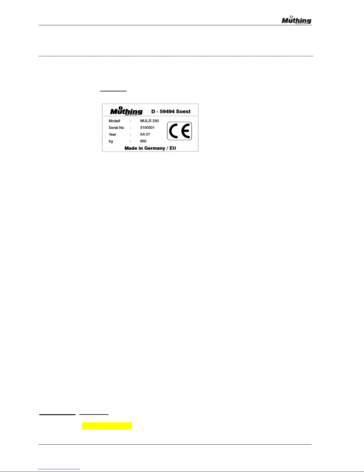
Please copy the data from your Müthing mulcher and the gearbox, which you will find on the type
identification plates. The gearbox identification plate is mounted directly on the gearbox and the
machine identification plate is mounted outside on the left at the rear of the mulcher housing and
matches the following specimen
:
Model / Type............. : MU – C/S.................................................
Serial number........... : ................................................................
Year of manufacture : ................................................................
Gearbox identification :...............................................................
Attachment type ...... : .........fixed .............shiftable
The following information may be useful later:
Machine purchased from :...............................................................
First used on............ : ................................................................
Oil and (For recommendation see maintenance schedule)
grease used ............. : ................................................................
Colour shades used: yellow = RAL 1007 black = RAL 8349
Accessories
(please tick)
Rotor with tungsten carbide hammer flails
(The serial number is
also embossed on the
machine under the
V-belt drive guard!)
Page 9

Instruction manual – MU-C/S 9
CE – Compliance declaration
Compliance declaration
Pursuant to guideline CEE 89/392/EWG and subsequent amendments
We
Müthing GmbH & Co KG Soest
Am Silberg 23
D – 59494 Soest
declare on our sole responsibility, that the machines listed below
MU-C/S Flail Mowers
(Model, type and serial number as stated on the identification plate)
to which this declaration refers, conform to the relevant safety and
health requirements of EC–guideline CEE 89/392 and subsequent
amendments, guidelines CEE 91/368, 93/44 and 93/68 and
machine guideline 98/37 EC.
In order properly to implement the safety and health requirements referred to in the EC
guidelines the following norms were consulted
EN 745 : 1999, EN 1553 : 1999, prEN 13524
D – 59494 Soest, 01.09.2003
The safety officer
Page 10

10 Instruction manual – MU-C/S
Warranty registration
Customer’s copy
Please leave in the operating manual
Date .................................................
I confirm that I have taken delivery of the Müthing mulcher together with the instruction manual
and spares list and that I have been instructed in the operation of the equipment and received
information on safety and risks from your authorised dealer.
I also confirm that I have read and understood the instruction manual and am in agreement with the
instructions included therein. This particularly applies to the chapter on safety, first use and
guarantee.
Mulcher Model / Type MU – C/S............................ Gearbox .......................................
Working width ............................................
Serial number ............................................
Year of manufacture ............................................
Supply date ............................................
Supplied by ...............................................................................................................
...............................................................................................................
............................................... .............................................................................................
Signature Stamp and signature of authorised dealer
Provided you return the following sheet promptly within 10 days of delivery to Müthing,
GmbH & Co. KG, Soest we will guarantee the machine in accordance with the guarantee
terms listed under Point 9.
Page 11

Instruction manual – MU-C/S 11
Warranty Registration (Please return to Müthing)
Name ........................................................................ First name.................................................
Postcode......... ....................................Town / City Street .................................................
Telephone.................................................
Messrs
Müthing GmbH & Co KG
Am Silberg 23 Fax .................................................
D – 59494 Soest
e-mail .................................................
Date .................................................
I confirm that I have taken delivery of the Müthing mulcher together with the instruction manual
and spares list and that I have been instructed in the operation of the equipment and received
information on safety and risks from your authorised dealer.
I also confirm that I have read and understood the instruction manual and am in agreement with the
instructions included therein. This particularly applies to the chapter on safety, first use and
guarantee.
Mulcher Model / Type MU – C/S............................... Gearbox ......................................
Working width ..............................................
Serial number ..............................................
Year of manufacture ..............................................
Supply date ..............................................
Supplied by ...............................................................................................................
...............................................................................................................
........................................ ...............................................................................................................
Signature Stamp and signature of authorised dealer
Please separate here and post to Müthing in Soest.
Page 12

12 Instruction manual – MU-C/S
To enable the guarantee to become effective from the supply date this sheet must be
returned within 10 days of the supply date to Müthing GmbH & Co. KG, Soest.
(Please remove this sheet and post it to Müthing, Soest. Thank you ! )
Page 13

Instruction manual – MU-C/S 13
Notes on using and retaining the instruction manual
This instruction manual and spares list should be regarded as part of the delivery and kept
safe. If the machine is sold on the present user should pass it onto the new owner.
The instruction manual should be kept so that it is always at hand and can also be used
during operation.
Read the manual carefully and follow the instructions before using the machine for
the first time. Each chapter is a complete document in itself and can generally be
referred to later for information on specific operations.
The information contained within the instruction manual should also be passed on to
anybody who is going to use the mulcher or who will be concerned with it in any way.
It is advisable to check that all these people have read the instructions in full or that
they have heard and understood them.
Apart from general advice and instructions particular attention should also be paid to all
safety instructions and danger warnings relating to use of the machine.
Enter the data for your machine (model, gearbox, working width, basic equipment and any
special equipment, serial number and year of manufacture into the appropriate fields and
return the original purchase and guarantee declarations to us before using the machine.
When working on or with a P.T.O. shaft it is essential to read the separate P.T.O. shaft
instruction manual beforehand.
Before fitting any additional units to a tractor or traction vehicle, you should also take
account of any information provided in the instruction manual for these vehicles on
the fitting and use of attachments.
The instruction manual includes essential information for using the machine correctly and
safely. The practical experience that you acquire as a user is equally important.
As far as information contained in this Instruction Manual and Spare Parts List is concerned
we reserve the right to make any improvements and changes to our product range that we
find necessary without notice. We are not however obliged to transfer these improvements
and changes to machines already sold or to their instruction manuals.
Please remember - especially after a fairly long period of use or when asking
questions or ordering spare parts - always to provide the equipment data that has
been entered so that we can identify the technical details for your equipment
precisely and avoid supplying incorrect information or parts.
For further information please contact us direct. We shall be pleased to help! You can find
our telephone numbers on the first page of this manual.
The term “tractor” will be used throughout for tractors, traction vehicles or other vehicles!
Page 14

14 Instruction manual – MU-C/S
5. Technical data, information on fittings and accessories
You will find a precise description
and the technical data for your specific machine on pages 6
and 7 of the attached spare parts list.
Note:
Find out the precise performance data and maximum permissible
tractor/vehicle KW (HP) for your machine along with the minimum tractor
weights (see next page).
Never exceed the permissible power rating – your mulcher might be damaged
as a result!
Basic equipment
for MU-C/S series mulchers:
Three-point linkage
Three-point linkage for rear mounting Category I with permanenly mounted side mulcher support
arm
Mounting offset facility
Fixed side mounting – no sideshift – no automatic breakaway system
mulcher can be shifted vertically (for operating ranges see table on the following page)
Gearbox with integrated freewheel for 540 rpm
Rotor with M scoop flails
Removable shredding bar
P.T.O. shaft
Special equipment - accessory
available for this series (at additional cost):
Rotor with tungsten carbide hammer flails
You can find further information and the precise scope of your Müthing mulcher in the attached
spare parts list on page 8 or ask your Müthing mulcher dealer.
Page 15
Instruction manual – MU-C/S 15
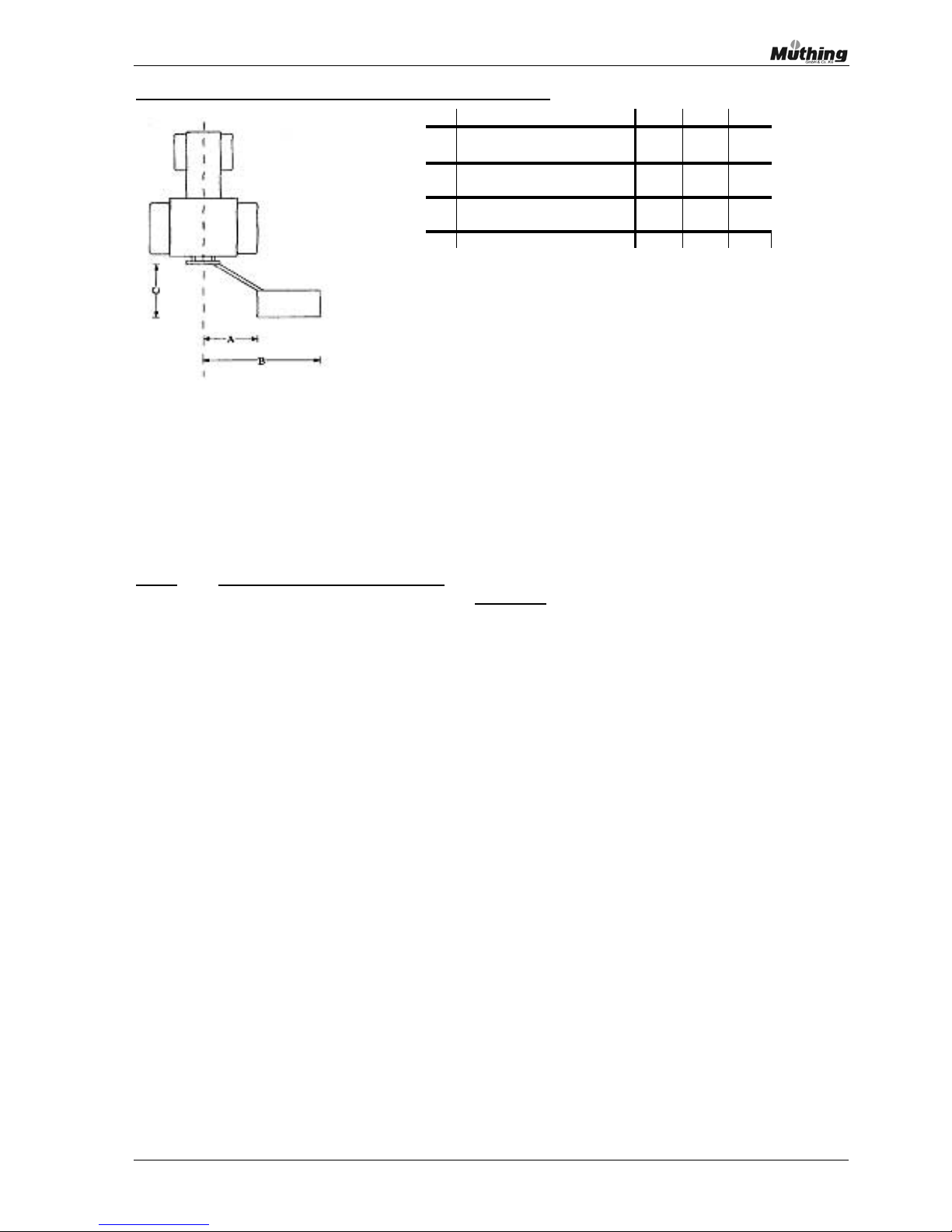
Operating ranges and minimum tractor weight MU-C/S
* The minimum tractor weight largely depends on the track width and the weight distribution of the
vehicle. It may be necessary to use ballasting.
Note:
For designs with left-hand layout (United Kingdom etc.) information regarding
operating ranges should normally be reversed.
(Right instead of left and left instead of
right!)
Working width in c
m
80 100 120
Side mounting
in cm to rig ht or le ft
Transport length
in cm to r e ar
External measurement
in cm to rig ht or le ft
Minimum tractor weight in kg
900 * 900 * 900 *
B
140 160 180
125
A
60
125
C
60 60
125
Page 16

16 Instruction manual – MU-C/S
6. Safety
The following words and symbols are often used in the Instruction Manual for particularly important
information:
• Note:
Special information, instructions and regulations for avoiding injuries to
people, damage to property and avoiding accidents.
If you see this symbol please be aware that there is a possibility of personal injury or
damage to property.
Please read the following information closely and pass it on to anyone else using the
equipment.
• Note: Special details concerning the efficient and economical use of the machine and
features requiring particular attention .
Note: Always adhere to the Safety and Accident Prevention
Regulations listed below !
Appropriate use
Your Müthing mulcher uses up-to-date technology and has been built to comply with all the latest
safety regulations. Despite this, the mulcher can still present a danger to life and limb of the user
and third parties, and damage can be caused to property, the tractor and the mulcher itself if it is
used for unsuitable purposes or otherwise misused.
The mulcher can only function safely, efficiently and without any technical problems if the Instruction
Manual is closely adhered to.
Note:
Any faults that can affect the safety and operation of the mulcher must be
rectified promptly by a trained mechanic.
The mulcher has been design specifically for grass and similar light undergrowth, such as the
trimming of plant stems to within a finger width from the ground.
The mulcher is only suitable for mulching flat areas and for ditches, slopes, path edges and dikes
etc. in farming, landscape gardening or communal areas. Generally speaking a Mulcher can only be
used at the absolute minimum distance when the whole mulcher casing is parallel with the ground.
There are no other acceptable uses for a mulcher. If it is used for any other application the user is
solely responsible for any damage that may result.
Appropriate use also includes adhering closely to the manufacturer's guidelines on operation,
maintenance and repair, complying with regulations relating to inspection and servicing schedules
and maintenance and adhering to safety instructions and notes on risks plus accident
prevention regulations.
The mulcher may only be serviced or repaired by someone who has an in-depth knowledge of its
technical characteristics and is familiar with necessary safety precautions.
It is advisable to practise the separate working stages several times, so that you are familiar with the
effect that the mulcher has on the tractor, before carefully beginning the first jobs.
Page 17

Instruction manual – MU-C/S 17
Note:
All accident prevention, health and safety, traffic and other generally
recognised regulations relating to safety and occupational medicine must be
complied with at all times to constitute appropriate use.
Your mulcher is a piece of equipment that requires proper handling. The mulcher must never be
used by children, teenagers or other people who are not familiar with the Instruction Manual
.
Note:
Carrying passengers on the mulcher whether you are working or not is
prohibited. It is also prohibited for people to stand on or climb on to the
machine or position themselves underneath the machine without adequate
support and safeguards even when it is stationary
!
People are prohibited from loitering in the mulcher danger area when the
machine is being started or used. The safe distance for people to stand behind
the mulcher is 80 m and must be adhered to.
Don’t use the mulcher at night or in poor visibility.
Leave the machine in the condition it was built for – to be used as a mulcher. You must not make
any additions, alterations or modifications to the mulcher without consulting us and obtaining our
written permission beforehand. This also applies to installing or changing the settings of safety
devices.
Note: Existing safety devices must not be altered or removed. Do not make any
changes or modifications!
Changes and alterations will invalidate the warranty and may give rise to legal action if the user
injures a third party or causes damage to property.
Note:
Please note the maximum tractor power allowed for the mulcher. The use of a
more powerful tractor can damage the mulcher and such damage is not
covered by the warranty.
Before using the tractor/vehicle and mulcher familiarise yourself with their
characteristics and be sure to read the manuals for the tractor, the mulcher
and the P.T.O. drive as well as this Instruction Manual.
Note:
Only fit original Müthing replacement parts.
These ensure a perfectly fitting, quality component and preserve your
warranty.
Improper use
The mulcher may only be used as described above. Any other use than that described above is
improper and consequently impermissible. It will invalidate all warranties, guarantees and
product liability entitlements!
Improper use includes:
• using the mulcher to break up or loosen the ground or carrying out any other work on the soil or its
surface
Page 18

18 Instruction manual – MU-C/S
• cutting up wood thicker than 1 cm or other wood-cutting procedures
• using the mulcher on stony ground, for cutting up stones, or for cutting up waste or rubbish on
areas about to be mulched without removing debris beforehand
• using it in the elevated position without any direct contact with the ground
• using the mulcher at night or in poor visibility
• working without keeping the necessary safe distances from people and objects
• carrying passengers on the mulcher whether you are working or not
• people standing on or climbing onto the machine
• working under the machine without adequate support and safeguards
• allowing the mulcher to be used by children, teenagers or other persons who are not familiar with
the Instruction Manual
• removing or changing safety facilities, or making any other alterations or modifications to the
equipment
• Exceeding the maximum permissible tractor/vehicle performance (KW-HP) and/or falling below the
minimum permissible tractor/vehicle weight.
Traffic regulations
As soon as the fitted mulcher ventures onto the public roads it must comply with the relevant
national highway code, and traffic and transport regulations. (including lighting and warning sign if
prescribed).
Even tractors with a fitted mulcher, which do not enter a public road, are still subject to regulations
regarding weights and axle loads.
Note: If the mulcher is mounted on the rear, the front axle might be underloaded and
require an additional front weight to be fitted.
Attach weights at the front if necessary !
Please adhere to maximum speeds, maximum weights and permissible axle
loads and never exceed them.
Please bear in mind that the mulcher and counterweights will have a major influence on the
handling, stability, steering and braking performance of the tractor, and adjust your driving
behaviour accordingly. Be careful when turning corners and taking bends.
Side mulchers develop very considerable leverage. So that the left side of the tractor (or with lefthand models the right side of the tractor) can suffer a substantial reduction in load, especially when
taking bends. Drive considerately and always put the machine into the proper transport position
each time you finish work!
Note: When transporting the mulcher always ensure that the tractor’s tail lights are
not obscured, the mulcher is in the middle or vertical transport position and the
transport lock is activated.
Fit all prescribed warning plates and additional lights.
Only drive in the proper transport
position when transporting.
Page 19

Instruction manual – MU-C/S 19
Safety instructions and notes on risks plus accident prevention regulations
For your safety....
This part of the Instruction Manual contains rules of conduct for use of the machine and safety
instructions that you must adhere to for your safety and to avoid possible risks
.
The listing is very extensive and much of the information does not apply to the equipment supplied.
The information summary however refers to safety rules and possible risks
that are often
uninentionally ignored when machines and equipment are used on a daily basis.
• Every time that the machine and the tractor are used, check beforehand that they can both be
used safely for mulching and on the road.
• Adhere to all safety and accident prevention regulations in force!
• Warning and information plates attached to the machine provide important information on
avoiding risks. Pay attention to them and work safely!
• Observe the relevant regulations when using public highways!
• Before starting work familiarise yourself with all the facilities and operating devices along with
their functions. Once you have started work it is already too late!
• Operators should wear tight-fitting clothing. Avoid loose clothing!
• Keep machines clean to avoid risk of fire!
• Check the immediate area before starting and operating the equipment! (Children!) Make
sure that you can see sufficiently clearly! Make sure that there is a minimum safe distance of
80 m behind you!
• Never leave the mulcher running without someone in attendance.
• Carrying passengers on the mulcher whether you are working or not is prohibited.
• Link up the machine as laid down in the manual and only attach it to the prescribed devices!
• Special care must be taken when attaching equipment to or removing it from the tractor.
• Put the machine into an appropriate position before fitting and removing supports! (Stability)
• Always fix weights to the correct attachment points as described in the manual!
• Please adhere to permissible axle loads, overall weight and transport measurements
!
• Check and mount transport equipment – such as lighting, warning notices and any protective
devices!
• The central or vertical transporting position should always be used for all mulcher mounting
positions, regardless of whether they are front-, side- or rear-mounted. This minimises the
Page 20

20 Instruction manual – MU-C/S
danger of tipping over or of the lights being obscured. Always use the transport lock and apply
safety catches.
• Tripping devices for quick-release couplings must hang loose and not trip of their own accord in
the bottom position!
• Never leave the driver’s platform while driving!
• Attachments, trailers and ballast will have an influence on the tractor’s handling, steering and
brakes. So make sure that your steering and brakes can cope!
• When working or transporting the machine always ensure that the mulcher’s centre of gravity is
so positioned that the stability of the machine is not impaired.
• Bear in mind the wide load and the balance weight when taking bends.
• Don’t operate the machine until all safety devices are in place and fully functional! Check that all
fastenings are secured by split pins or eyebolts!
• Ensure that the plate guards at the front of the machine are functioning and can move freely and
that the rear rubber guard is undamaged.
• In the case of machines with movable protective guards attached at the side always make sure
that they function properly – and clean them if they get soiled!
• Everybody apart from the operator must keep well clear of the machine!
• Keep well outside the machine’s turning and swivelling range!
• Do not operate hydraulic folding wings if there is anybody within swivelling range!
• All hydraulic or other power-operated equipment has points that are subject to crushing or
shearing
• Always ensure that machines with a manual tilting mechanism are completely stable!
• Machines with power-driven tools risk being lifted by trailing balance weight. Do not approach
until they are at an absolute standstill!
• Exercise great caution when working on uneven land.
• Before leaving the tractor, place the mulcher on the ground, turn the tractor engine off, remove
the key and ensure that the handbrake is on.
• Nobody should stand between the tractor and the mulcher without first making certain that the
tractor cannot roll away by applying the handbrake or ensuring that the tractor wheel is wedged.
• Secure swung-in frames and excavation devices in the transport position.
Page 21

Instruction manual – MU-C/S 21
Mounted equipment
• Before fitting or removing the mulcher ensure that the three point linkage is secured to prevent
unintentional lifting or lowering of the linkage.
• When connecting to a three-point mount all three points must match or be adjusted until they
match.
• Check carefully after fitting the mulcher that the tractor’s lower linkage is properly
secured.
• Points subject to crushing and shearing in the area of the three-point linkage are capable of
causing injury.
• Do not position yourself between the tractor and the machine when actuating the external
control for the three-point linkage!
• When the machine is in the transporting position always ensure that the tractor three-point
linkage has sufficient side-locking!
• When travelling on the road with the machine raised ensure that the operating lever is locked to
prevent it being lowered unintentionally!
• If there is a blockage never try to remove mulch or debris before the mulcher has been shut
down and disengaged, the tractor turned off, the key removed and all turning parts have come to
a complete standstill.
Hydraulic system
• The hydraulic system is under high pressure!
• When connecting hydraulic cylinders and engines ensure that the hydraulic pipes have the
proper connections!
• When connecting the hydraulic pipes to the tractor hydraulics, ensure that there is no pressure
at either the tractor- or the machine-end.
• If there are hydraulic connections between the tractor and the machine, coupling sleeves and
plugs should be labelled to rule out faulty operation! You risk causing an accident if connections
and functions are reversed (e.g. raising instead of lowering)!
• Check hydraulic pipe connections regularly and change them if they become damaged or worn!
The replacement hoses must match the machine manufacturer's specifications!
• Use suitable aids when looking for leakages so as to avoid injury!
• Fluids, such as hydraulic oil, ejected at high pressure can penetrate the skin and cause serious
injury! If you are injured seek medical help immediately
! (Risk of infection!)
• Before working on the hydraulics, disengage any equipment, depressurise the system and turn
off the engine!
• Don’t hang out safety chains until they have been released. (Cylinder must be full of oil).
Page 22

22 Instruction manual – MU-C/S
Maintenance
• The mulcher should be inspected regularly for outward signs of damage and defects. This
applies especially to cutting flails and their mountings, and drive belts which should be
checked for signs of breaks, cracks, or excessive wear and tear.
• Replace immediately all cutting flails and mountings that show any signs of damage or are
cracked or heavily worn! If a cutting tool or mounting breaks during use, parts could fly out
and cause injury. When replacing parts use original Müthing spares!
• When maintaining, servicing and cleaning the machine, or correcting faults it his essential to
have the drive switched off and the engine stationary! - Remove the ignition key and ensure
the handbrake is on!
• Check nuts and bolts regularly to ensure that they fit properly and retighten them as
necessary!
• If you are carrying out maintenance work on a mulcher in the raised position always make
sure that you use suitable supports and that the rotor is stationary!
Never work under
unsupported loads !
• When changing implements with cutting edges always use suitable tools and gloves!
• Oil, grease and filters should be properly disposed of!
• Always isolate the current before working on the electrical system!
• Disconnect generator and battery cables before doing electrical welding work on the tractor
and mulcher!
• Spare parts must at least meet the specifications laid down by the equipment manufacturer!
This will always be the case if you use original spares!
Page 23

Instruction manual – MU-C/S 23
P.T.O. drive
• Only use P.T.O. shafts that we have approved.
• Shaft guards and funnel guards for the P.T.O. shaft must be fitted at both the tractor and
mulcher ends and be in good condition!
• Ensure that P.T.O. shafts have the proper pipe covers in transport and operating positions!
• Do not fit or remove the P.T.O. without first turning off the engine and removing the keys!!.
• Always make sure that the P.T.O. shaft has been correctly mounted and secured!
• Secure the P.T.O. shaft by locking the chain to prevent it rotating.
• Before engaging the P.T.O. always make sure that the selected output drive speed matches the
gearbox speed set on the mulcher.
• Make sure that there is nobody in the danger area before you switch on the P.T.O. drive!
• Never engage the P.T.O. drive with the engine switched off!
• When working on the P.T.O. shaft never let anybody stand anywhere near the rotating P.T.O. or
the P.T.O. shaft!
• Note: Danger from flying parts and debris!
Before engaging the mulcher P.T.O. shaft,
make sure that you clear everybody from the 80 m danger area
and check that the
plate guards or chain guards at the front and the rubber protection bar at the rear
are fitted and intact.
• Always disengage the P.T.O. shaft if there is too much distortion and it is not required!
• Take care when disengaging the P.T.O. shaft. It is dangerous if the rotor is still turning.
• Don’t get too close to the machine at this point. Don’t start work on it until it is completely still.
• Don’t clean, grease or adjust the P.T.O.driven device or the coupling shafts until the P.T.O. has
been disengaged, the engine turned off and the ignition keys removed!
• Fit the disengaged couplings to the mounting provided.
• Repair all damage to the P.T.O. shaft before starting work on the machine.
Page 24
24 Instruction manual – MU-C/S
Warning and information signs
Please note all warning signs for operating the mulcher without risk.
Information signs help you to service and maintain the machine by pointing out grease points, and
oil level and drive belt tension indicators.
Replace warning and indicator symbols if they go missing or become illegible. You can obtain
missing symbols through our spare parts service.
Please remove all dirt, oil, dust and grease, and ensure that the surface is clean and dry, before
sticking replacement signs onto the mulcher.
When fitting new components as part of a repair please fit the necessary signs to the replacement
part.
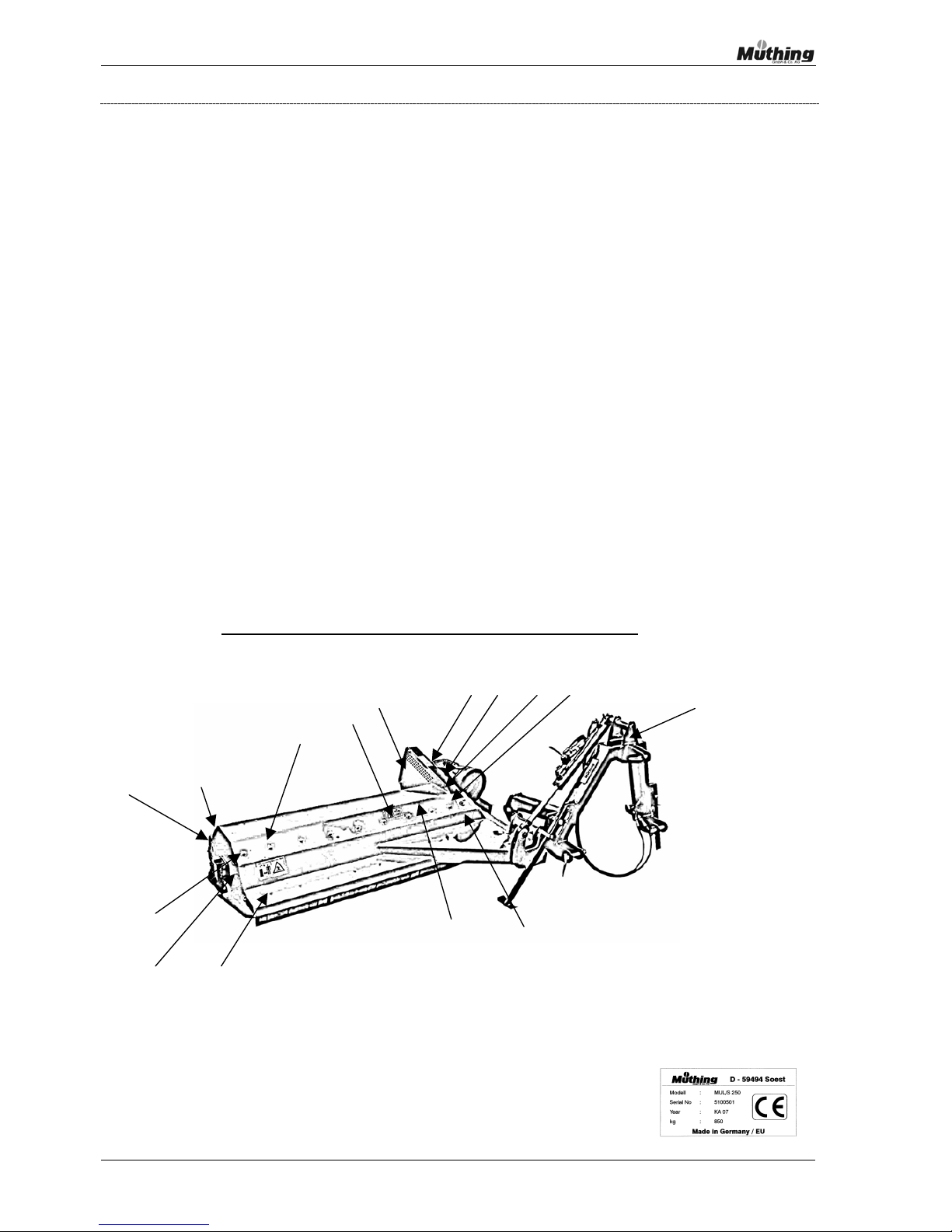
Warning and information signs on the mulcher
You will find warning or information signs on certain points on the mulcher to indicate danger,
maintenance work required, or information on using the mulcher.
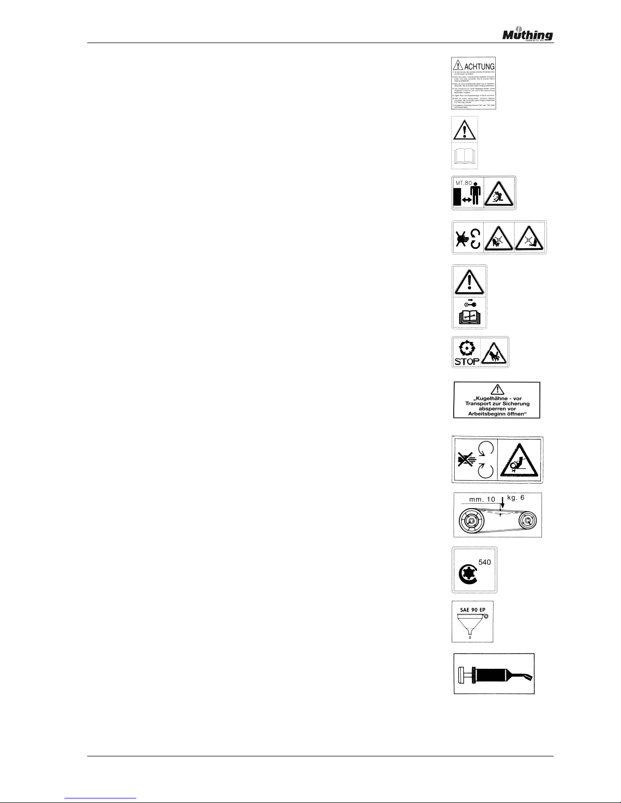
You will find the warning and information signs together with their positions and brief explanatory
notes on the following pages.
Positions of warning and information signs on the mulcher.
9 12 10 3
13 8
6
5
4
13
2
7 11
13 1
1
Serial plate
Page 25
Instruction manual – MU-C/S 25
2
Important information.
Read and take note.
3
Read the Instruction Manual
4
Keep a distance of 80 m.
Danger area!
5
Rotating parts
Risk of injury to hands and feet
Do not touch !
6
Before operation read the Instruction Manual.
Park the tractor and remove key.
7
Stop - Do not touch !
Aggressive tools - risk of injury
8
Close the ball valve for transport.
9
Rotating parts/drive belt. Do not touch!
Danger !
10
Ensure all drive belt tensions are set!
Correct tension 10 mm travel at 6 kg pressure.
11
Gearbox speed 540 rpm.
12
Use SAE 90 EP oil
13
Grease point
Page 26

26 Instruction manual – MU-C/S
7. Using the mulcher for the first time
Your Müthing mulcher will have been delivered to you by our authorised dealer fully assembled
and ready for use and you will have also been instructed on how to use it and given details of
possible risks and safety measures that need to be taken.
Below you will find the information essential for the handover, the checks to be carried out, the
necessary settings and on working with the mulcher.
Taking delivery of the mulcher
Please check that all of the following components have been supplied.
The delivery includes:
→ the mulcher in its standard version.
→ support rollers or wheels
→ three-point headstock
→ P.T.O. shaft (if ordered)
→ Instruction Manual with Replacement Parts List
→ all other special equipment and accessories ordered
Please report any damage that may have occurred during transit or any missing components to the
haulage company straight away Ensure that the driver confirms any damage. If in doubt please
contact our authorised dealer or us direct.
Note: Please check that all screws, nuts, bolts are firmly seated and tight, and that
the drive-belt is correctly tensioned. Retension as necessary. Please repeat
this check no later than 30 minutes after using the machine for the first time.
Check the gearbox oil level and that of the extension shaft , if fitted. Check all
grease points, topping up the oil and re-greasing as necessary.
Note: It is essential to check that the drive on the mulcher and the drive on the tractor
are precisely set to 540 rpm. (See plate mounted on gearbox). If the two do not
match please arrange for our authorised dealer to change it for you.
Failure to match drive speeds could cause serious damage to the mulcher’s
rotor and gearbox.
Page 27

Instruction manual – MU-C/S 27
Attaching equipment to a tractor or other vehicle
Select a suitable tractor of sufficient weight for the mulcher and ensure that the maximum power
allowed is not exceeded. The use of a more powerful tractor can damage the mulcher and such
damage is not covered by the warranty. A tractor that is too light can become unstable or tip
over!
Please attach the mulcher as described, fix it to the proper mounting points on the lower links and
the upper link and then secure it with the locking pin.
The MU-C/S Series is normally fitted with a Category I
mounting.
Note: When using quick-coupling devices for attaching to the lower links always use ball
joints without guides!
Guides or other mounting aids can cause damage to the P.T.O.
Note: When connecting to a three-point mount all three points must match or be adjusted
until they match.
Then, after attaching the lower linkages of the tractor, centre and secure them with the aids
provided on the tractor.
Then gently raise the lower links so that the headstock is precisely vertical and straight. Readjust
with the upper link if necessary.
If the mulcher is inclined too far forward it will cut too low and may clog and dig in. Having the
mulcher inclined backwards will place too much strain on the support roller. In both cases there is a
risk of debris such as stones etc flying out to the front or the rear when you are working,
endangering other people as well as yourself. If the lower link and the upper link are set correctly as
described, the glide shoes on the mulcher housing will be parallel with the ground.
Then put the support leg into the correct working position, lock it and secure it with a locking pin
and anchor.
Note: Please note the safety instructions, details of risks and accident prevention
regulations on pages 16 -26!
Page 28

28 Instruction manual – MU-C/S
Installing the P.T.O. drive
A P.T.O. shaft is normally included with the sale of a Müthing mulcher. If you already own a P.T.O.
shaft and wish to use it, or you wish to use a P.T.O. supplied at a later date, please note that you
may only use P.T.O. shafts of the sizes and dimensions that we have recommended. If you have
any questions on whether your existing P.T.O. is suitable please contact us.
The P.T.O. shaft must frequently be adapted to the tractor when first connected. If the P.T.O. is too
long it could cause damage to the P.T.O. or to the mulcher. Always
have this work carried out by a
specialised workshop
.
Then slide the P.T.O. shaft onto the mulcher’s journal bearings and the P.T.O. stump on the tractor
and secure it as described by the P.T.O. drive manufacturer.
Do not fit and remove the P.T.O. unless the motor has been turned off and the keys removed.
Always read the P.T.O. manufacturer’s Instruction Manual to ensure that the P.T.O. is fitted properly
and safely. It is essential for the P.T.O. to be fitted with a joint guard and an integrated securing
chain to prevent the guard from turning with the shaft.
Funnel guards at both the tractor and mulcher ends along with a shaft guard must be fitted to
comply with safety regulations.
Before engaging the P.T.O. always make sure that the selected output drive speed matches the
gearbox speed set on the mulcher.
As a rule the P.T.O. should remain on the machine after work. So remove the shaft from the P.T.O.
stump on the tractor and store the disengaged P.T.O. shaft on the mount or chain provided on the
headstock.
Müthing MU-C/S series mulchers are equipped with a freewheel in the gearbox as standard so they
do not require any freewheel P.T.O. shaft.
Note: Please note the safety instructions, details of risks and accident prevention
regulations on pages 16 -26!
Page 29

Instruction manual – MU-C/S 29
Transporting the mulcher
Before transporting the Mulcher ensure that the Mulcher has been correctly fitted and that the
transport lock attached to the lower linkage has been fixed and that the Mulcher is in the vertical
position, centrally located so that the centre of gravity of the tractor is not impaired and the Mulcher
is not protruding from the sides.
Please take special care that the position that you have selected for the mulcher does not obscure
the tractor lights.
Always transport MU-C/S rear mulchers tilted vertically upwards (90° ). With the MU-C/S series
look out for any projection to the side. - Do not exceed the maximum permissible transport
width!
Please bear in mind that as soon as the mulcher enters a public road it must comply with the
relevant national road regulations.
This also means adhering to the maximum transport width and distances to be maintained in front of
or behind the tractor.
Where necessary fit a warning plate or additional lights.
Always ensure that the mulcher has been secured (refer to the tractor's Instruction Manual) with the
proper transport safety locks.
Rear/side mulchers should be secured for transportation by using the ball valve on the hydraulic
cylinder for the 45/-90 ° position as follows:
Before transportation
shut off for safety (rotate lever 90° towards pipe)
Open before commencing work (position lever parallel to pipe
).
Check whether the front axle is underloaded when mounting. If the mulcher is mounted on the front,
the rear axle might be under-loaded and require an additional rear weight to be fitted. Even tractors
with a fitted mulcher, which do not enter a public road, are still subject to regulations regarding
weights and axle loads.
Please bear in mind that the mulcher and counterweights will have a major influence on the
handling, stability, steering and braking performance of the tractor, and adjust your driving
behaviour accordingly. Be careful when taking corners and bends and reversing. The machine may
swing out!
Side mulchers develop very considerable leverage, so that the left side of the tractor (or, with lefthand models, the right side of the tractor) can encounter a substantial reduction in load, especially
when taking bends. Drive carefully and always put the machine into the proper transport position
every time after work.
Once transportation is complete, release the transport lock, then slowly and carefully lower the
mulcher to the ground and put it in the working position or park it .
Note: Please note the safety instructions, details of risks and accident prevention
regulations on pages 16 -26!
Page 30

30 Instruction manual – MU-C/S
Switching the mulcher on and off
Before engaging the P.T.O. or the mulcher please check that the mulcher is securely mounted, that
all the safety devices are fitted and that you are certain that nobody is in the danger area (80 m
behind mulcher).
Please remember to keep at a sufficient distance from all rotating parts and to maintain this safe
distance until you are sure that all of the components have come to a complete standstill.
The rotor and the cutting flails between them constitute a considerable gyrating mass. This mass
has a high power requirement when the machine is switched on and switching it off releases
substantial residual forces.
To cope with this all Müthing mulchers are fitted with drive belts to absorb and to compensate for
these forces.
Nevertheless starting the mulcher at maximum load may be sufficient to damage and even destroy
the tractor`s P.T.O., the P.T.O. shaft, the gearbox or the drive belts on the mulcher.
The same applies to turning the mulcher or P.T.O. off too quickly, when the gearbox, the P.T.O.
shaft, the built-in free wheel.or the the tractor´s P.T.O. can be damaged.
To avoid operating errors or causing possible damage please observe the following instructions and
recommendations.
Always place the mulcher in the lowered position and have the tractor running at a low engine
speed before engaging the drive. Then you can increase engine revs to their full operating speed
and start work.
Before stopping work or at the end of a row first reduce the tractor's engine speed and wait for the
mulcher's rotational speed to drop before .disengaging the mulcher drive.
Note: Most modern tractors are fitted with automatic engagement on the P.T.O. so
that the P.T.O. engages or disengages automatically when the mulcher is
lowered or raised.
If your tractor is fitted with such an automatic feature please ensure that the
facility for reducing the tractor’s engine speed before the engine is switched on
or off and then speeding it up automatically is engaged; otherwise you must
reduce it yourself manually.
Note:
Please note the safety instructions, details of risks and accident prevention
regulations on pages 16 -26!
Page 31

Instruction manual – MU-C/S 31
Switching off the machine
Before putting the mulcher away at the end of work, be sure to give the mulcher a good wash down
in a suitable place and then spray it with a suitable preservative or preserving oil.
Always grease the bearings and the other grease points as recommended in the lubrication
schedule and check that grease extrudes from the appropriate grease points. This cleans the
bearings and prevents dirt and moisture from entering. Also check the oil levels in the gearboxes
and extensions.
Please ensure that all rotary parts are at a complete standstill when you do this work!
Finally park the mulcher on level ground at the intended spot. Extend the support leg to the correct
length so the Mulcher is stable and secure the locking bolts with the clinch pin provided.
Carefully lower the Mulcher to the ground, turn the tractor off, remove the key and put on the
handbrake.
Then withdraw the P.T.O. shaft from the tractor P.T.O as described in the manufacturer’s instruction
manual and place the P.T.O. in the holder provided or the holder on the three-point linkage.
If there are hydraulic connections release the hydraulic pressure and decouple the connections on
the hydraulic pipes from the tractor. Seal the connectors with the protective caps and place the ends
in the holders provided.
Remove the lower and top linkages from the three-point linkage on the tractor.
At the end of the season or before long periods without use we recommend that the machine
should be thoroughly cleaned and sprayed with a commercially available preservative. Check that
all parts and fastenings are firmly seated, replace any damaged parts and grease the machine
carefully. Carry out an oil-change if necessary and park the machine safely in a dry place. Where
possible also cover the machine with a plastic tarpaulin, open underneath, to protect it from dust.
By doing this you will ensure that the mulcher is ready for work whenever you require it.
Note:
Please note the safety instructions, details of risks and accident prevention
regulations on pages 16 -26!
Page 32

32 Instruction manual – MU-C/S
Settings
Before you start mulching adjust your mulcher to the relevant operating conditions and check that
the machine’s gearbox speed matches the tractor’s P.T.O. speed.
The height of the mulcher is set via the back-up roller (basic setting by means of the three holes)
and the upper link (fine adjustment). On the roller you should generally use the central hole on the
side plate.
The best cutting height is 4 -6 cm, which matches up with the middle hole on the side plate for
securing the support roller/wheels. If you are cutting dense material or driving at higher speeds the
cut can be raised by using the lower hole; to achieve an extremely close cut the back-up roller or the
wheels can be moved to the upper hole with the machine being driven at low speed.
Don't cut too short!
Don’t cut the grass too short – give it a chance to sprout up again!
In unfamiliar areas such as fallow ground and field edges it is a good idea to use the lower hole, i.e.
cut higher. There is no way of telling what debris and root stalks are lurking there.
The cutting height must be always greater than 2.5cm (ideally 4-6 cm) and the Mulcher must not
come into contact with the ground or you will risk damaging it!
To adjust the cut raise the machine 3 – 4 cm above the ground, turn off the engine and the
machine, align the machine and once all rotating parts are at a complete standstill release the side
mounting screws for the support roller in the side plates. Then place the support roller in the desired
position and refasten the screws in this position. Retighten nuts and bolts well.
Note: Before you start work raise the mulcher slightly and support it to minimise any
risk of injury! Never work under unsupported loads!
The mulcher must be parallel with the ground when working
.
If the mulcher is inclined too far forward it will cut too low and may clog and dig in. Having the
mulcher inclined backwards will place too much strain on the support roller. In both cases there is a
risk of debris such as stones etc flying out to the front or the rear when you are working,
endangering other people as well as yourself.
The top linkage must also be set so that the P.T.O. shaft moves parallel to the ground, the mulcher
is supported by the support rollers or wheels, and the machine sits level. The bottom edge of the
side or skid plates must be parallel with the ground.
Then centre the lower links
so that the machine cannot move to and fro in the three-point linkage.
Then set the tractor P.T.O speed to that of the mulcher as indicated on the gearbox (540
rpm).
If possible, steering device for 45 – 90° cylinder at floating position!
The machine should adjust to
the ground of its own accord. This takes pressure away from pivots and cylinders.
Should it be necessary to change the machine’s gearbox speed, please have it done by a
specialised workshop!
Page 33

Instruction manual – MU-C/S 33
Note: Please note the safety instructions, details of risks and accident prevention
regulations on pages 16 -26!
Working with the machine
Never start work with the mulcher unless all protective devices are fitted and fully functional on both
the mulcher and the P.T.O. Check that all movable fastenings are secured by split pins or eyebolts.
Make sure that all front plate guards or chain guards and the rear rubber guard are complete and
fully functional.
Before starting work slowly lower the mulcher from the transport position, carefully place it on the
ground and move it into the working position.
Then check that the machine has the correct settings. (Roller/wheels secured in the middle setting,
three-point linkage completely vertical, machine aligned parallel to the ground, P.T.O speed setting
matching that on mulcher’s gearbox, rear hydraulic device floating freely, swivel cylinder 45 – 90° in
floating position).
Always ensure that the job you intend to carry out with the mulcher is an appropriate one,
and that you comply with all the safety and accident prevention regulations on pages 16 -26
during and after work.
Always engage the drive to the mulcher at low engine speeds, wait for the rotor to turn and slowly
increase speed to operating level. Now you can start the tractor and begin mulching!
Maintain engine speed to enable the machine to work properly and provide a good cut.
For mulching ditches and embankments all mulchers can be raised to an angle between 45° and
90° degrees to the horizontal. This can be achieved by using the appropriate hydraulic control to
bring the machine to the desired position.
Please ensure that the tractor’s handling is not affected during this operation and that the mulcher
works flat against the ground and not up in the air.
When driving ensure that the hydraulic setting allows the three-point linkage to float freely (raise
lower links slightly so that the headstock is absolutely vertical and straight) with the control device
for the 45–90° cylinder floating as the best possible alignment for the machine is achieved by having
the mulcher resting on the support rollers combined with the hydraulic levelling device.
Before disengaging the P.T.O., first reduce the motor speed to prevent damage to either the
mulcher or the P.T.O. itself.
Note: Only work in straight lines. When turning or taking bends always disengage the
mulcher in good time at a low engine speed and raise it slightly . This protects
the support roller and bearings and prevents damage to the mulcher and roots.
Note: The mulcher may only be used in open land where there is sufficient distance
between the mulcher and people, animals, houses, roads etc.
The danger area behind the mulcher is at least 80 m.
The machine should only be used for flailing and mulching light organic material and harvest
residues.
Page 34

34 Instruction manual – MU-C/S
Be cautious of any debris in the work area that could become entangled in the mulcher such as
glass, metal, wood, stones and other objects.
These objects could cause personal injury or damage the machine if they are driven over, crushed
or shattered.
Take special care of objects such as large stones, kerbstones, tree stumps, plastic sacks and debris
which could lie on the ground and cause an obstruction.
These objects could block the rotor, damage the mulcher or create a dangerous situation.
The MU-C/S series with fixed side mounting has no breakaway system
. You must take great care
when you drive or operate this machine and be aware of obstacles.
Please take special care when working on slopes or on uneven ground
as this will increase the risk!
Always work slowly and carefully with the Mulcher, and work on the uphill side of the tractor so that
the risk of the tractor tipping over is reduced.
On steep hills never work across the slope but always up and down. Don’t work on extreme slopes
– you risk having a serious accident.
The mulcher’s safety devices will not function at extreme angles or on very uneven land – the
chances of injury or damage are increased, so that use of the mulcher is prohibited in such
circumstances.
Please note that using the mulcher at its lowest setting increases energy requirements and also
increases wear on the cutting flails and drive belt as well as on the mulcher as a whole. Please use
the settings recommended below:
Note: The cutting height must alw ays be greater than 2.5cm (ideally 4 -6 cm) and the
mulcher must not come into contact with the ground or you will risk damaging
it, which will constitute improper use and invalidate your guarantee.
To keep the machine in good order, please adhere to all lubrication schedules and inspect the drive
belts and oil levels regularly (see Maintenance - Lubrication Schedule).
Using the mulcher can cause very high temperatures because of the intense power transmission
and the high demands placed on machine, gearbox and extension shaft
.
This rise in temperature is normal and should not induce any sense of alarm, provided that the
tractor performance matches the type of machine and you never exceed the maximum permissible
tractor power.
If there are any faults or problems associated with the mower please refer to Chapter 10 of this
Instruction Manual.
At the end of a working session, return the mulcher to the transport position and ensure that the
transport locks are actuated or fitted before returning or putting the mulcher back into storage.
Note: Please note the safety instructions, details of risks and accident prevention
regulations on pages 16 -26!
Page 35

Instruction manual – MU-C/S 35
Mounting additional equipment and modifications
These notes will explain to you which options may be fitted later and which conversions are
permissible and possible.
Note:
Work such as changing rotors or installing wearing skids must only be carried
out by trained technical staff – in case of doubt please have the work listed above
carried out in a specialised workshop ! An incorrect modification could cause
extensive damage, which would invalidate any warranty claims.
Note: Please note the safety instructions, details of risks and accident prevention
regulations on pages 16 - 26!
Hydraulics
In the case of MU-C/S series mulchers the 45 – 90° vertical swing is carried out hydraulically.
For this the tractor requires 1 double-acting hydraulic connection, which must have a floating
position to facilitate working.
When connecting the hydraulic pipes, remove from the holders provided, remove the protective
caps and fit correctly to the tractor's hydraulic couplings.
Make sure that the connection has properly engaged. Incorrectly fitted couplings can cause oil leaks
and pollute the environment.
When removing from the tractor, refit the protective caps and re-secure the hydraulic pipes in the
holders provided.
Always ensure that the pressure has been released from the tractor’s or the mulcher’s hydraulic
system as appropriate before attaching or removing hydraulic connections or cylinders from the
tractor or mulcher.
Make sure that you always use good-quality hydraulic pipes and approved matching connections,
which comply with the relevant industrial standards. These pipes and connections must also bear
the approved markings. You can either obtain these hydraulic pipes from us or from specialised
companies, which will also be pleased to answer any further questions.
Check all hydraulic pipes regularly (at least once a year) by examining the surface for damage such
as cuts, chafing, kinks and squashing, and investigate the condition of the material for cracks,
leakages etc. Damaged pipes must be changed immediately
. A hydraulic pipe should never be kept
in use for longer than 5 years.
Note:
Please note the safety instructions, details of risks and accident prevention
regulations on pages 16 -26!
Page 36

36 Instruction manual – MU-C/S
8. Valuable aids for mulching work
Mulching is a method of cutting vegetation, which combines several processes in one, by reducing
the amount of vegetation remaining on the ground, while saving energy, labour and expense.
Rapid rotting and composting ensures that the nutrients contained in the biomass can be utilised
and metabolised directly on the surface, leading to a further accumulation of humus. This will
encourage biological processes in the soil on a sustained basis and have a positive impact on the
water balance.
If you intend to remove the nutrients and biomass from the surface for any reason (adequate soil
quality, avoiding too rapid regrowth, or for reasons associated with conservation) it is easy to
compact the mulched material for transportation, storage and composting.
To achieve the best possible composting process it is essential to have a good quality of mulch,
which involves fragmenting the material and stripping out the fibre.
If mulching must be completed quickly it is also possible to increase driving speed, reduce power
and save energy at the same time, as long as the required quality of cut and operating conditions
permit.
This is not always easy, but it is generally possible to get close to optimum operating performance
by bearing in mind the points below.
Guidelines for taking care of both your mulcher and your soil
A mulcher is a removable tractor utility tool, which is supported by roller or wheels mounted at the
rear which bear the main weight of the machine..
It is therefore important to adjust the height of the mulcher so that it sits parallel to the ground
without tilting forward or backward. The effectiveness of the work will suffer if it is incorrectly
positioned in either direction; if the side plates operate incorrectly or cut into the soil this could
damage roots and jam the mulcher, and debris such as stones could be thrown forward or to the
rear.
The support roller or the wheels control the mulcher’s cutting height and should normally be set in a
central position to give a cut of 4 -6 cm. The minimum gap between the ground and the cutting flails
is 2.5 cm (= 1 inch).
Anything greater than this protects the ground, roots and the mulcher, and generally requires the
least power. So don't cut too short! Give the grass a chance to sprout up again
When working on uneven ground or in very heavy vegetation it is advisable to lower the
roller/wheels to the lowest hole and then increase the cutting height.
In this position and cutting height you can drive at about 5 - 10 kph (4 - 6 mph) depending on ground
conditions.
In unfamiliar areas such as fallow ground, the edges of fields and road verges it is a good idea to
use the lower hole, i.e. cut higher and drive very slowly. There is no way of telling what debris and
rootstalks are lurking there.
When taking bends
a great deal of the mulcher’s weight shifts onto the support roller on the inside of
Page 37

Instruction manual – MU-C/S 37
the bend and on the bearings. As these bearings have no differential this subjects them to a very
heavy load.
If the mulcher is taken round sharp bends on the back-up roller even the best bearings in the world
cannot stand this indefinitely. So don’t drive the mulcher on the support roller when taking bends!
Raise it on bends and when turning.
There is a similar risk when taking bends to that which results from the machine being incorrectly
mounted or set too low (support roller/wheels in the uppermost hole) in that the mulcher’s side
plates can cut into the ground and damage the soil, roots and the mulcher itself.
This can be remedied by skids mounted on the sides, now available as a regular item from
Müthing Mulchers. When using skid plates it is important to note that they should not bear the
weight of the mulcher as this would cause skid marks and damage the roots. The weight should still
be carried by the support rollers/wheels.
As far as speed is concerned: the slower the better! The longer the chaff remains in the housing the
more it is cut and crushed, which means that it will rot better and more quickly.
Driving slowly at the edges of fields, roads and tracks also makes it easier to stop in time to avoid
obstacles.
When using the offset hydraulic cylinder always perform this operation slowly and carefully and
avoid damaging the mulcher, plant roots or the ground, and protect the tractor against strong and
unintended surges or movements.
To achieve a uniformly good cut, keep as close as possible to the stated P.T.O. speed – never
exceed it! If the rotor can operate at the rated speed, suction is intense and crushing is good. If the
engine speed is too high the rotor, bearings and the power train could be damaged
Müthing mulchers are capable of cutting and mulching long grasses and large quantities of
vegetation reliably. And so as a rule very few cuts are required, just one per season may provide
adequate care with maybe one follow-up. In bad weather mulching can generally be postponed to
no great disadvantage and so avoid slipping and wasting power.
The basic principles are as follows: The shorter the better and the quicker it will rot. The length of
cutcan be influenced by the driving speed and number of shredding bars (depending on type). The
more shredding bars you use, the shorter the cut. But with more shredding bars you use more
power and lower the capacity. The slower you drive, the longer the mulch spends in the housing and
the more it is chopped.
We therefore suggest: Generally speaking, only use one shredding bar. Müthing mulchers are so
constructed that a single shredding bar will produce an adequate quality of mulch. Only use a
second shredding bar (can be fitted later on larger machines) for special circumstances when you
need to cut very small (e.g. for sensitive grazers such as horses and want rotting to occur as quickly
as possible).
With mulching you can almost always wait until it is dry and the ground is in reasonable condition.
It doesn’t have to be done on one particular day.
This saves time, energy and expense compared with alternative cultivation methods.
Page 38

38 Instruction manual – MU-C/S
Fitting the correct cutting flail.
Various cutting flails can be used depending on the vegetation (grass, harvest remains, twigs and
woody materials, bushes with various foreign objects, but in most cases the original Müthing “M”
scoop flail has proved itself more than adequate for all the above operations.
Müthing “M” scoop flail
The Müthing “M” scoop flail with its wide, self-sharpening straight cutting edge is the
middleweight at 350 g and has no trouble cutting material up to 1 cm thick.
This tool’s reinforced lug in an extremely strong flail makes it virtually fracture-proof; the shackle and
the special tool mountings together mean that this tool is very good at avoiding objects to the rear
and at the same time, its weight-induced centrifugal force lends it a high degree of stability and
enables it to produce a high-quality cut.
We recommend that you use this design of flail when it is essential for the cut always to be parallel
with the ground, such as when grass has to be cut short.
It is also important to note that ground with a high foreign object content, as found on stony ground
or when working along road edges, can limit the effectiveness of the “M” scoop flail. In these
circumstances it has proved beneficial to use one of the following variations.
Müthing “M” tungsten carbide hammer flail
The highly-tempered “M” tungsten carbide flail with its wide, polished and self-sharpening straight
cutting edge is the middleweight at 350 g (without flail), which can easily cut material up to 1.0 cm
thick .
Its double leg linkage in an extremely strong flail makes it virtually fracture-proof; the shackle and
the special tool mountings together mean that this tool is very good at avoiding objects to the rear
and the side and, at the same time, its weight-induced centrifugal force lends it a high degree of
stability and enables it to produce a high-quality cut.
This “M” flail is suitable for all jobs requiring an even, clean cut, good fragmentation, material
reduction and a high throughput.
Nevertheless, under difficult working conditions, this quality of work may have higher energy
requirements and/or require you to adjust to slower driving and working speeds, so that the machine
can function well and economically.
Page 39

Instruction manual – MU-C/S 39
Use of shredding bars
The degree to which the vegetation is to be mulched depends on the number and shape of the
shredding bars fitted.
The particular form of housing with the built-in shredding bar, the opposing edges in the housing,
the distance between the tools and the shredding bar also have a crucial influence on the shredding
and the quality of the mulch. These factors are precisely geared to the cutting diameter and the
rotational speed of the mulch rotor and tools.
With the shredding bars and flails working hard, the mulch will be of good quality, the mulch will rot
quickly and produce good-quality compost.
On the other hand, with more shredding bars fitted, a larger volume of vegetation is cut and cutting
tough and hard materials will have a negative impact on energy requirements, driving speed and
general wear and tear when material is reduced to this finer grade.
That is why the shredding bar installed as standard in your Müthing mulcher is removable. This
gives you the opportunity to change the degree of fragmentation depending on the quality of the
mulch required.
The basic principles are as follows: The more shredding bars you use, the shorter the cut. But with
more shredding bars you use more power and lower the capacity.
We therefore suggest: Generally speaking, only use one shredding bar
. Müthing mulchers are
constructed so that a single shredding bar will produce a good quality of mulch.
Page 40

40 Instruction manual – MU-C/S
9. Cleaning and maintenance
Regular cleaning, servicing and maintenance can extend the life of your Müthing mulcher
considerably and improve the reliability and quality of the cut.
The responsibility for carrying out thorough and regular servicing lies in your hands.
→ Take care to clean the Mulcher in a suitable place
and spray it with a preservative
when you finish work.
→ Ensure that all main components are serviced regularly.
→ Inspect the mulcher regularly for wear and faults.
→ Replace worn parts and carry out necessary repairs
Please note that damage caused by failing to comply with the maintenance and servicing procedure
will not be covered by the warranty!
The following information on checking for wear and tear, servicing and maintenance should be
considered as general information.
Owing to the wide range of situations in which this machine operates, especially very intensive use
or difficult working conditions, we ask you to draw up a specific maintenance and inspection
schedule after the first session of work, to inspect and service the machine and take account of the
experience that you have gained.
For the inspection and servicing of the tractor and the P.T.O. drive shaft, which should be undertaken at the same time, we ask that you refer to the manufacturer's servicing manual for each item of
equipment.
Servicing does not as a rule require any particular expertise or specialised workshop. It should
nevertheless only be conducted by proficient and suitable people at suitable and appropriate
locations. Ensure that no pollution (soil, water, air) occurs!
Maintenance work, solving difficult problems, replacing drive belts or cutting flails or complex
modification work such as drive speed conversions should always be carried out by qualified
mechanics in a specialist workshop.
Make use of any reduction in your workload over the winter months to give the mulcher a thorough
check and a full service. Your mulcher will thank you for many years to come.
Note:
Please note the safety instructions, details of risks and accident prevention
regulations on pages 16 -26!
Page 41

Instruction manual – MU-C/S 41
General checks and maintenance
Check your machine on delivery and at regular intervals thereafter.
The most important checks are listed systematically below:
→ Mulcher supplied complete and undamaged ?
If not, please contact us immediately.
→
Any missing warning signs must be reported !
If not, please reorder any that are missing.
→
Check all nuts and bolts are properly seated and secure!
If not, please re-tighten.
→
Are all drive belts tight ?
If not, please re-tension.
→
All grease points sufficiently greased - grease visible ?
especially on the rotor bearings and idle roller bearings.
If not, re-grease where required (please refer to greasing plan) page 7)
→
Is there sufficient oil in the gearbox?
If not – please top up or drain (see: Checking oil levels and changing oil).
→
Check that the drive speed of the gearbox is the same as the tractor’s P.T.O speed!
If not – have it converted in a specialised workshop!
→
Check that all safety devices are fitted to the mulcher and are fully functional!
If not, please contact us immediately or have them refitted or cleaned.
→
Check approved P.T.O. shaft’s protective guards are fitted and functional!
If not, please contact us immediately or change P.T.O.
→
Check if all necessary hydraulic connections are present, fitted and functional!
If not, please contact us immediately or arrange for them to brought up to specification
in a specialised workshop.
→
Machine properly mounted or capable of being so ?
If not, please contact specialised workshop.
If any components are missing or fail to function correctly please contact your authorised dealer or
the Müthing company direct.
Please do not start using the mulcher until it has passed all the checks and been fully
serviced as listed above.
After mounting the mulcher start with a test run
, taking account of all necessary safety
precautions (see pages 16 - 26), make sure that the tractor’s HP does not exceed the
permissible maximum and check all functions and noise levels. All components should run
smoothly without any clattering, with minimum vibration, and produce a single tone with no other
disturbing noises.
Page 42

42 Instruction manual – MU-C/S
Note: If any abnormal sounds or movements are heard during the test run, such as
vibration, clattering etc., turn off
the mulcher immediately, contact a
specialised workshop and inform us direct.
Note: Please remember to re-tension the drive belts no later than thirty minutes after
they have been used for the first time (drive belts usually stretch the first time
they are used) and after the machine has been running for one hour ensure that
all nuts and bolts are secure (retighten as necessary).
Tasks forming part of general maintenance work and which should be carried out regularly
include:
→ Checking and greasing bearings, support rollers, rotor and all other moving
components at the grease points indicated . (See Lubrication Schedule)
→ Checking for damage from foreign bodies or other obstructions as well as removing
cable or strips of plastic which have wrapped themselves around the rotor or support
wheels/roller.
→ Removing all debris and repairing any damage.
→ Checking oil levels and changing the oil in the gearbox
→ Checking the drive belt tension and re-tensioning as required.
→ Checking and tightening up all nuts and bolts on the machine.
→ Checking, working in and cleaning or replacing all protective devices such as P.T.O.
guard, front plate guard, rear rubber guard, locking bolt and split pins, protective flaps
etc.
→ Checking that the cutting flails are not worn and are firmly seated and replacing worn
or broken flails.
→ Cleaning the cutting flail holders and checking for sufficient movement.
Always carry out this servicing carefully. The greasing points are all marked with adhesive signs,
and their positions are shown in the section entitled “Warning and Information signs” (Chapter 6).
You can find further information and descriptions of the individual points and procedures on page 7
and the following pages.
Note: If there are recurring problems, unfamiliar noises, sudden surges in energy
requirements, vibration, smoke, overheating of drives or gearboxes or any
unaccountable changes in the mulcher’s behaviour, stop work immediately,
check the mulcher for faults and rectify them.
If there is any vibration it is essential to check that flails are in good condition
and complete, and that they can move freely.
If necessary, stop work and service the mulcher – remember that an
unbalanced rotor can destroy the bearings and cause other damage.
Note: Please note the safety instructions, details of risks and accident prevention
regulations on pages 16 -26!
Page 43

Instruction manual – MU-C/S 43
The most important work is listed once more in the following table.
When What Notes
At least every 4
hours of operation
Grease the rotor- and back-up roller
bearings on both sides
via the grease nipple with normal lithium
lubricating grease
The grease must be seen to
emerge when you lubricate the
back-up roller bearings – Give the
rotor bearings 4 to 5 squirts on
each side
Daily Grease rotor or landwheels
If wheels are in use instead of the
support roller
Daily
Grease or lubricate sideshift mechanism
and grease points on support arm
If machine can be side-shifted
Daily Service and lubricate P.T.O. shaft
Adhere to P.T.O. shaft
manufacturer’s operating and
maintenance instructions
After 30 to 40
operating hours
Carry out first gearbox oil change
Only use SAE 90 EP
or SAE 140 transmission oil
Every 200
operating hours, at
least once a year
Carry out oil change in gearbox
Only use SAE 90 EP
or SAE 140 transmission oil
Regularly
Check gearbox oil level and top up if
necessary
Only use SAE 90 EP
or SAE 140 oil
Regularly Check drive belt tension Retighten as necessary
Regularly Retighten nuts and bolts
Replace unusable and worn nuts
and bolts
Regularly
Check protection devices and ensure
that they function
Replace defective appliances
Regularly Tool and equipment check
Replace defective tools with nuts
and bolts, repair device
Note:
Reattach and secure all protection devices after carrying out maintenance or repairs.
Page 44

44 Instruction manual – MU-C/S
Changing cutting flails
If the cutting flails are to be changed (“M” type scoop flail or “M” type tungsten carbide flail) the
mulcher must be placed on the ground, detached from the tractor, raised using suitable lifting
devices and properly supported and secured.
If suitable equipment is not available, please have the work carried out by a fully equipped
specialised workshop.
Note:
Never work under unsupported loads !
To replace the cutting flails
please proceed as follows:
→ After ensuring that the mulcher is properly supported and secured at a suitable
location, turn the rotor slowly by hand to each flail in turn in order to reach a suitable
position and ensure that all cutting flails can be easily accessed.
→ Before unscrewing the nut please clean the nut and any protruding thread with a wire
brush. Apply a little oil, penetrating oil or grease to make it easier to turn.
→ Remove the self-locking nuts on the lugs with the correct fitting spanner (24 mm). and
with one hand holding the cutting tool to prevent it falling, pull out the securing bolt
from the other side of the tool mounting.
→ Exchange the worn or damaged cutting tool for an original Müthing cutting tool of
the same type (“M” type scoop flail or “M” type tungsten carbide hammer flail).
→ Insert a new bolt correctly into the mounting so that the screwhead fits properly, and
cannot turn any further, pull the bolt through the cutting tool and mounting on the
other side as far as it will go.
→ Fit a new self-locking nut
to the bolt and secure it tightly.
→ Repeat this process until all worn or damaged cutting flails have been replaced.
→ Check that all the nuts and bolts are sitting correctly and are secure.
→ Lower the mulcher carefully to the ground, following the appropriate safety and
accident prevention procedures.
→ After a short period of use (max 2-3 hours) recheck that all the nuts and bolts are
correctly seated and secure.
Note:
Replace immediately any cutting flails that show any signs of damage, are
cracked or are heavily worn!
Failure to do so can cause parts to be thrown out, unbalance the rotor, damage
the bearings or other problems.
Note: Any imbalance can destroy the mulcher!
So, either repair it immediately or contact a suitable specialised workshop!
Note: When replacing cutting flails always try to replace complete sets or at least
opposing pairs in order to balance out the weight on both sides of the rotor
uniformly at the same time.
(Uneven weight distribution on the rotor or failure to balance out the new flails
will unbalance the rotor)
Page 45

Instruction manual – MU-C/S 45
Always fit new nuts and bolts when changing the cutting flails. Nuts and bolts
are also subject to wear and tear. They can fracture.
Note: Only fit Original Müthing parts, and nuts and bolts. Failure to use original
Müthing spares and attachments will invalidate the warranty.
To prevent being cut by the sharp edges of cutting tools always wear thick gloves and use the
proper tools when replacing the cutting flails.
If your Müthing mulcher is equipped with a scoop flail rotor, you can exchange the “M” scoop flails
for Müthing tungsten carbide flails or vice versa at any time, but you must always change the entire
rotor for a complete set.
Note:
Please note the safety instructions, details of risks and accident prevention
regulations on pages 16 -26!
Tensioning and replacing drive belts
Müthing mulchers generally use drive belts for power transmission as their elasticity alleviates and
smooths out sudden peak loads. Peaks can occur when starting, or encountering debris or large
volumes of dense material.
A drive belt is also a low cost sacrificial item which protects both the machine and tractor from
damage if the mulcher is forced to a halt by an obstruction.
The drive belt must be set to the correct tension so that it can work efficiently without excessive
wear. The drive belt tension is correct when a force of about 6 kg can move the drive belt 10
mm inwards at its central position between the two pulleys. This force is equal to the force that
can be applied by fairly strong arm pressure.
To enable you to check the tension of the drive belt you will find a fairly long narrow aperture and
the symbol 10 on the side in the middle of the drive belt guard.
Please check the drive belt tension daily by feeding the end of a ruler through the opening until it
rests on the drive belt. Continue pressing hard. If you can then push the drive belt about another 10
mm further in with the ruler until the resistance is too great the drive belt tension is correct. If you
can push it any further the drive belts are too slack and must be retightened.
Further signs that the drive belt is too slack are reduced performance, excessive heat, smoke or the
smell of burning rubber coming from the drive belt.
Note:
If smoke comes from the drive belt casing, turn off the mulcher and search for
the cause! There is a risk of it catching fire, which could cause serious damage
to the mulcher.
Müthing MU-C/S mulchers are fitted with a manual drive belt tensioning system. Gearboxes and
drive belt pulleys must be adjusted for this manual drive belt tensioning
.
Page 46

46 Instruction manual – MU-C/S
Retension drive belts
manually as follows with the mulcher switched off and disconnected: (Wait
for the machine and all rotating parts to come to a complete standstill!) )
→ Unscrew the bolts holding the drive belt casing and remove the casing.
→ Undo the gearbox fixing bolts on the mounting to move the gearbox
→ Turn the clamping screw or the tensioning screw evenly with a suitable spanner to
adjust the position of the gearbox, increasing (or, if necessary, reducing) the tension of
the drive belt.
→ The correct drive belt tension is obtained when the drive belt gives 10 mm under
a pressure of 6 kg centrally between the two pulleys (strong arm pressure).
→ Then gently retighten the gearbox fixing bolts on the gearbox mounting
→ Ensure that the drive pulleys
run absolutely parallel to the side plate and are
completely flush with one another
! To check this, hold a spirit level against both
pulleys and ensure that they contact simultaneously at all four points. If not,
realign the pulleys.
(Misalignment of the pulleys can cause excessive wear to the drive belts).
→ Finally, tighten all bolts and refit the drive belt casing, checking that all the attachment
screws are sitting correctly and are secure.
→ After approximately 30 minutes work recheck the drive belt tension. After working for 1
- 2 hours check again that all screws and bolts are secure and, if necessary, retension or retighten.
New drive belts have a tendency to stretch on first use depending on quality. It is therefore essential
to inspect drive belts and drive belt tension shortly after replacing them and starting work to avoid
damaging the belts. Inspections can subsequently be extended to longer intervals.
Note: If drive belts are worn, always change the entire set and re-tighten all drive
belts. This is the only way to achieve optimum power transmission!
To replace the drive belts
please proceed as follows: (Switch off, shut down the engine and wait
for the machine and all rotating parts to come to a complete standstill!) )
→ Unscrew the bolts holding the drive belt casing and remove the casing.
→ Reduce the drive belt tension by undoing the fastening bolts attaching the gearbox to
the mounting.
→ Using a rod or a large screwdriver (Don’t use anything sharp, it could damage the
belts!) turn the pulley at the same time to make it easier to remove the belts.
→ Remove the drive belts.
→ Fit the new drive belts - using a rod or a large screwdriver and while turning the pulley
as indicated above – tension the belts as described in the previous section.
→ The correct drive belt tension is obtained when the drive belt gives 10 mm under
a pressure of 6 kg centrally between the two pulleys (strong arm pressure).
Page 47

Instruction manual – MU-C/S 47
→ Ensure that the drive pulleys
run absolutely parallel to the side plate and are
completely flush with one another
To check this, hold a spirit level against
both pulleys and ensure that they contact simultaneously at all four points. If
not, realign the pulleys.
(Misalignment of the pulleys can cause excessive wear to the drive belts).
→ Finally, tighten all bolts and refit the drive belt casing checking that all the attachment
screws are sitting correctly and are secure.
→ After approximately 30 minutes work recheck the drive belt tension, and after 1-2
hours work check that all screws and bolts are secure and re-tension or retighten as
necessary.
Note: When changing drive belts always change complete sets to ensure maximum
power transmission.
Note:
Please note the safety instructions, details of risks and accident prevention
regulations on pages 16 -26!
Page 48

48 Instruction manual – MU-C/S
Oil level checks and oil changes
The gearbox fitted to your Müthing mulcher runs in an oil bath.
The oil level
in the gearbox is correct when it is half-way up the gearbox.
If the gearbox is underfull it can overheat and/or run dry and cause damage, while too much oil can
also cause damage, in extreme cases destroying the gearbox.
The gearbox has an oil-level check plug, which is mounted half-way up the gearbox housing.
The gearbox also has an oil and ventilation screw and underneath a drain plug.
(You can find the precise positions of the screws for your machine on the gearbox diagram and
the relevant parts description in the replacement parts list.)
Oil level check on gearbox:
→ Lower the mulcher, remove it from the tractor, bring it into a horizontal position and
support it with the support leg.
→ Remove the oil level check plug from the side of the gearbox, placing a container
under the gearbox to catch any leakage). )
→ If the level is too high allow the excess oil to run out.
→ If the level is low, top up the oil level until oil starts to run out (see next page).
→ Replace the oil level check plug and screw it tight.
→ Dispose of any leaked oil properly.
Topping up oil in the gearbox:
→ Lower the mulcher, remove it from the tractor, bring it into a horizontal position and
support it with the support leg.
→ Remove the oil level check plug from the side of the gearbox, placing a container
under the gearbox to catch any leakage). )
→ Remove the filling plug and, using a suitable funnel, top up with SAE 90 EP or SAE
140 gearbox oil, taking care not to overfill.
→ If it has been overfilled, allow the excess oil to run out until it reaches the level of the
check plug.
→ Replace the oil level check plug and the filling plug and fasten them tightly.
→ Dispose of any leaked oil properly.
Gearbox oil change
Page 49

Instruction manual – MU-C/S 49
→ Lower the mulcher, remove it from the tractor, bring it into a horizontal position and
support it with the support leg.
→ Remove the oil level check plug from the side of the gearbox, placing a container
under the gearbox to catch any leakage). )
→ Remove the drain plug at the bottom of the gearbox and allow the oil to drain out until
the gearbox is completely empty.
→ Replace the drain plug and screw tight.
→ Remove the filling plug and, using a suitable funnel, top up with SAE 90 EP or SAE
140 gearbox oil, taking care not to overfill.
→ If it has been overfilled, allow the excess oil to run out until it reaches the level of the
check plug.
→ Replace the oil level check plug and the filling plug and fasten them tightly.
→ Dispose of any leaked oil properly.
Note:
Please note the safety instructions, details of risks and accident prevention
regulations on pages 16 -26!
Overhauling the mulcher
As well as carrying out the maintenance tasks listed above it is also essential to check the front
plate guards or chain guards and the rear rubber guard at the mulcher outlet regularly to make sure
that they are intact, undamaged and fully functional.
The plate guards mounted at the front of the mulcher prevent objects from flying forward in the
direction of the driver.
The design of the housing with the rubber guard mounted at the rear of the mulcher enables the
housing to be safely lowered onto the ground and also prevents objects from being thrown
backward.
These components are absolutely essential for the mulcher to operate safely and if they become
damaged they must be repaired or replaced before the mulcher can be used again.
Remove all dirt or debris from in front of, behind, or between the top plate guard mountings.
Changing the plate guards
→ Lower the mulcher, remove it from the tractor, bring it into a horizontal position and
support it with the support leg.
→ Remove the split pin from the mounting rod securing the plate guards.
→ Standing beside the machine
remove the mounting rod completely from the side of the
mulcher, ensuring that the plates cause no injury when they fall
. )
→ Replace damaged guards with Original Müthing protective guards, push the rod
back into the machine from one side and thread in the guards.
Page 50

50 Instruction manual – MU-C/S
→ Push the mounting rod at the other end through the appropriate hole in the side plate
and secure it with a new split pin
.
Replacing the rear rubber guard
→ Lower the mulcher, remove it from the tractor, bring it into a horizontal position and
support it with the support leg.
→ Remove the screws clamping the holding strip to the rubber guard.
→ Remove both the holding strip and the damaged rubber guard.
→ Position the new multi-layered original rubber guard with the two sets of holes in
the rubber guard in alignment with the holes in the mulcher housing so that the
securing screws can be reinserted.
→ Then realign the holding strip from outside against the rubber guard.
→ Reinsert and tighten the screws.
Extensive overhaul work and other work that has not been included in this maintenance
manual should generally only be carried out by trained mechanics in a specialised
workshop.
Should it be necessary to carry out welding work on the mulcher or the tractor, please remember to
remove the alternator and battery first to prevent possible damage from voltage overload.
Use the correct tools for all work, along with safety shoes, fitting overalls and, if appropriate,
gloves.
Note:
Please note the safety instructions, details of risks and accident prevention
regulations on pages 16 -26!
Disposing of the mulcher at the end of its life
Ater many years of use even a good high quality mulcher will reach the end of its life. If this is the
case please dispose of the mulcher correctly to prevent damage to the environment.
Almost all the materials found on the mulcher are recyclable and can be recovered.
Page 51
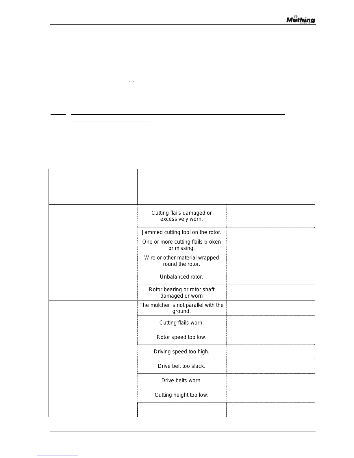
Instruction manual – MU-C/S 51
10 Malfunctions, causes and remedies
The table below contains a list of faults that we have collected in the course of our experience with
mulchers, the possible causes of these faults and the action that you should normally take to
resolve the problem.
If our recommended action fails to cure the fault or further problems arise please contact your
supplier. This will help us to get to the root of the problem and find a suitable solution. We shall use
the experience gained from this information to make further improvements to the mulcher.
Note: Please note the safety instructions, details of risks and accident prevention
regulations on pages 16 -26!
Fault Cause
Solution
Cutting flails damaged or
excessively worn.
Change the worn cutting flails
including mounting nut and bolt in
pairs or as a complete set
.
Jammed cutting tool on the rotor. Clean cutting tool mounting.
One or more cutting flails broken
or missing.
Replace cutting flails.
Wire or other material wrapped
round the rotor.
Remove debris.
Unbalanced rotor.
Check the weighting and
rebalance as necessary.
The mulcher emits excessive
vibration and noise
Rotor bearing or rotor shaft
damaged or worn
Replace the bearing or shaft.
The mulcher is not parallel with the
ground.
Adjust the toplinkage until the
mulcher is sitting correctly.
Cutting flails worn.
Change the worn cutting flails
including mounting nut and bolt.
Rotor speed too low. Increase rotor speed.
Driving speed too high. Drive more slowly
Drive belt too slack.
Check drive belt tension and if
necessary retighten.
Drive belts worn.
Replace complete set of drive
belts.
Cutting height too low.
Lower the support roller/wheels
and /or adjust the toplinkage.
Mulcher operation
and/or
cut unsatisfactory
Cutting height too high.
Raise the support roller/wheels
and /or adjust the toplinkage.
Page 52
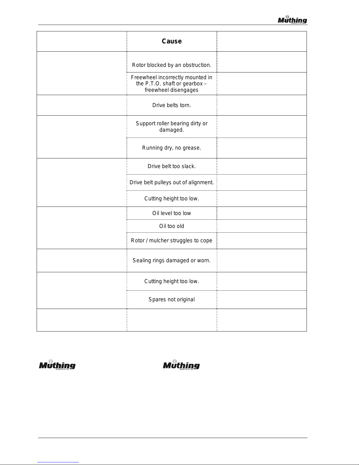
52 Instruction manual – MU-C/S
Fault Cause Solution
Rotor blocked by an obstruction.
Carefully remove obstruction.
Rotor fails to turn
Freewheel incorrectly mounted in
the P.T.O. shaft or gearbox –
freewheel disengages
Change freewheel in the P.T.O.
shaft or gearbox or remount it
Drive shaft turns but not rotor Drive belts torn.
Replace complete set of drive
belts.
Support roller bearing dirty or
damaged.
Replace bearing and grease new
bearing well until grease starts to
exude.
Support roller is stiff or stuck
Running dry, no grease.
Re-grease bearing until grease
starts to exude.
Drive belt too slack.
Check drive belt tension and
retighten as necessary
Drive belt pulleys out of alignment.
Check alignment and adjust as
necessary
Drive belt problems ( too much belt
wear, belts overheat, start to
smoke, reduction in power
transmission)
Cutting height too low.
Lower the support roller/wheels
and /or adjust the toplinkage.
Oil level too low Top up oil
Oil too old Carry out oil change
Gearbox runs hot
Rotor / mulcher struggles to cope
Drive more slowly and/or set back-
up roller lower
Oil loss from gearbox or extension
shaft
Sealing rings damaged or worn. Replace sealing ring.
Cutting height too low.
Lower the support roller/wheels
and /or adjust the toplinkage.
Excessive cutting tool wear.
Spares not original Use original Müthing cutting flails.
Drive elements fractured
Mulcher started too quickly or
damaged by foreign body
Replace the damaged item and
take more care with the mulcher in
future.
If you have any other technical or practical questions about your mulcher please contact us or our
authorised dealer, who will be more than happy to help.
GmbH & Co KG Soest GmbH & Co KG Uffenheim
Tel: +49 (0)2921 – 9651 0 Tel: +49 (0)9842 – 9866 0
Fax: +49 (0)2921 – 73080 Fax +49 (0)9842 – 9866 67
e-mail [email protected] e-mail [email protected]
www.muething.com & www.shop.muething.com
Page 53

Instruction manual – MU-C/S 53
10. Guarantee
Müthing mulchers are manufactured with great care, using modern production methods and are
subject to numerous checks.
Consequently Müthing issues a guarantee as part of its General Terms and Conditions in line
with the following statement (extract from General Terms and Conditions):
1. The rights of the customer with regard to product defects are laid down by law. If the
customer is not a consumer (Article 13 German Civil Code) these rights are restricted by
the provisions of clauses 2 – 8 below.
2. Discrepancies or changes lying within the bounds of relevant technical standards shall not
constitute a defect. The same applies to standard commercial, and technically unavoidable
discrepancies where they do not impair the utility of the goods for use in accordance with
the contract.
3. If a particular quality of the item is agreed a departure from this only constitutes a
negligible defect if the suitability of the item for the contractually agreed use is not impaired
or only to a negligible extent. In this case compensation claims or withdrawal from the
contract as a result of the defect are ruled out.
4. The right of the customer to subsequent performance is restricted to a repair of the item if
this is reasonable for the customer, especially if this can remedy the defect in a similar
fashion to resupplying the item.
5. The customer can only claim that subsequent performance has failed if at least two
attempts at subsequent performance have been unsuccessful and at least 3 weeks have
elapsed since the complaint.
6. The period of grace set by the customer shall be deemed unreasonable if it is less than
three weeks counting from the date on which we were notified of the period of grace.
Periods of grace must be set in writing.
Page 54

54 Instruction manual – MU-C/S
7. We shall only be liable for losses incurred by the customer as a result of defects to the
supplied item in cases of simple negligence up to the level of a typical average loss. This
shall not apply to losses involving loss of life, physical injury or damage to health.
8. With the exception of claims referred to in Article 478 German Civil Code [=BGB] all rights
of the customer arising from the defect shall be statute barred within 1 year of delivery.
This shall not apply to instances of intent and gross negligence, nor to compensation
claims involving loss of life, physical injury or damage to health. Nor shall it apply if an item
supplied or mounted by us is used as a building. In instances of Clauses 2 and 3 the
statutory period of limitation shall apply.
9. Supplying an item other than the due item or a quantity other than the due quantity shall
constitute a defect.
Page 55

Instruction manual – MU-C/S 55
Notes
Page 56

56 Instruction manual – MU-C/S
Notes
© 400010-20080520
 Loading...