

Page 1
Page 3 of 9PplPage 3 of 9
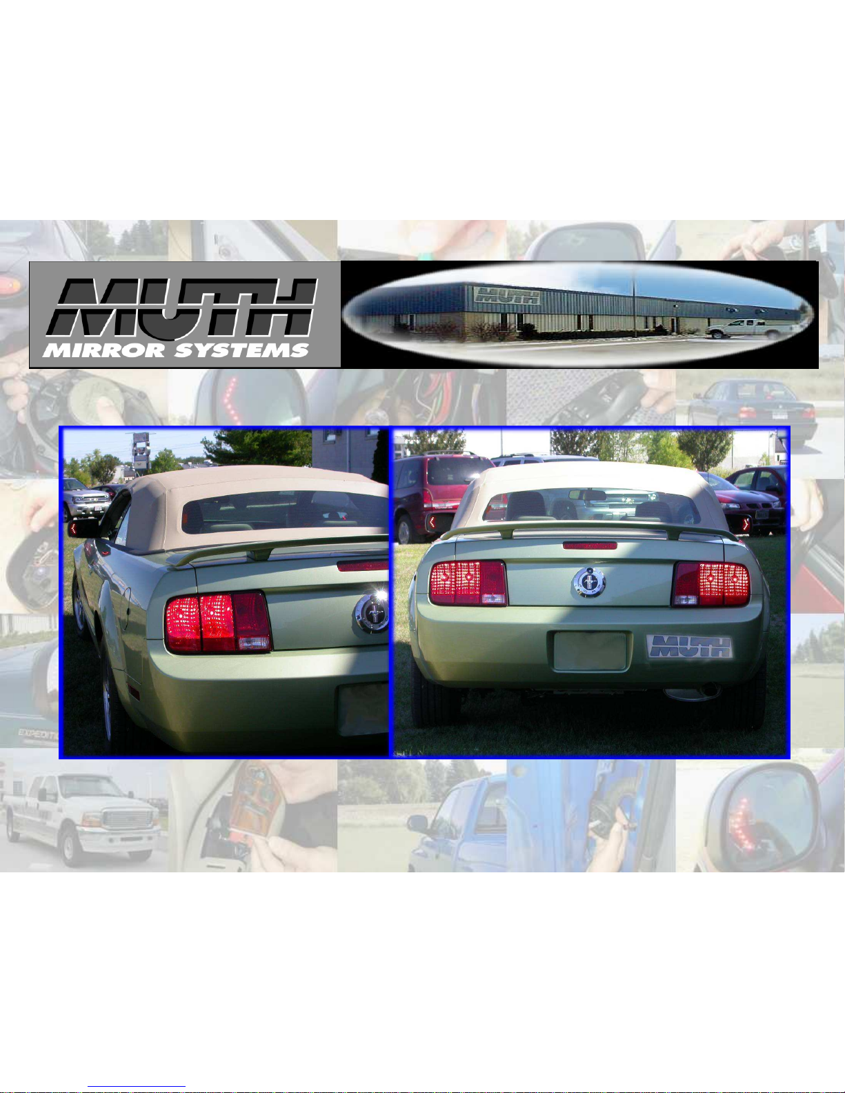
Signal®
Mirror Installation Instructions
2005 – 2009 Ford Mustang
THE safety accessory of the 21st Century.™
P/N 210
-0114-0 Rev. A3 (11/17/08
)
, BTV
© 200
5 Muth Mirror Systems
, LLC
®
Page 2
INCLUDED ITEMS:
1 left and 1 right Signal® mirror
1 left and 1 right wire harness
2 wire taps
2 rubber grommets
2 housing connectors
2 ring connectors
1 instruction manual
REQUIRED TOOLS:
Ratchet with extension or ratcheting screwdriver
10mm socket
Socket wrench
Torx wrench
Large slotted screwdriver
Small pry bar
Gopher wire (rod)
Electrical tape
Wire crimper and stripper
Needle nose pliers
Multimeter or wire tester
Sturdy gloves
Safety glasses or goggles
Utility knife
Drill
1/8” Drill bit
1/4” Drill bit
1/2” Drill bit
PROBLEMS OR QUESTIONS?
Technical Assistance is available by calling
Muth Mirror Systems Technicians at:
1-800-844-6616
Monday through Friday
Between 8:00 a.m. and 5:00 p.m. CST
Or through the Muth web site: www.muthco.com
Or via E-mail: techsupport@muthco.com
Please read instructions prior to installation.
Note: Professional Installation Recommended
Warranty does not cover damage to the vehicle or mirror housing due to improper installation. The following installation
instructions are to be considered as a guide only. Door removal procedures, indicator wire color and location may have changed
since publication of these instructions. The installer is responsible for any damage that may occur during installation.
2
Page 3
Start with
opening
the driver’s s
ide door and lower
ing
the window.
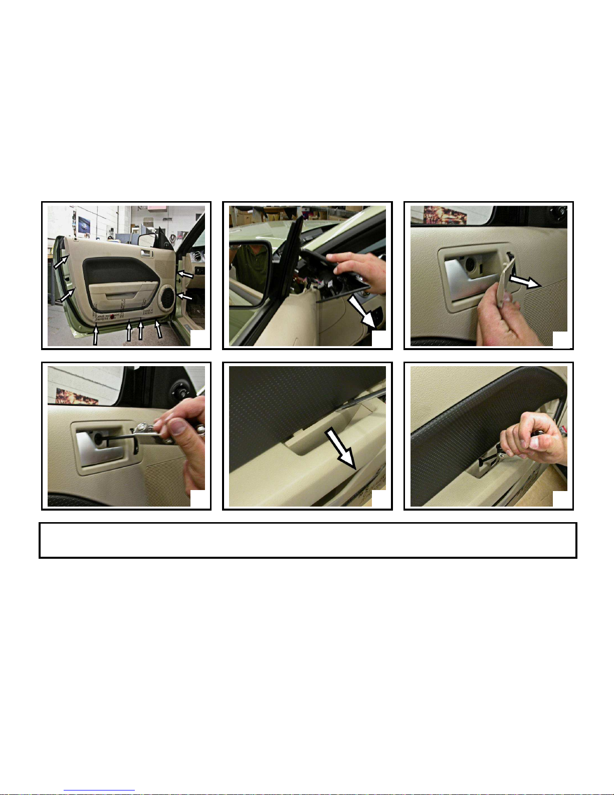
Using a 7mm socket wrench, remove all (8)
hex screws along the perimeter of the door frame
(A)
.
Unsnap corner plastic triangular cover (B). Carefully remove door handle cover using a slotted screwdriver (C). Remove screw in door handle with a T-15 torx wrench
(D). With the slotted screwdriver, remove plastic covering on the grab bar (E). Release the revealed screw using a T-15 torx wrench (F).
B
D E
DOOR PANEL REMOVAL
A
C
F
3
Page 4

K
Carefully pry out the control console with a small pry bar
(G)
. Dis
connect
all
wiring
connections
behind control console and remove it. Using a 7mm socket wrench,
remove screw revealed by the removal of the control console (H). Pull on door panel to unsnap it from door frame (I). Lift up and pull door panel out a few inches
away. Disconnect tweeter and wiring connection (J). Remove door panel and set it aside. Disconnect mirror harness (K1). Secure the mirror housing with one hand,
remove the (3) nuts holding the mirror housing to the door frame using a 11mm socket (K2). WARNING: Not securing mirror housing with one hand before
loosening the nuts could cause the mirror housing to fall and become damaged. Carefully remove mirror housing from door frame and set mirror housing on a
cloth covered surface.
H
J
DOOR PANEL & MIRROR HOUSING REMOVAL CONTINUED
G
I
4
Page 5

MIRROR REPLACEMENT
Push do
wn on the lower
out
board edge
of glass until mirror pivots fully outward. Insert a large
slotted
screwdriver in between the
mirror backing plate and motor actuator
(A)
.
Carefully pry and twist screwdriver until original mirror pops off. If heated, disconnect heater wires from heater terminals and remove mirror. Remove the foam insulation
on the housing sail (B). Using the shorter of the two harnesses from the wiring kit, guide the end with the shrink tube wrapped around it thru the foam insulation, thru the
housing sail (B), and into the mirror housing (C). Use a utility knife, carefully cut the shrink tube and remove it (D). Be very careful not to cut into the wiring harness
itself. Using one of the supplied housing connectors, insert the red wire pin into slot #1 - chamfer side (E). Insert the black wire pin into slot #2 - non-chamfer side (E).
Continue to insert each pin into its hole until the pin snaps into place (not removable). Pull the Signal® mirror wire harness thru housing sail leaving about 4” to 6” of the wire
harness inside mirror housing. Connect the mating connectors on the new Signal® mirror and the Signal® mirror wire harness (F). If heated, reconnect the heater wires to the
heater terminals on the back of the new Signal® mirror (F). NOTE: There is no polarity so the wires may be interchanged. Carefully tuck all wiring behind motor
actuator. Not doing so, could result in wiring interfering with mirror travel. Remove the PSA liner on the PSA disc. Align and center the motor mount onto the motor
actuator. With the palm of your hand, slowly push down on the glass until the new Signal® mirror snaps into position. Press down on all sides to ensure the new Signal®
mirror is fully seated and functional. Replace the foam insulation onto the housing sail.
B
D E
A
C
F
5
WARNING: Safety glasses and sturdy gloves are required for mirror replacement.
Page 6

Guide all wire harnesses thru the hole in the door frame and position the mirror housing assembly on the mirror mount. Reconnect mirror harness (A1). Attach the mirror
housing to the mirror mount with three mirror mounting nuts (A2). WARNING! Do not over tighten the mirror mounting nuts. Find the rubber boot located between the
door frame and vehicle frame. Use a flat screwdriver, push-down from the top and push-up from the bottom to release boot connector from the vehicle frame. Pry out the boot
connector. Uncover the rubber boot from the boot connector. Tape the open end of the Signal® mirror wire harness to the fish rod. Push the fish rod from inside door frame
through the rubber boot (B). Once the fish rod with the Signal® mirror wire harness protrudes through the rubber boot, cut the tape with a utility knife and pull the Signal®
mirror wire harness through rubber boot, removing any slack in the Signal® mirror wire harness. Work the grey boot connector out of the body panel so it faces you. Use 1/4”
inch drill bit, drill an access hole though the upper unused section of the connector. Use extreme caution as not to damage anything around this area, including paint or
wire harness. Insert the Signal® mirror wire harness thru the drilled opening on the boot connector (C). Remove any slack in the Signal® mirror wire harness. Remove
plastic trim pieces on the running board and the kick panel. Use a 1/8” drill bit, drill a pilot hole into the side of the kick panel (D). Re-drill using a 1/2” drill bit (E).
B
D E
WIRE ROUTING
A
C
6
WARNING:
When routing wire into vehicle, it is extremely important to not let wire get pinched or crushed at an
y time.
Avoid window track and sharp edges at all times. Not doing so may cause circuit shortage problems in the long run.
Page 7

Tape the open end of the
Signal® mirr
or wire harness to the fish rod
. Push the fish rod
thru th
e boot connector opening and out
the 1/2” drilled hole (F).
Pull the fish rod thru to get the Signal® mirror wire harness inside the vehicle, and remove any slack in the Signal® mirror wire
harness. Cut the tape with a utility knife and remove the fish rod. Replace the rubber boot back onto the boot connector. Snap
the boot connector back into place on the vehicle frame. Insert the Signal® mirror wire harness thru one of the supplied rubber
grommets. Slide the rubber grommet along the Signal® mirror wire harness and place the rubber grommet into the 1/2” drilled
hole (G). Remove any slack in the Signal® mirror wire harness. Repeat all of the previous steps to replace the factory mirror on
the passenger side door with the new Signal® mirror.
* Before proceeding, please read remainder of instructions for information regarding wiring identification and options.
The vehicle’s electrical wiring is located within the wire bundle on each side of the kick panel. Route the Signal® mirror wire
harness on the driver side to the driver side kick panel. Separate the red and black wires on the Signal® mirror wire harnesses.
Locate a suitable grounding location (grounding bolt, right above the drilled hole, in the kick panel area). Cut the black wire to
length and strip about 3/8” off. Bend about half of the stripped portion of the black wire back onto itself. Insert the black wire
into one of the supplied ring connectors and crimp it into place. Secure the ground ring to the metal framework of the vehicle
using the bolt as shown (H).
G
WIRE ROUTING CONTINUED
F
7
H
Page 8

WIRE IDENTIFICATION
8
TURN & BRAKE
The vehicle’s electrical wiring for the TURN & BRAKE is located within the wire bundle on each side of the kick panel. Locate the WHITE w/ RED STRIPE wire
within the wire bundle on the driver side kick panel. Turn the ignition key so that electrical power is on and activate the driver side turn indicator. Probe the wire
with the wire tester to verify that flashing turn directional power is present. Label that wire as ‘driver side indicator’. Find the RED w/ WHITE STRIPE wire
within the wire bundle on the passenger side kick panel. Turn the ignition key to on. Activate the passenger side turn indicator. Probe the wire with the wire tester
to verify that flashing turn directional power is present. Label that wire as ‘passenger side indicator’.
TURN ONLY
The wiring location for the TURN ONLY is located in a wire loom behind the passenger side headlight. Extra wire will be needed to go from inside the vehicle,
through passenger side firewall opening/grommet and then to the wire loom. Locate the GREY w/ BLACK STRIPE wire within the wire loom. Turn the ignition
key so that electrical power is on and activate the driver side turn indicator. Probe the wire with the wire tester to verify that flashing turn directional power is
present. Label that wire as ‘driver side indicator’. Find the DARK BLUE w/ PINKISH RED STRIPE wire within the wire loom. Turn the ignition key to on.
Activate the passenger side turn indicator. Probe the wire with the wire tester to verify that flashing turn directional power is present. Label that wire as ‘passenger
side indicator’.
Page 9

9
1
USE THE
INCLUDED WIRE TAPS AND FOLLOW THE FOUR STEPS ABOV
E TO SPLICE INTO THE TURN INDICATOR
WIRES
A. Make sure the harnesses are routed securely and enough slack is left for splicing.
B. Splice the RED wire from the driver side harness into the wire previously labeled ‘driver side indicator’.
C. Splice the RED wire from the passenger side harness into the wire previously labeled ‘passenger side indicator’.
D. Activate each turn indicator to verify that the Signal® mirrors are working properly.
E. Reconnect all original wiring. Turn the ignition power to on, check to verify all features are working properly.
F. Replace the plastic door frame moldings, trim, door panels, and all accessories.
3
Muth products are protected by these, and other pending, United States Patents
Muth products are protected by these, and other pending, United States PatentsMuth products are protected by these, and other pending, United States Patents
Muth products are protected by these, and other pending, United States Patents
3,075,779 5,005,009 5,014,167 5,128,659 5,207,492 5,355,284 5,361
3,075,779 5,005,009 5,014,167 5,128,659 5,207,492 5,355,284 5,3613,075,779 5,005,009 5,014,167 5,128,659 5,207,492 5,355,284 5,361
3,075,779 5,005,009 5,014,167 5,128,659 5,207,492 5,355,284 5,361,190 5,481,409 5,528,422 5,619,374 5,619,375
,190 5,481,409 5,528,422 5,619,374 5,619,375,190 5,481,409 5,528,422 5,619,374 5,619,375
,190 5,481,409 5,528,422 5,619,374 5,619,375
5,788,357 6,005,724 6,045,243 6,076,948 6,257,746 6,700,123 6,749,325 6,918,685 7,008,091 7,015,642 7,104,676 D363,920
5,788,357 6,005,724 6,045,243 6,076,948 6,257,746 6,700,123 6,749,325 6,918,685 7,008,091 7,015,642 7,104,676 D363,9205,788,357 6,005,724 6,045,243 6,076,948 6,257,746 6,700,123 6,749,325 6,918,685 7,008,091 7,015,642 7,104,676 D363,920
5,788,357 6,005,724 6,045,243 6,076,948 6,257,746 6,700,123 6,749,325 6,918,685 7,008,091 7,015,642 7,104,676 D363,920
D394,833 D409,540
D394,833 D409,540 D394,833 D409,540
D394,833 D409,540 D425,466 D426,506 D426,507 D427,128 D428,372 D428,373 D428,842 D429,202 D430,088
D425,466 D426,506 D426,507 D427,128 D428,372 D428,373 D428,842 D429,202 D430,088D425,466 D426,506 D426,507 D427,128 D428,372 D428,373 D428,842 D429,202 D430,088
D425,466 D426,506 D426,507 D427,128 D428,372 D428,373 D428,842 D429,202 D430,088
2
4
 Loading...